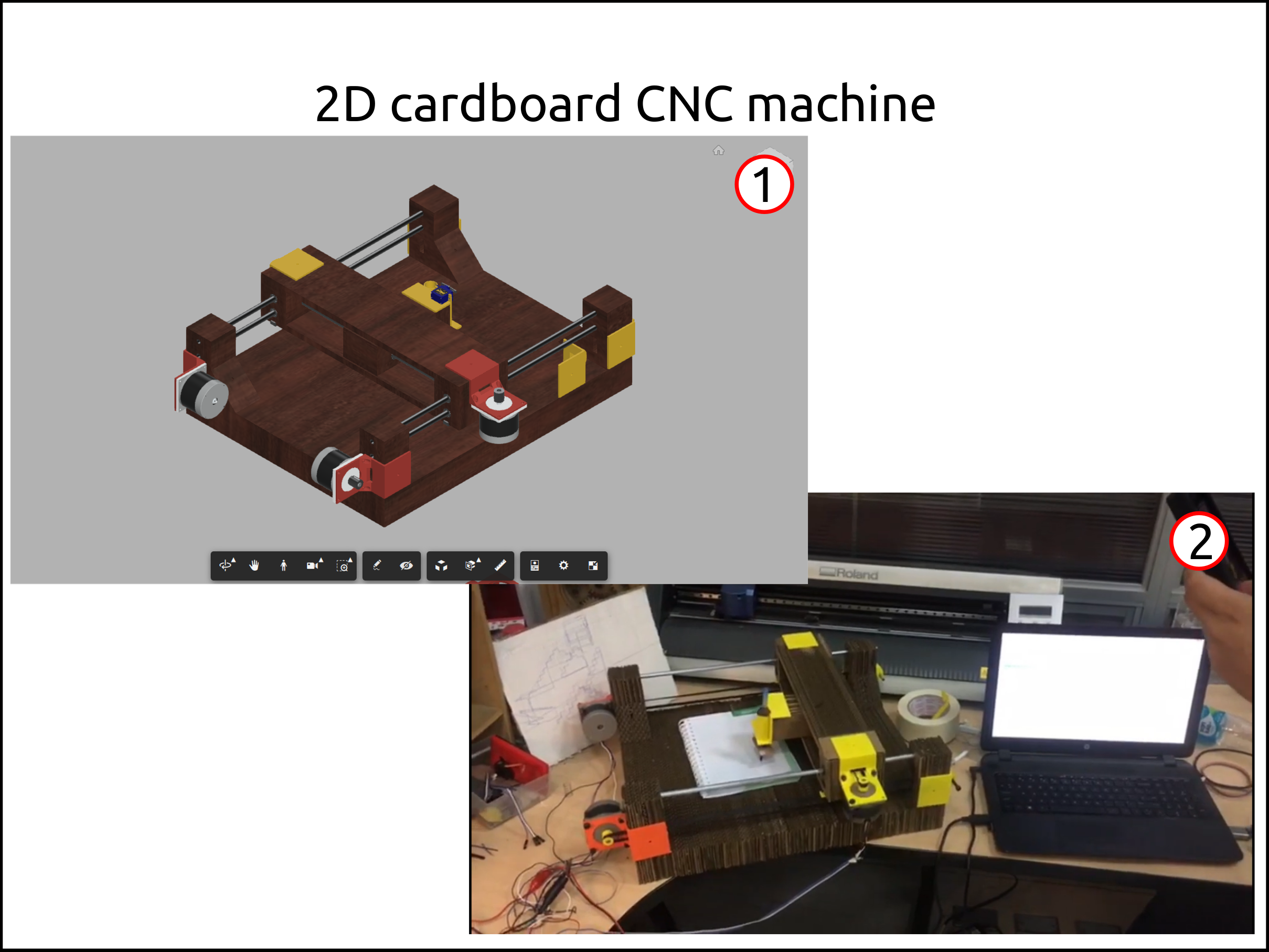
Machine design 2D stacked Cardboard CNC
Who worked building this machine?
In our Fab Lab we were nine people and that is the reason why we did three teams to work independently on a different machine design.
-
Abdon Troche
Step one of the machine building process
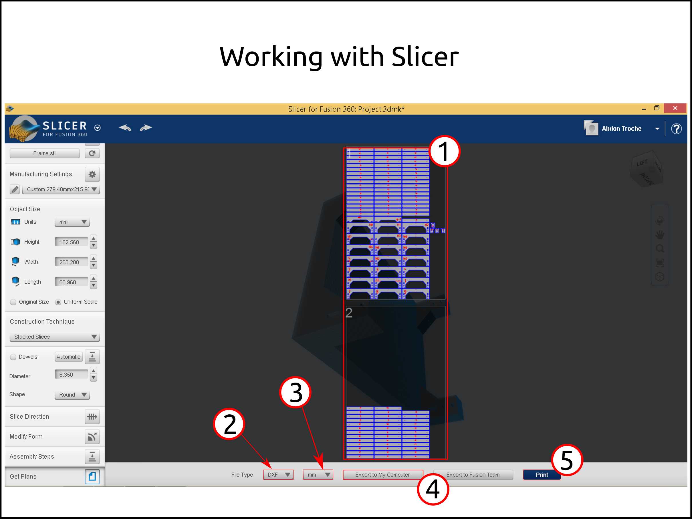
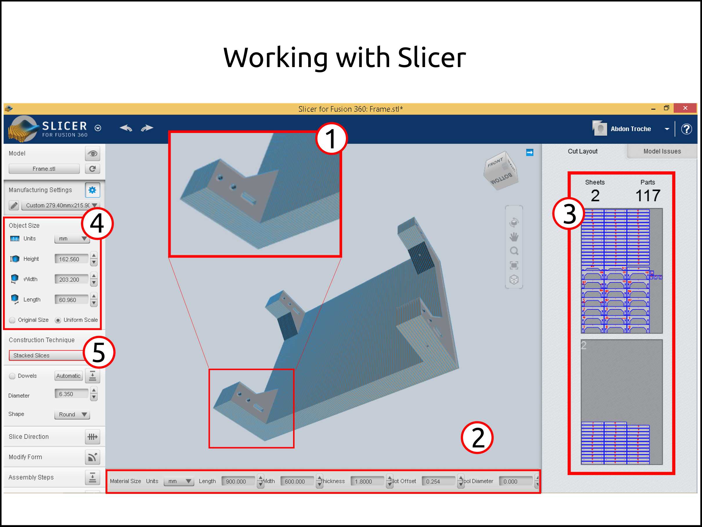
Working with Slicer for Fusion 360
-
Here the software shows you the pages with the the arrangement of the slices in it.
-
In this parameter we can change the output format, I choose DXF.
-
In this parameter we can change the measurement unit, I choose mm.
-
Here we choose were to save, The options are in the cloud or your computer.
-
If you want to see the slices in paper, you can print it with his option.
-
Here I show in detail the tower of the cardboard CNC frame.
-
These are the parameter of the output sheet dimension, clearances and all parameters related to the machine you will to use.
-
Here you can see the quantity of sheets and the quantity of slices.
-
Here you can see the part that you want to slice dimension, here you have to take care because is in inches by default.
-
In this tab you choose the manufacturing method, in this case was stacked slices.
In this video you will see all the process of importing the 3D model to slice it and then to scale it, also to select the manufacturing process and exporting the output files.
Faced problems and solutions working with Slicer
Problems
-
The slices have some error like duplicated geometries and also wrong geometries.
-
The 3D model is imported in inches by default, so my model dimension is not the right one.
Solutions
-
I use the software RDworks V 8.0 to delete the duplicated geometries and replace the wrong geometries with the right one.
-
The solution was to scale it proportional using a known dimension.
Files from Slicer
-
This is the 3DMK file that is the slicer project of the frame
-
This is the 3DMK file that is the slicer project of the X-axis
-
This is the 3DMK file that is the slicer project of the toolhead
Working with RDworks V8.0
Here you will see all the process in RDworks for repairing the Slicer output files, like deleting the duplicated geometries and the convert to PLT to cut it.
Faced problems and solutions working with RDworks
Problems
- The software only works on Microsoft Windows.
Solutions
- During this job all the software I used was on Windows. So I used my dual boot.
Files from RDworks
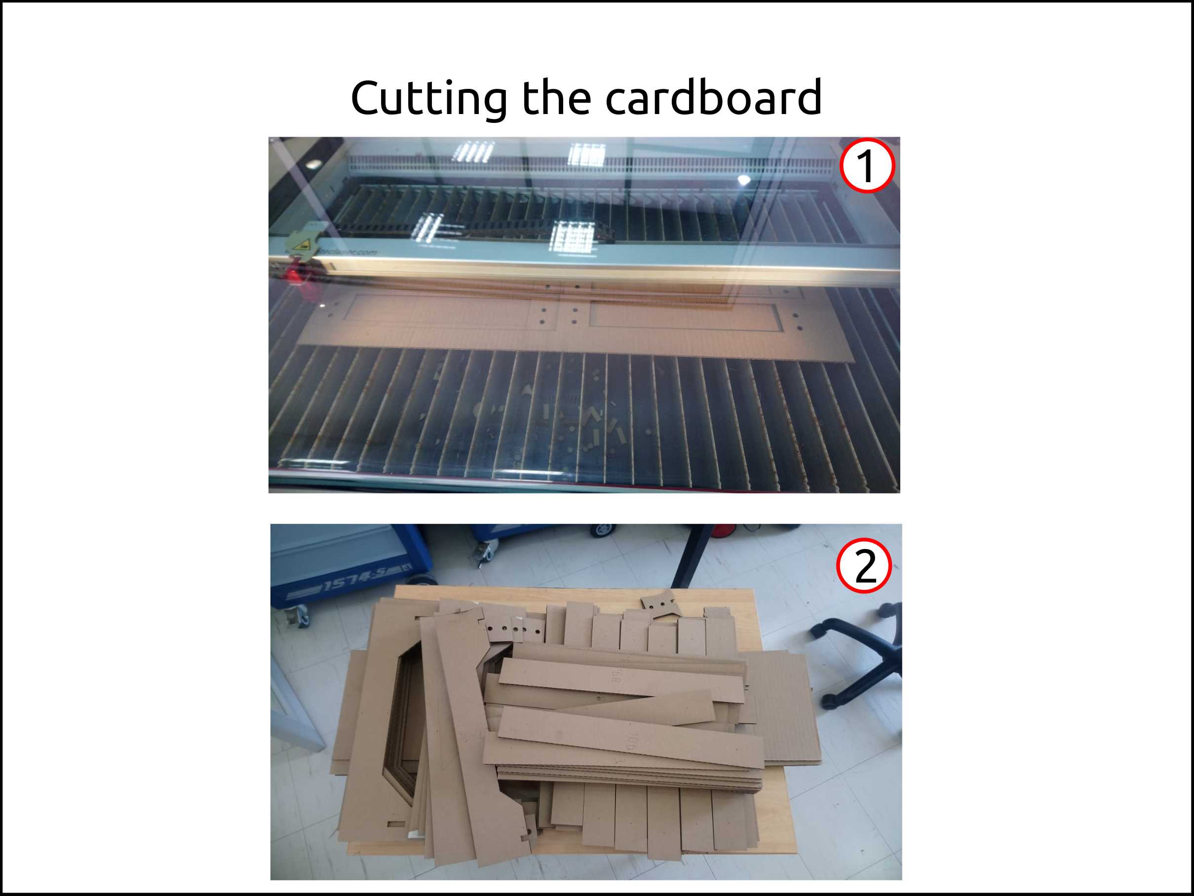
Cutting and assembling the parts of the CNC
This is an example of assembly steps that you can get from the software Slicer that will guide you during the assembly.
I put all the Slicer files where you can see the steps for assembly for every part.
-
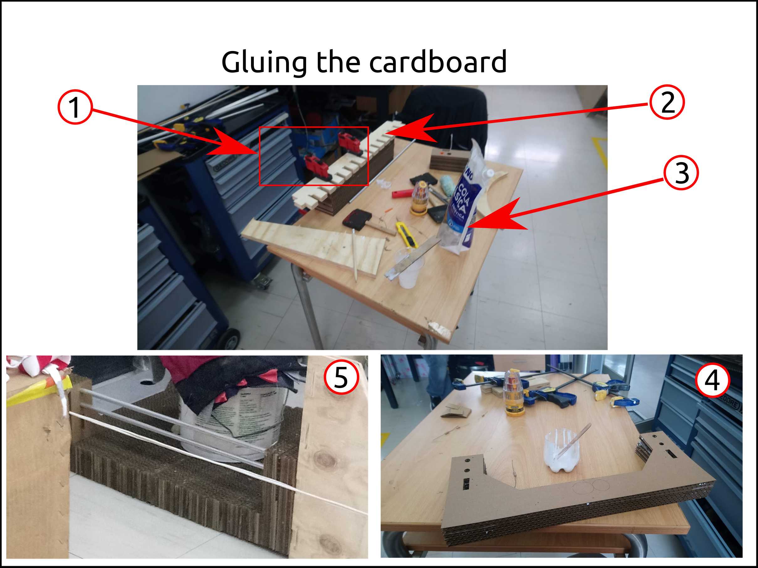
Here we can see the cardboard during the Cutting.
-
Here we see all the parts of the machine that is made in cardboard.
-
These are the clamping tools.
-
This is a piece of plywood to compress the cardboard while the wood glue is drying.
-
This is the wood glue.
-
Here we can see the machine when is assembling.
-
The clamping tool was too short to compress the machine frame so I used what had that wad cable.
Faced problems and solutions assembling the cardboard CNC
Problems
-
The cardboard pieces are not flat enough.
-
The alignment of the slices was not accurate.
Solutions
-
I used masking tape to flat the cardboard in order to cut properly.
-
The flexibility of the cardboard compensate the alignment errors.
Fully assembled machine
Step two of the machine building process
Mechanism of Cardboard CNC
This is the assembled 3D model of the Cardboard CNC that includes only the mechanical parts.
-
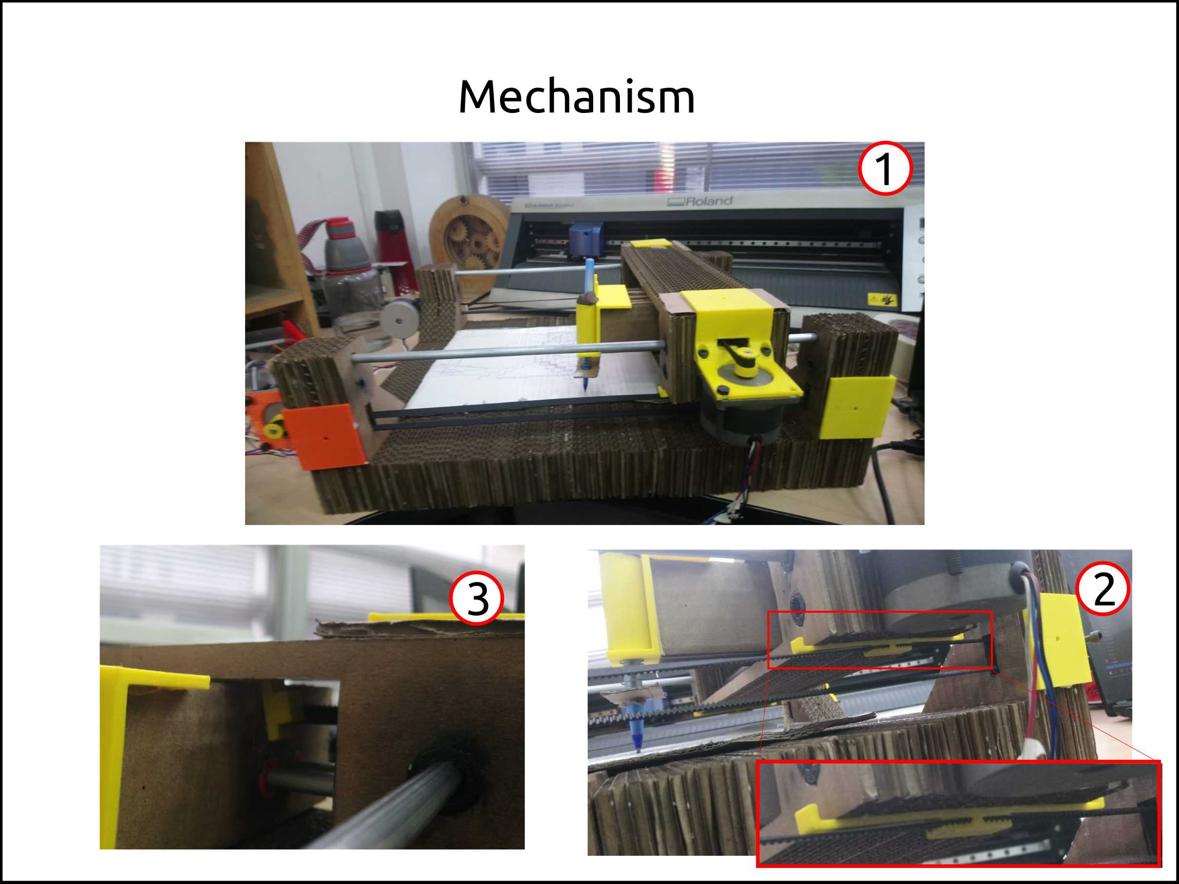
Here you can see the machine full assembled.
-
These are the belt attachment system,that used the shape of the belt to hold it.
-
Instead of using linear bearings we used 3d printed bushing. With a bit of lubricant moves perfectly.
Files of FUSION 360 3D model
Electronics of Cardboard CNC
Fabduino Tecsup 2019
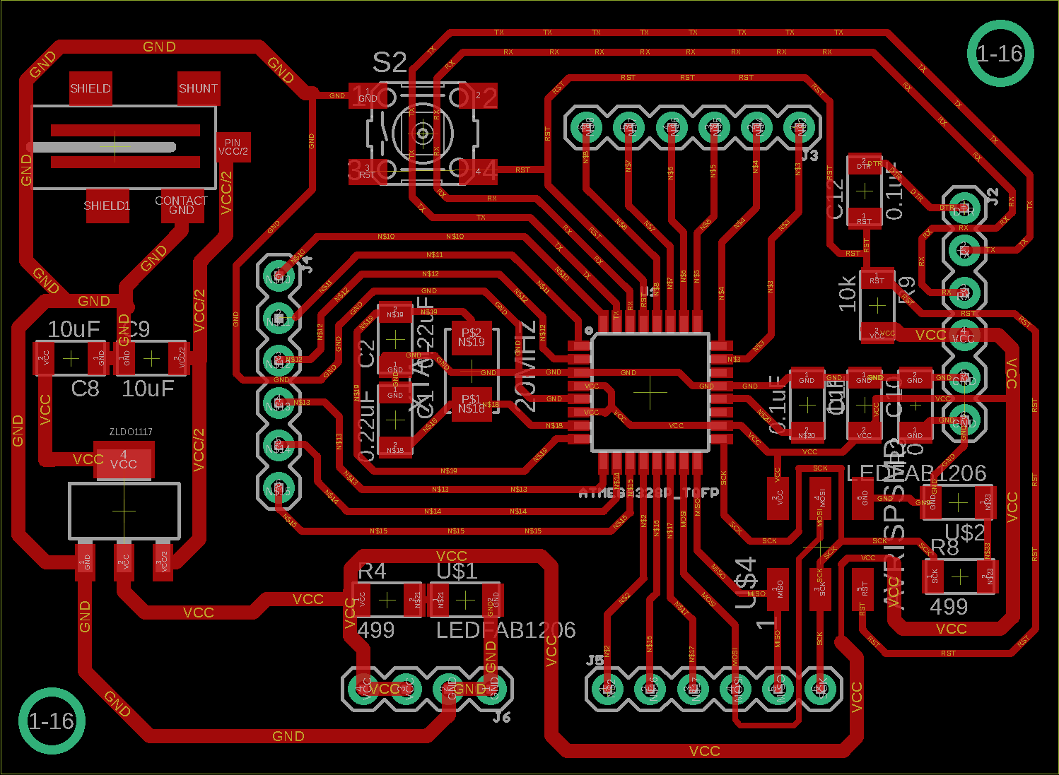
This is the 3D model of the Fabduino that was made with Autodesk Eagle with Autodesk Fusion 360 synchronization.
Files of Fabduino Tecsup 2019
Schematic of the FabDuino

Board of the FabDuino
GRBL Shield for Fabduino Tecsup 2019
This is the 3D model of the FabDuino GRBL Shield that was made with Autodesk Eagle with Autodesk Fusion 360 synchronization.
-
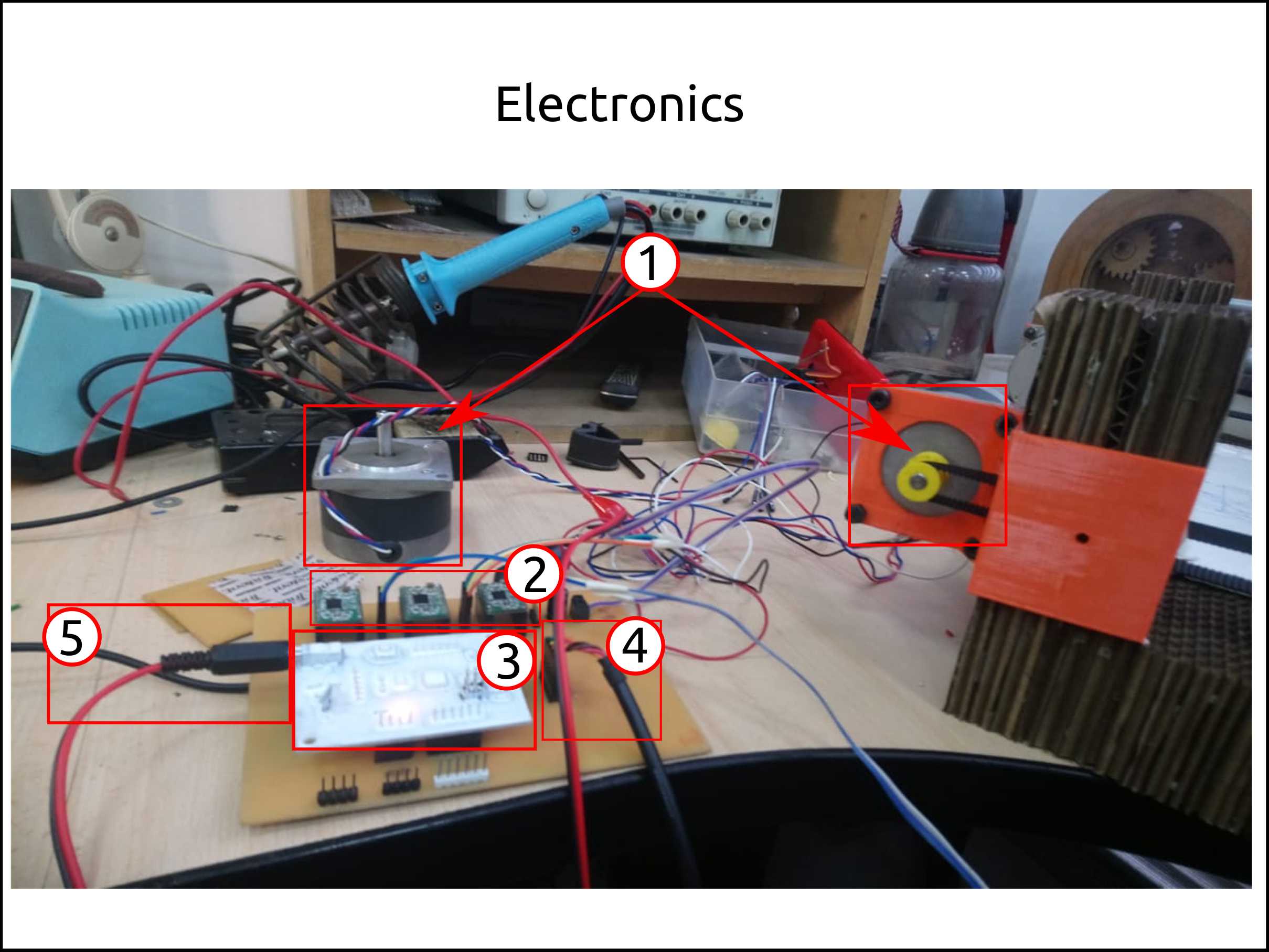
Here you can see the stepper motors that we used.
-
In this case we see the stepper motor drivers used, that are connected on the FabDuino GRBL Shield.
-
This is the FabDuino connected on the FabDuino GRBL Shield. We can see as well that the FabDuino is painted using synthetic aerosol paint, in order to protect the copper layer.
-
This is the FTDI cable that is used for communication with the softare called Universal gcode sender for testing and calibration. Once is calibrated we used our own softare.
-
For connecting to the supply voltage the FabDuino we used this connector called Jack 2.5 mm.
Files of GRBL Shield for Fabduino Tecsup 2019
Schematic of the GRBL Shield for FabDuino
Board of the GRBL Shield for FabDuino
Software of Cardboard CNC
Firmware of the CNC
We used the firmware called GRBL the version 1.1.
To load to the FabDuino we used Arduino IDE.
To control the CNC we used Universal Gcode Sender
Files of software
Gcodes test showed on the video
A demo of the machine running
This is the Demo Video of the machine working.
The machine was tested using the Software called Universal Gcode Sender and a GUI written in Python and Tkinter.