8. Computer controlled machining
-
Group assignment: Test runout, alignment, speeds, feeds, and toolpaths for your machine
-
Individual project: Make (design+mill+assemble) something big.
CNC router and endmills
ShopBot PRSalpha
In this case, is a machine comes with these features:
Fast, closed-loop Vexta alphaStep motors fitted with low-backlash, tapered-hob gear heads on all three axes (two on the X-axis) – alphaStep system monitors motor shaft positions to maintain synchronicity between signal and motion.
Tough precision linear bearings on the moving gantry and hardened steel rails for the x-axis.
Reliable rack-and-pinion power transmission on each axis.
Impressive cutting speeds of up to 600 inches per minute (depending on cutting bit and material) and rapid transit speeds of 1,800 inches per minute.
Step resolution of .0004”.
Positional accuracy of +/- .002”.
Sealed Industrial UL Certified Control Box.
Emergency Stop disconnect switch in the Control Box with integrated and cabled remote Emergency Stop Buttons.
Z-zero Touch-Off Plate and XY Proximity Switches.
ShopBot Control System software to run your CNC.
Dust Skirt ready to connect to your dust collector.
Each new ShopBot tool comes bundled with two powerful software programs to create CNC projects.
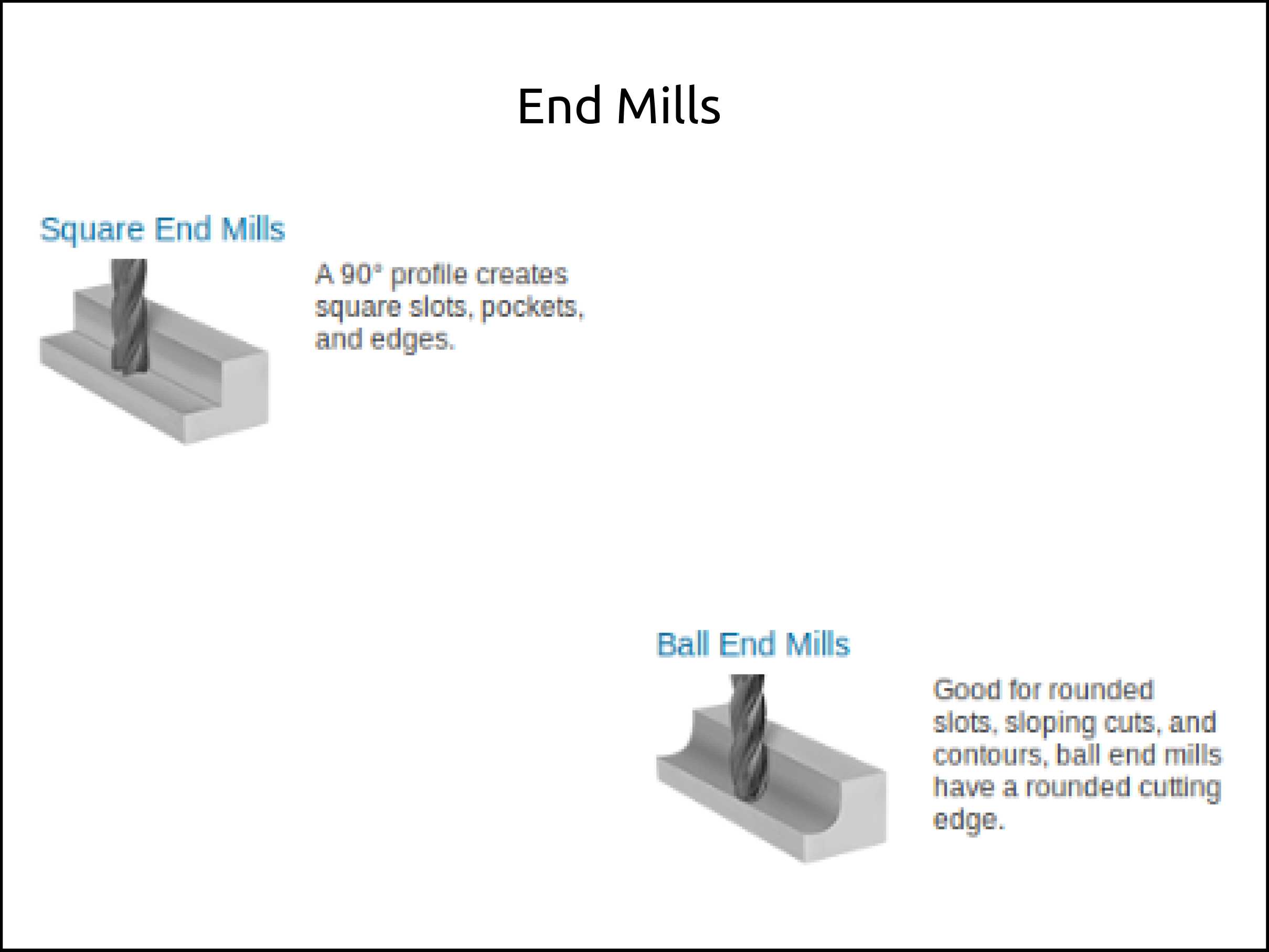
End mills for plastic and Wood
Standard / Square End Mills for Plastic and Wood (PWE) Upcut End Mills
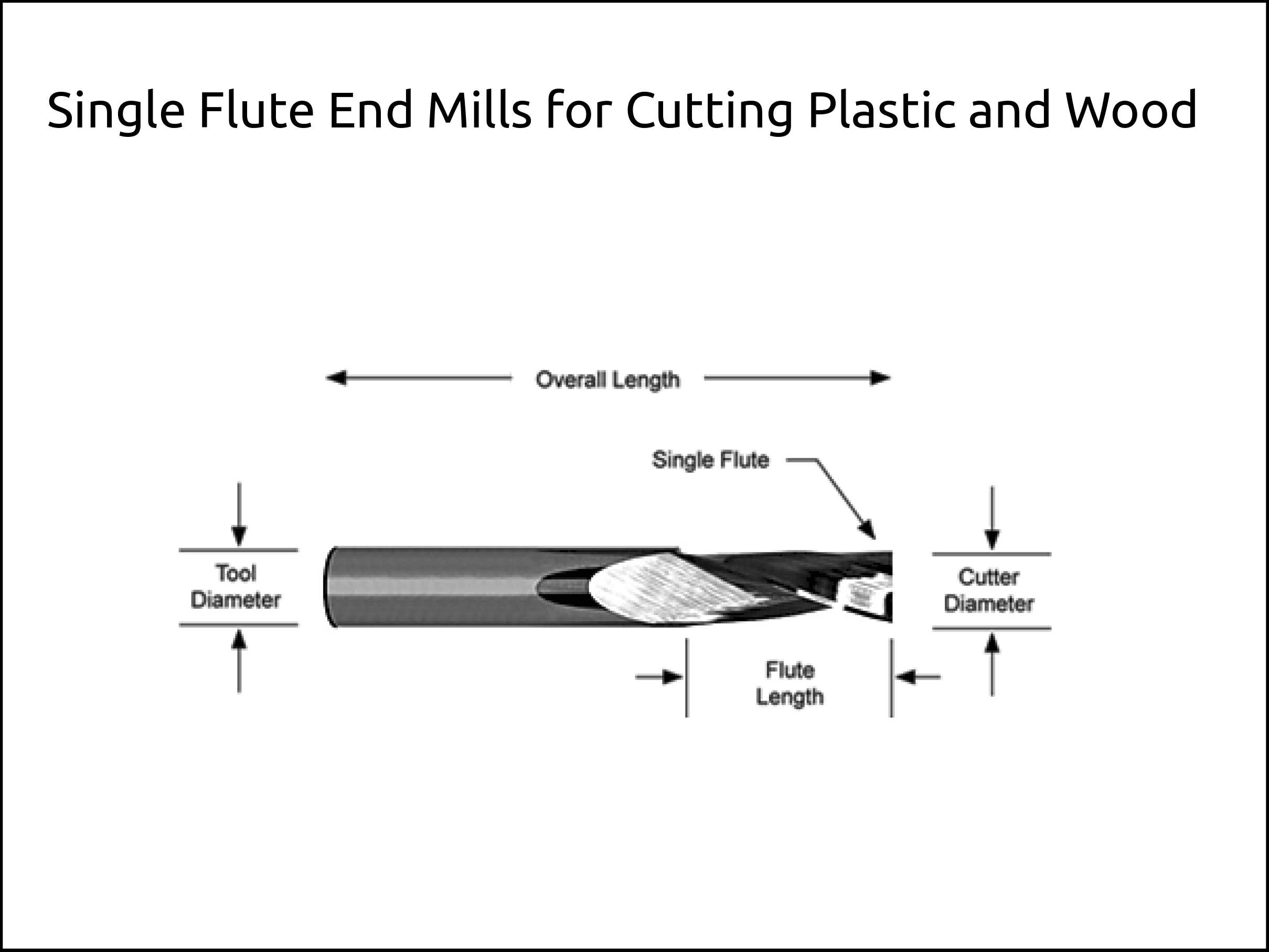
Single Flute End Mills for Cutting Plastic and Wood
-
Single Flute Standard End Mills designed to cut, machine and mill Plastic and Wood.
-
Large single flute allows maximum chip clearance for chip evacuation.
-
Extremely sharp cutting edge produces an excellent surface finish when cutting Plastic and Wood.
-
Center cutting.
-
Slow 20° Helix reduces workpiece lifting and creates a fine finish.
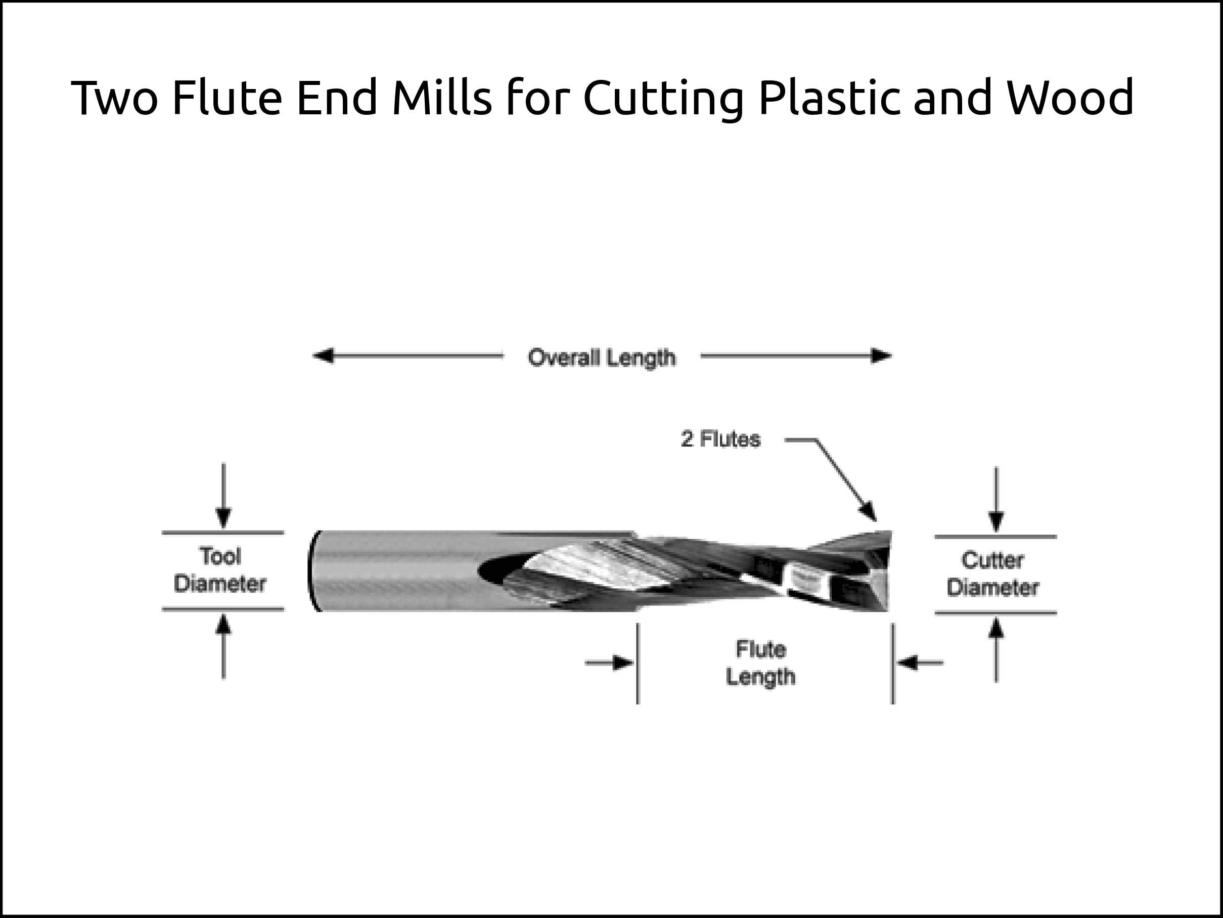
Two Flute End Mills for Cutting Plastic and Wood
-
2 Flute Standard End Mills designed to cut, machine and mill Plastic and Wood.
-
These 2 Flute End Mills allow for higher feed rates than Single Flute End Mills but still provide for a large amount of chip clearance to prevent chips from sticking or packing in the flutes.
-
Extremely sharp cutting edge produces an excellent surface finish when cutting Plastic and Wood.
-
Slow 20° Helix reduces workpiece lifting and creates a fine finish.
-
Center cutting.
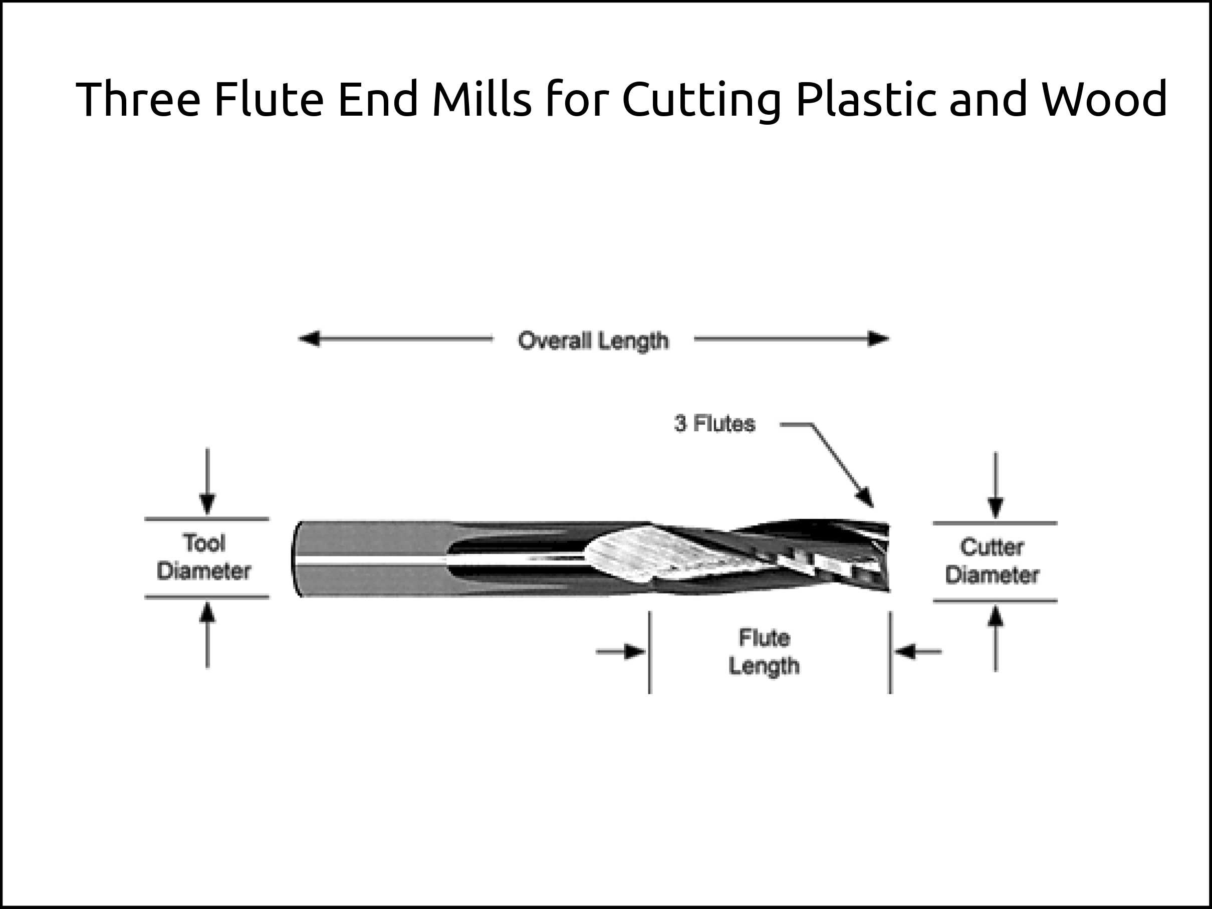
Three Flute End Mills for Cutting Plastic and Wood
-
3 Flute End Mills designed to cut, machine and mill Plastic and Wood.
-
3 Flutes allow the highest feed rates but have less chip clearance space than Single or 2 Flute End Mills.
-
Extremely sharp cutting edge produces an excellent surface finish when cutting Plastic and Wood.
-
Slow 20° Helix reduces workpiece lifting and creates a fine finish.
-
Center Cutting.
Ballnose End Mills for Plastic and Wood (PWB) Upcut End Mills
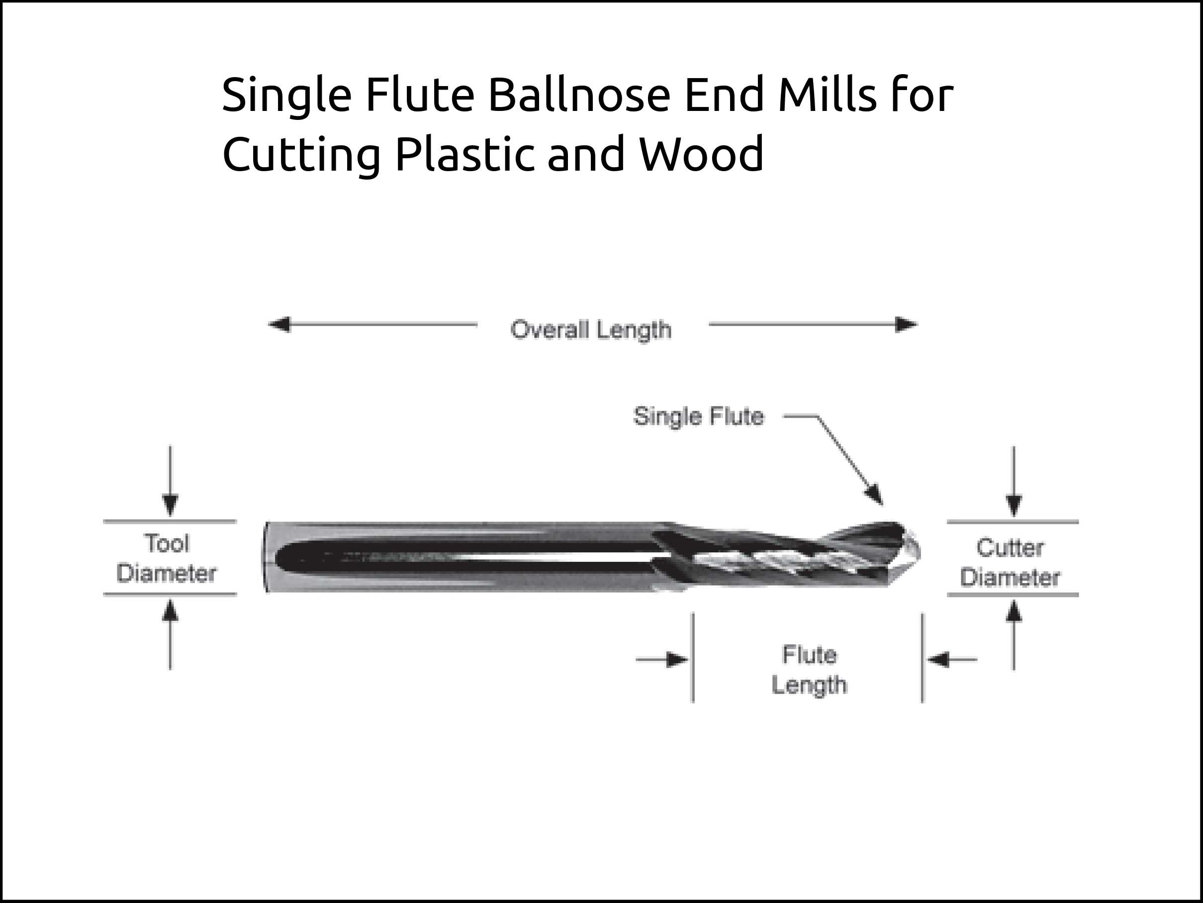
Single Flute Ballnose End Mills for Cutting Plastic and Wood
-
Single Flute Ballnose End Mill to cut, machine and mill Plastic and Wood.
-
Large Single Flute allows maximum chip clearance for chip evacuation.
-
Extremely sharp cutting edge produces an excellent surface finish when cutting Plastic and Wood.
-
Slow 20° Helix reduces workpiece lifting and creates a fine finish.
-
Center cutting.
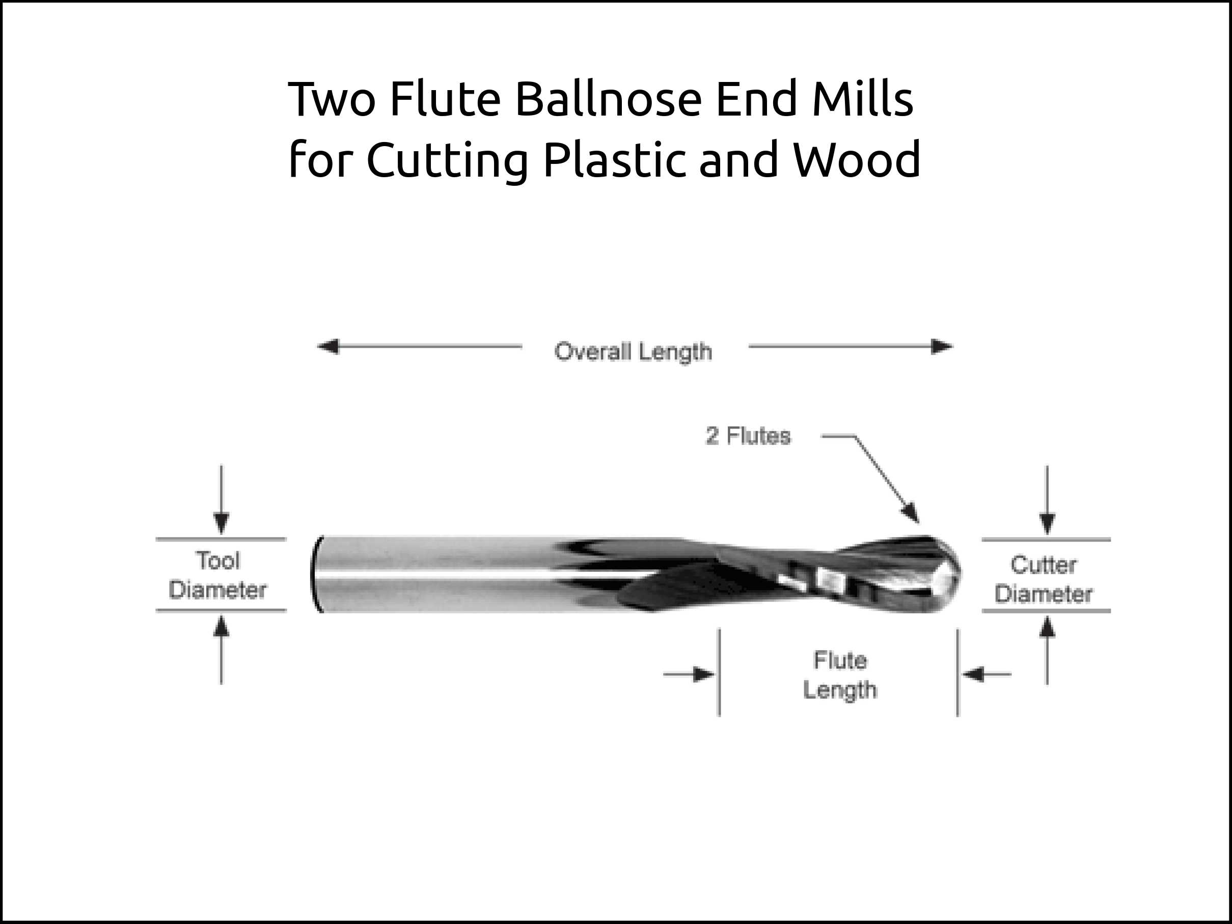
Two Flute Ballnose End Mills for Cutting Plastic and Wood
-
2 Flute Ballnose End Mill designed to cut, machine and mill Plastic and Wood.
-
These 2 Flute End Mills allow higher feed rates than Single Flute End Mills but still provide for a large amount of chip clearance to prevent chips from sticking or packing in the flutes.
-
Extremely sharp cutting edge produces an excellent surface finish.
-
Slow 20° Helix reduces workpiece lifting and creates a fine finish.
-
Center cutting.
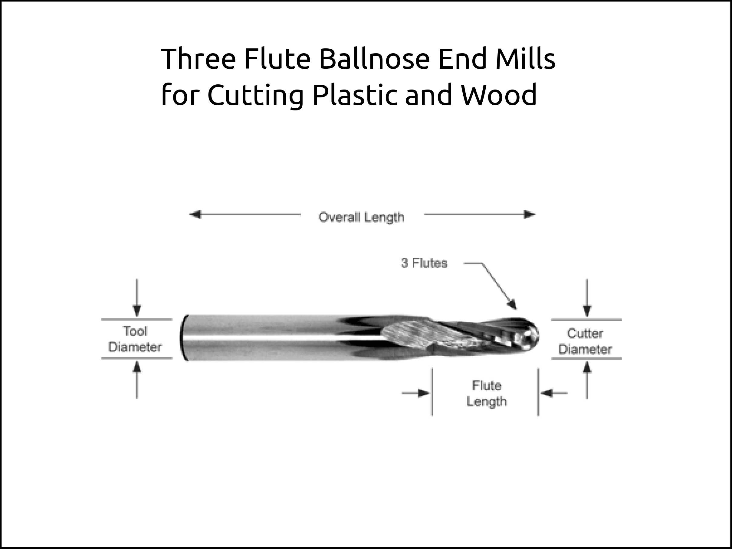
Three Flute Ballnose End Mills for Cutting Plastic and Wood
-
3 Flute Ballnose End Mills cut, machine and mill Plastic and Wood.
-
These 3 Flute End Mills allow the highest feed rates but have less chip clearance space than Single or 2 Flute End Mills.
-
Extremely sharp cutting edge produces an excellent surface finish.
-
Slow 20° Helix reduces workpiece lifting and creates a fine finish.
-
Center cutting.
Downcut End Mills for Plastic and Wood (PWD) Downcut End Mills
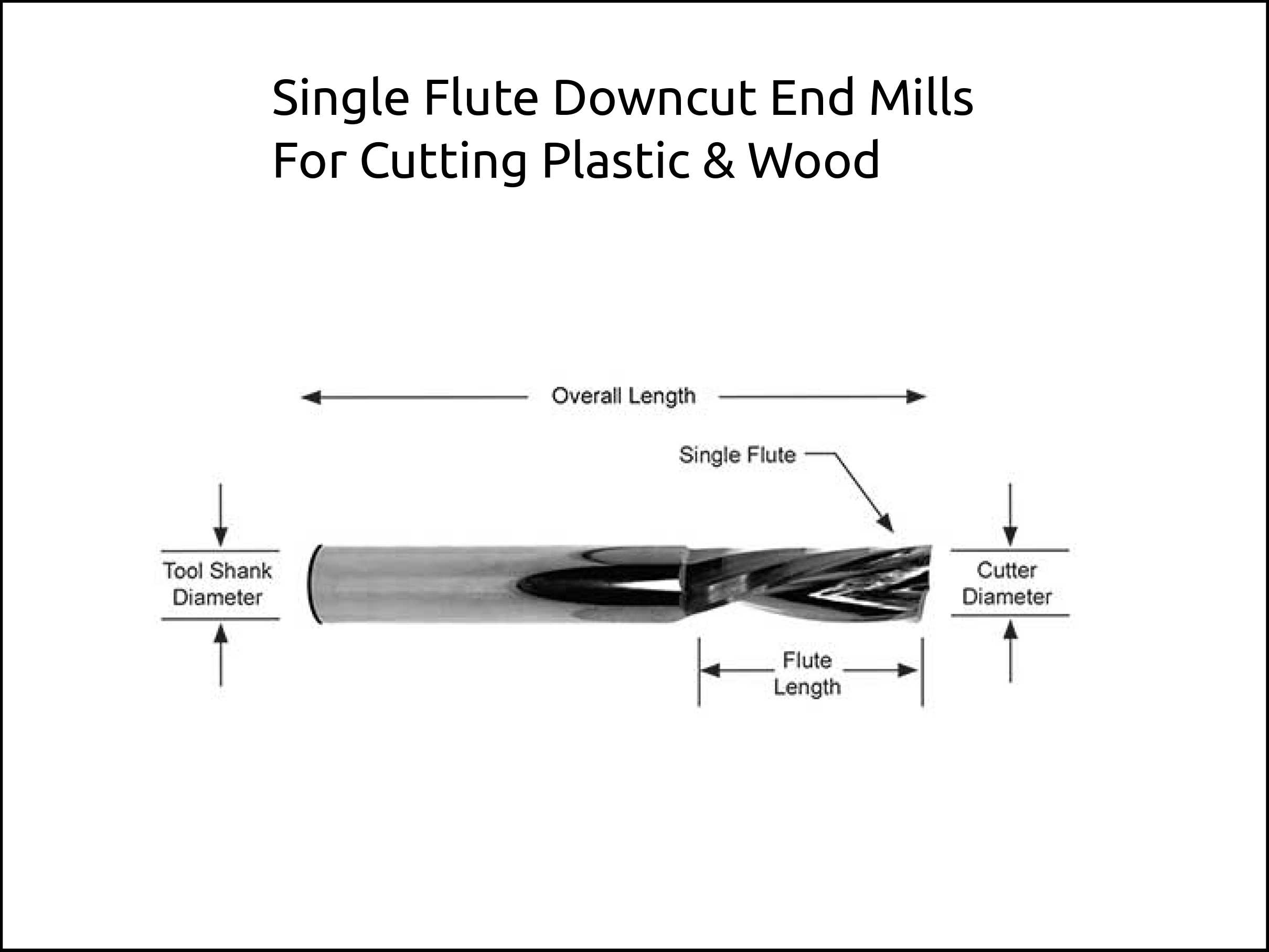
Single Flute Downcut End Mills For Cutting Plastic & Wood
-
Downcut Single Flute End Mills for cutting Plastic and Wood.
-
Right-hand cut with a left-hand spiral.
-
20° helix flute pushes burrs downward to improve top edge appearance and prevents workpiece lifting on vacuum chucks.
-
Extremely sharp cutting edge allows high feed rates while producing an excellent surface finish.
-
Center cutting for straight plunging or ramping down into workpiece.
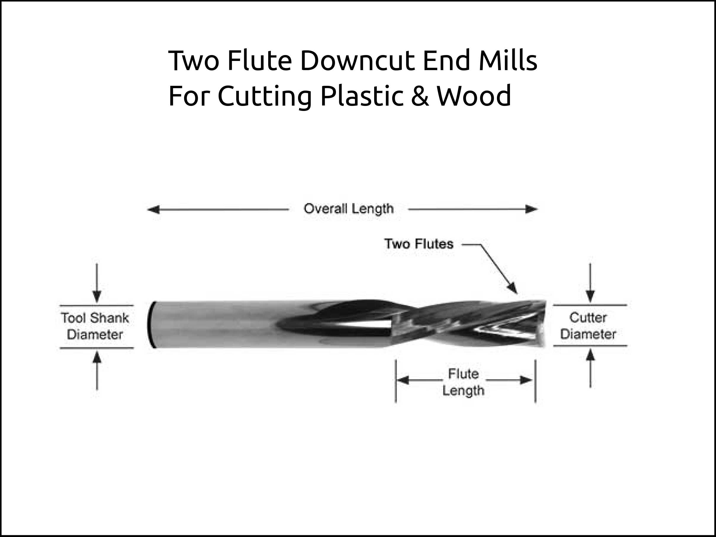
2 Flute Downcut End Mills For Cutting Plastic & Wood
-
2 Flute Downcut End Mills for cutting Plastic and Wood.
-
Right-hand cut with a left-hand spiral.
-
20° helix flute pushes burrs downward to improve top edge appearance and prevents workpiece lifting on vacuum chucks.
-
Extremely sharp cutting edge allows high feed rates while producing an excellent surface finish.
-
Center cutting for straight plunging or ramping down into workpiece.
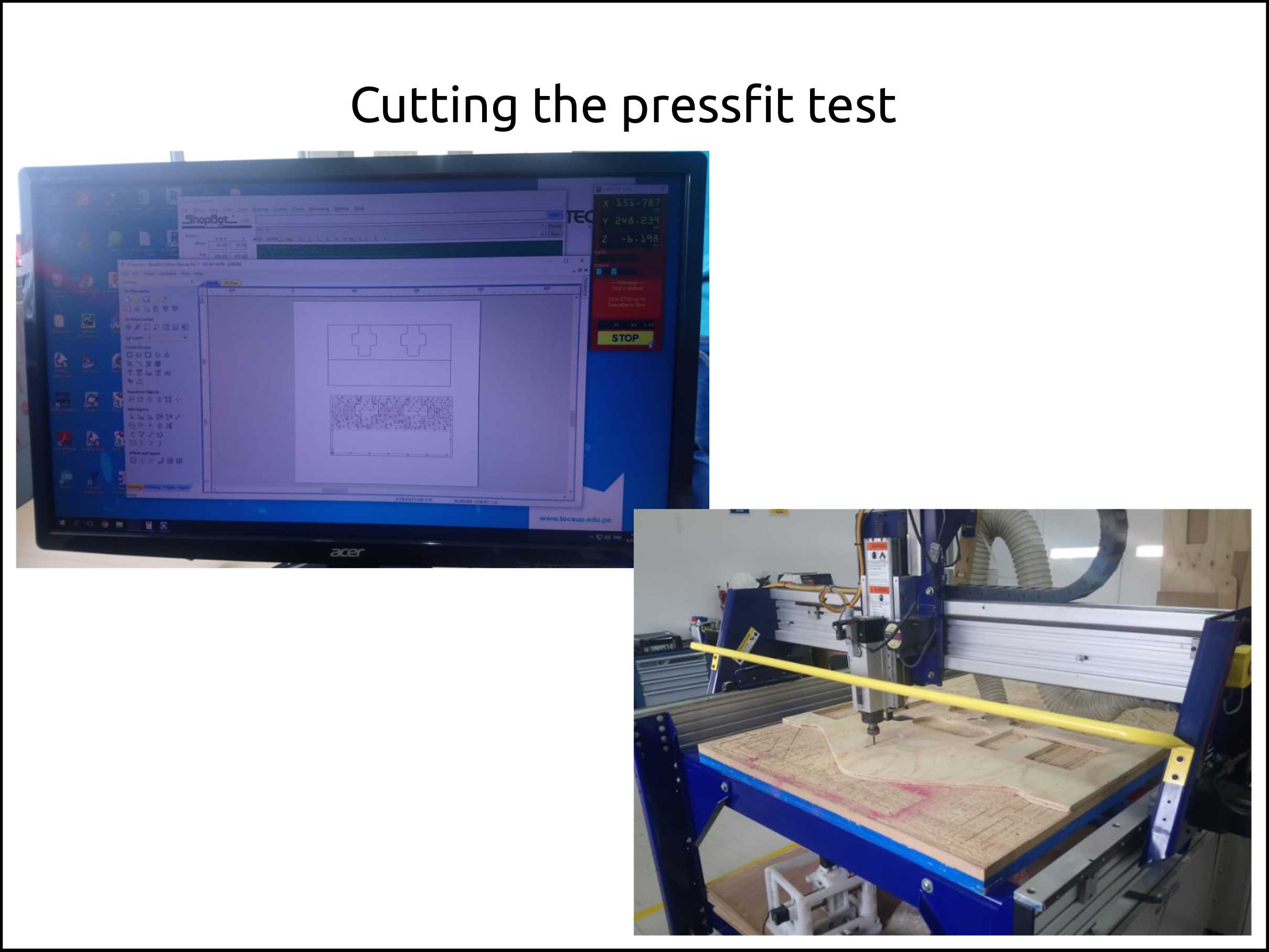
Press-fit test
The purpose of this test was to find the cut pieces will need some clearance in order to fit tight.
The result of this test was that a difference at the laser cutting you do not need clearance.
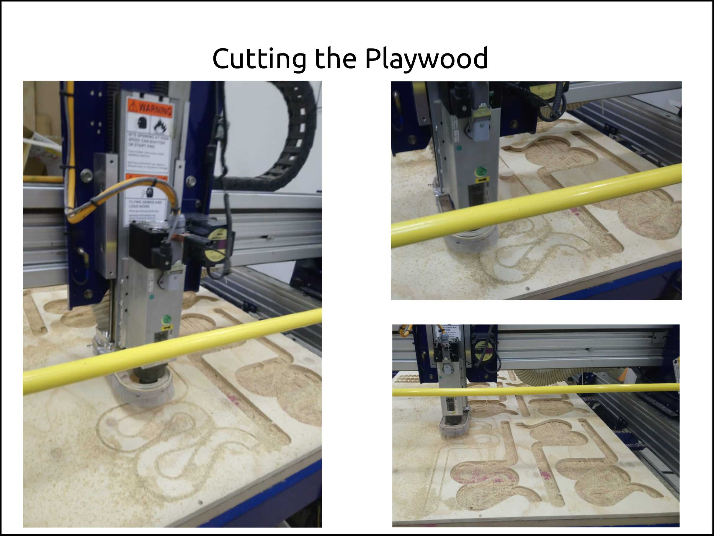
Here I show the cutting process.
-
Here we can see the model that was cut. The problem was that I did not mirror the drawing, so it could not fit for the first time.
-
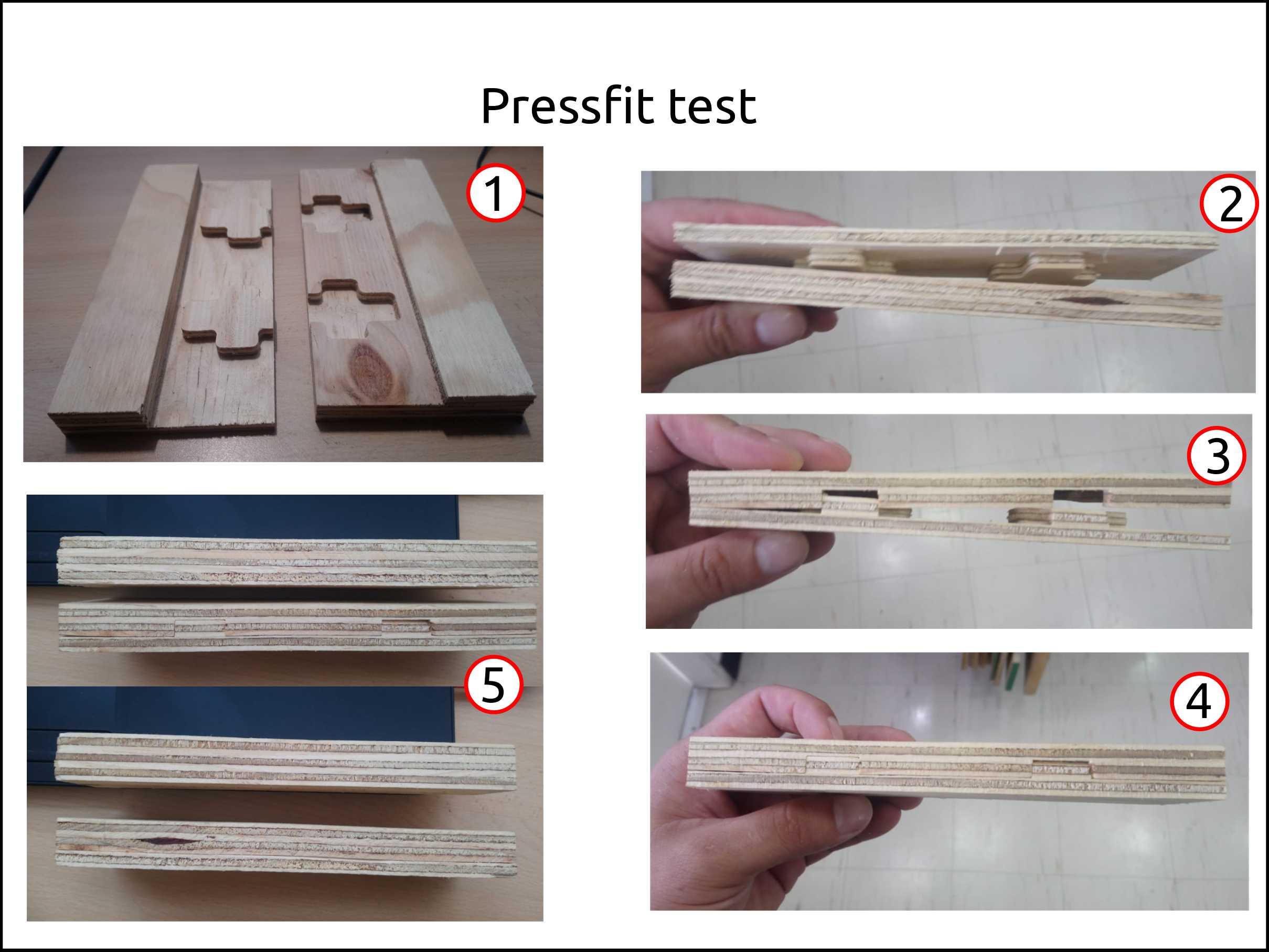
I decided to cut the section that it does not fit in order to gain time and test the press-fit anyways.
-
Here we can appreciate the test is fitting using some force.
-
The fitting is complete here.
-
We can appreciate that the fitting works very well, that even we can not see apparent gaps between the two parts.
Faced problems and solutions working on the press-fit test
Problems:
-
I did not mirror the drawing so it does not fit.
-
During the design is important to see what is the result in the 3D view, and drawing using LibreCAD is difficult to see it.
Solutions:
-
I cut the part that did not fit and continued the test.
-
The solution was to move to Fusion 360 to gain agility during the designing.
Files of LibreCAD
Doing a chair
Designing the chair in Fusion 360
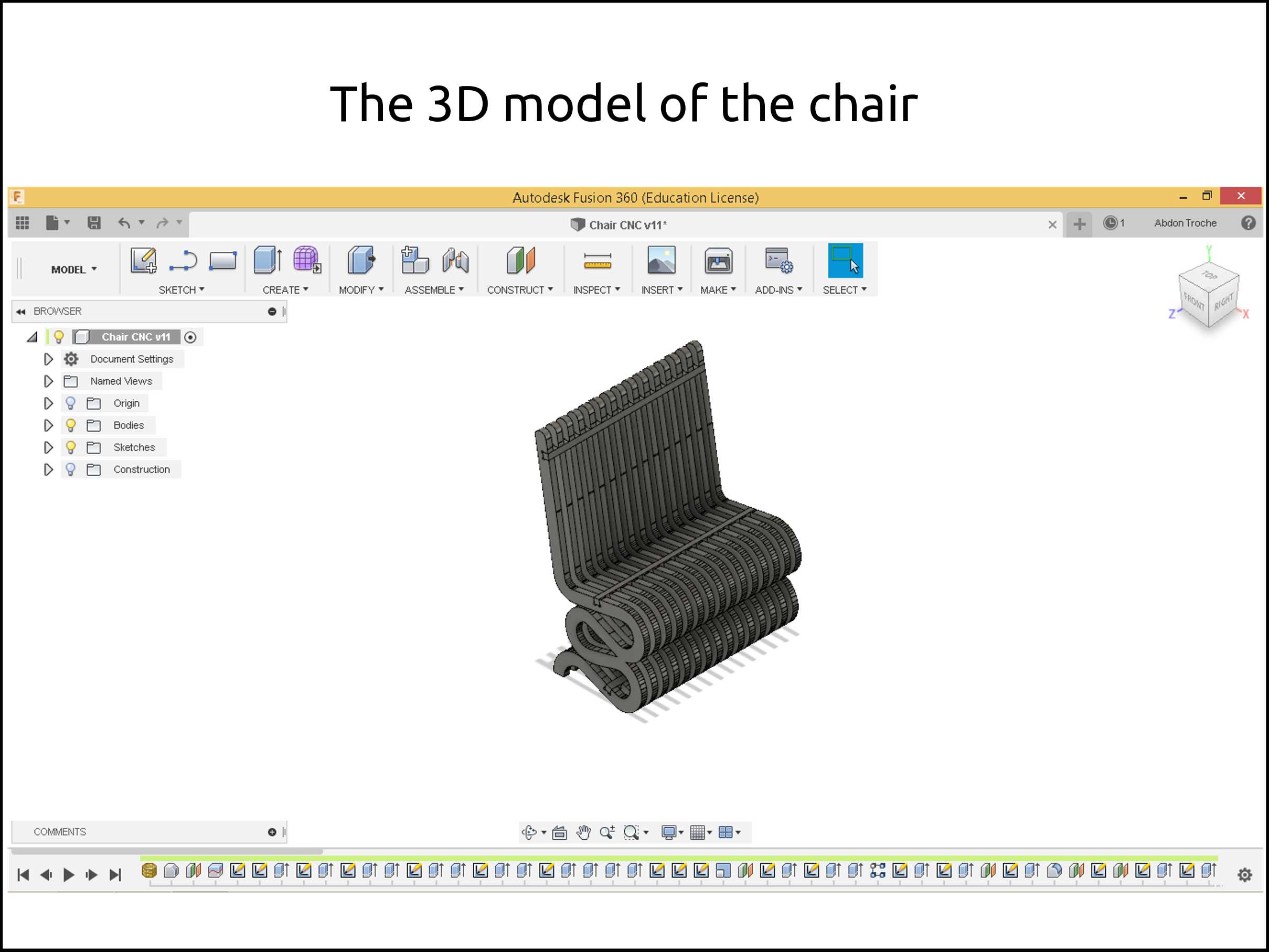
The idea was to fabricate furniture that was designed for other manufacturing technique using the CNC router. So I choose a 3D printed chair and convert the model to a design that I can cut.
The chair that inspired me I found in thingiverse.
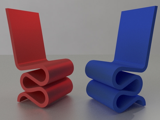
First of all, I downloaded the 3D model in STL and then converted to solid, after that, I copied the shape and modified according to my needs.
At the beginning, I wanted to make the chair full of plywood layers but that going to take too much time to cut it and also too much material. The point is that in the lab we are nine-person doing the Fab Academy so we were limited by cutting time and also the amount of material.
Because of all the reason mentioned above I did the chair like in the image.
Faced problems and solutions doing the 3D model of the chair
Problems:
-
It took me too much time deciding what to design and build.
-
My first design full of layers of plywood, but it does not fit in one only.
Solutions:
-
I decided to take a model as inspiration and proceed.
-
The solution was to put alternated the layers with separators.
Files of Fusion 360
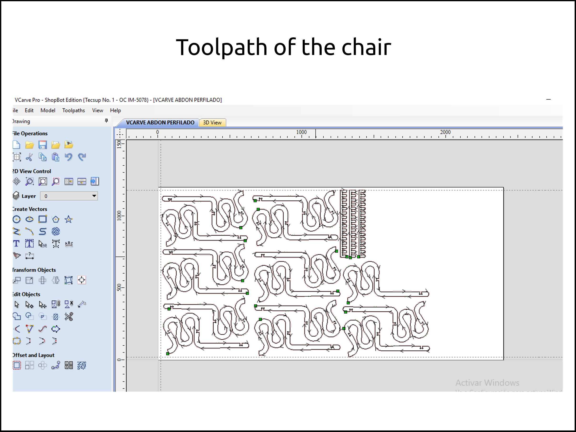
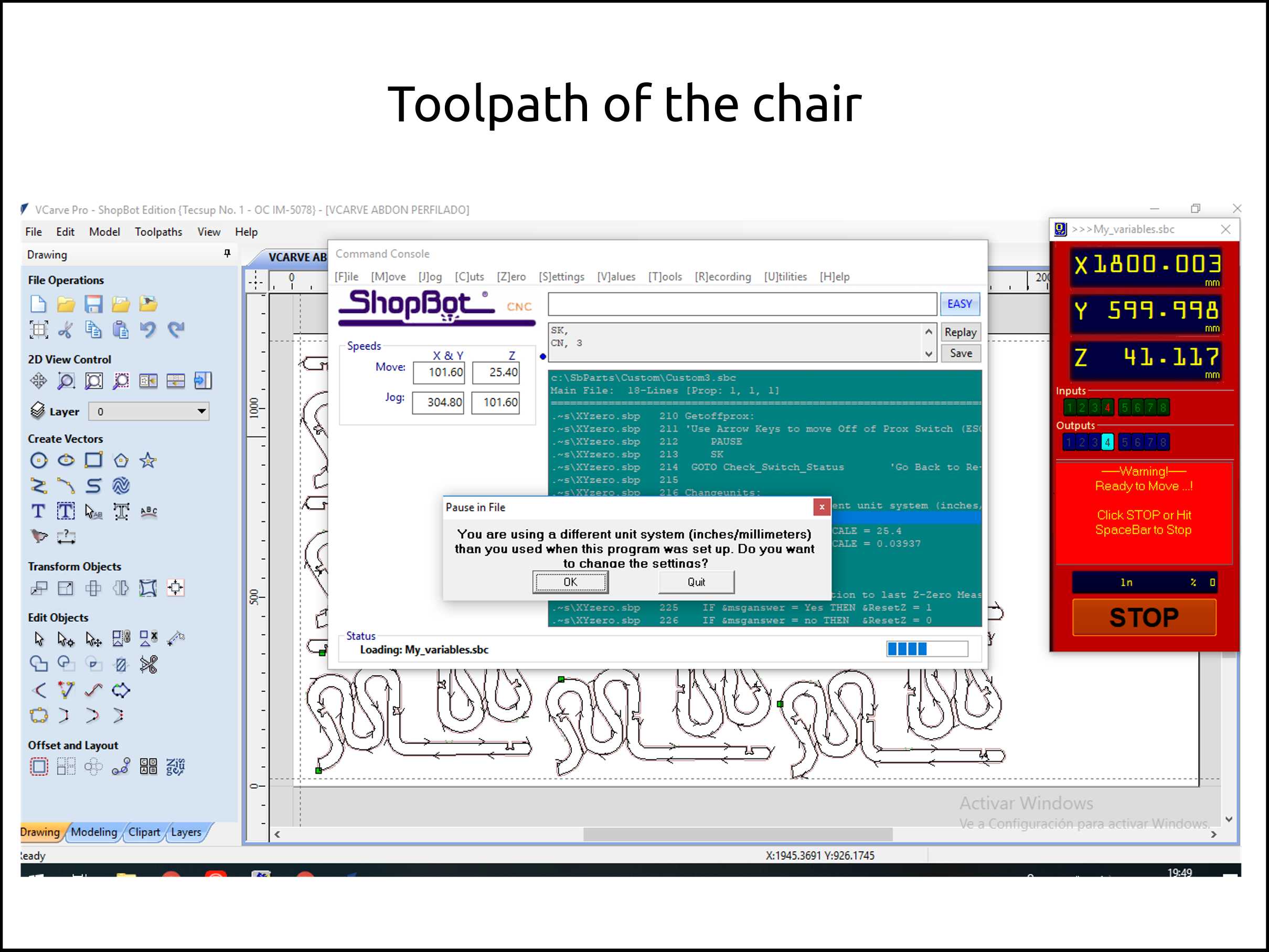
Creating the toolpaths of the chair with VCarve ShopBot edition
We see here the creation of the toolpath. And the green dots are tabs that prevent the part moves during the cutting. The arrow tip means the direction of the cutting. Is really important to verify that the spaces of the slots are bigger than the tool diameter SlotSpace>ToolDia.
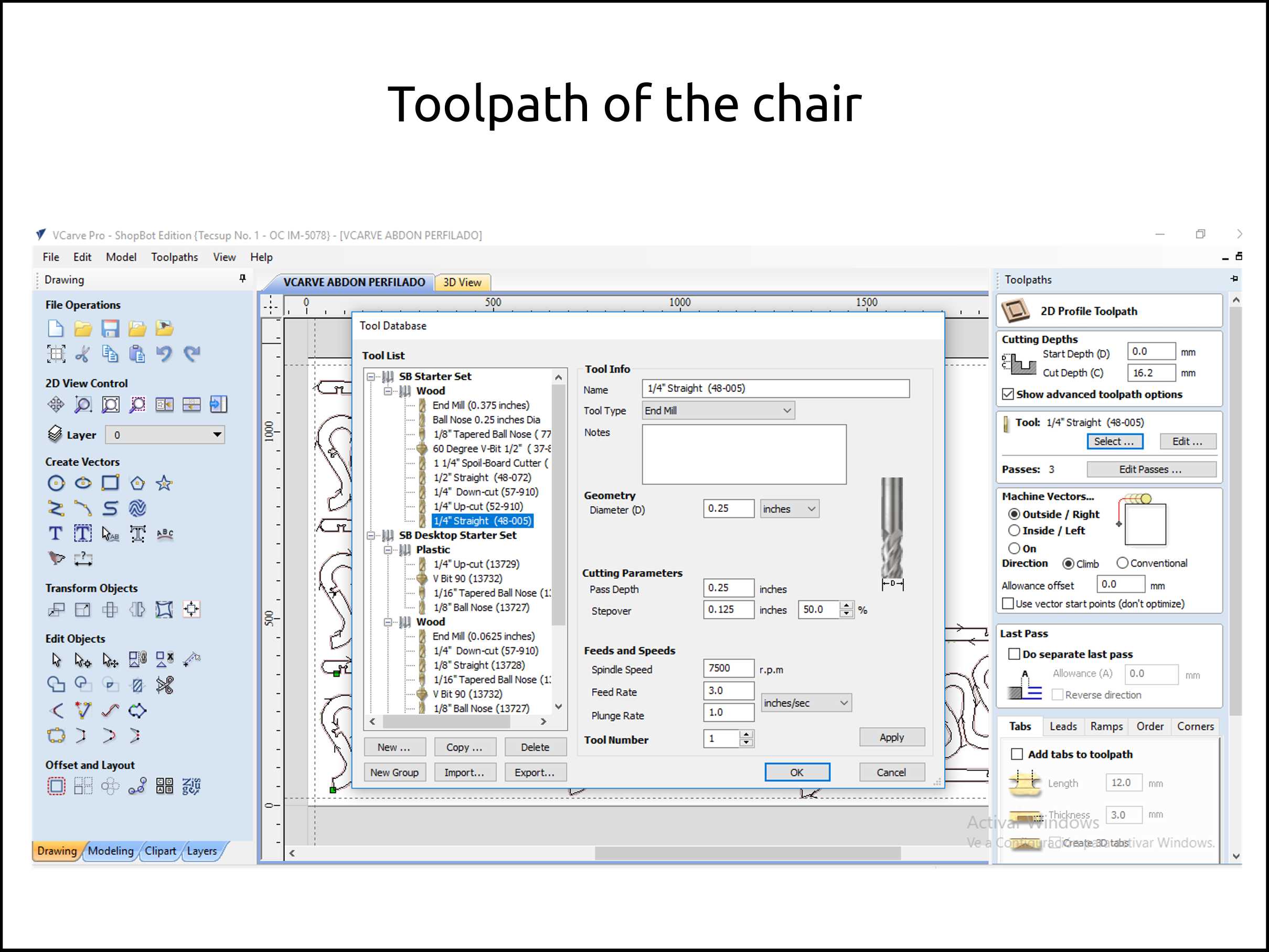
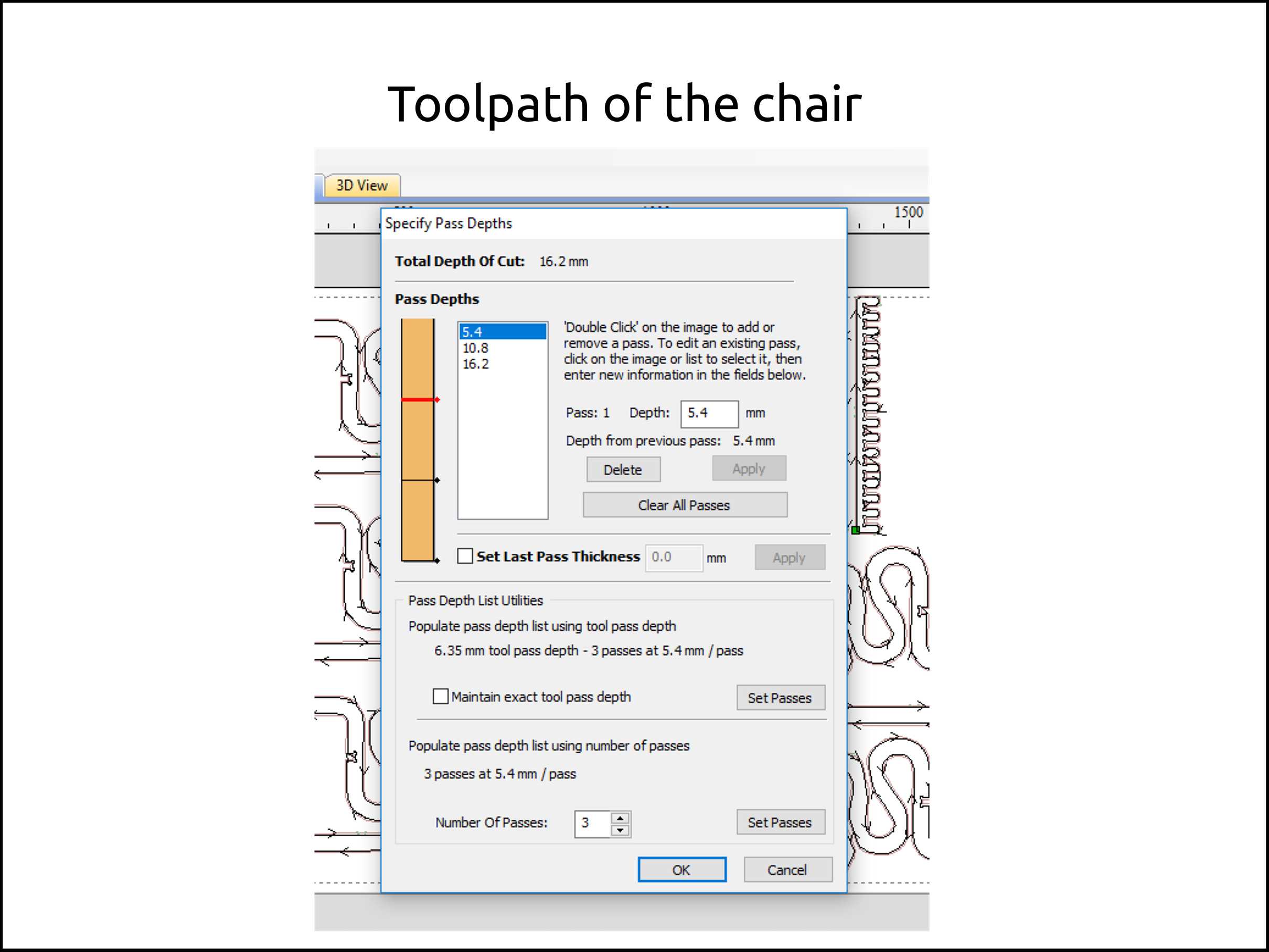
In this case, I used a 1/4” flat, uppercut tool. Here I show the parameters that I used for cutting the plywood.
It is an excellent tool Fablab Speed and Feeds Calculator that allows you to choose the right feed speeds for the material you want to cut in order to get better results.
-
Here we can see the current position of the tip of the tool.
-
Here the software shows the codes that are sending line by line.
-
Here we can see the toolpath.
-
This is the VCarve toolbox.
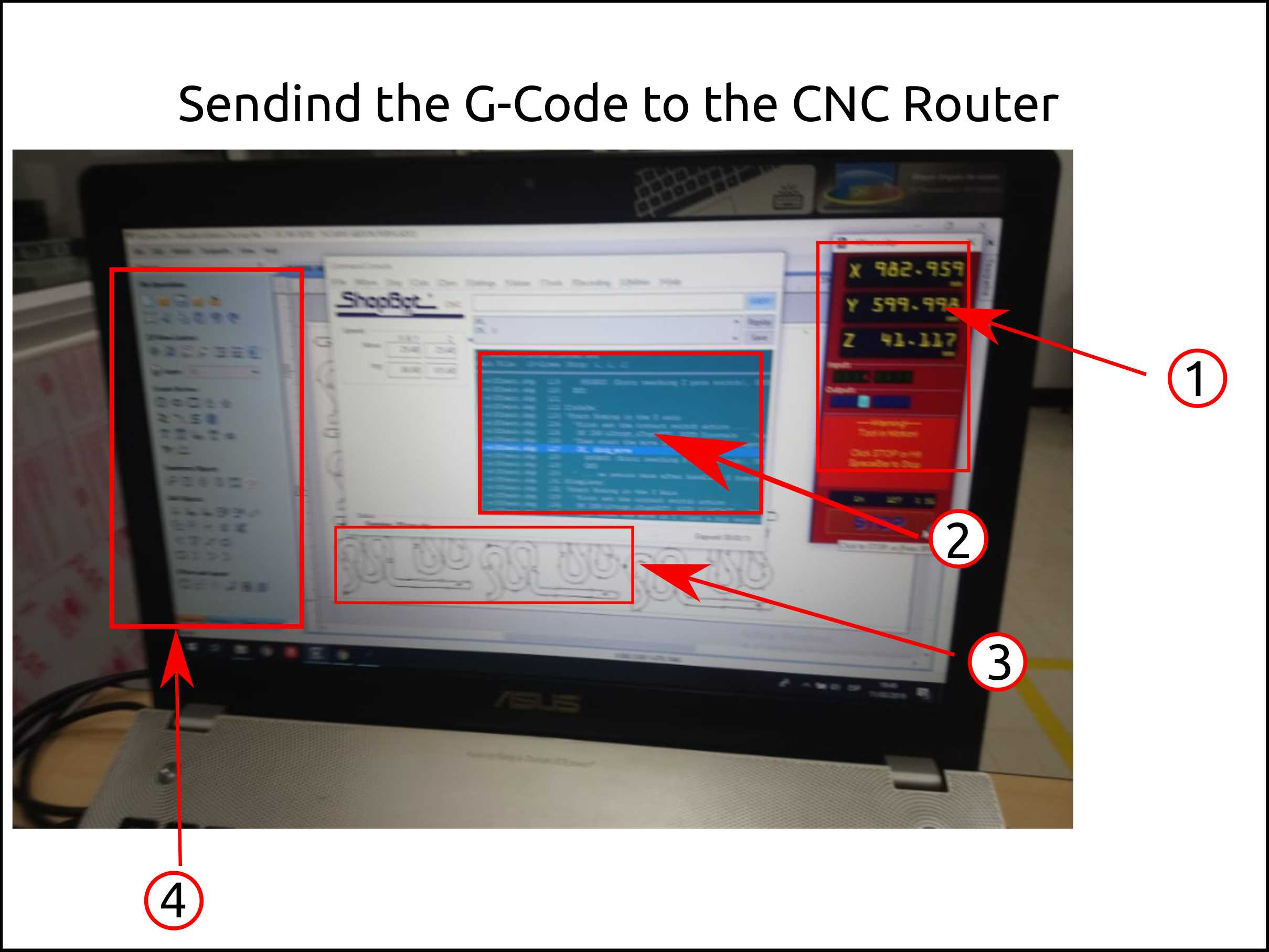
Once the toolpath G-code was generated is time to send to the CNC machine through the CNC software called ShopBot Control Software.
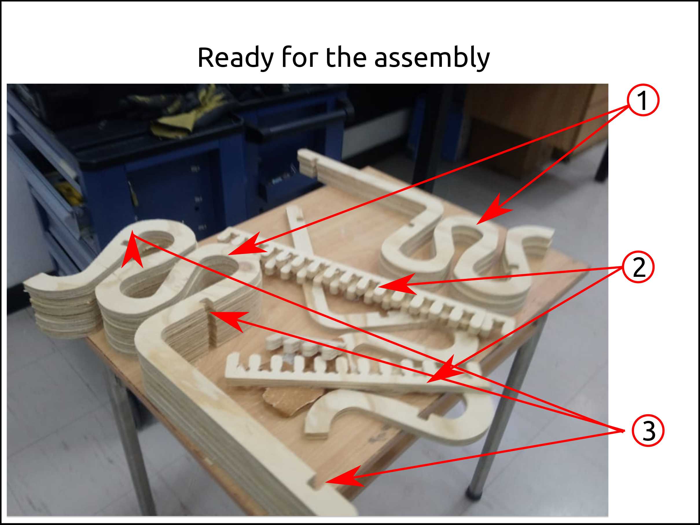
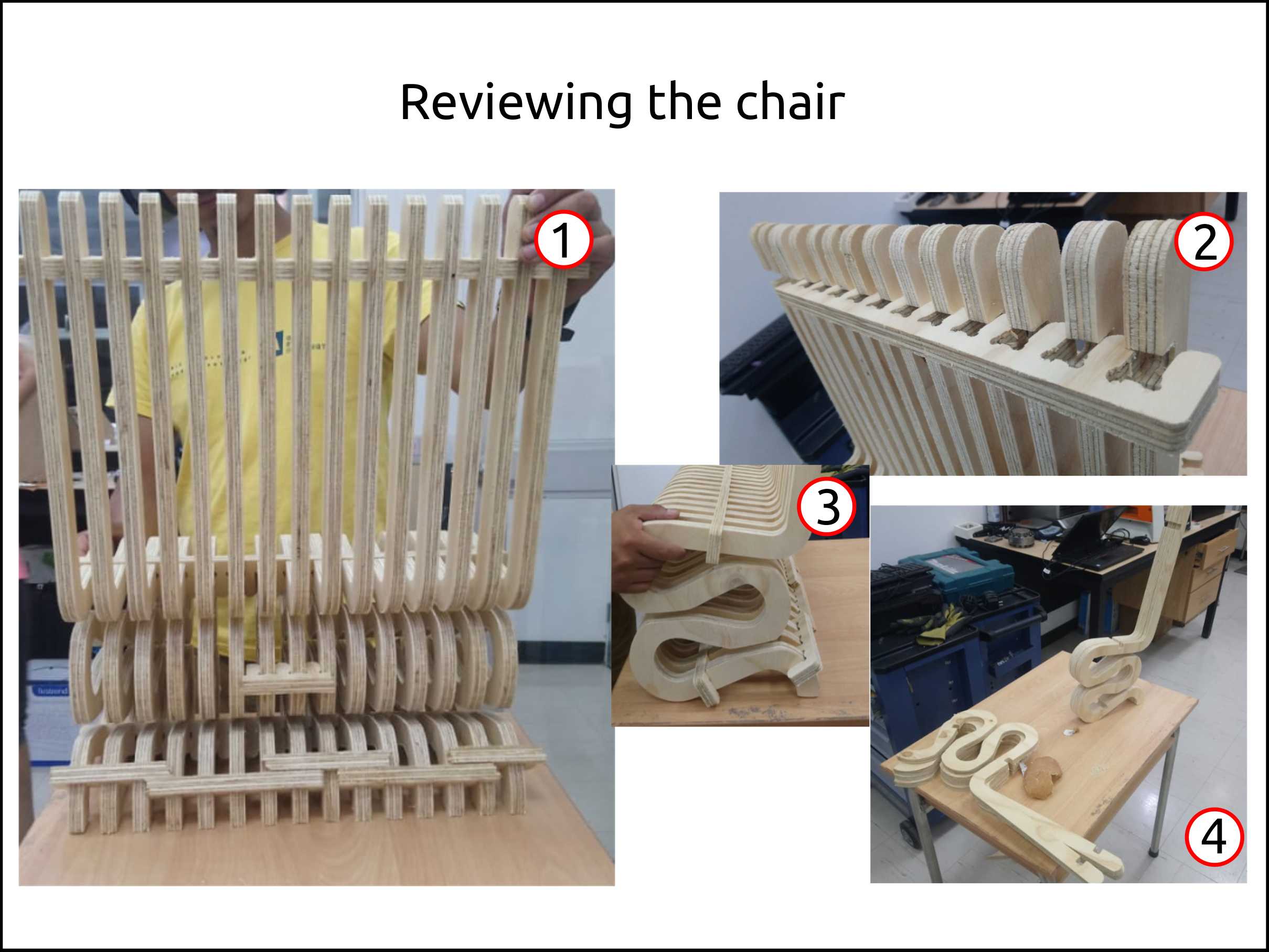
-
These are the layers that will be stuck with the separators.
-
This is the separators.
-
Here we see the slot where the separator fits.
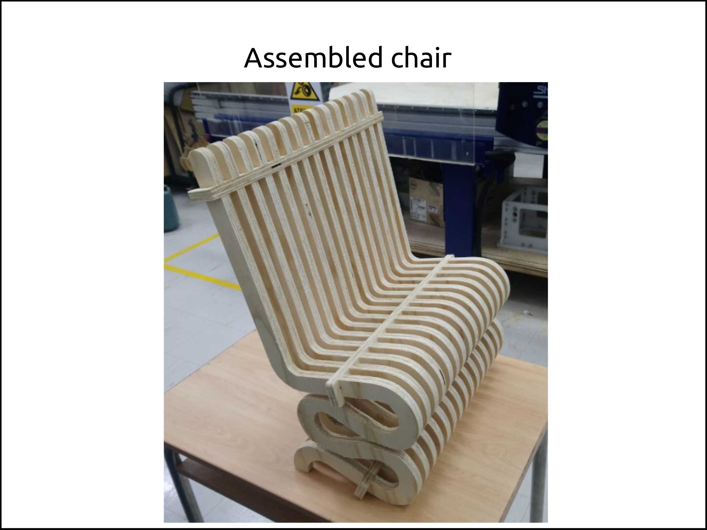
-
This is the fully assembled chair.
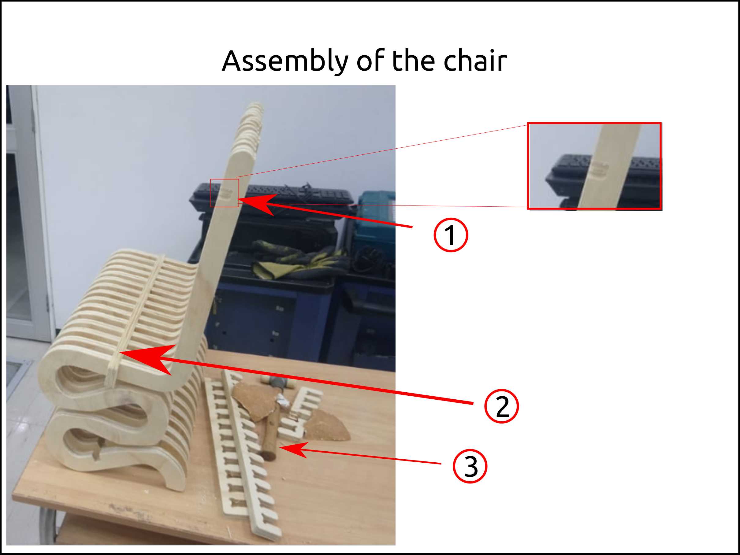
-
This shows the moment when I fitting the separator.
-
This is the side view of the chair.
-
Here we can see the stability of the layers.
Here I show the failure that I got because I did not put enough tabs and the piece vibrates so the got debilitated because of that.
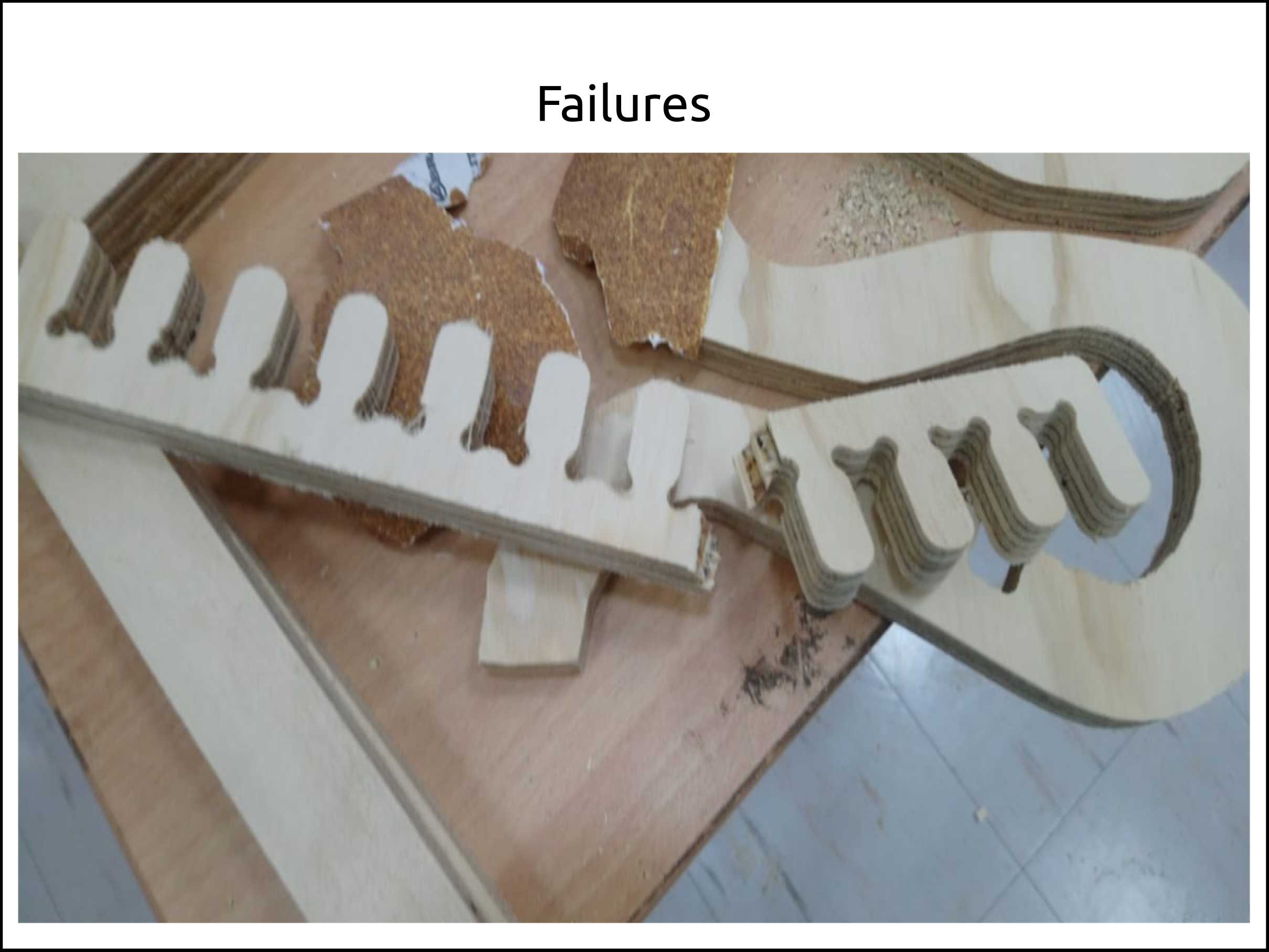
-
The slot has any clearance in order to fit with some force.
-
This is how it is supposed to look a separator with well fitting.
-
The separator has no tolerance as well.
Testing the chair
By testing the chair I figured out that the chair legs deform to its sides so tent to break. Because of that, I needed to add extra separators to it in order to reinforce the leg.

After I added the reinforcement to the chair leg I decided to make a destructive test to see what happens. So the chair works.
Obviously, it needs some modification but so far it was a great experience.

Faced problems and solutions ding the toolpaths
Problems:
-
The separator moved during the cutting process son caused a vibration of the piece so it reduced its strength and break after I release the part from the cutting table.
-
During the test, the chair bent to its sides.
Solutions:
-
I added more tabs to the model. So, as a general rule, it is better to add tabs to a long and thin piece.
-
The solution was to add more separators to its leg giving to it strength preventing the legs to bend to its sides.
Files of the ShopBot
What I learned this week?
I learned about the CNC_cookbook that has a software that improves your cutting time and the finishing of your product optimizing the speed rates and preserving the tool life.