14. Networking and communications
Group assignment:
Send a message between two projects Individual assignment:
design, build, and connect wired or wireless node(s) with network or bus addresses
Have you?
- Linked to the group assignment page
- Documented your project.
- Documented what you have learned from implementing networking and/or communication protocols
- Explained the programming process/es you used.
- Outlined problems and how you fixed them
- Included design files (or linked to where they are located if you are using a board you have designed and fabricated earlier) and original code.
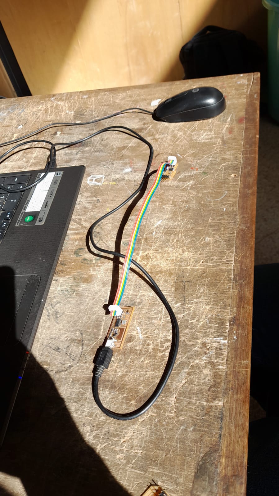
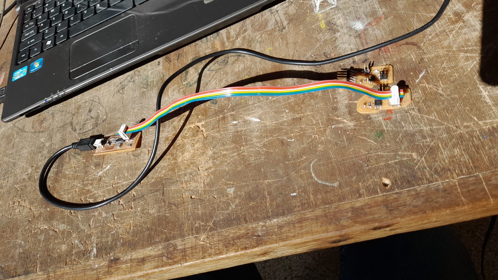
Bridge and node boards.
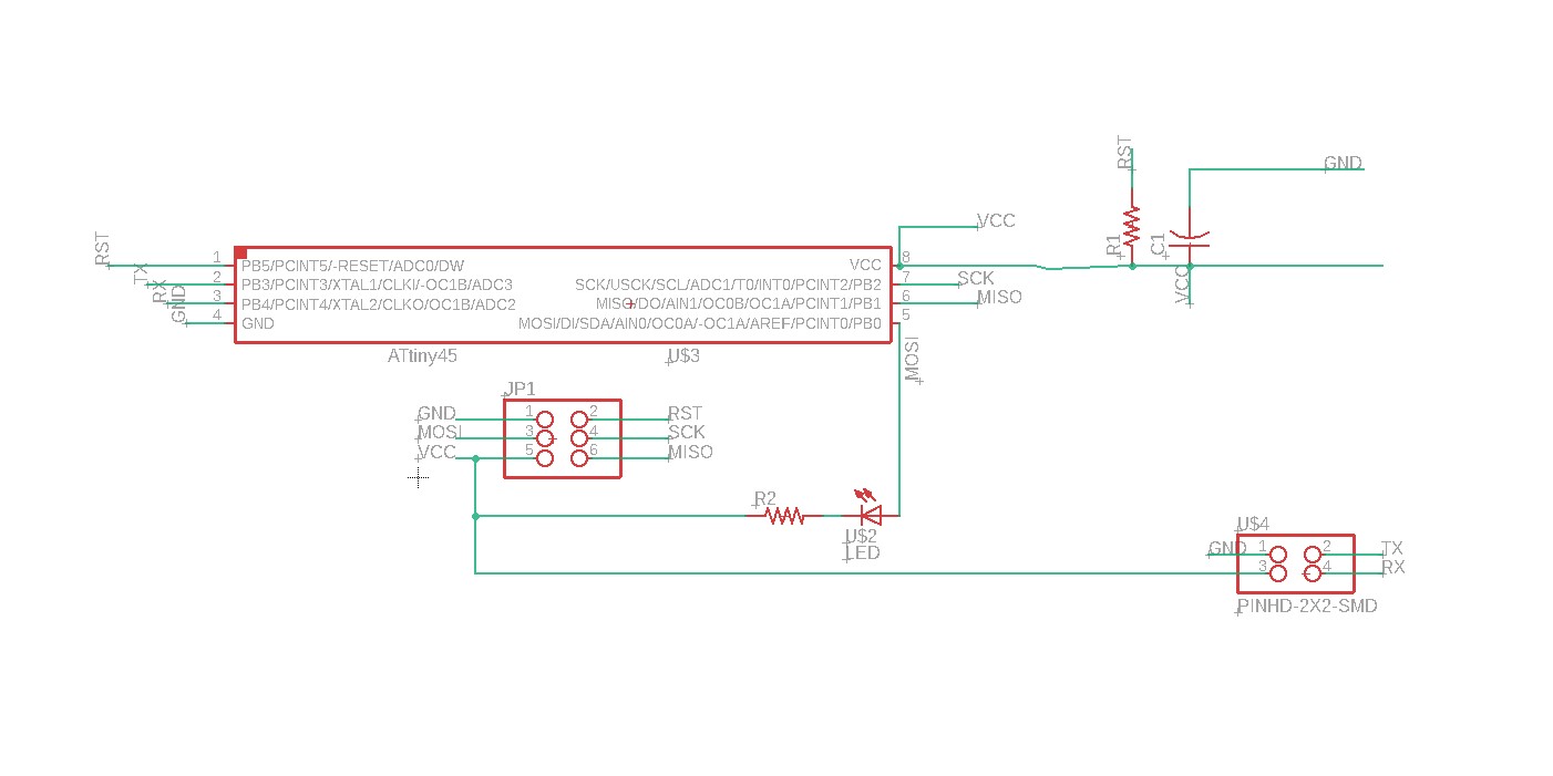
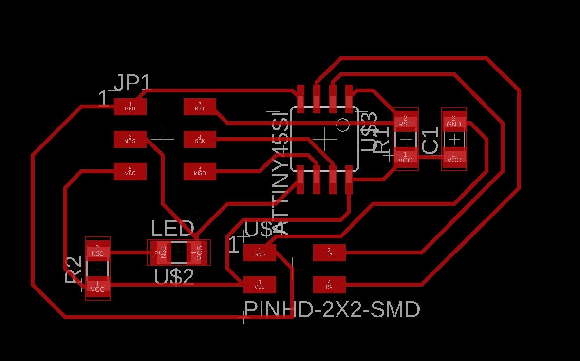
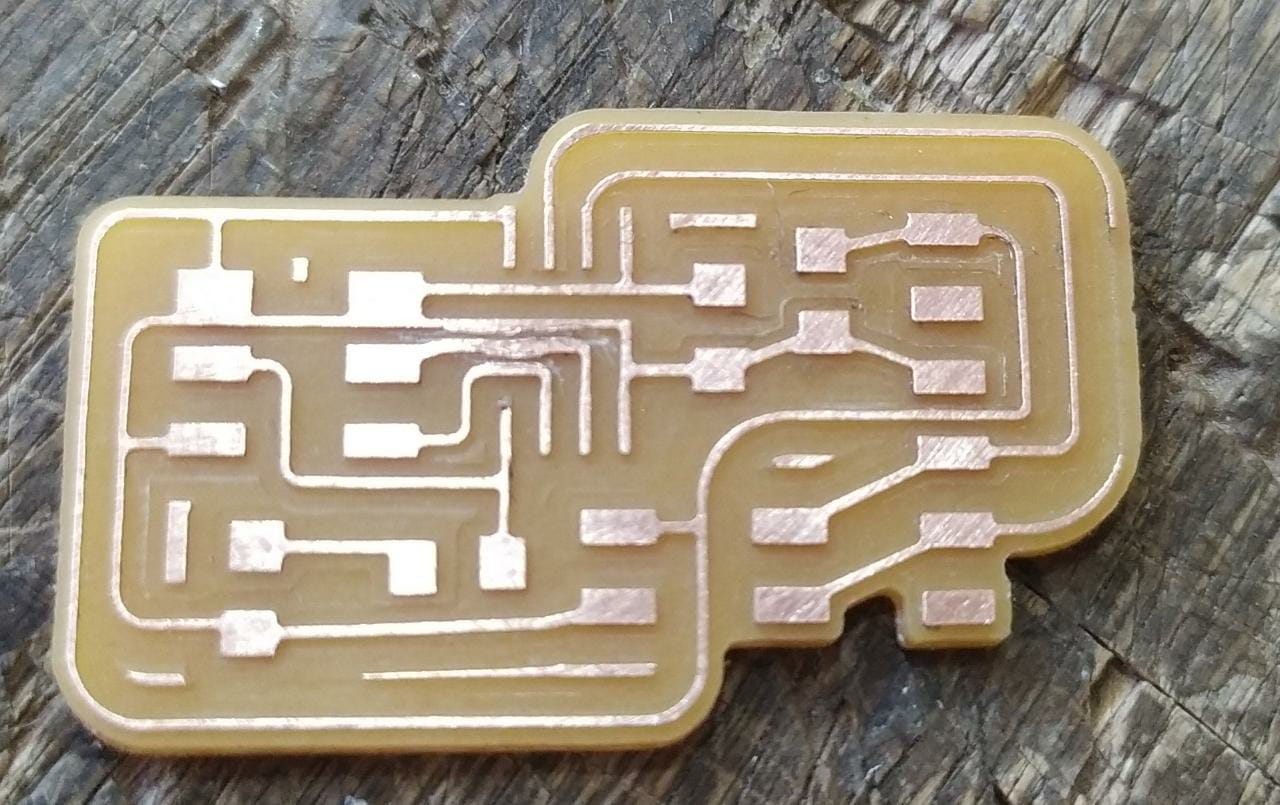
For this assignment I redrew the bridge and node boards from one of my instructors Silvia Lugo, and then I used a PCB milling machine I made to route the board. The board was made changing the circuit from class of Neil´s board, the main difference is the curves in the design, redrawn in the eagle software. This time since it changes almost nothing in the design I choose to use a very similar routing than Silvia´s.
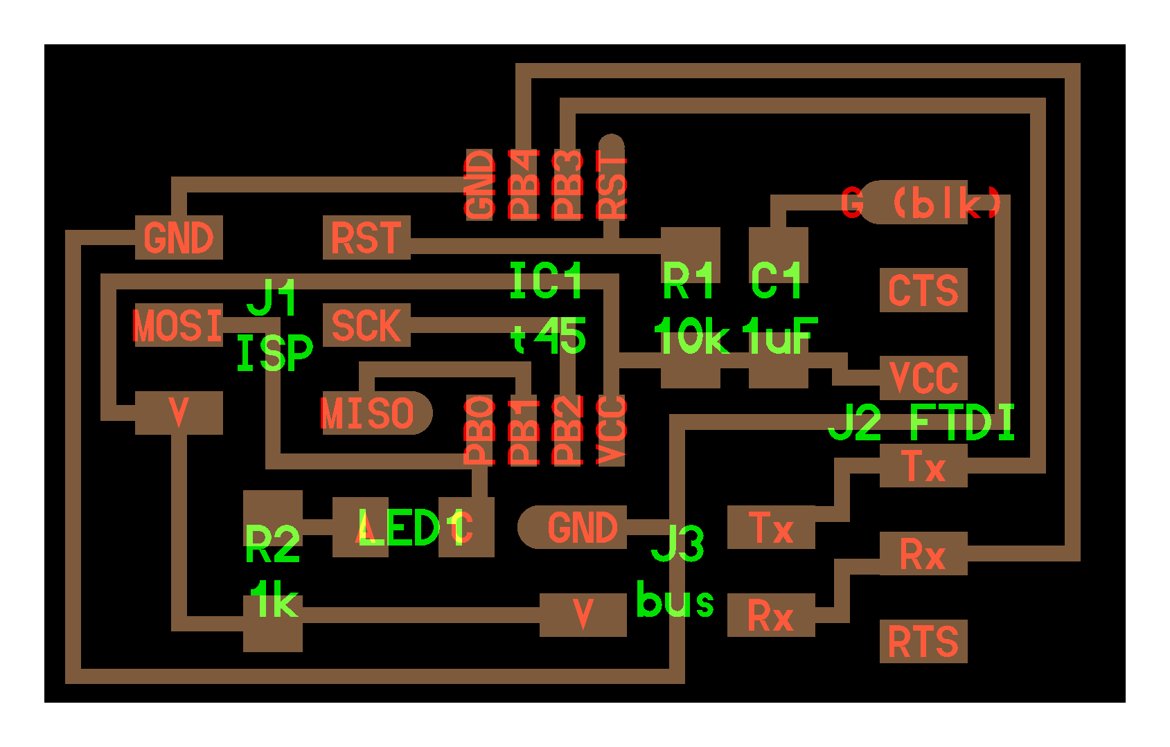
The bridge board
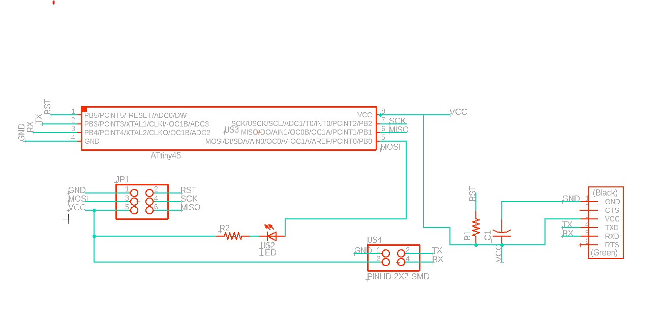
components
| Component | Quantity |
|---|---|
| Attiny45 | 1 |
| 10k Resistor | 1 |
| 1k resistor | 1 |
| 2x2 pin header male | 1 |
| 1uf capacitor | 1 |
| 2x3 pin header | 1 |
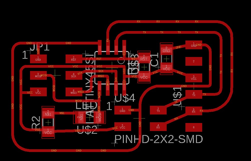
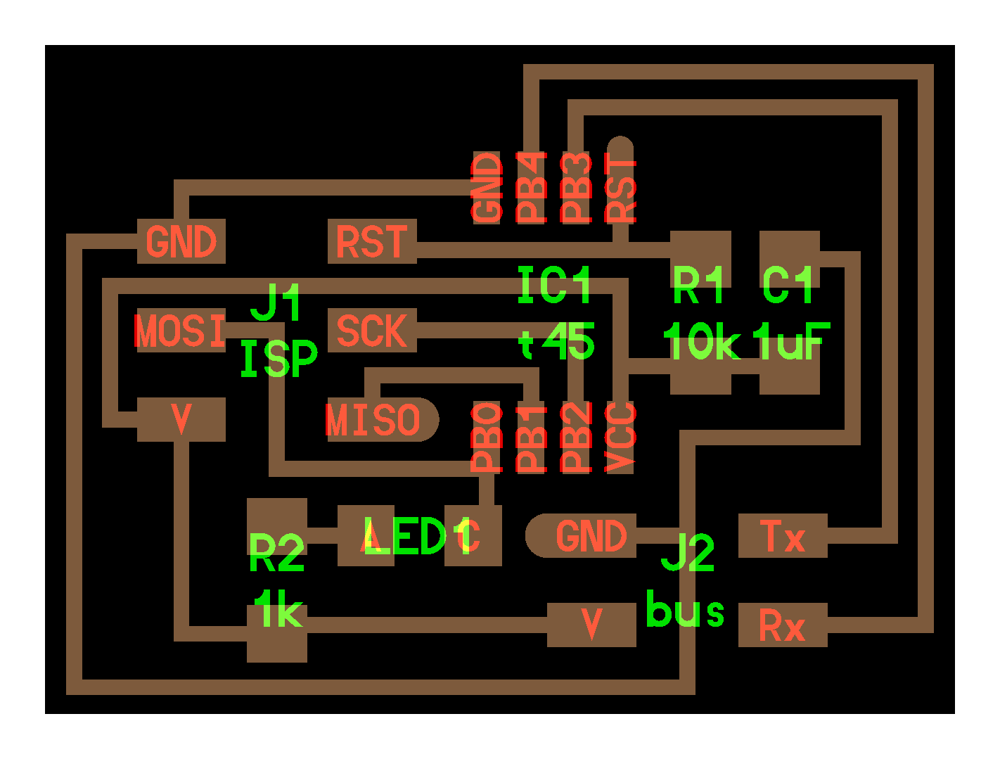
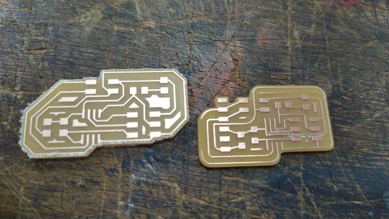
The Node board
In the node board I made all the routing from scratch, you can see the difference comparing both circuits.
| Component | Quantity |
|---|---|
| Attiny45 | 1 |
| 10k Resistor | 1 |
| 1k resistor | 1 |
| 2x2 pin header male | 1 |
| 1uf capacitor | 1 |
| 2x3 pin header | 1 |
Exporting the gerber file and setting up flatcam
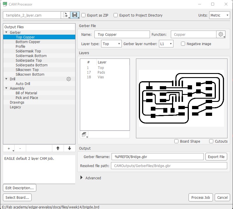
At eagle I used the cam processor to export the gerber files, at the top copper for the smd board.
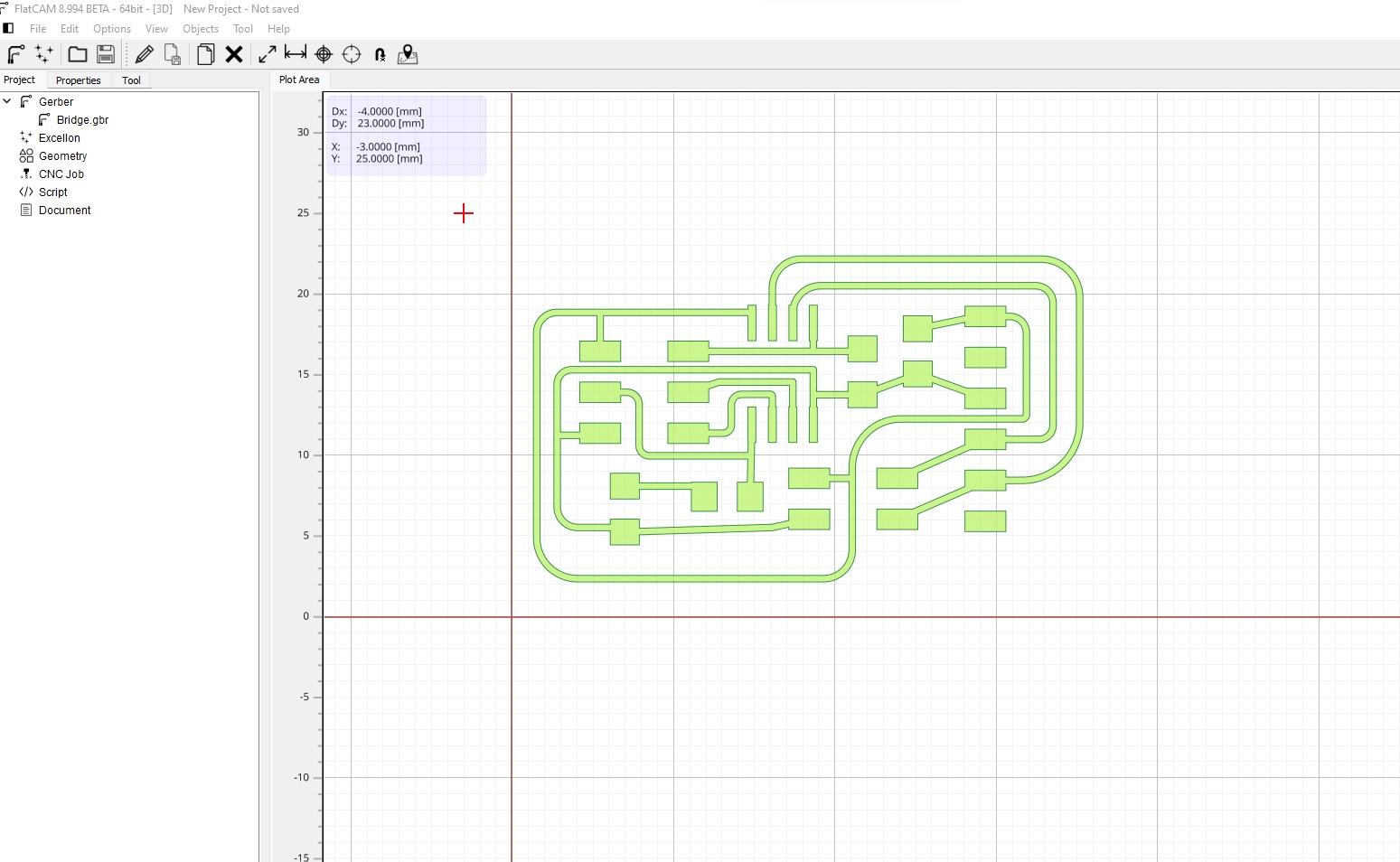
The first thing to do is to move the position of the board and put it at the positive quadrant of the cartesian axis.
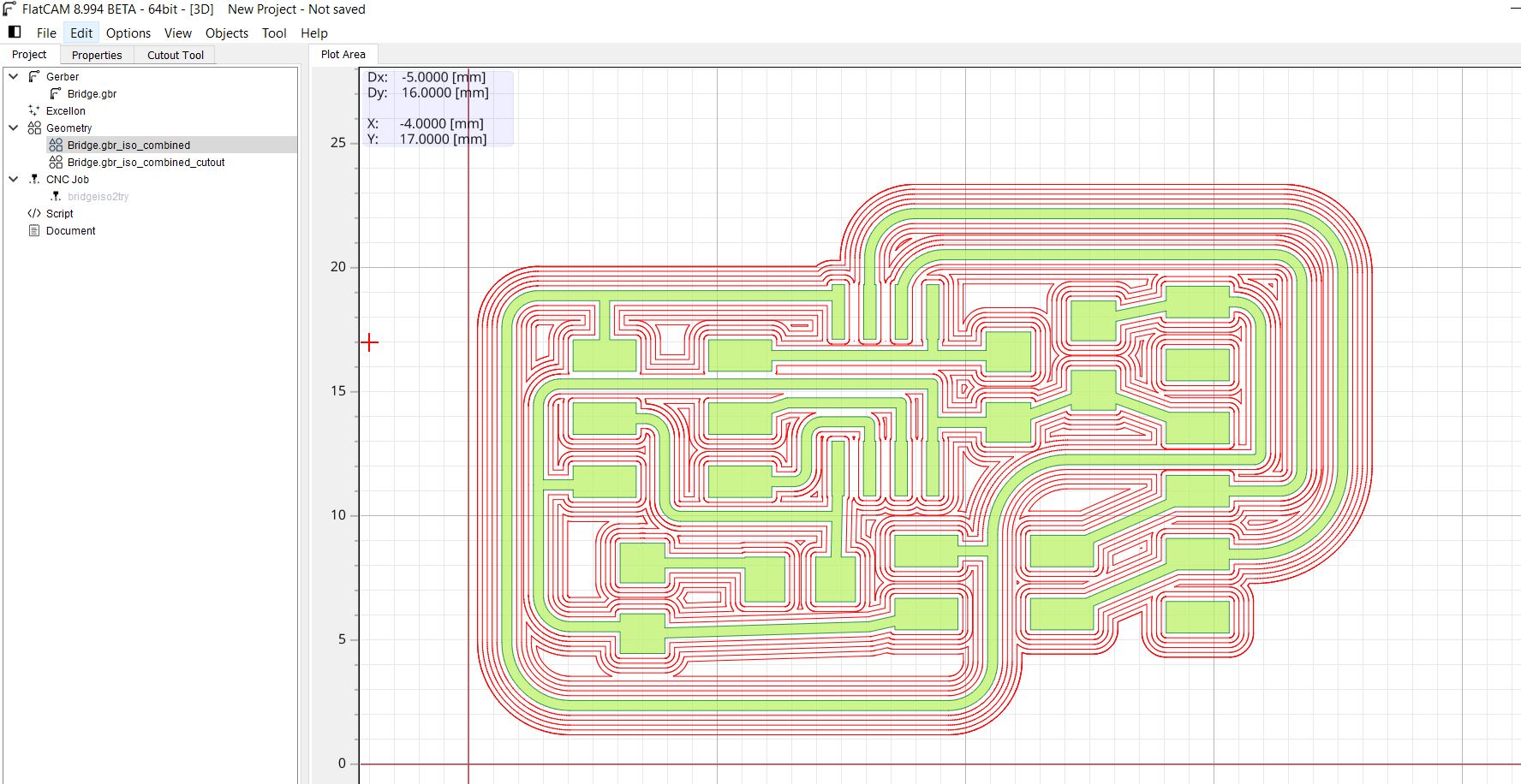
the second step is the isolation routing for the board, I used 5 passes with 50% overlap with a 1/64 inch bit.
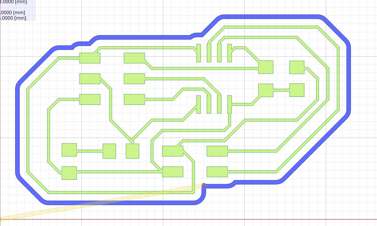
And finally the cutout with a 1/32 bit.
Machining the boards
Sometimes I needed to make some PCBs at home when I did not have time to go to the fab lab so I built a small 3018 like for cnc milling. It is much smaller than the rolland and less powerfull but I think I got some ok results with it.
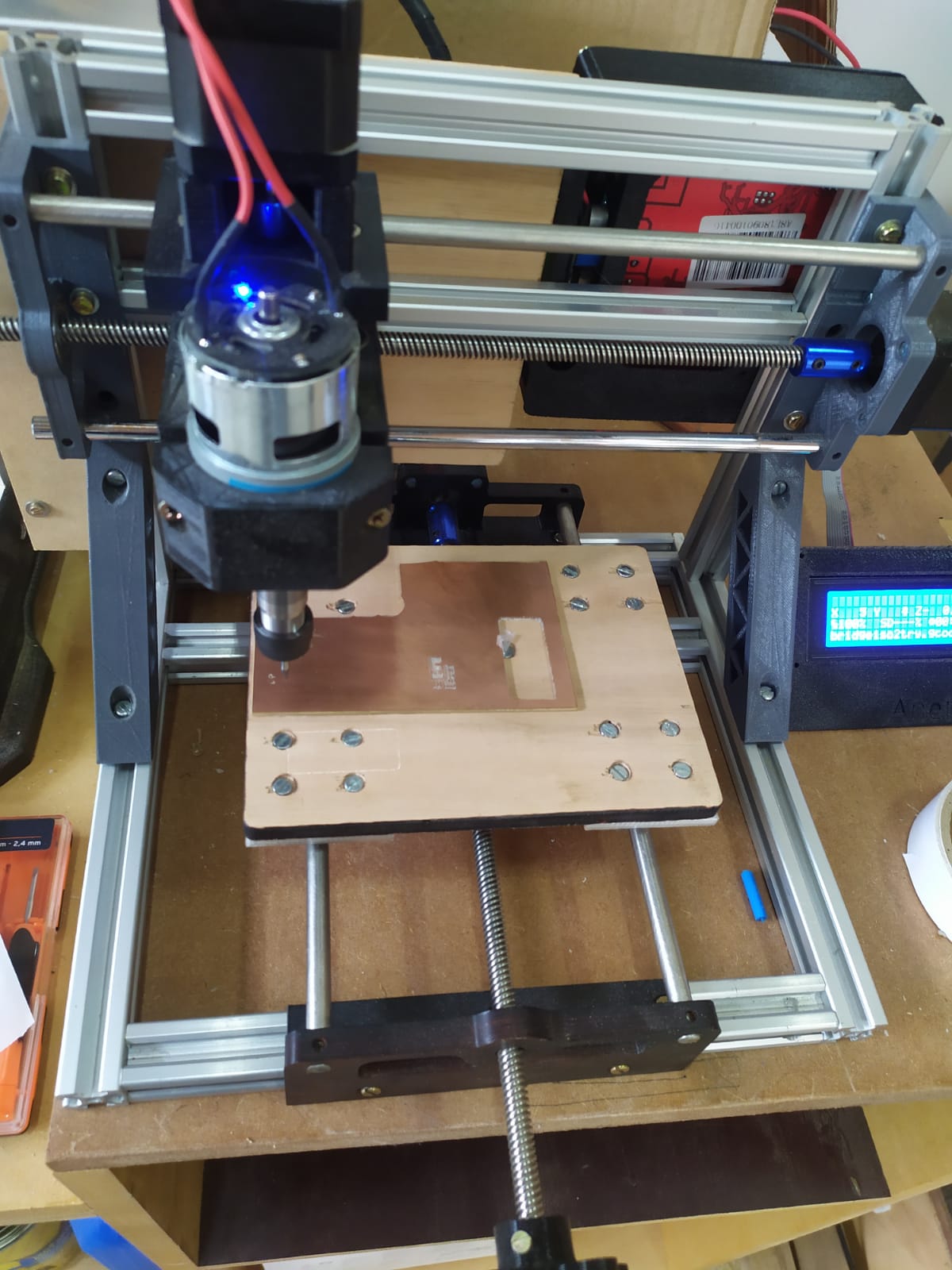
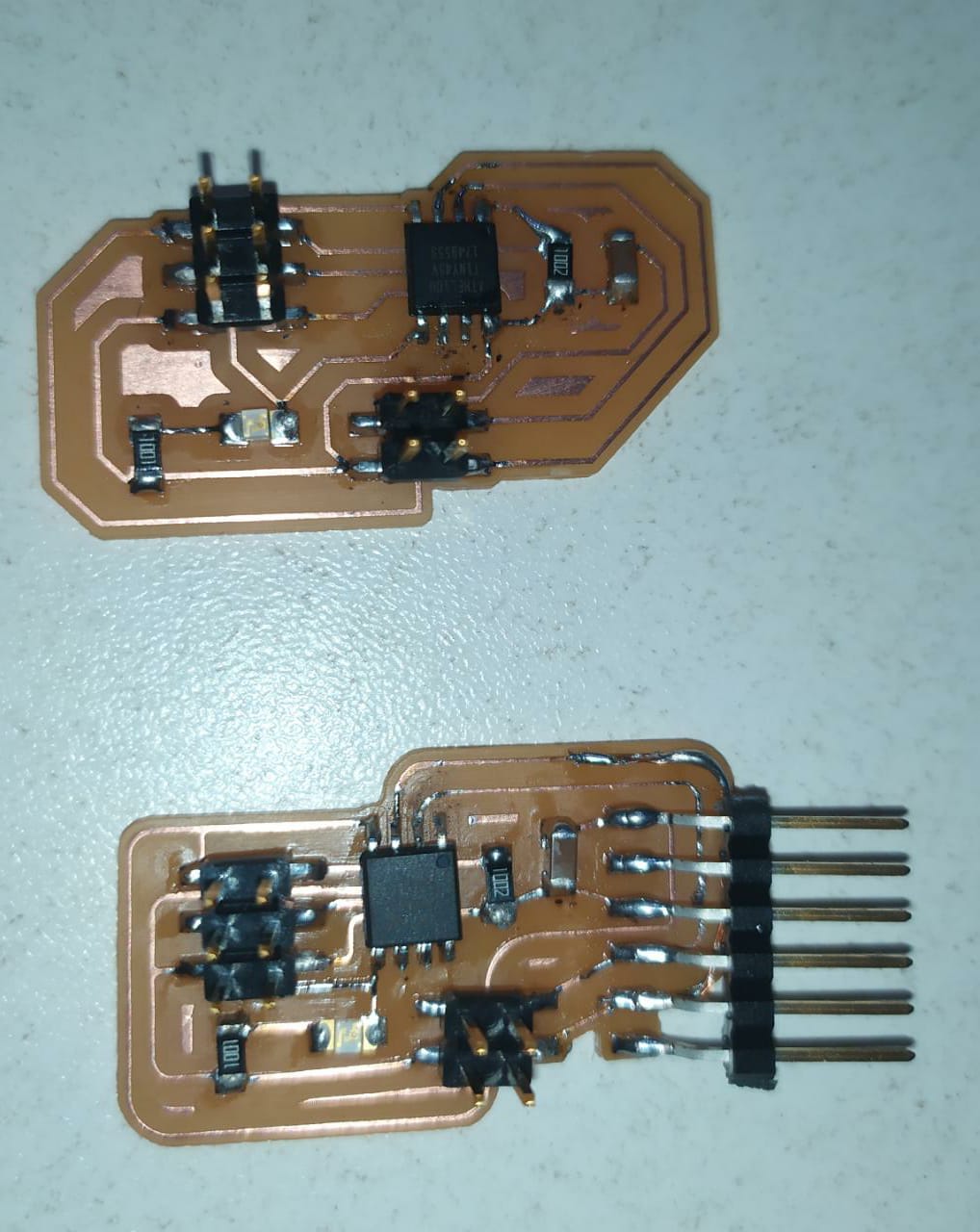
I used a 1/64 inch bit for the main traces, and a 1/32 inch bit for the cutout.
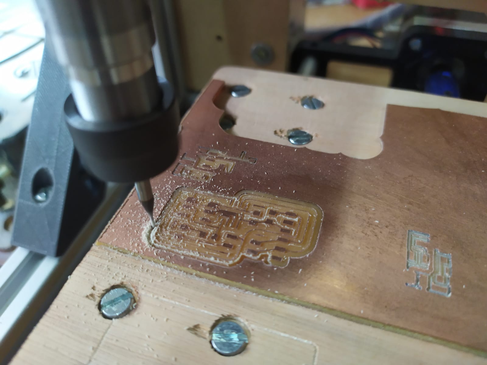
I had to use a cutter to separate a few traces because the bit didn´t pass all the way throug, and also I added a small copper wire in the right trace.
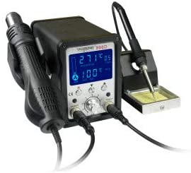
Soldering
For soldering I use a Griffing Soldering station similar to the one in the picture.
One of the problems I had is that the tip of the solder was broken so no proper heat transfering.
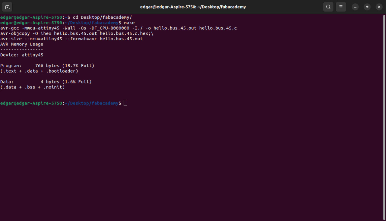
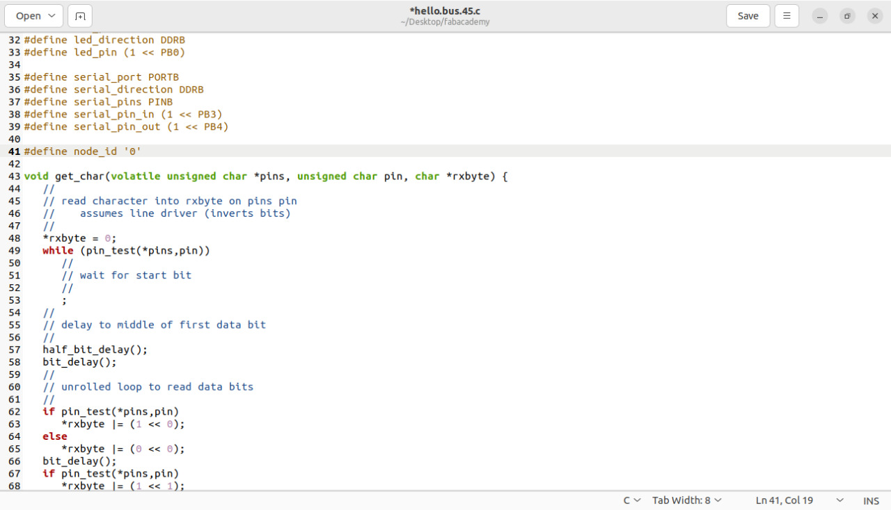
Programming
To start programming I used the examples from the class
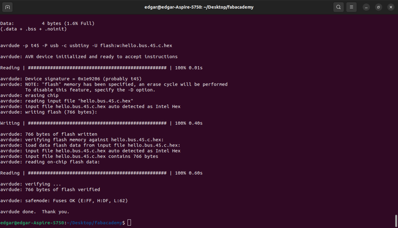
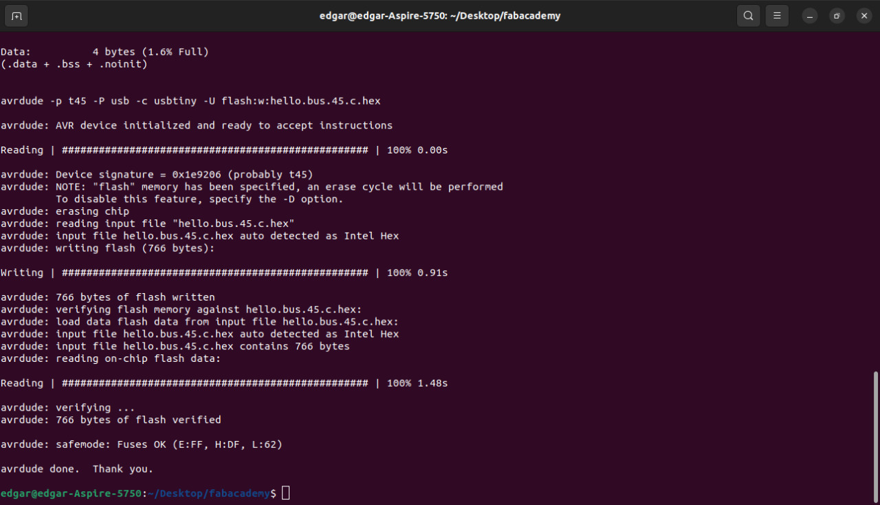
To program the files, I used Ubuntu linux and my USBTiny that I made in week 5 and made the following commands.
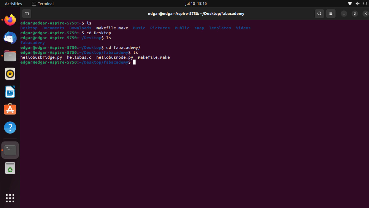
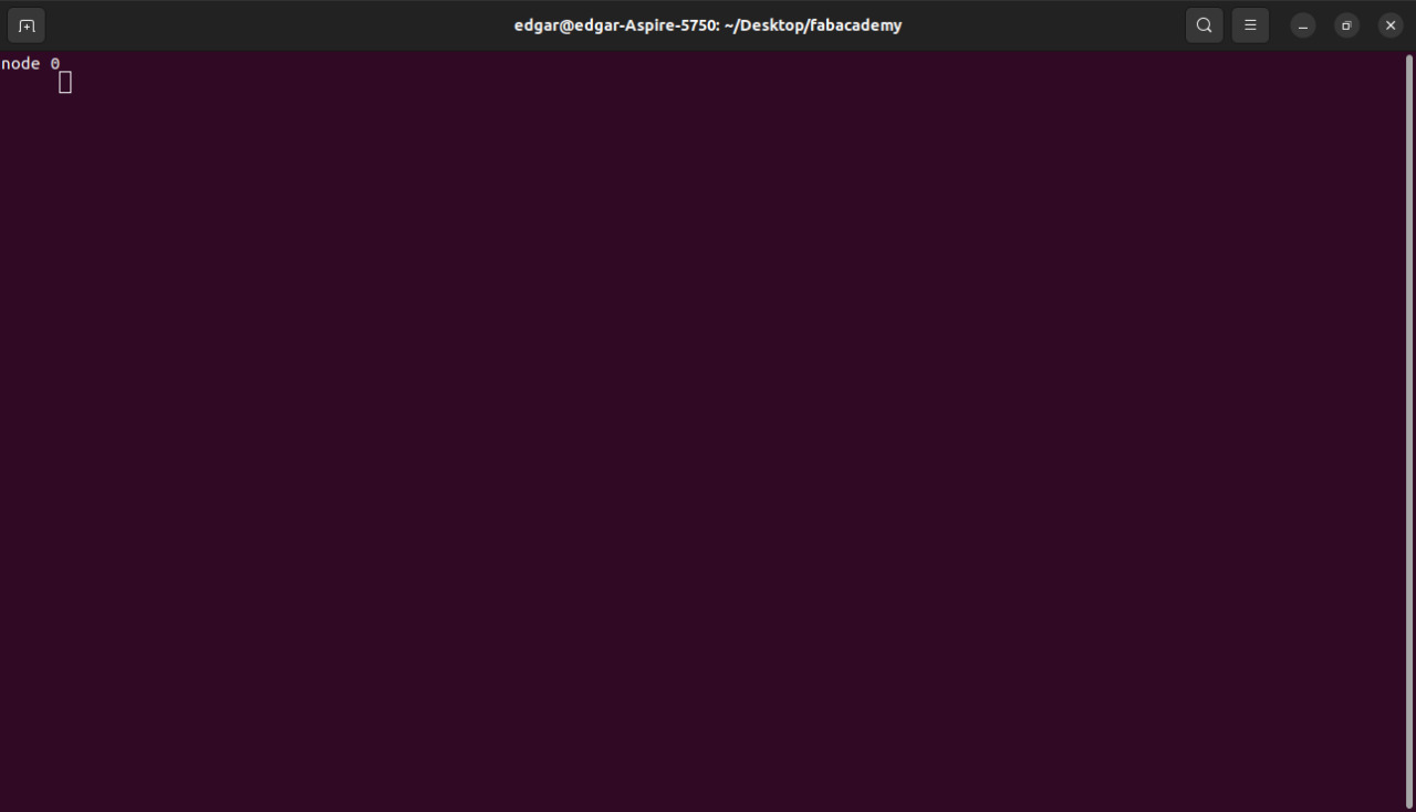
steps to load the program
- use the cd command to enter the directory of the files to the programming directory.
cd desktop/fabacademy