13. Input Devices
Input devices Assessment
Group assignment - Probe an input device(s)’s analog and digital signals - Document your work (in a group or individually)
Individual assignment - Measure something: add a sensor to a microcontroller board that you have designed and read it.
Have you?
- Linked to the group assignment page
- Documented what you learned from interfacing an input device(s) to microcontroller and how the physical property relates to the measured results
- Documented your design and fabrication process or linked to previous examples.
- Explained the programming process/es you used
- Explained problems and how you fixed them
- Included original design files and source code
- Included a ‘hero shot/video’ of your board
Group Assignment
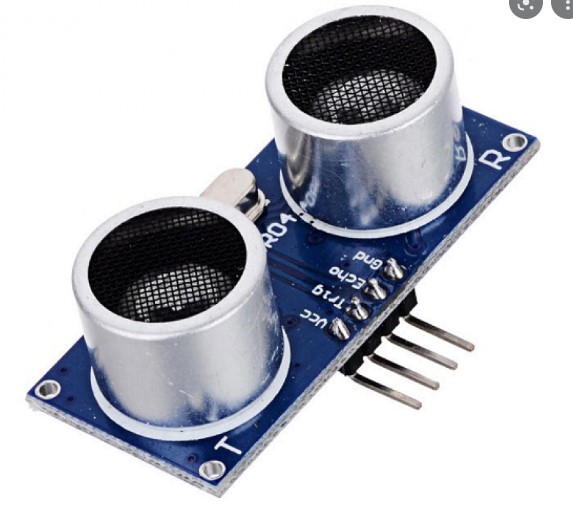
Ultrasonic Sensor as an Input device
This type of sensors works by emitting an ultrasonic wave, and then receiving it back again reflectedc from a target object, using a microcontroller we can calculate the distance with this parameters measuring the time between the sound emission and receptcion.
The distance calculated by a microcontroller using an ultrasonic sensor follows this formula:
L = 1/2 * T * C
the letters from the variables means the following:
-
L is the distance between the target and the transmitter.
-
T is the time between the emission and reception.
-
C is the speed of the sound (sonic speed).
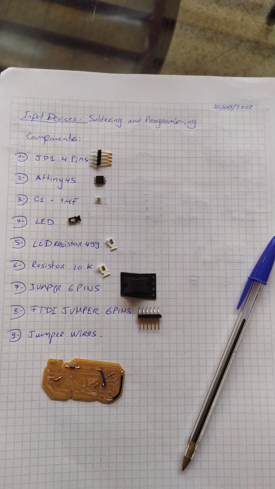
This sensor has 4 pins wich are:
-
Vcc:
-
Trigger:
-
Echo:
-
GND:
Microcontroller
For the purpose of this week, I choose the Attiny44
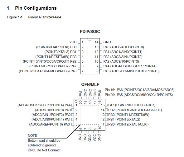
As you can see from the datasheet this microcontroller has enough inputs pins to control an ultrasonic Sensor. This is one of the most used ICs from CIDI Lab so I choose this one.
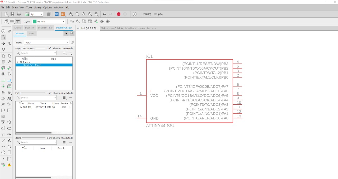
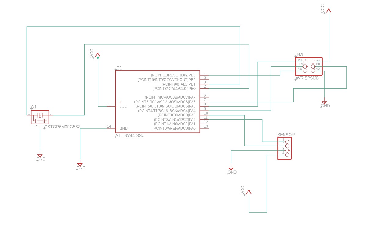
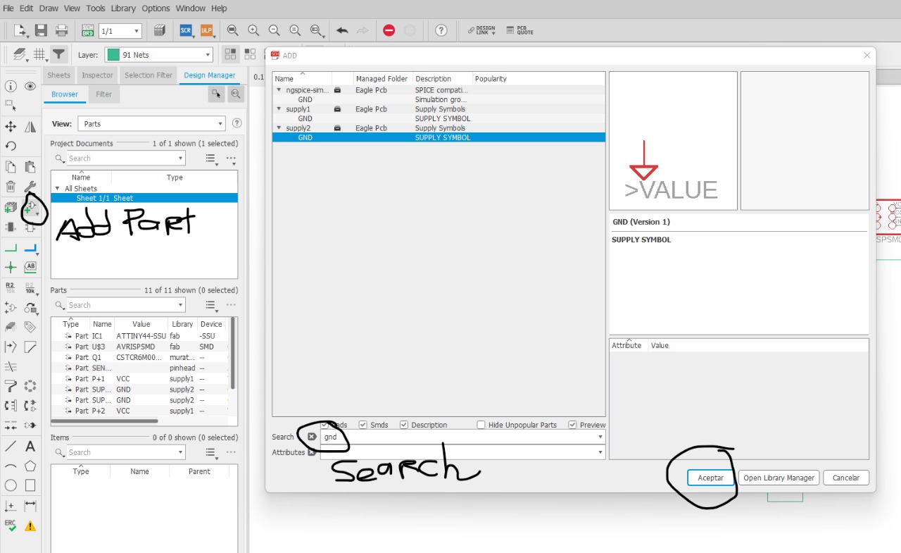
Eagle
This time I downloaded the Eagle library from the fab academy page:
Making everything over again
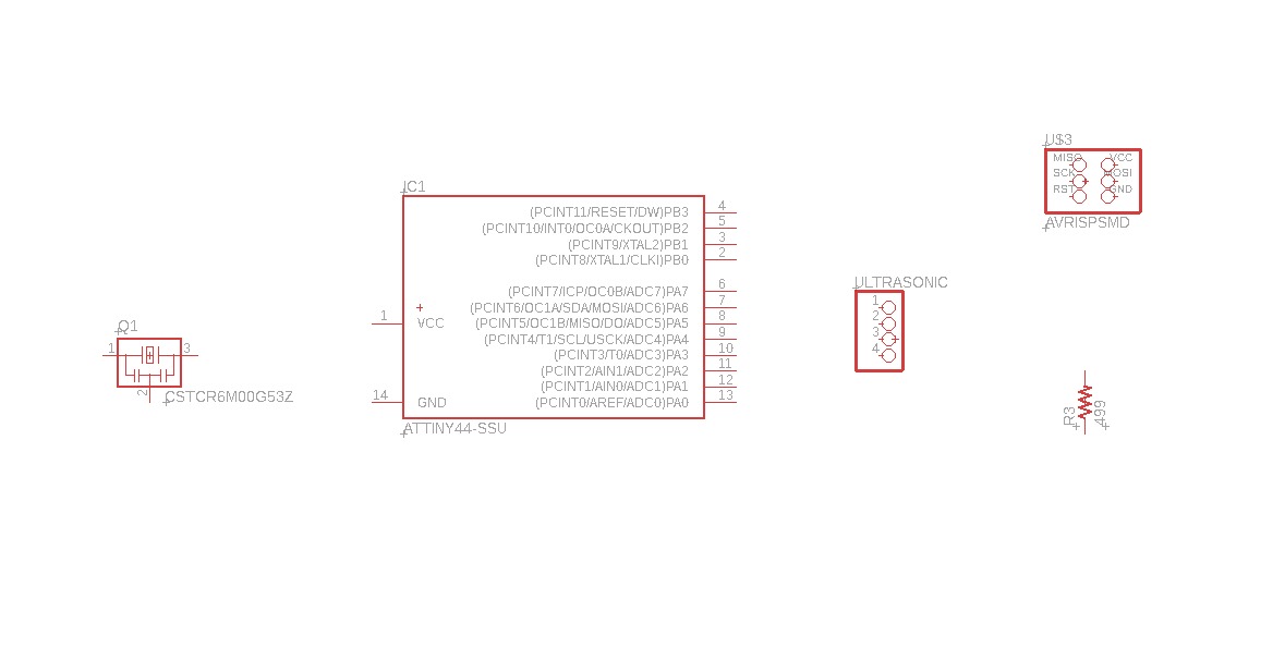
Schematic and design
As for the output board, I started by making an schematic in paper on my notebook, I based my design from Fabio Ibarra´s page, I added a Power Led and Resistor and modified the tracks with some cables for easier machining.
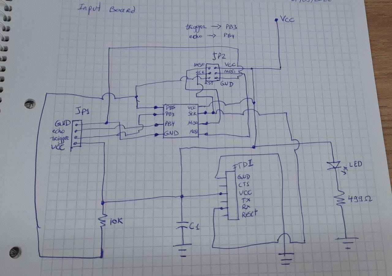
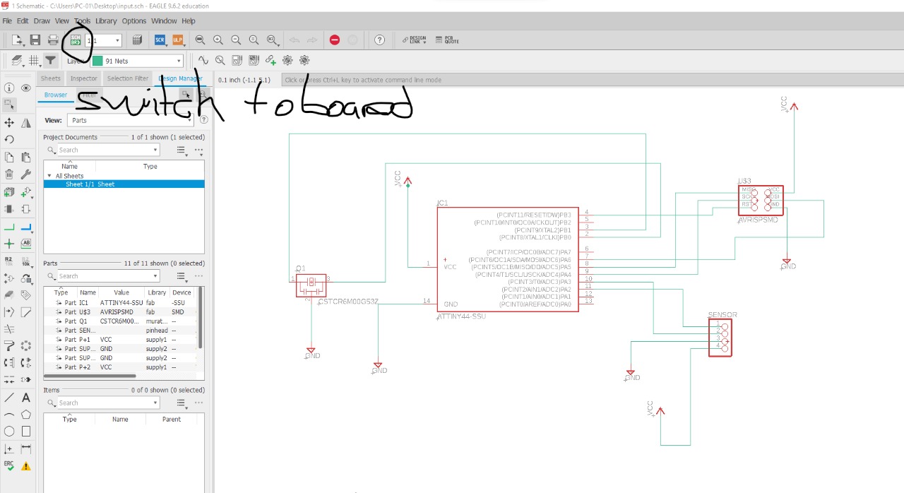
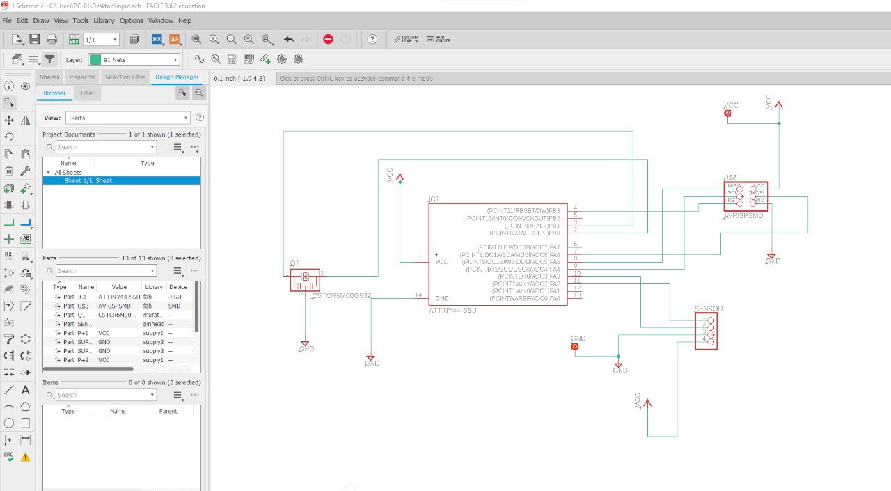
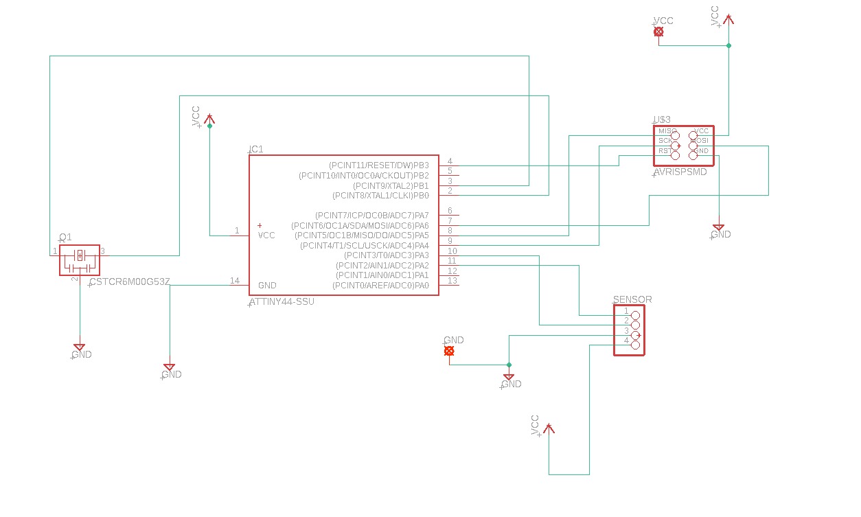
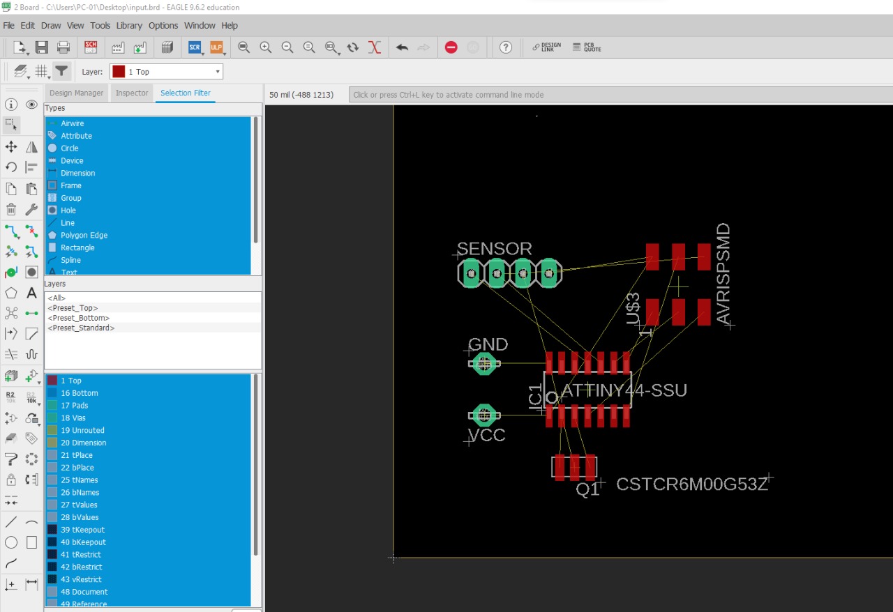
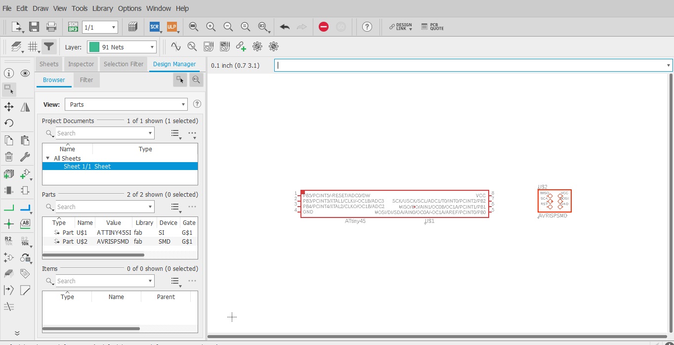
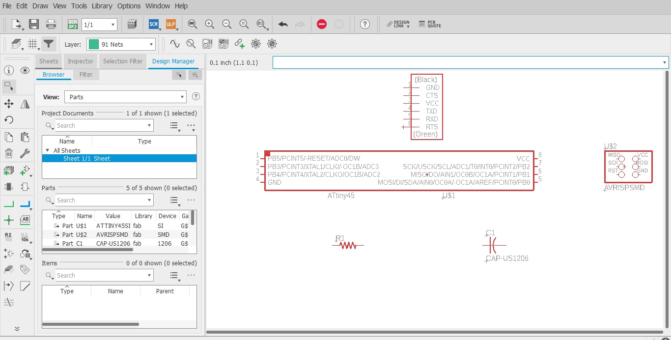
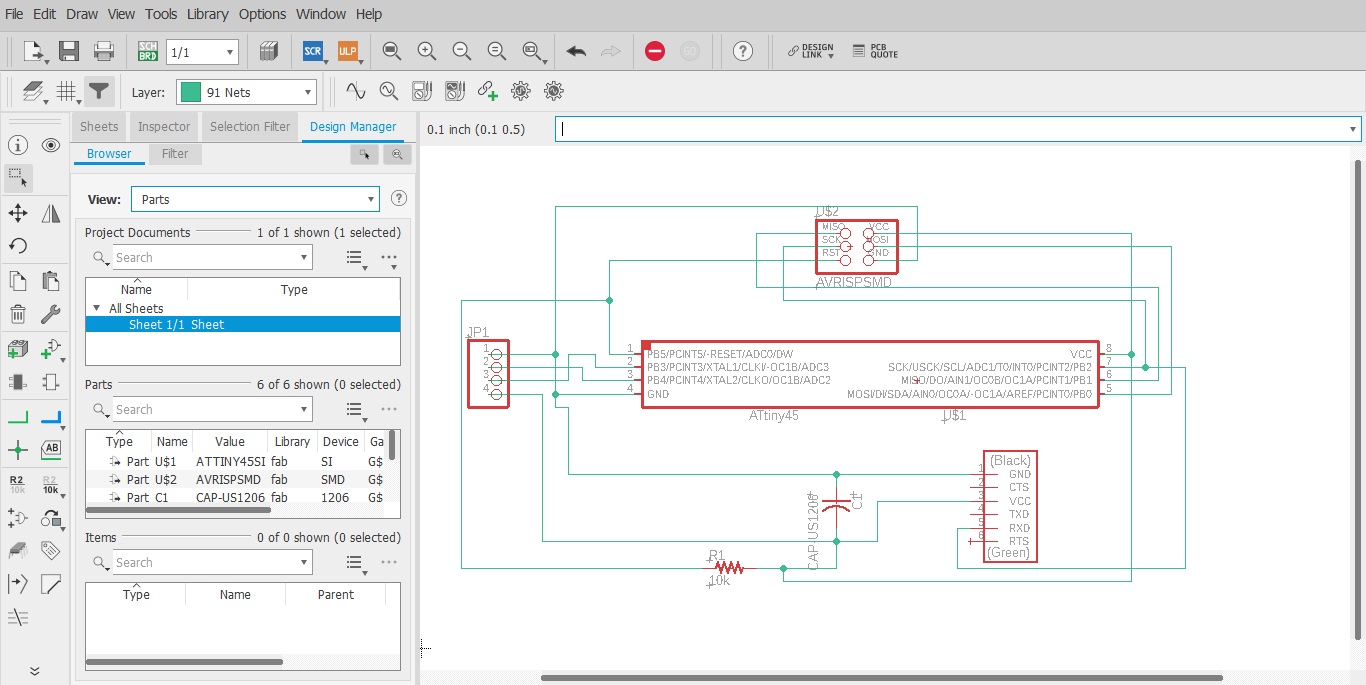
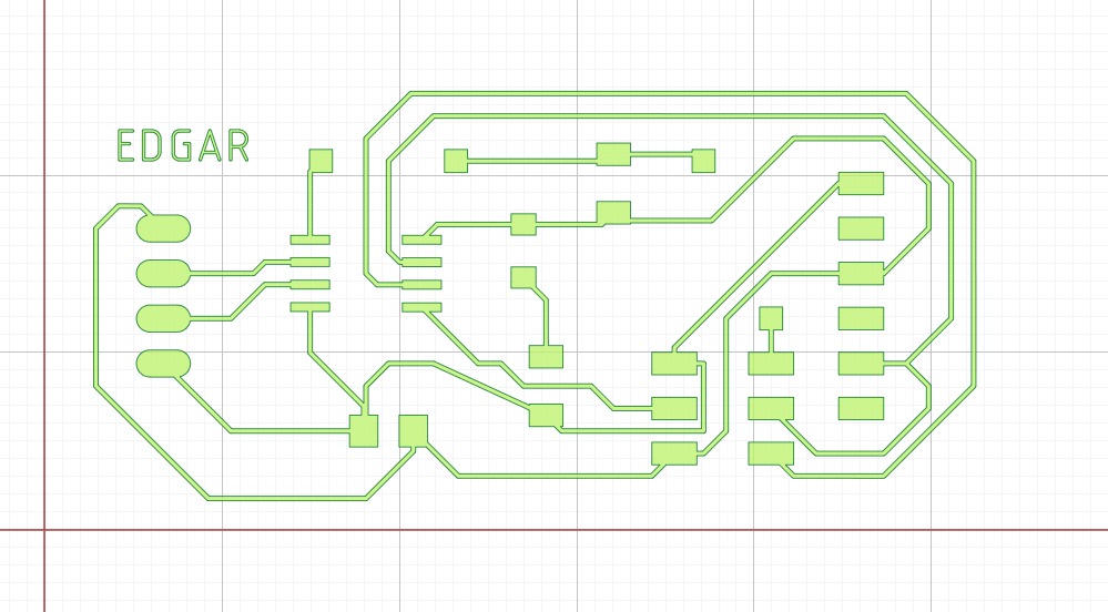
Created the schematic in eagle and then proceeded to create the routing for the PCB.
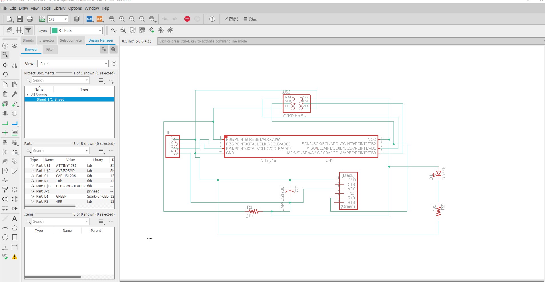
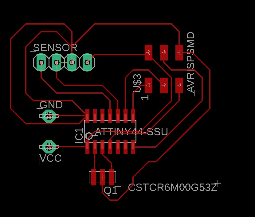
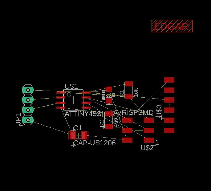
Added my Name to the board using the Letter tool in Eagle Board section. Then ordered all the components to be properly spreaded and not all.
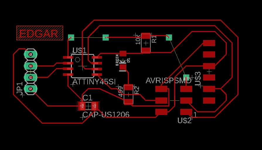
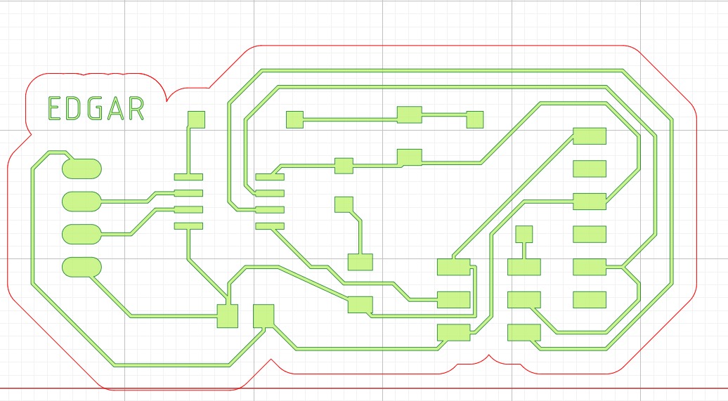
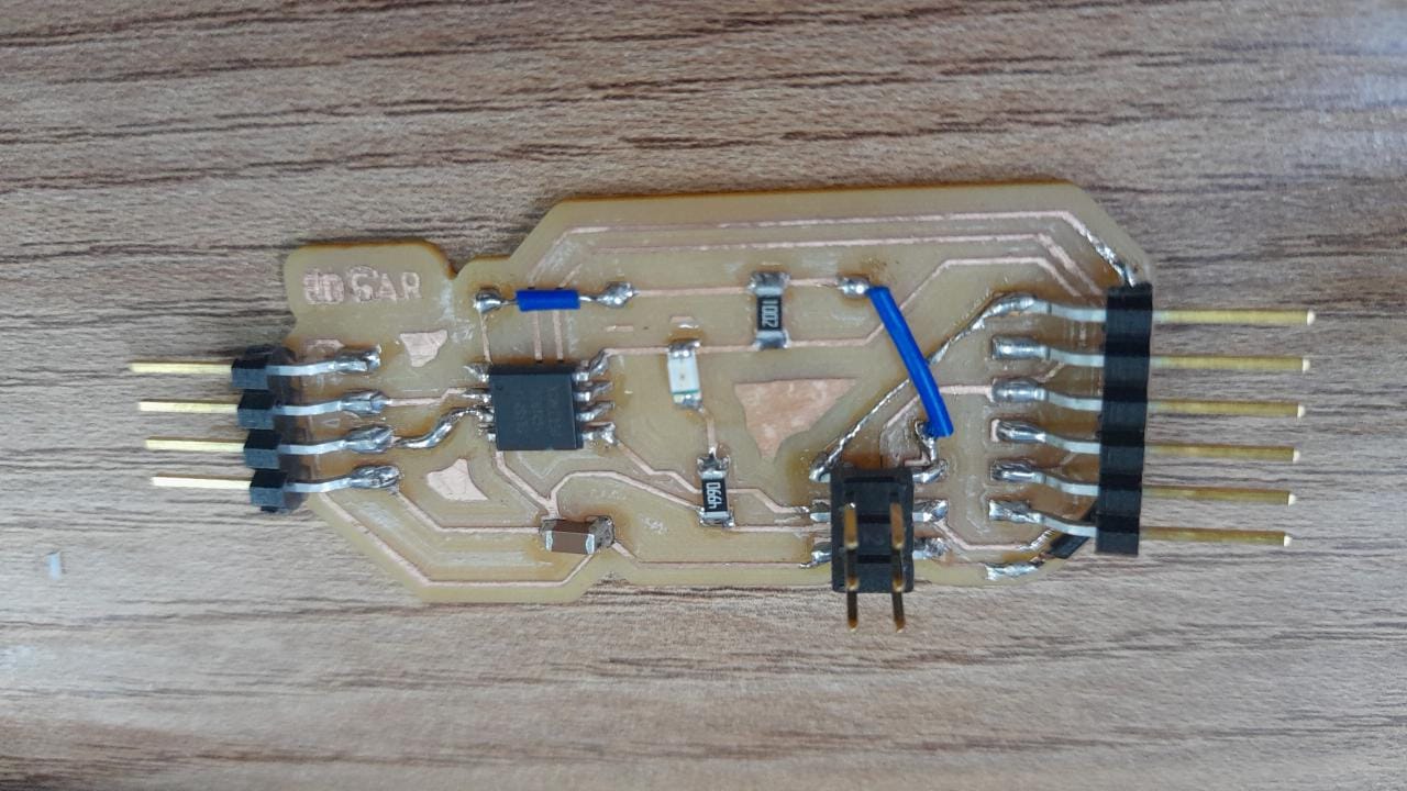
After deciding the routes for like 30 minutes, I decided it would be good with 2 bridge wires like shown in the picture.
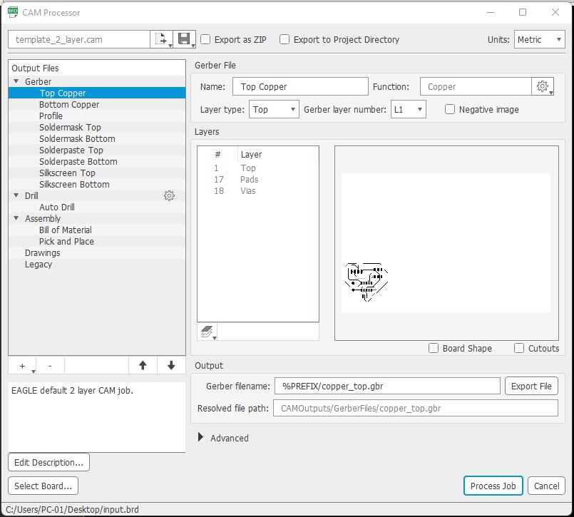
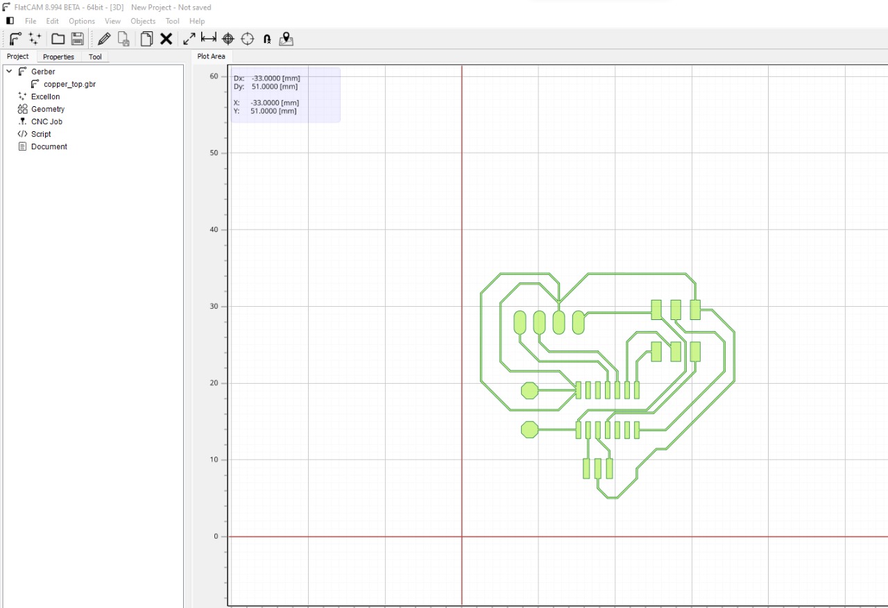
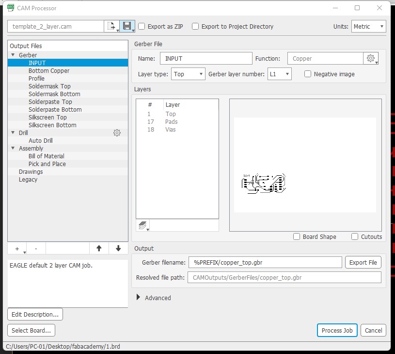
Later I used the cam processor to Export it and opened the gerber file in flatcam.
Flatcam and Routing
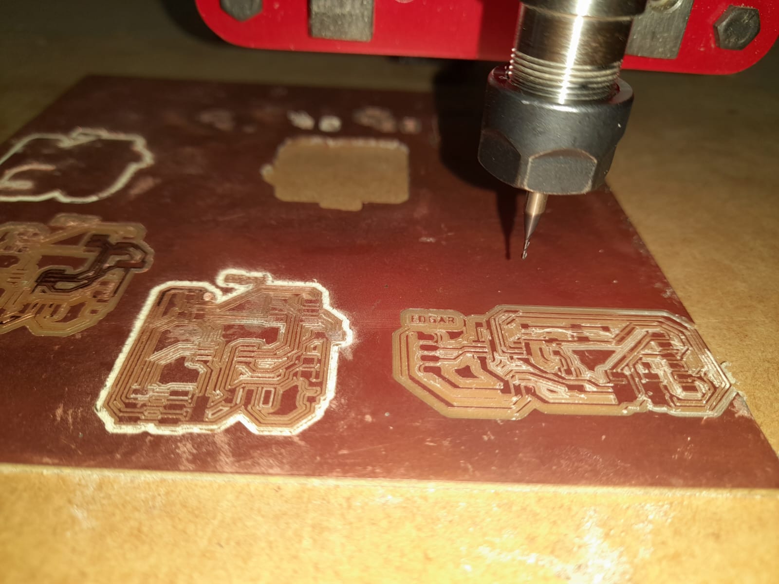
I opened the project in flatcam, used a 1/64 inches router bit for the traces and then a 1/32 inches bit for the cutout.
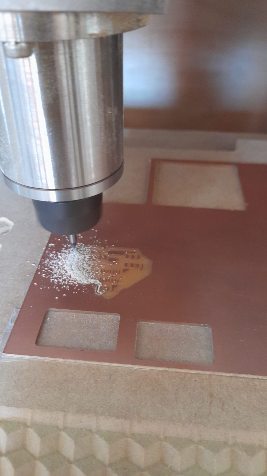
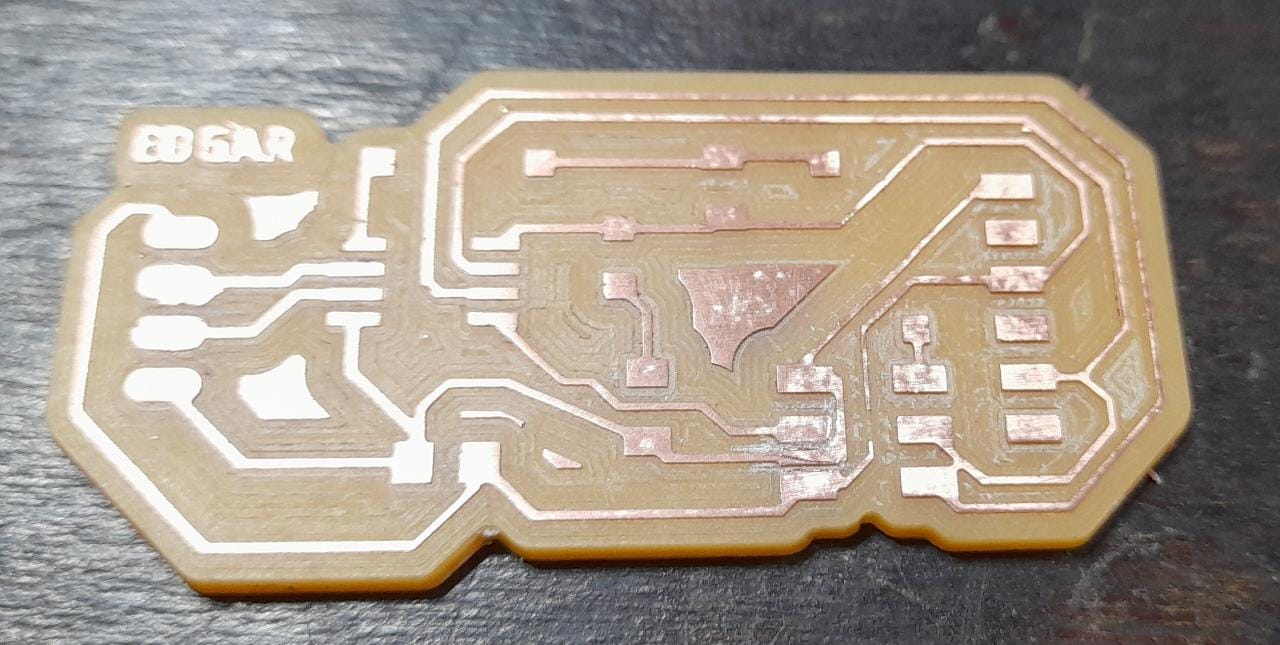
I used my final project again to machine this PCBs, this time I had more practice with it and the result came out beautifuly.
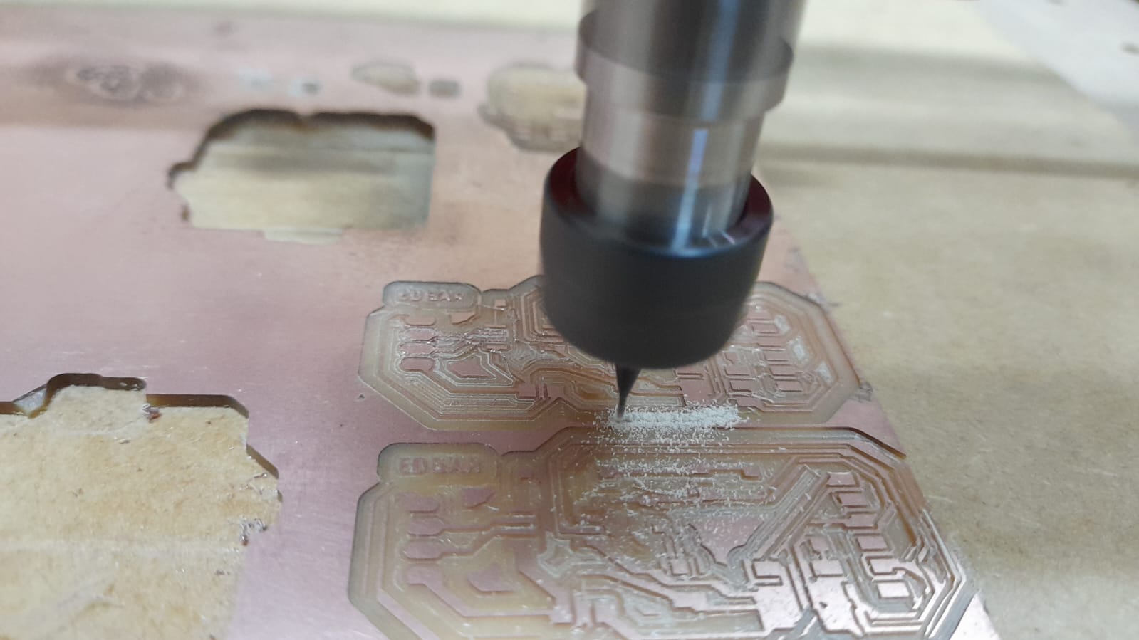
but on the second try, because one of the coupling screws in the X axis got loose, and the first board I machined didn´t come out so well as you can see in the picture.
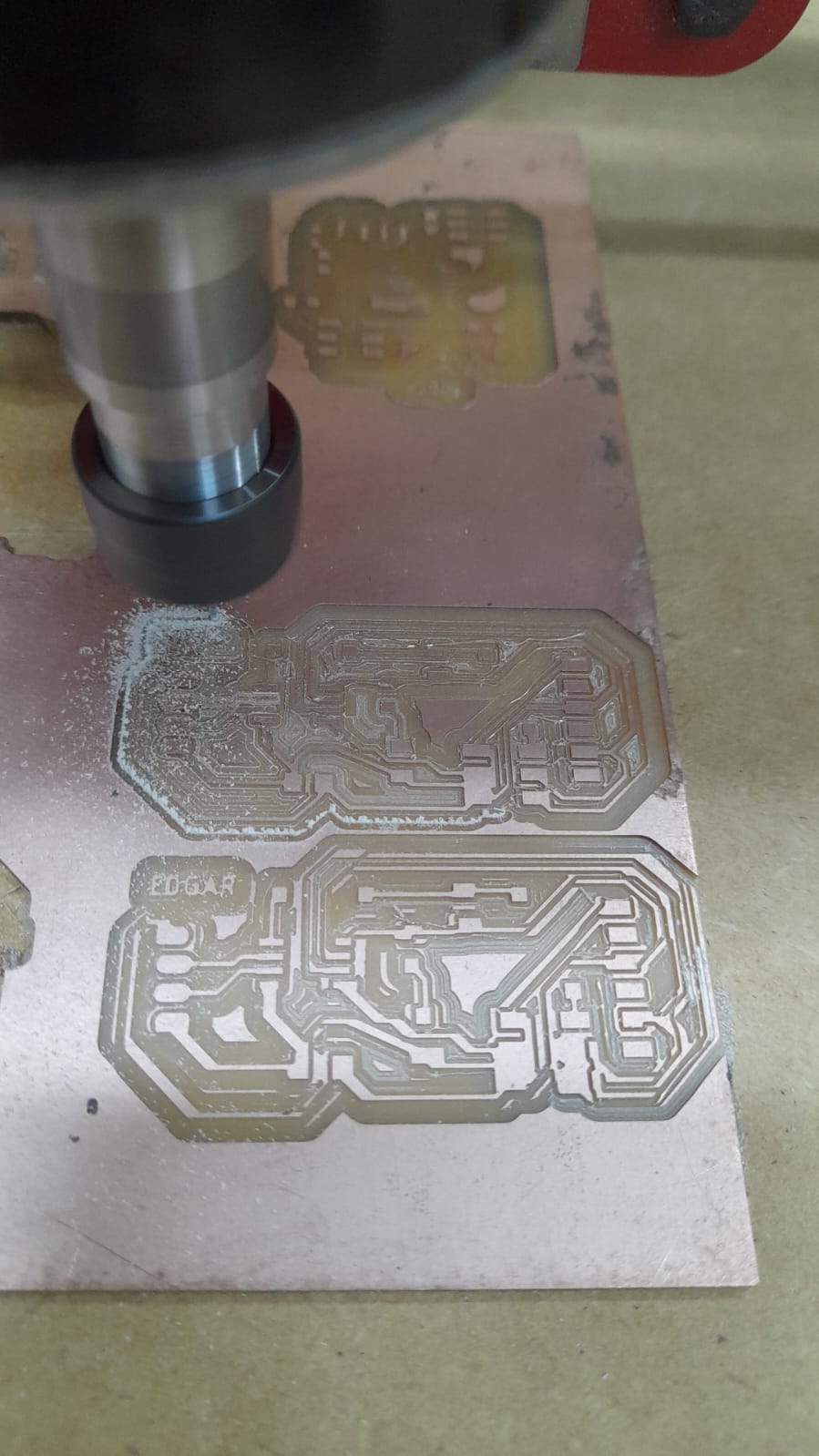
I think the most valuable lesson I have learned in the fab academy is to consider things can go wrong all the time and I have to be prepared for it, this time I had a perfectly good board made, and perfectly forgotten it at home.
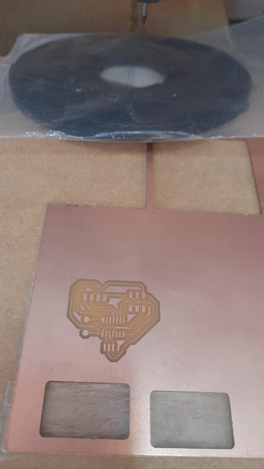
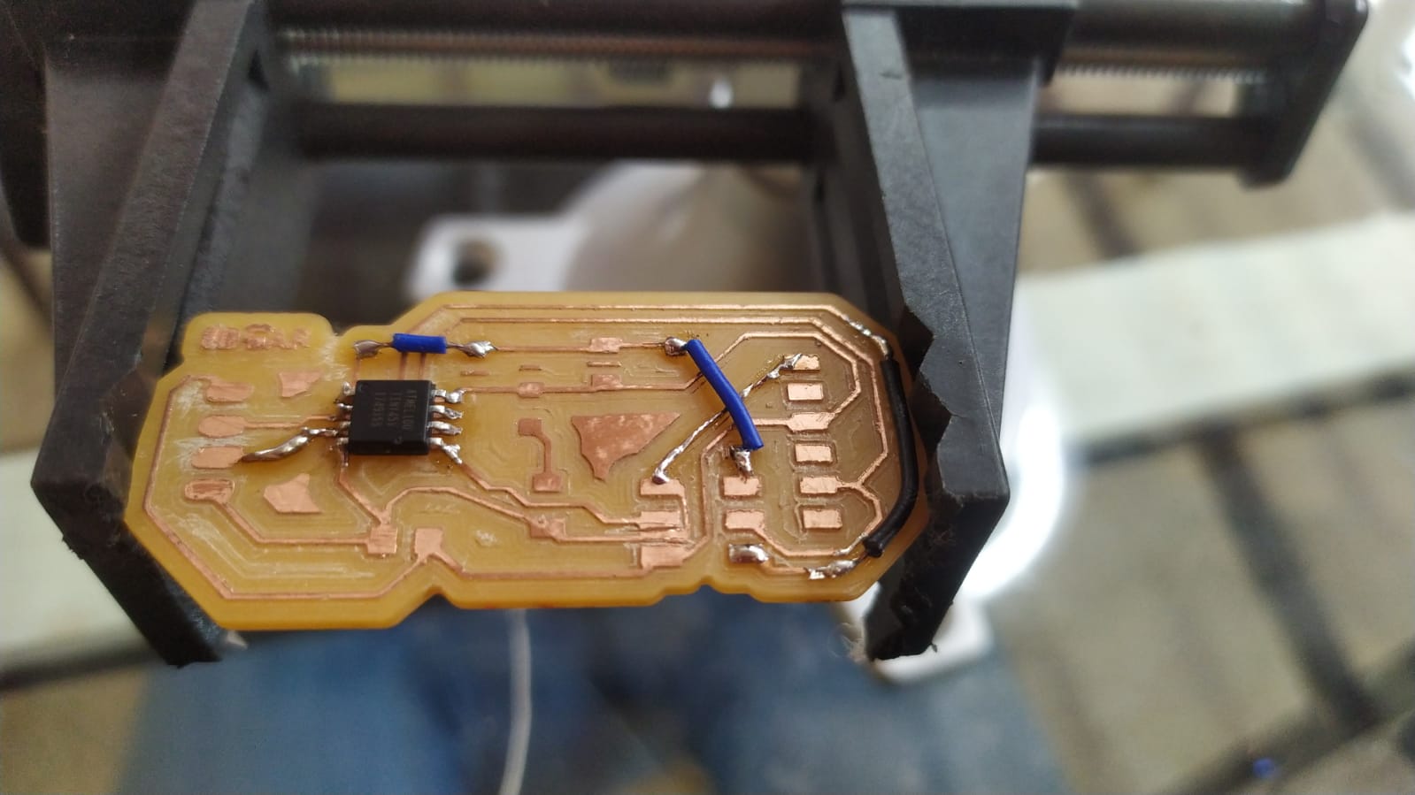
This time I didn´t even feel bad for it, and started right away making a new one, the machine did all the work and had a brand new board in 30 minutes. this time it didn´t came out so good but nothing a good pair of wires coudn´t fix.
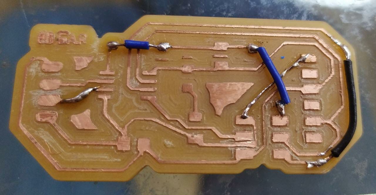
The blue wires are the intentional jumper wires, and the others are the events of fortune jumper wires.
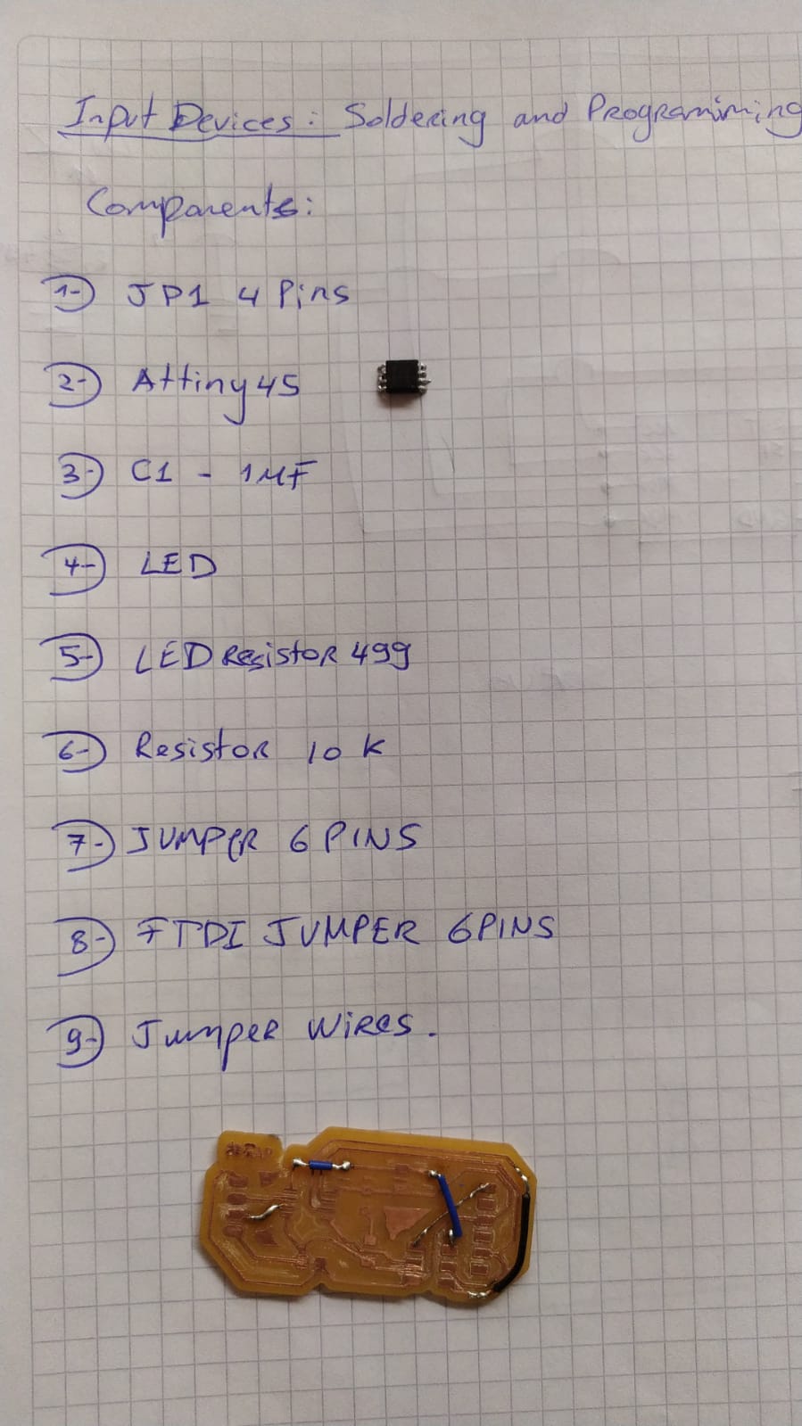
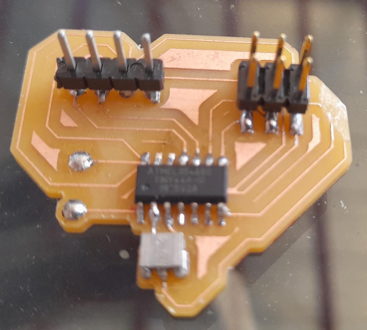
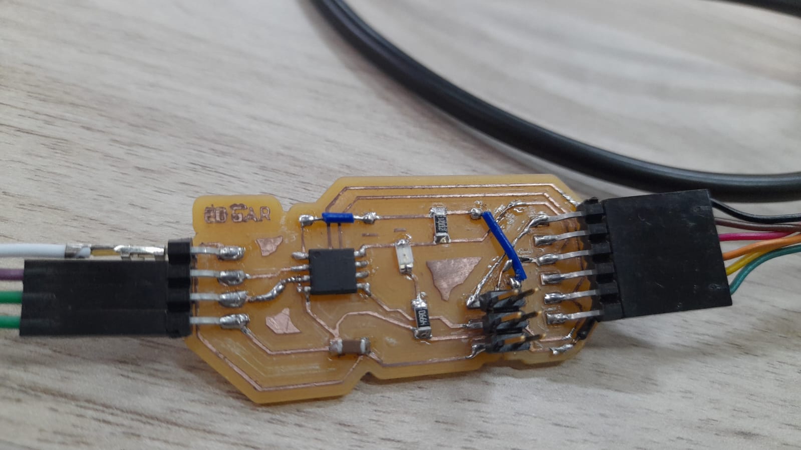
After having my board made I started haunting for components.
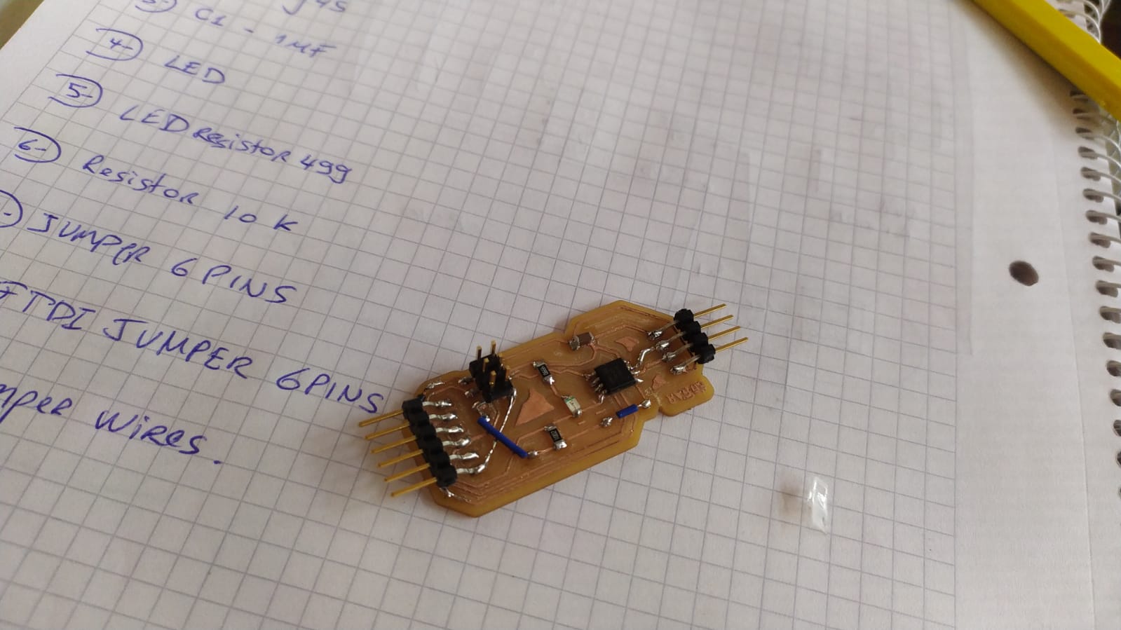
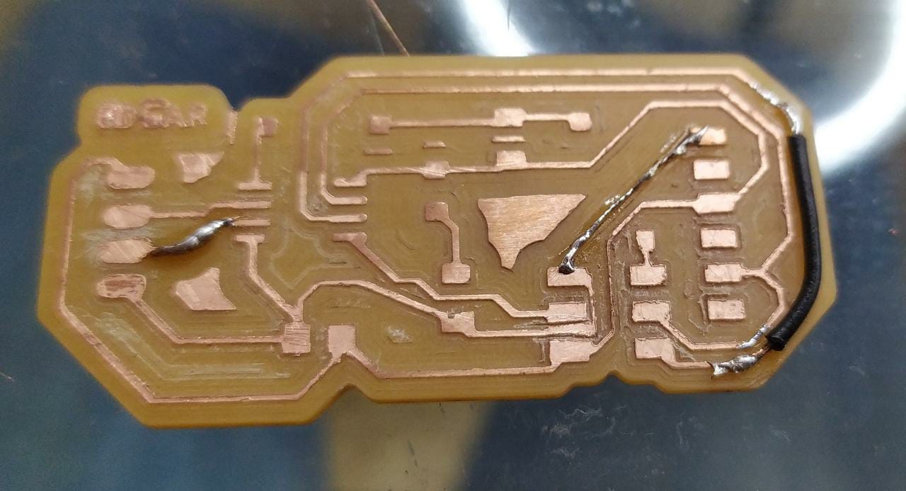
Got all components and the soldered them to the board, then used a multimiter to controll all the connections, and realized there was no continuity in some portions on the track.
fixed them with some copper wires and solder tin and everything was ready to go.
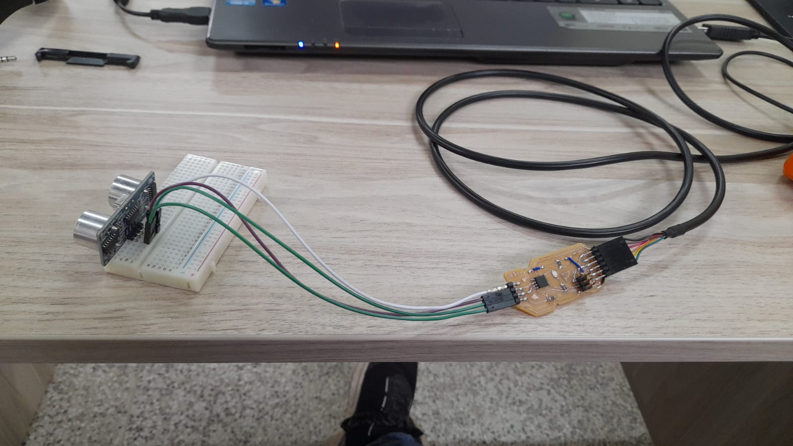
I used a small protoboard to connect my proximity sensor and tried to upload the program.
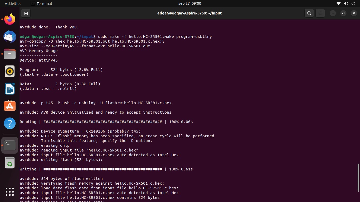
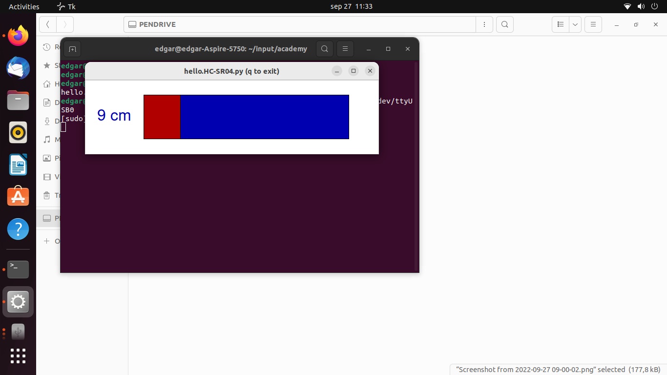
at first I tried to use the same code in Fabio Ibarra´s Page, but the python code in his page throwed an error, So I checked again the fab academy´s Neil Example.
This code worked really well and didn´t have much trouble later on.
As you can see in the last picture everything went down as expected from this place on.
I used my notebook to test the sensor and it all worked fine.