8. Computer controlled machining
Group assignment: - Complete your lab’s safety training - Test runout, alignment, speeds, feeds, and toolpaths for your machine - Document your work to the group work page and reflect on your individual page what you learned
Individual project
- Make (design+mill+assemble) something big
Learning Outcomes
- Demonstrate 2D design development for CNC production.
- Describe workflows for CNC production.
Have you answered these questions?
- Linked to the group assignment page.
- Documented how you designed your object (something big).
- Documented how yo made your CAM-toolpath.
- Docomented how you made something BIG (setting up the machine, using fixings, testing joints, adjusting feeds and speeds, depth of cut, etc.)
- Described problems and how you fixed them.
- Included your design files and “hero shot” photos of final object.
| Thursday | Friday | Saturday | Sunday | Monday | Tuesday | Wednesday |
|---|---|---|---|---|---|---|
| organicing my week, studying the lesson and documentation | group assignment of the week safety class and documentation | 3D design of the individual assignment and CNC machining it in the afternoon | Study and improve documentation skills | Documentation and working on my final project | Catch up with the documentation from previous weeks in order to fullfil the course standards. | class and next week timetable organization |
Group Assignment
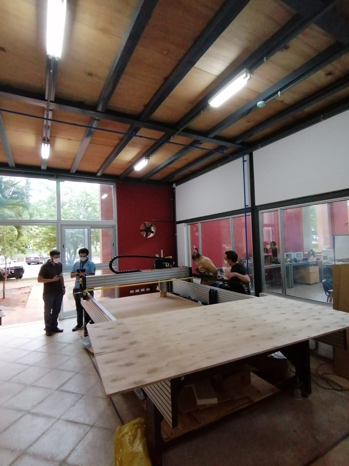
The machine we have at our lab is the Shopbot PRSalpha.
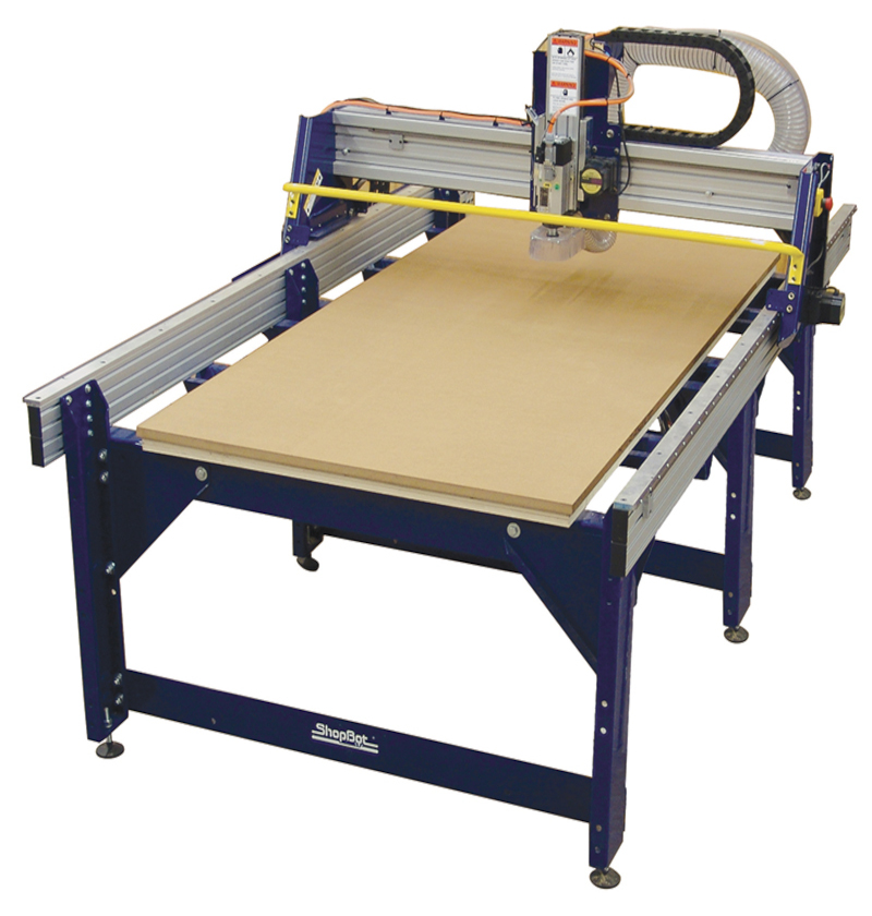
All the information about the machine can be found at: Shopbot´s webpage.
A few safety measures
- Ensure safety glasses and ear protection while operating the machine.
- Ensure that you wear a proper shoe or safety boots in the work area.
- If you have long hair, keep it covered when you operate the machine.
- Keep your hands and body away from any moving parts during the machining process.
- Dont wear jewelty or any loose clothes.
- Never try to reach in the machine while it´s running.
- Never leave the machine alone when it´s not completely powered down.
For the group assignment we recieved a talk from our instructors, and later we started to cut a few test to see the speeds and feeds and we learned the difference in cutting from the upcut and downcut 1/4 inch bit.
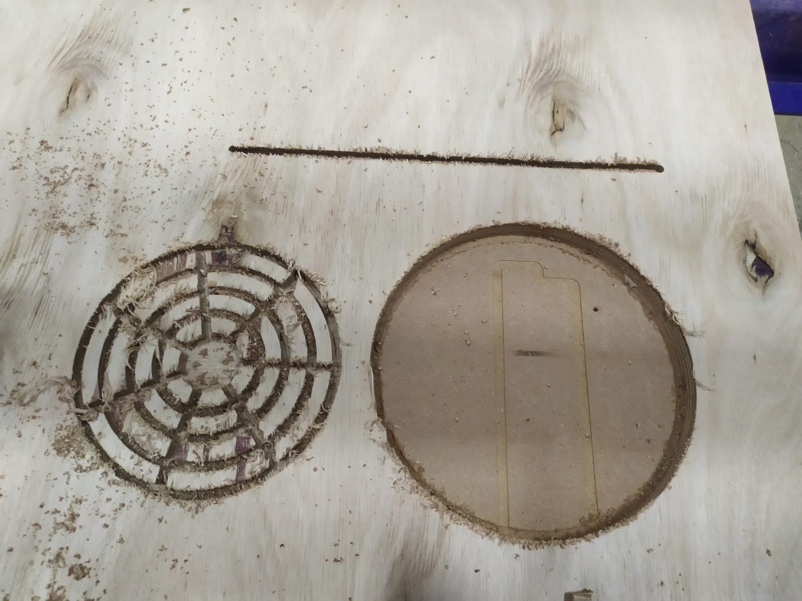
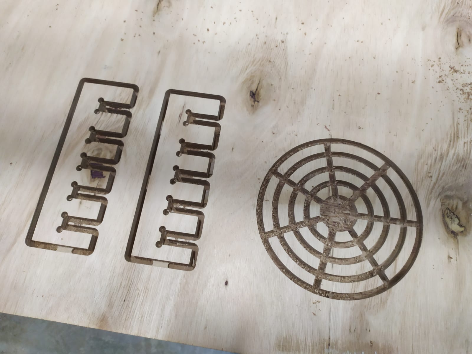
To start we used and upcut bit at 6000 mm/min feedrate, and 10000 RPM from the spindle, our spindle is a 4HP air cooled one. the first thing we cutted was a circle and a line, and later we did the concentric circles test as showed in the picture.
We tried a downloaded pressfit test but it was designed for a material with a diferent depth, later we repeated the task with another design.
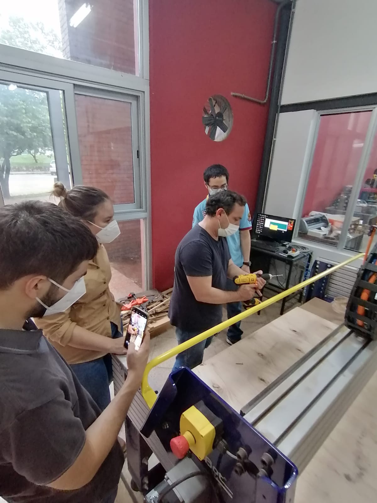
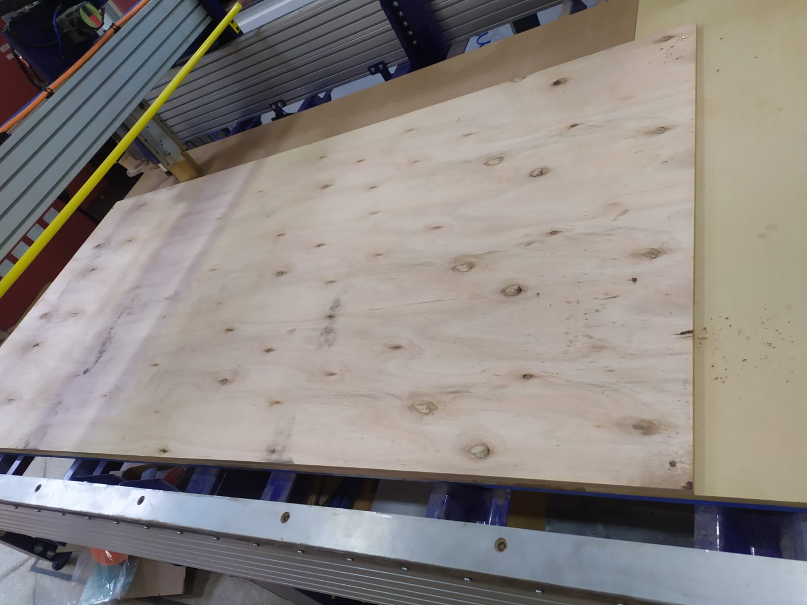
To ensure that the plywood sheet didn´t move while cutting, we used screws wit a cordless drill, the first step is to make a hole in the plywood and the second step is to put the screw in place.
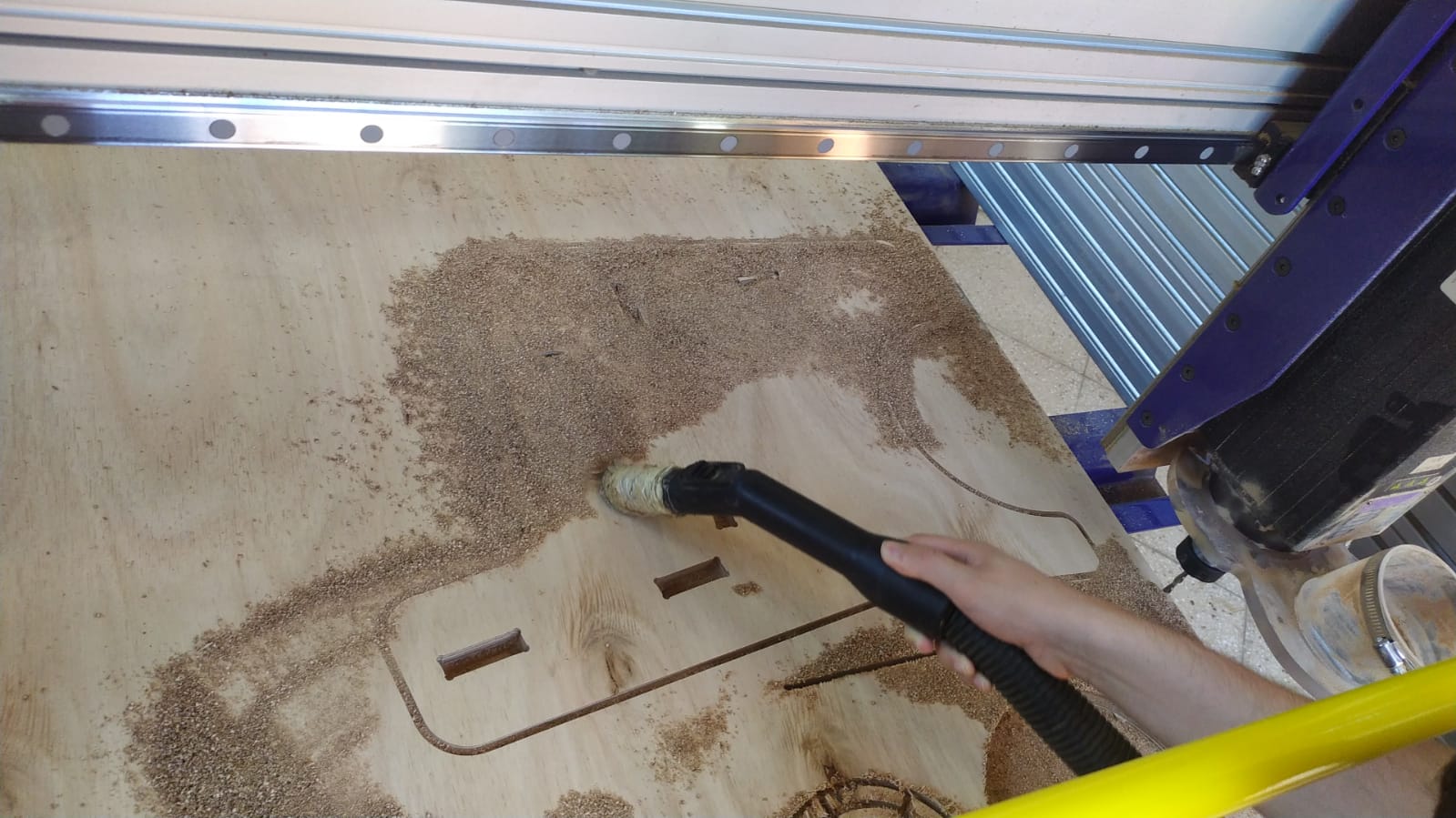
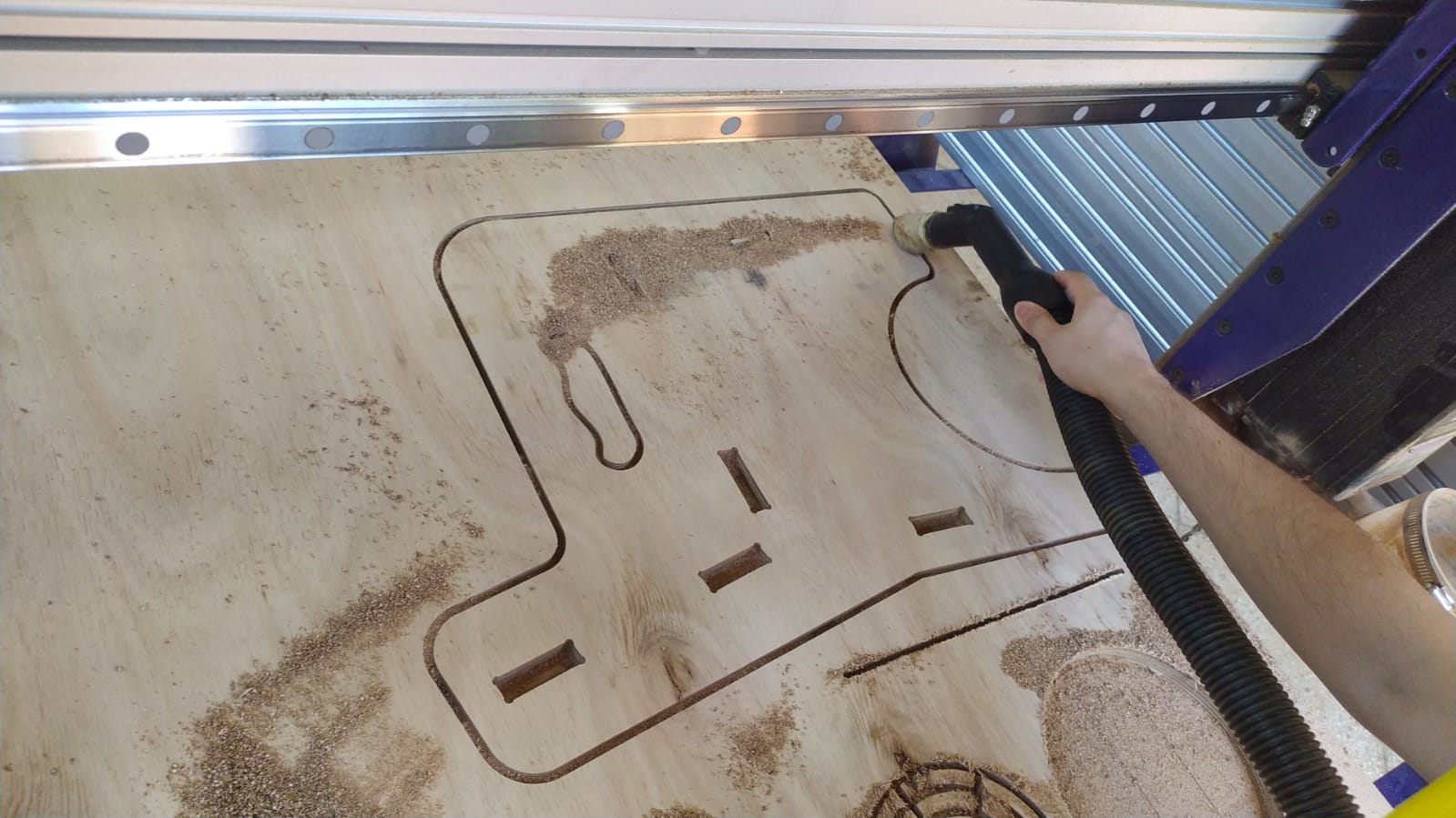
before we putted the plywood in the machine, we cleaned it up so that it wouldn´t have any dust or remaining things that can deform the plywood and vary its height wile cutting.
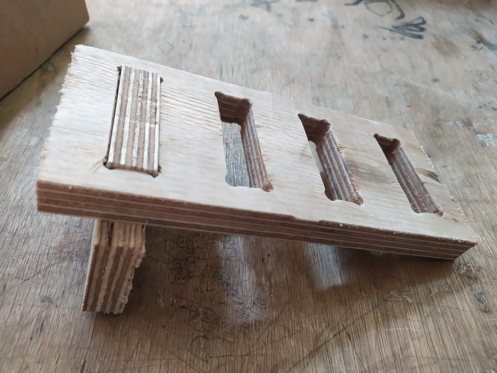
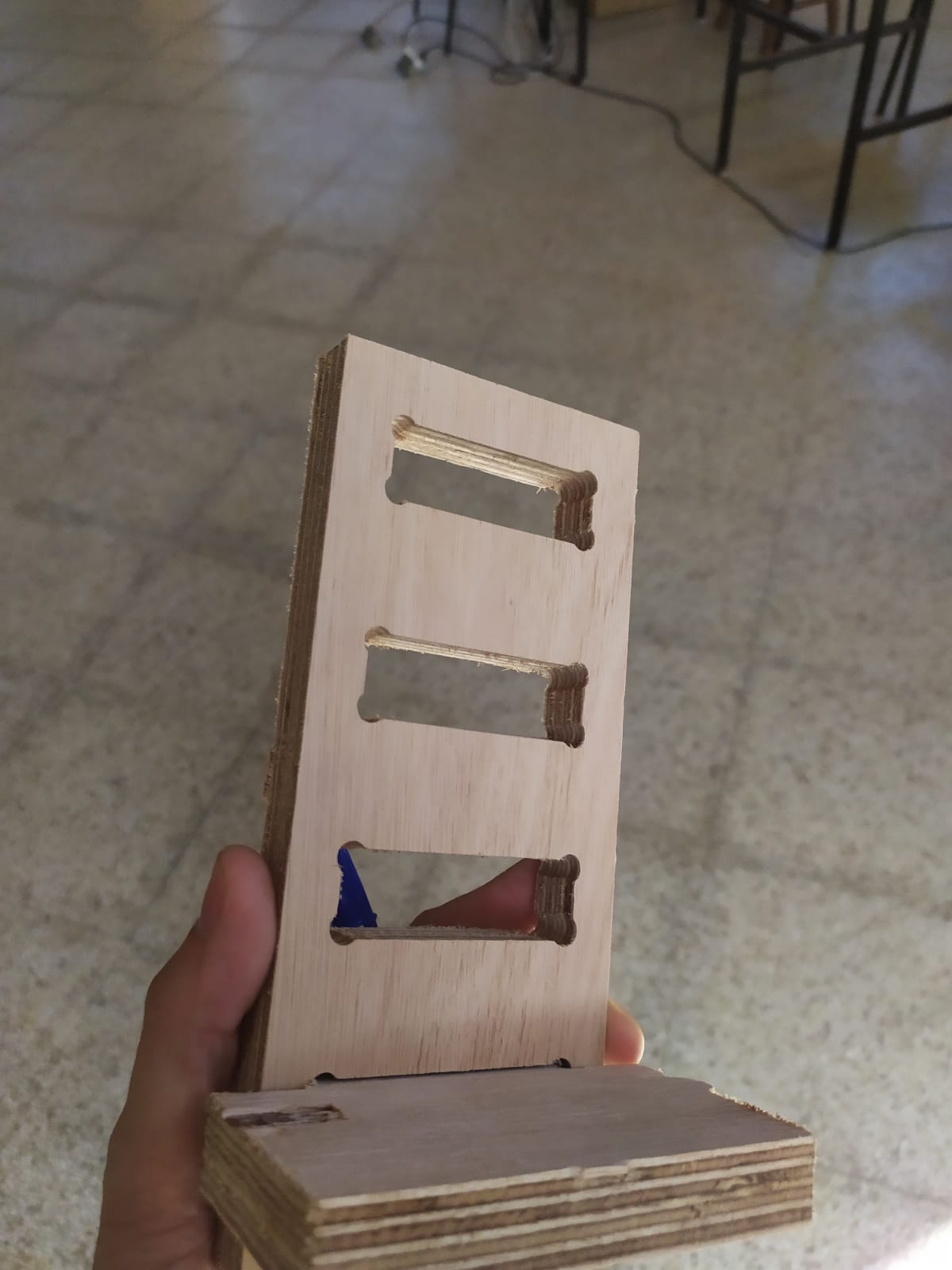
We did a pressfit test to fint the right tolerances for the furniture sockets we were going to design, I personally used a 0.2mm tolerance in each direction, for a very strong pressfit.
3D Design
I used a 60.4 mm slot, so that a 60mm plywood would be a perfect fit. Using this idea and parameters, I made my design.
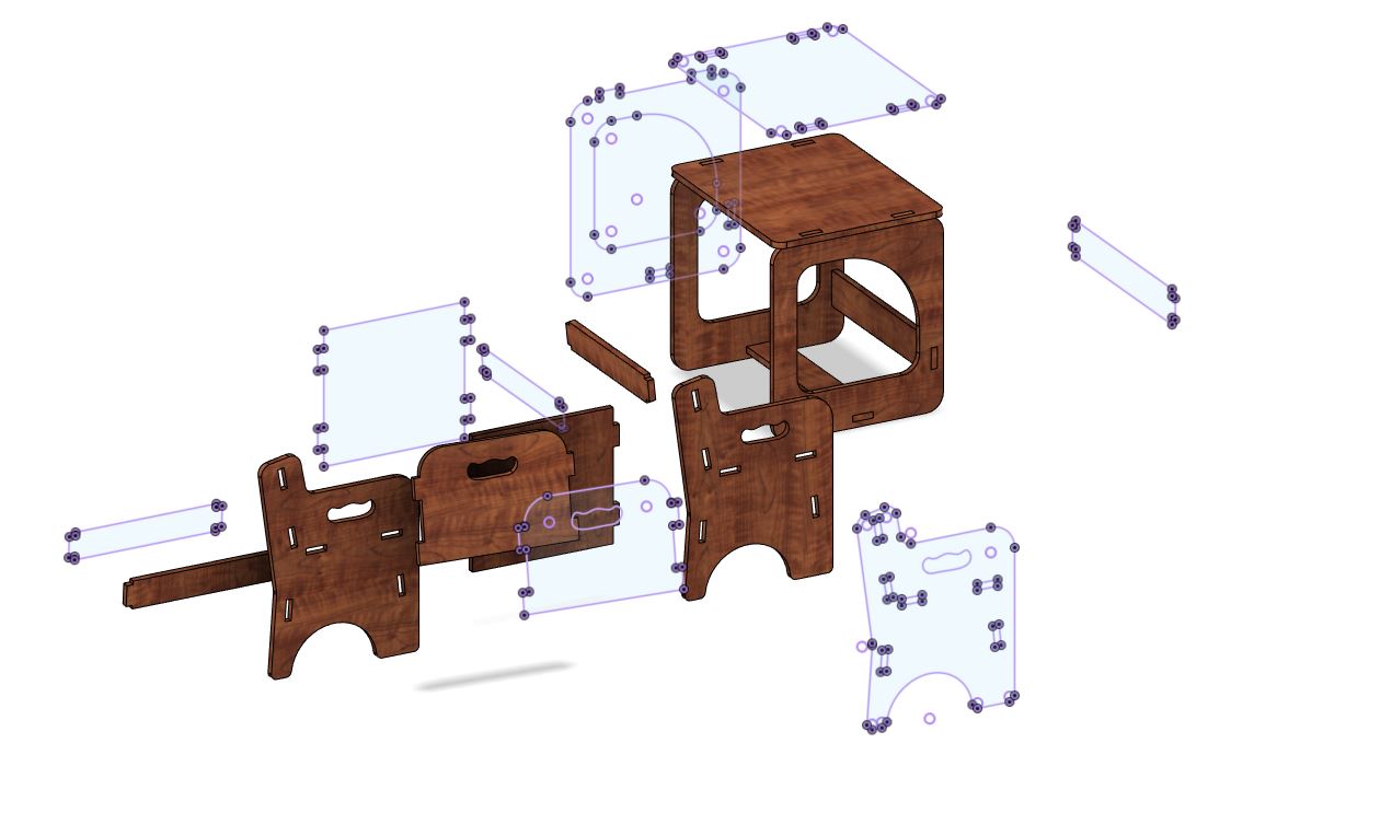
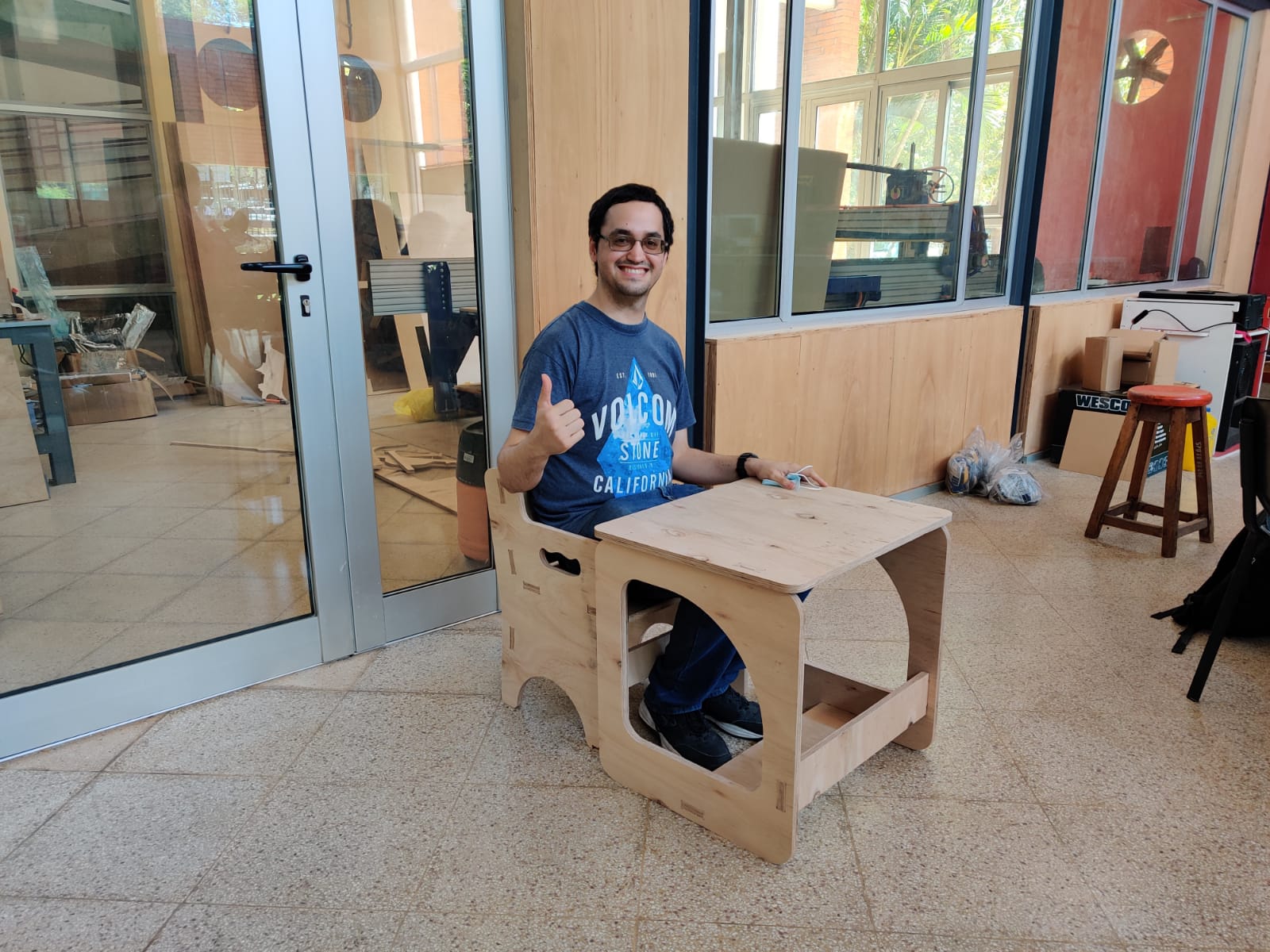
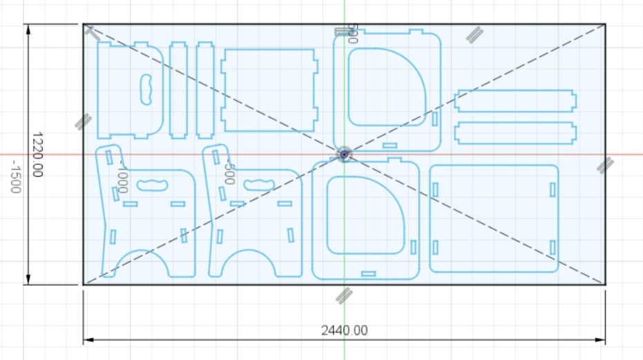
I have designed this small chair and table for my daughter, for the design I used fusion 360 and ordered all of the pieces to be able to cut them in 1 full sheet of 18mm plywood.
after finishing the plans, we used vectric Vcarve PRO as a Cam software for the Shopbot, I downloaded a gadget to make the dogbone fillets, so the pieces will fit togetter.
Cam Software
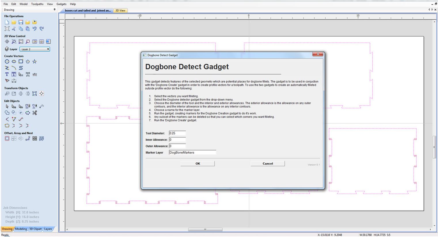
Vcarve Pro´s Automatic Dogbone Gadget.

In order to use the gadget first we had to use the function dogbone Detect, and that will create a drawing on the selected toolpaths of our design.
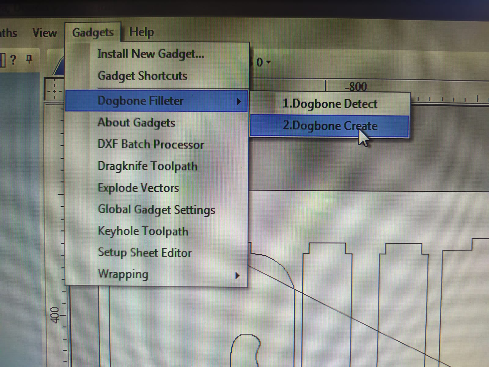
Once it detects it, you can choose to use Dogbone or Tbone fillets, I personally prefer dogbone fillets, but it doesn´t make much diference to use one or another.
3D design files
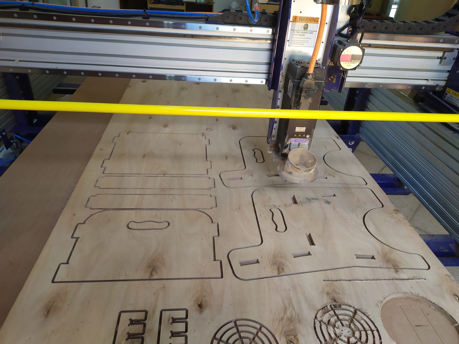
Shopbot Machining.
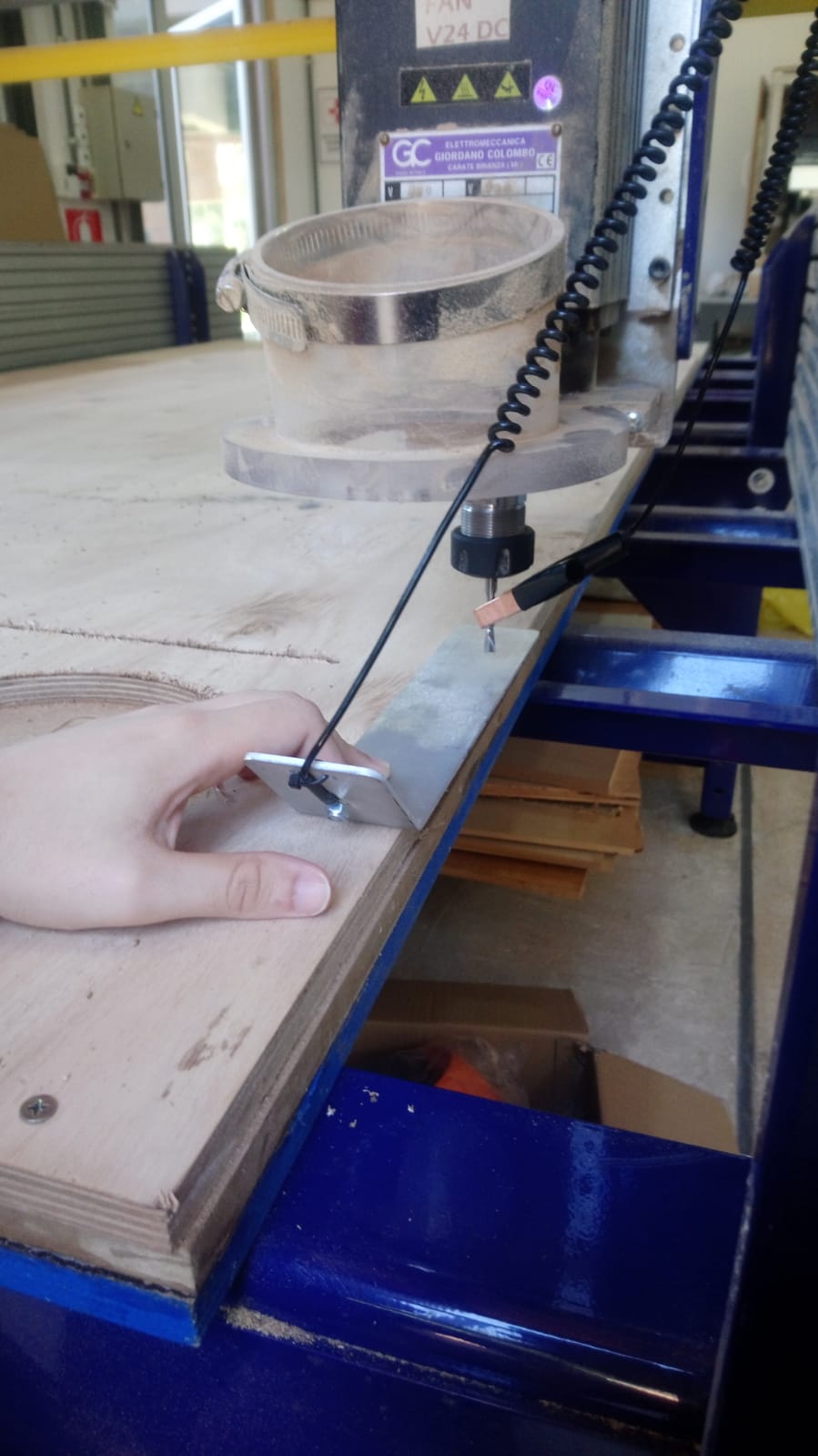
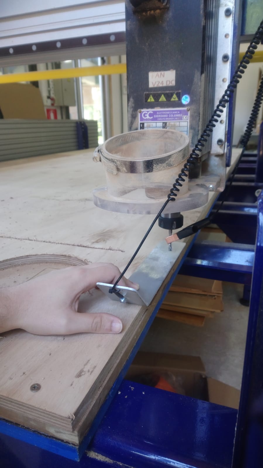
The shopbot has a probe to measure the correct z height before cutting. you have to use a metal clamp to put at the end of your bit, and the other side is a piece of metal conected to a cable, it works as a sensor by closing the circuit on contact, this assures you, a proper Z calibration of the machine.

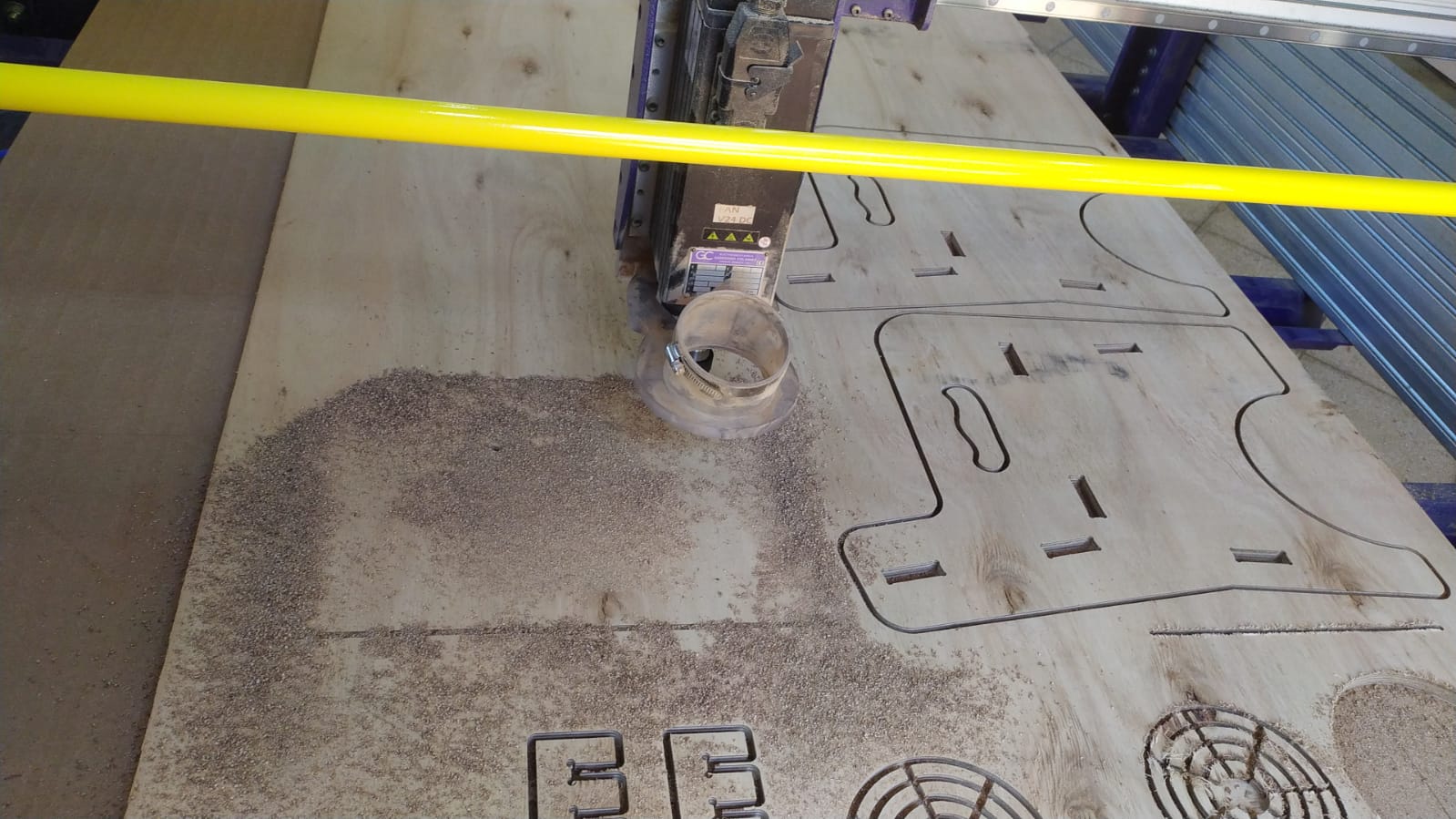
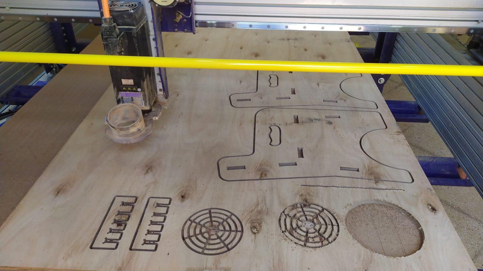
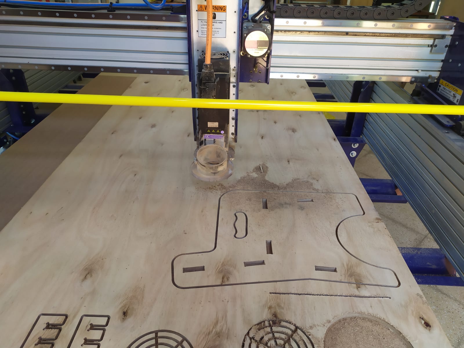
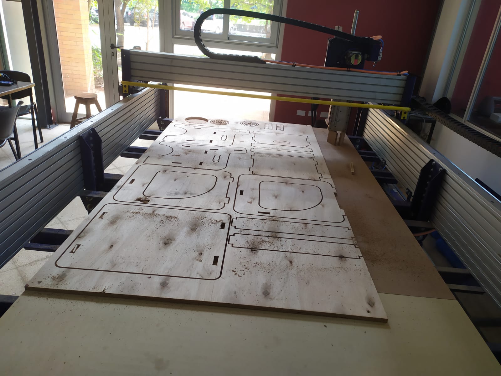
The cutting process took around and hour and a half but was made one by one, (because I was afraid to mess it up all at once hehe..)
One thing that surprised me was that the X axis of the machine is 90 degrees Rotated from most machines I normally use. Making the larger axis actually the X axis instead of Y.
Here is the final product, I´m very happy with the result and got to learn a lot about the shopbot machine, I was impressed by the Z axis that uses a rack and pinion system with a neumatic aid, instead of the Z ballscrew Systems seen in other machines.
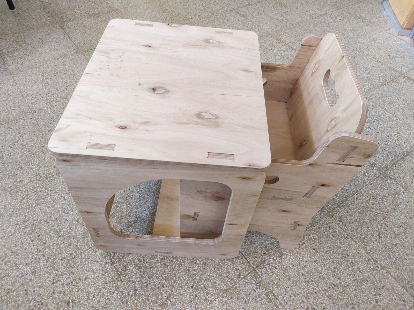
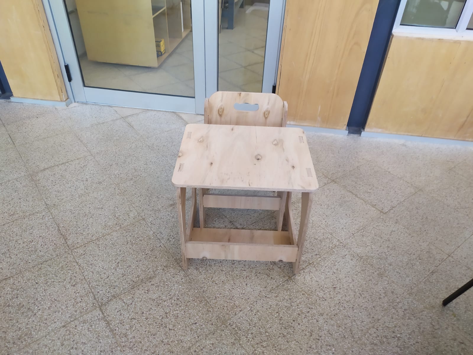
Even though I designed this for my daughter, it came out pretty strong being able to held a whole adult´s weight with no problem, no glues, no screws.