12. Machine design
group assignment - design a machine that includes mechanism+actuation+automation+application - build the mechanical parts and operate it manually - document the group project and your individual contribution
We had a previous meeting to say what we are going to build and the role that each one will have.
The result of the group work is here Machine
My role was the electronic part
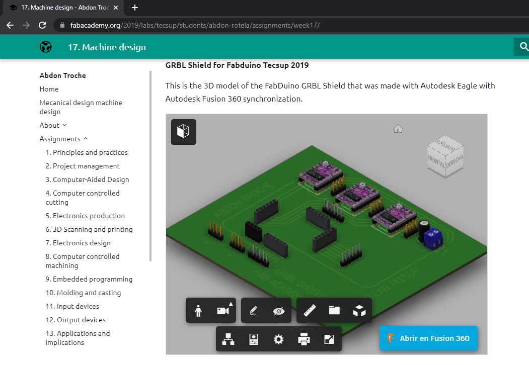
Design of the electrical circuit of the motor controller
The base plate had already been previously machined by Edgar Arévalos based on design by Abdon Troche
I used a circuit already designed by Abdon Troche Fablab 2019 (Fabduino) and made a modification to it by resizing the board and changing the source connector from PINHD 1X02 to a JACK.35mm, all changes were made without changing the reference pins used to join with those of the base plate.
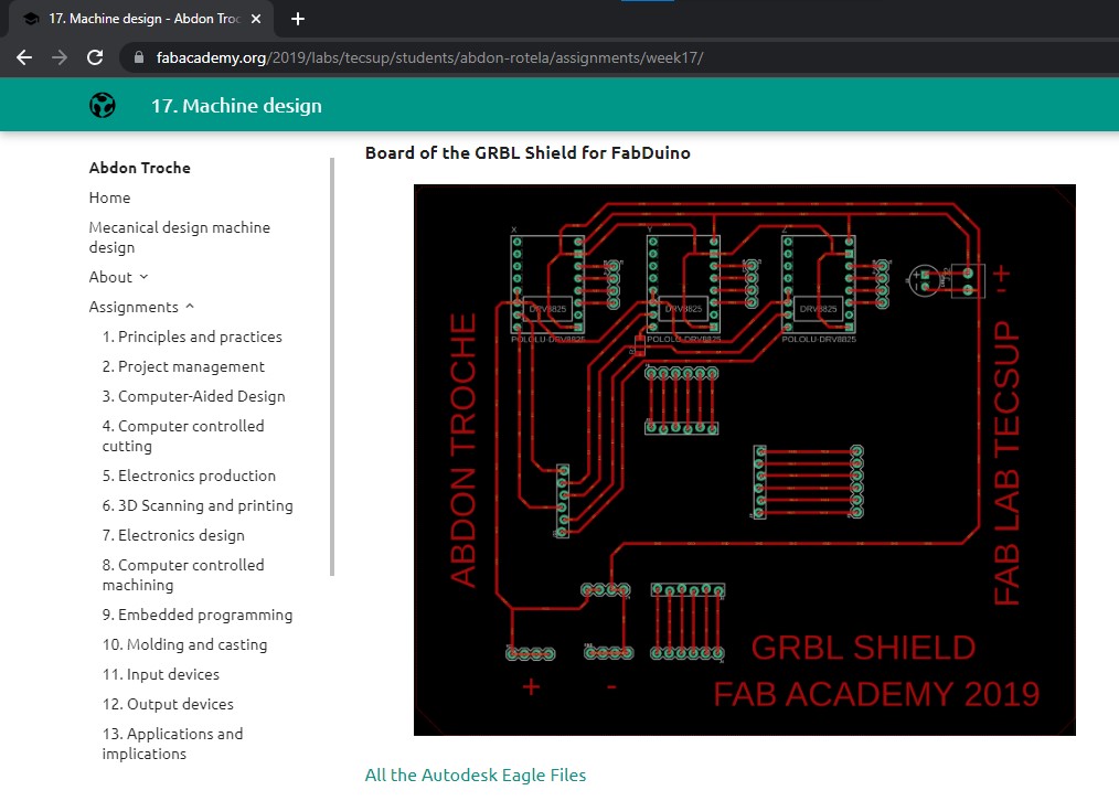
Once the modifications were made,
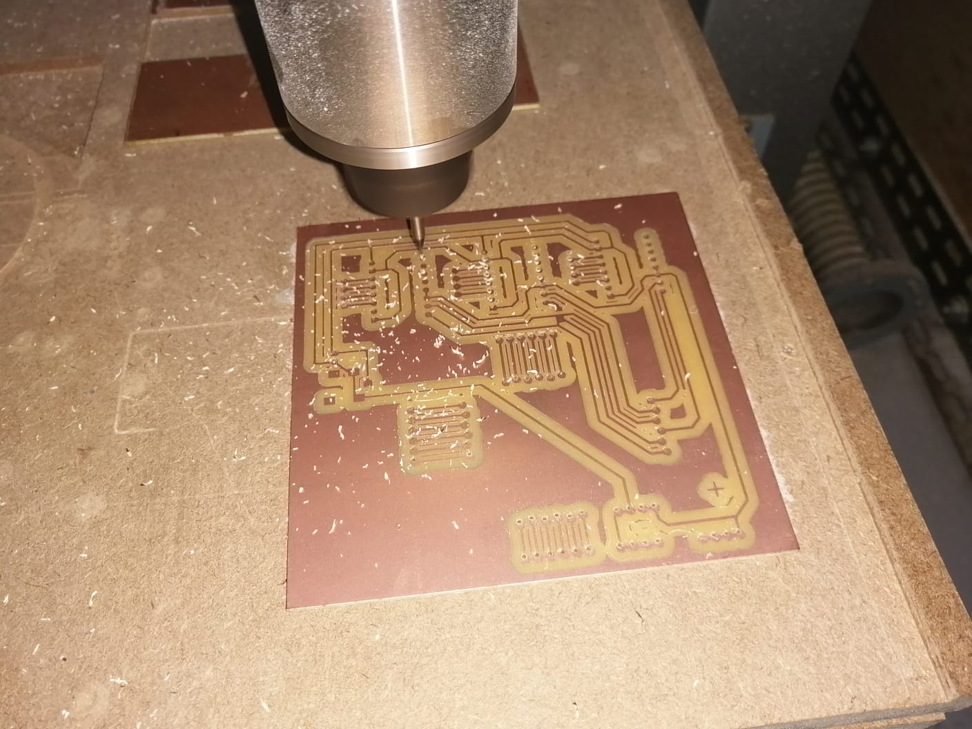
I generated the Gerber file to then send to the CNC and machine. I got this result
First problem:
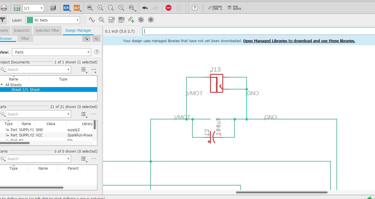
I had to modify the schematic because I should have inverted or mirrored the layout in FlatCam, to match the motherboard
Second problema
As the board uses components that pierce it, different from surface components (SMD) that are soldered on the surface. I noticed that the holes were missing
third problem
I managed to include the holes in the code but some pin holes were misaligned. I looked at the schematic design of Eagle and confirmed that there too they were misaligned.
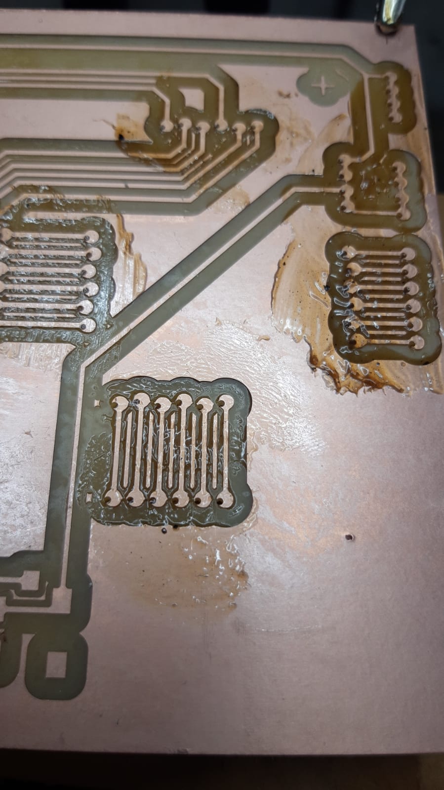
As a strategic solution, I had to manually align the holes
Thanks to these problems I learned two things:
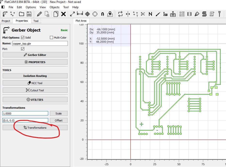
First, How to invert the circuit or apply the mirror mode: in the FlatCam program there is the “Transformation” option, this opens a windows in which we select “Flip on X”
Step one:
Step two:
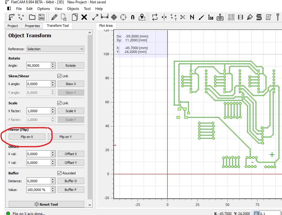
I must repeat this process, that is, do it individually for both the Cooper tool and for the holes.
Second,
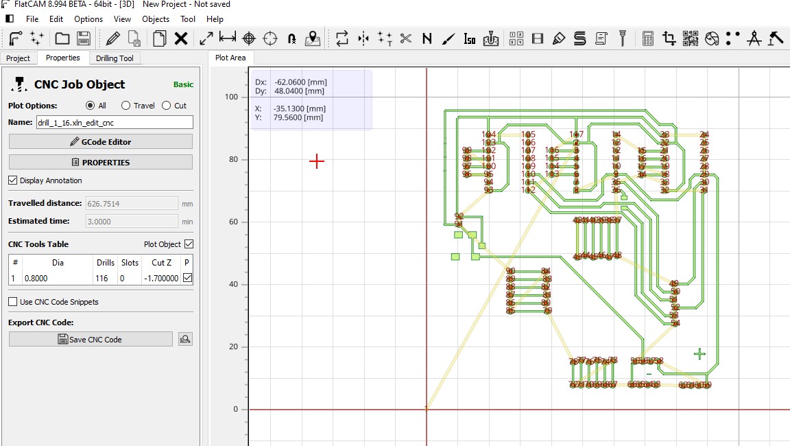
I learned how to create the Gerber with the holes on the board: Actually when creating the Gerber in EagleFusion it automatically creates the gerber for the holes as well
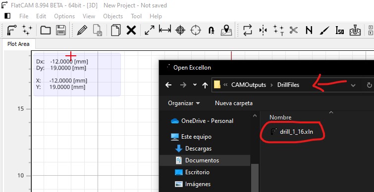
From the FlatCam we open the file generated by the Eagle and,
Step one: Instead of selecting the Open Gerber, we select Excellon
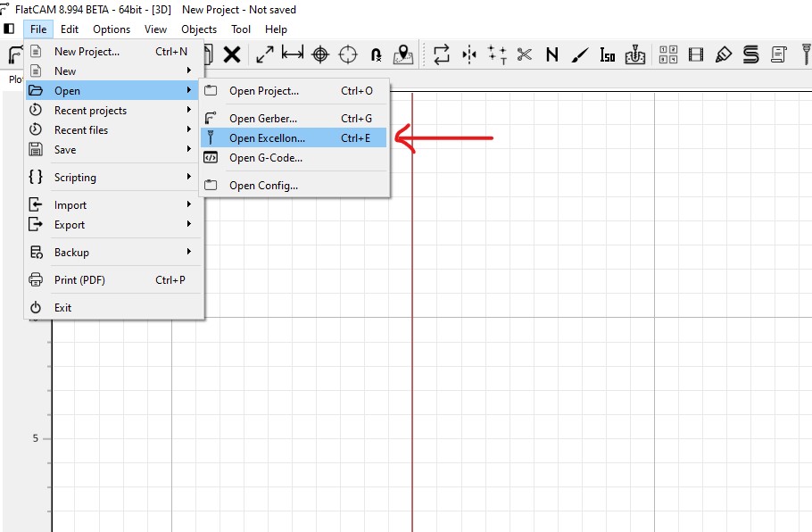
Step two: In the folder generated by the Eagle we select DrillFiles
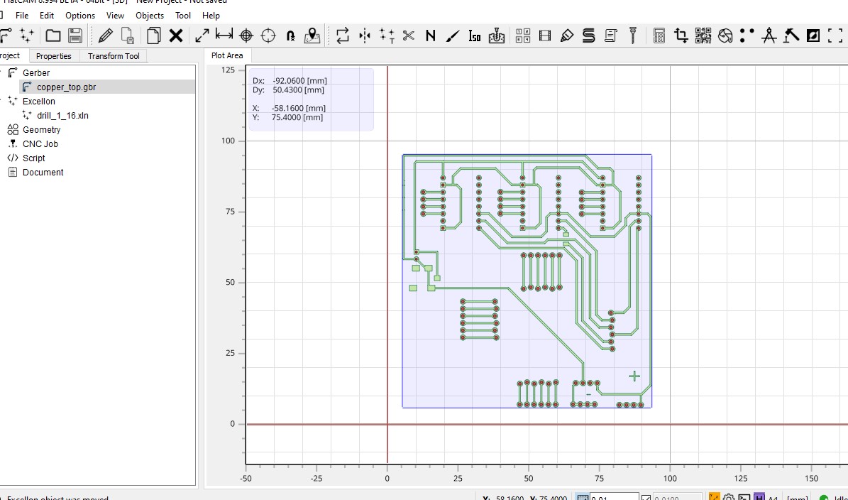
This should match the Gerber of the circuit When making the mirror image of the circuit and the holes, I see that they do not coincide
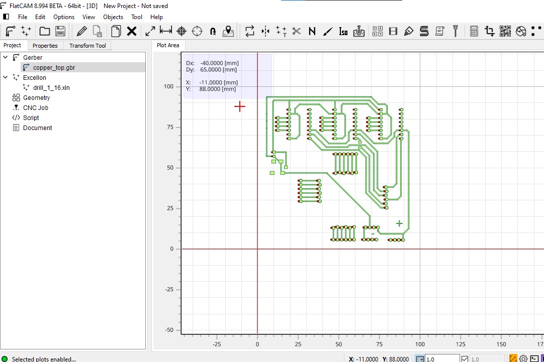
And I have to adjust it manually.
Result:
Regarding the holes, I had to make some modifications regarding the table of tools: Unify the diameter of the cutter to use at 0.8, I did it in “Excellon editor” because only there it allowed me to change the parameters.
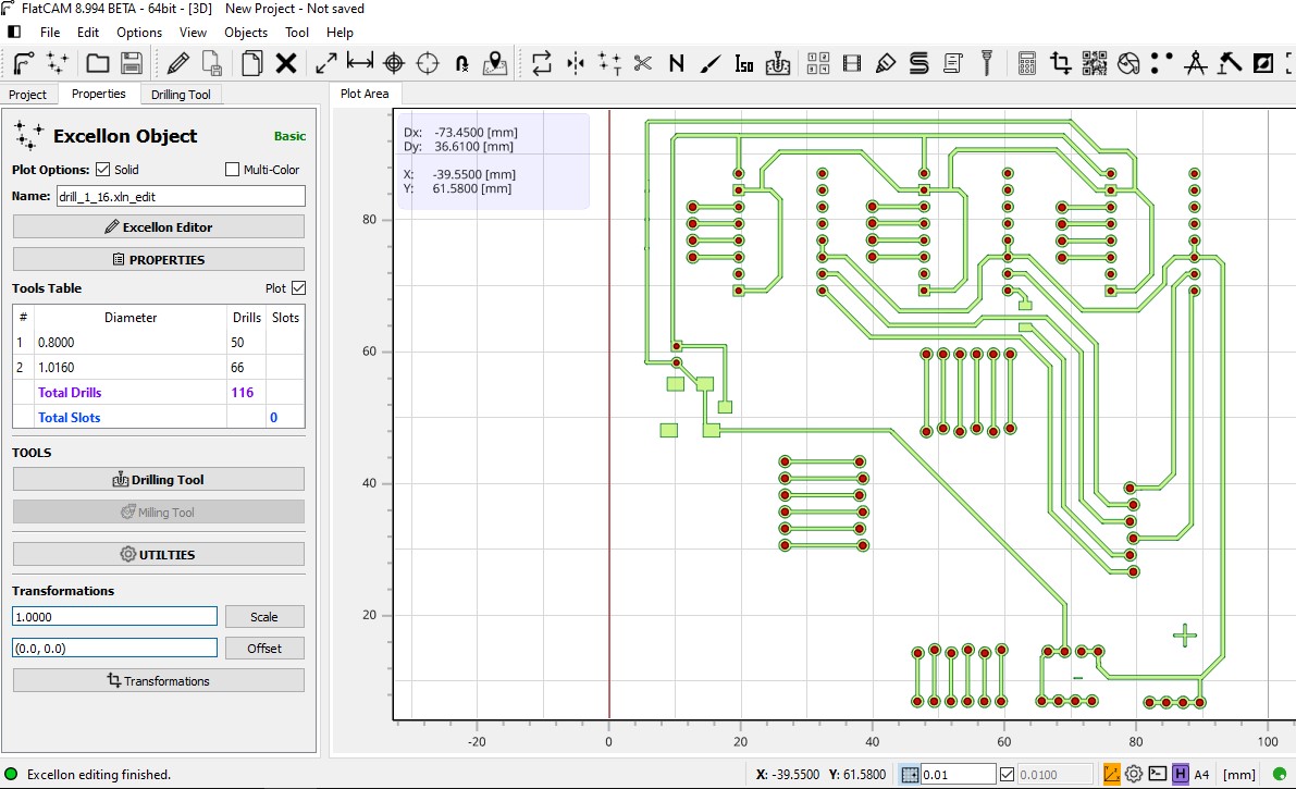
And finally, in drilling tool where the tool order option is, select Forward
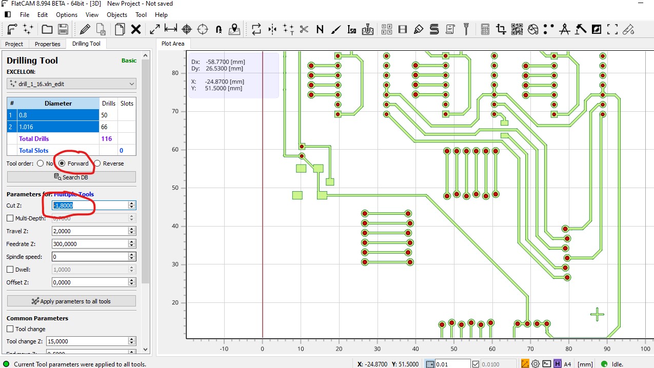
in this way I managed to include all the holes (that was not very clear to me)
In that same window I changed to -1.9 the depth of the Z so that it drills the plate (thickness of the plate) and the speed of the axis 12000 I used a 1/32 round bur.
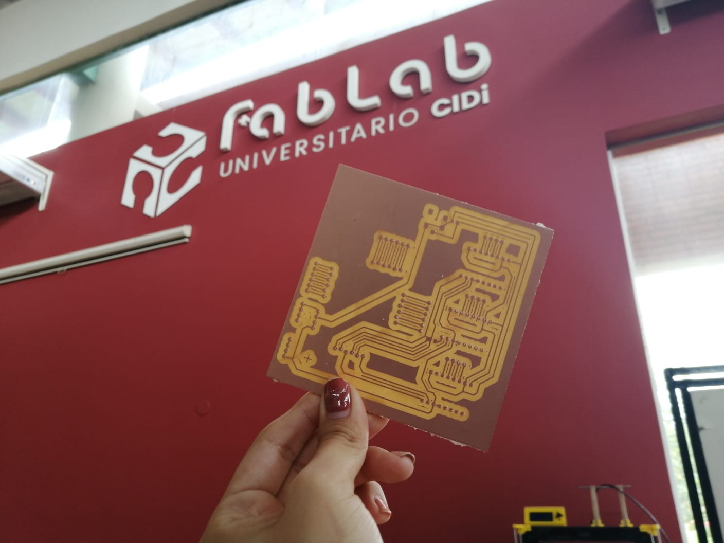
In the end this board was not used for this task Edgar, my classmate, was able to use it for his final project. Had to do some tinkering to the holes to make them match the other circuit.
File
What did I learn working together?
Although my contribution was very poor for that reason, it was very interesting to work on a project all together.
We had a first meeting where we decided what each one’s contribution would be.
The result was very interesting and working as a team can achieve very nice things.