13. Input devices
assignment individual assignment: measure something: add a sensor to a microcontroller board that you have designed and read it group assignment: probe an input device’s analog levels and digital signals
Individual assignment
I chose a sensor that I will use in my final project. The 6-axis MPU6050 (acceleration x,y,z / gyroscope x,y,z)
I divided my work into three parts:
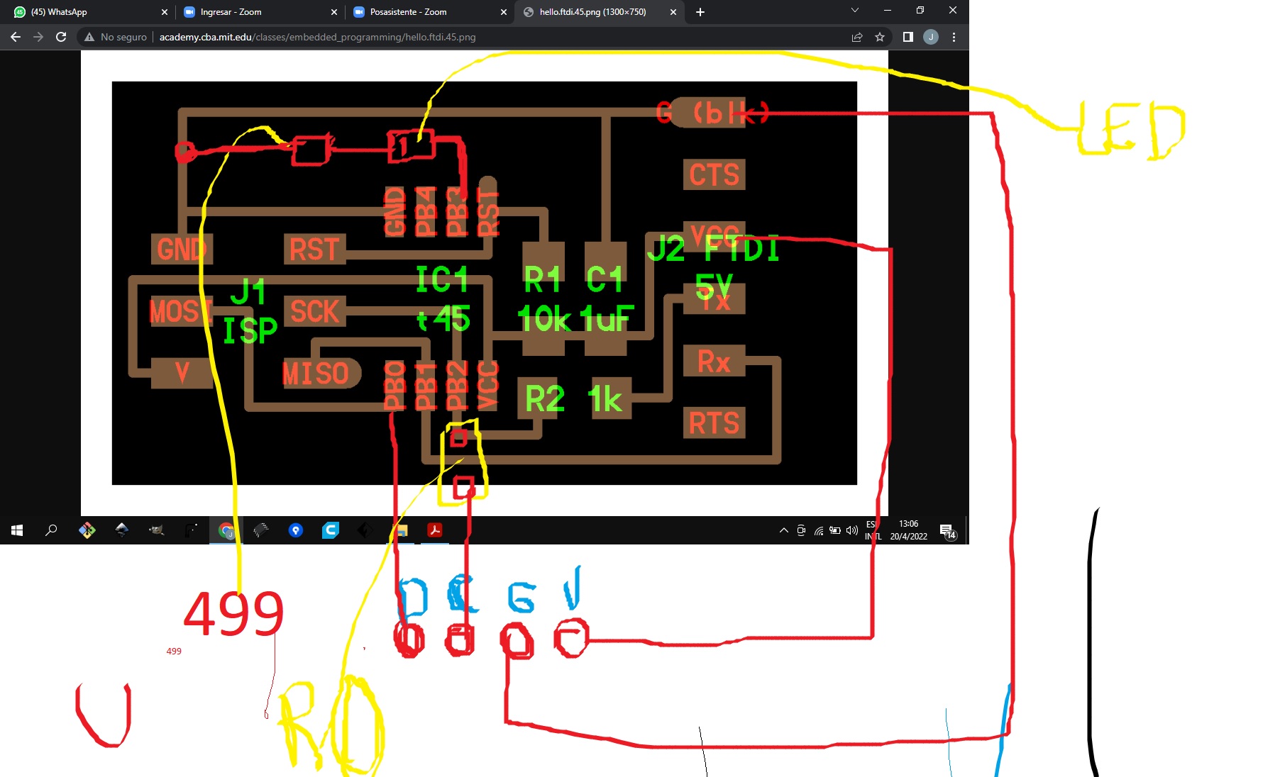
1- choose the elements to use to create the integrated circuit board
2- Manufacture the integrated circuit board, which implies: - Make the design of the plate with the program Eagle Fusion 360 - Machining the plate - find the components and solder to the board
3- Test the board by programming it with the PCI programmer: - Do the blink Led test - Search and load the libraries to the arduino program to read the MPU6050 sensor - Read the sensor and test it by moving it in all its axes
Coments
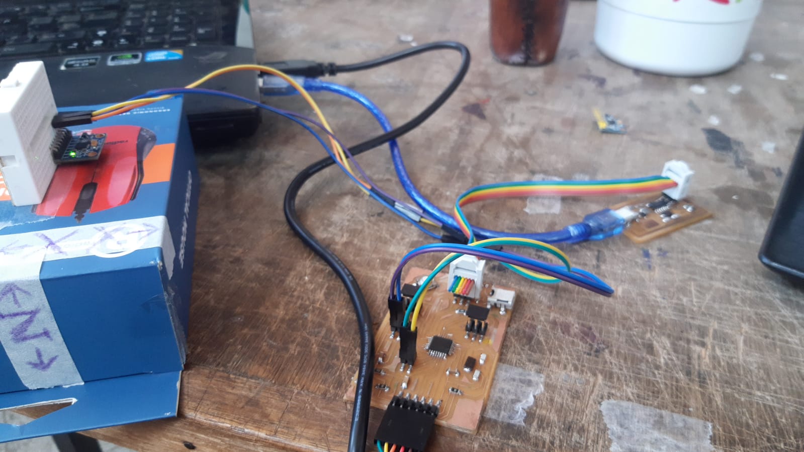
When testing the board with the atTiny45 microprocessor, it was not easy to program it and for this reason I decided to use another board, already made in the previous task (output device), which contains the atTiny328 (Danduino). This did work and I managed to read the sensor
Development of the individual assignement
1- choose the elements to use to create the integrated circuit board
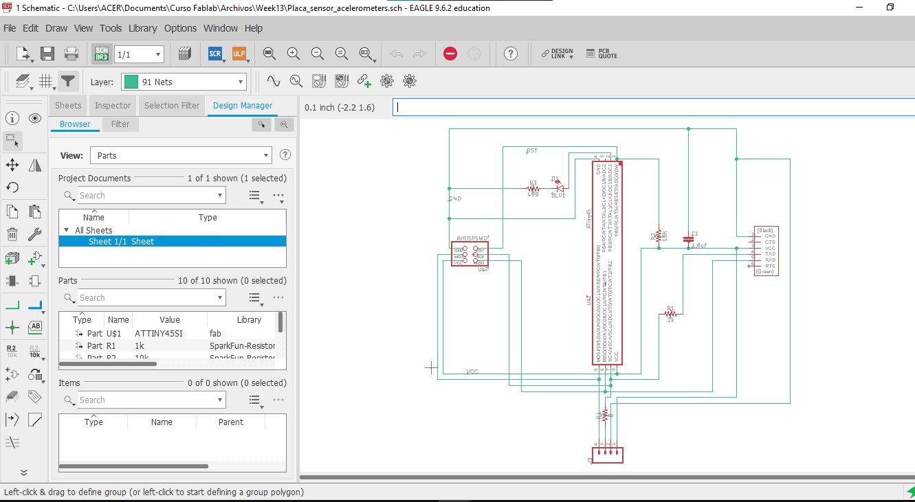
Schematics eagle fusion here
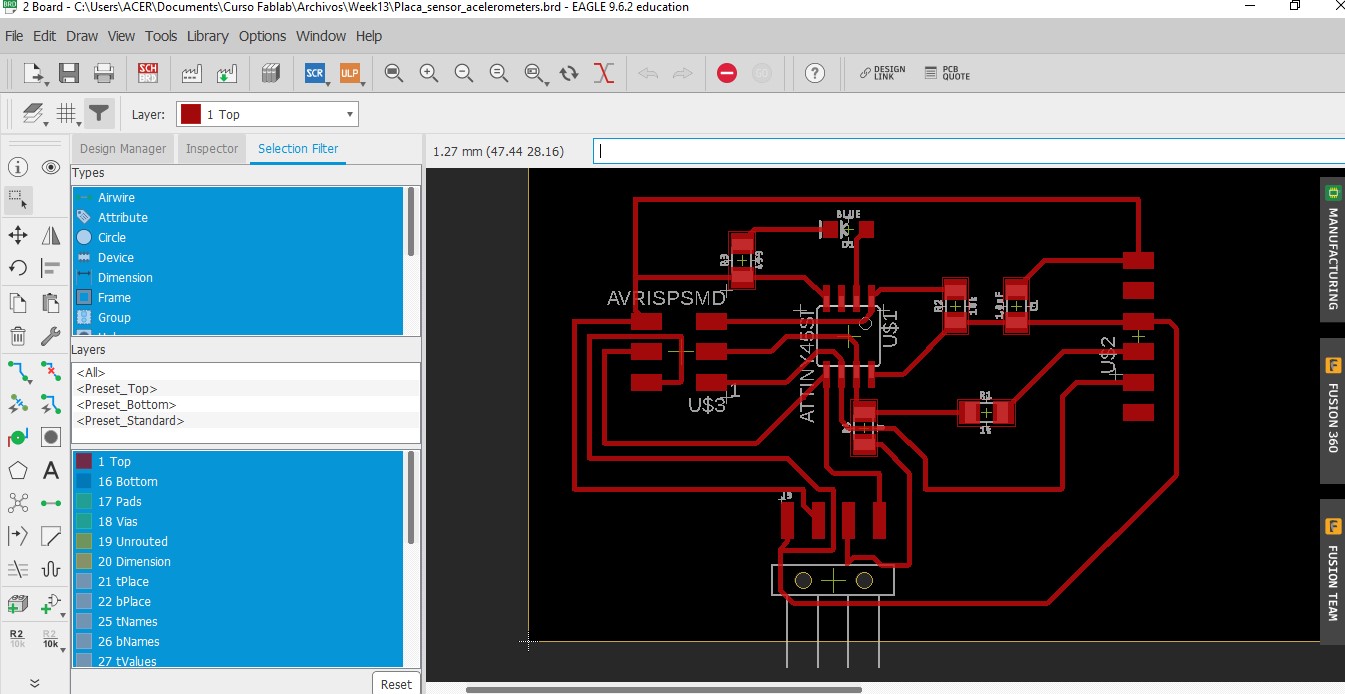
2- Manufacture the integrated circuit board, which implies: - Make the design of the plate with the program Eagle Fusion 360
Gerber files for FabLab and Code for CNC
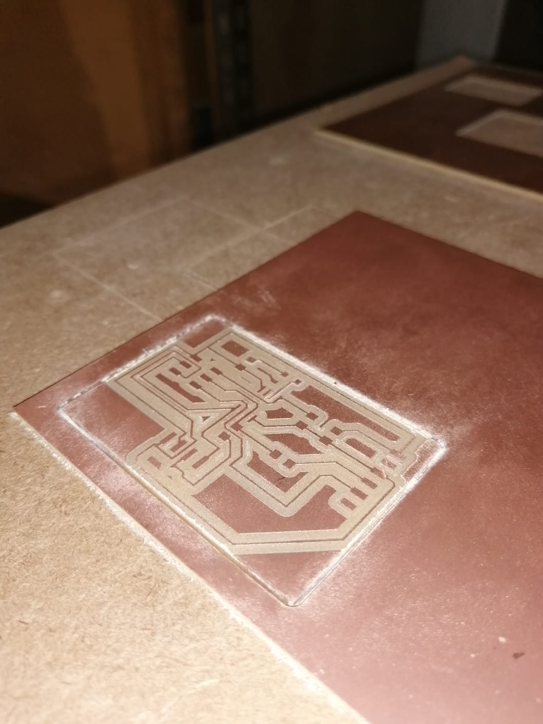
- Machining the plate
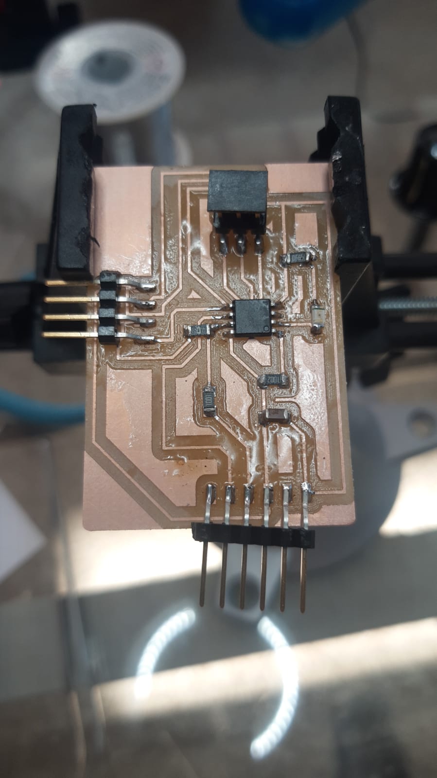
- find the components and solder to the board
3- Test the board by programming it with the PCI programmer: - Do the blink Led test
- Search and load the libraries to the arduino program to read the MPU6050 sensor
First I tried to read the sensor with the arduino nano and for that I looked for tutorials and found a tutorial that included libraries
Tutorial for conection MPU6050 to Arduino
I looked for some ready-made code to connect the sensor to the atTiny45 but I couldn’t. For this reason I used a board that I manufactured in the output device task (Danduino)
So that the board with the atMega328p can be programmable with my programmer I needed the library to interface my programmer to the atMega328p. I got it from Abdon Troche’s page (2019 fablab Academy final project)
-
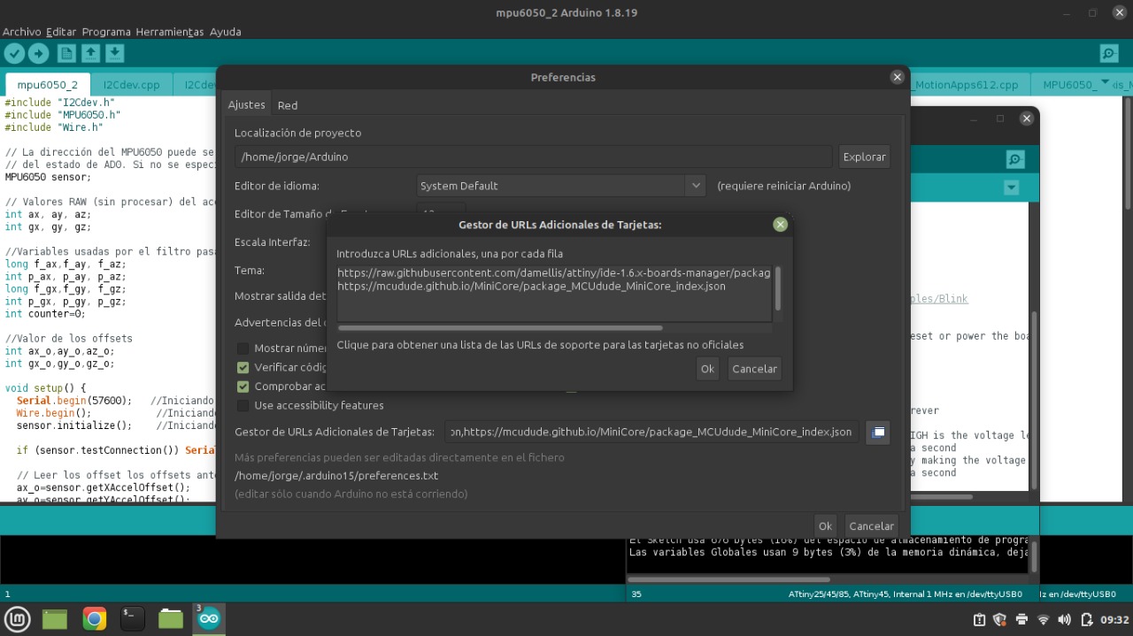
Add the MiniCore library at archive
-
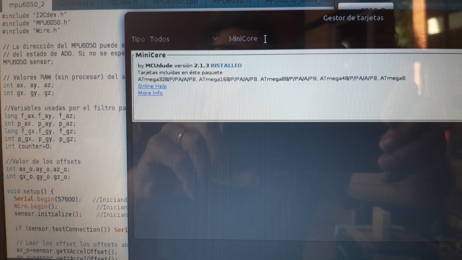
Installing the library
-
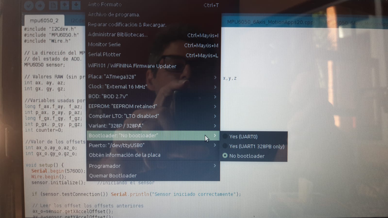
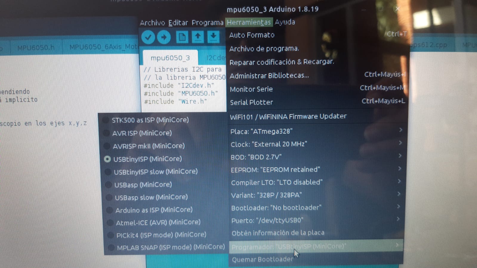
I configure the tools of arduino IDE and less something parameters for default except:
The board
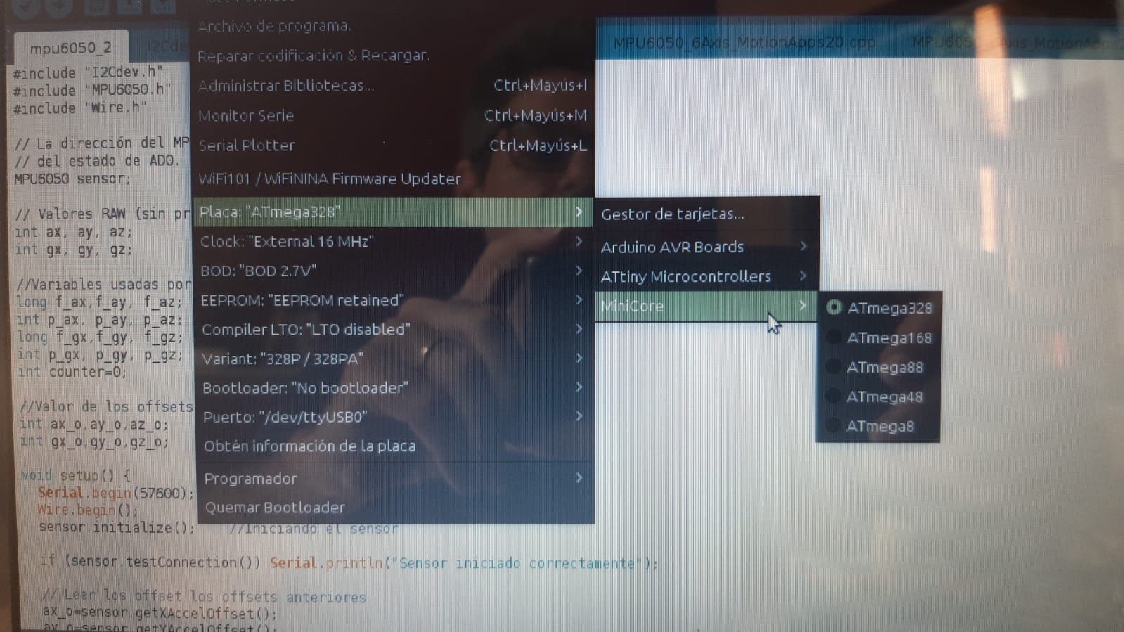
Clock
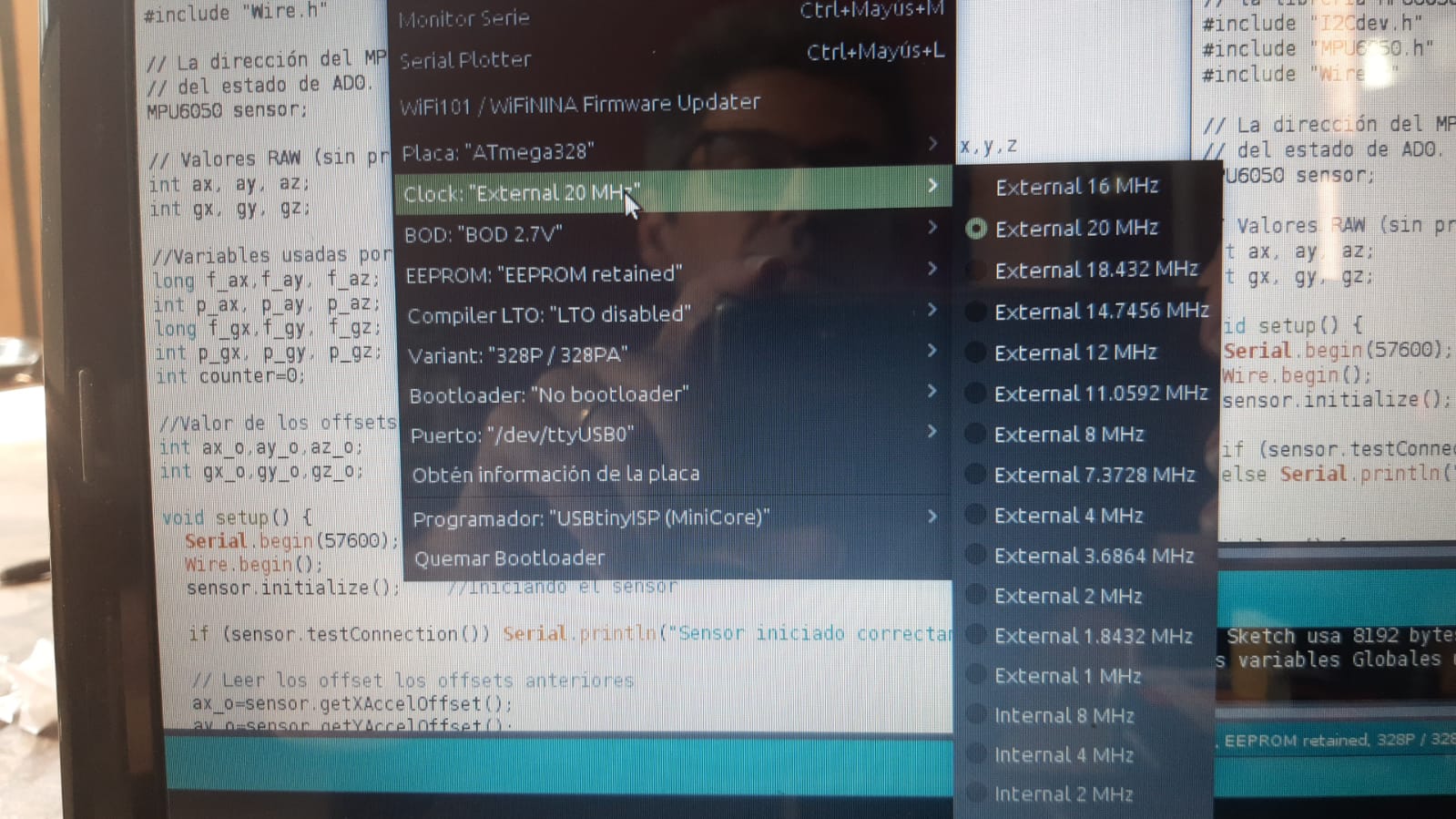
No bootloader
Progamer USBtinyISP(MiniCore)
- Read the sensor and test it by moving it in all its axes
To be able to read the sensor I loaded the codes that I got from the aforementioned tutorial
[Tutorial for conection MPU6050 to Arduino nano] (https://naylampmechatronics.com/blog/45_tutorial-mpu6050-acelerometro-y-giroscopio.html)
Then I Start testing the sensor
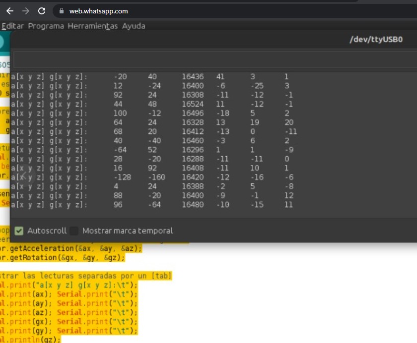
First Code: Charged the first code of the tutorial where I can to see that sensor send information
Second Code: Calibration You must leave the sensor still until you get close to the numbers in the photo
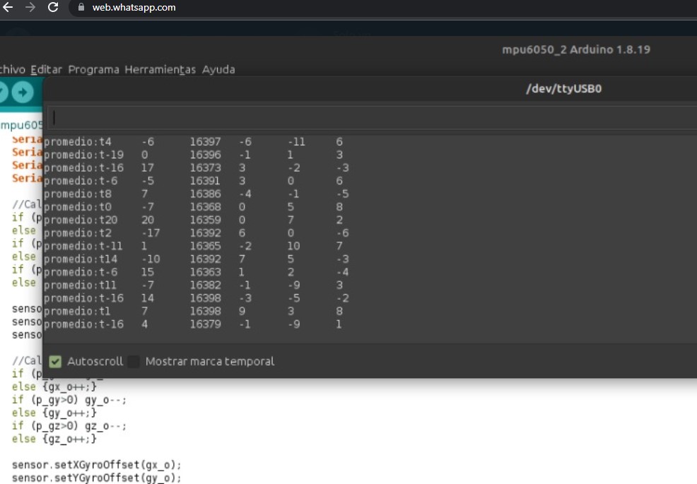
Then Load the first code again to verify the calibration For that I must close the arduino and re-enter.
Third Code
Read scaling
Units of acceleration and angular velocity
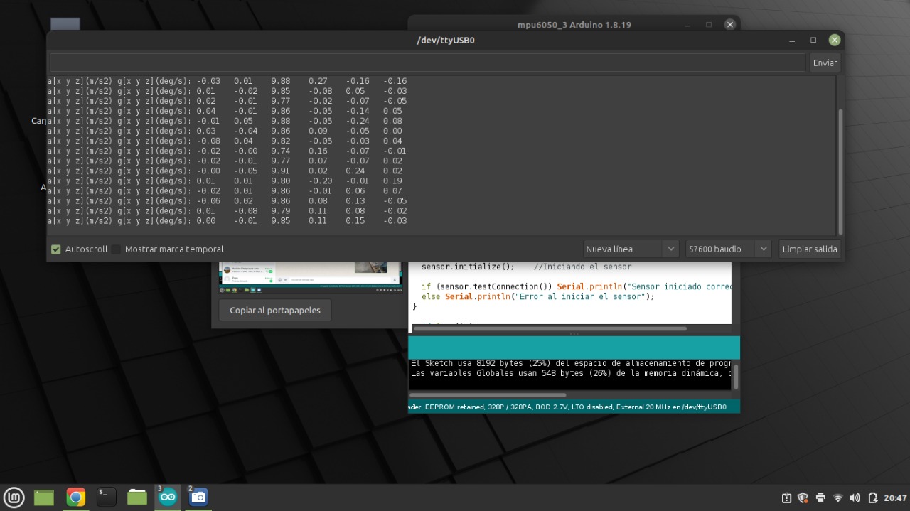
Forth Code Calculating the tilt angle with the MPU6050 accelerometer This works only if the only acceleration present is gravity, but if we move the MPU quickly and without making any inclination, the angle that we obtain with the previous program varies, generating errors for these cases.
Five Code Calculating the angle of rotation using the MPU5060 gyroscope
Sixt Code Implementing a Plugin filter: accelerometer + gyroscope
Experimenting with other codes
We found with Abdon a tutorial HERE
In this tutorial we got a code that met our expectations, thanks to this code we were able to have information about the z axis (yaw) with the angle of rotation.
I share the code
CODE
MPU6050 wire
/*
   Arduino and MPU6050 Accelerometer and Gyroscope Sensor Tutorial
   by Dejan, https://howtomechatronics.com
*/
#include <Wire.h>
const int MPU = 0x68; // MPU6050 I2C address
float AccX, AccY, AccZ;
float GyroX, GyroY, GyroZ;
float accAngleX, accAngleY, gyroAngleX, gyroAngleY, gyroAngleZ;
float roll, pitch, yaw;
float AccErrorX, AccErrorY, GyroErrorX, GyroErrorY, GyroErrorZ;
float elapsedTime, currentTime, previousTime;
int c = 0;
void setup() {
  Serial.begin(19200);
  Wire.begin();                      // Initialize comunication
  Wire.beginTransmission(MPU);       // Start communication with MPU6050 // MPU=0x68
  Wire.write(0x6B);                  // Talk to the register 6B
  Wire.write(0x00);                  // Make reset - place a 0 into the 6B register
  Wire.endTransmission(true);        //end the transmission
  /*
  // Configure Accelerometer Sensitivity - Full Scale Range (default +/- 2g)
  Wire.beginTransmission(MPU);
  Wire.write(0x1C);                  //Talk to the ACCEL_CONFIG register (1C hex)
  Wire.write(0x10);                  //Set the register bits as 00010000 (+/- 8g full scale range)
  Wire.endTransmission(true);
  // Configure Gyro Sensitivity - Full Scale Range (default +/- 250deg/s)
  Wire.beginTransmission(MPU);
  Wire.write(0x1B);                   // Talk to the GYRO_CONFIG register (1B hex)
  Wire.write(0x10);                   // Set the register bits as 00010000 (1000deg/s full scale)
  Wire.endTransmission(true);
  delay(20);
  */
  // Call this function if you need to get the IMU error values for your module
  calculate_IMU_error();
  delay(20);
}
void loop() {
  // === Read acceleromter data === //
  Wire.beginTransmission(MPU);
  Wire.write(0x3B); // Start with register 0x3B (ACCEL_XOUT_H)
  Wire.endTransmission(false);
  Wire.requestFrom(MPU, 6, true); // Read 6 registers total, each axis value is stored in 2 registers
  //For a range of +-2g, we need to divide the raw values by 16384, according to the datasheet
  AccX = (Wire.read() << 8 | Wire.read()) / 16384.0; // X-axis value
  AccY = (Wire.read() << 8 | Wire.read()) / 16384.0; // Y-axis value
  AccZ = (Wire.read() << 8 | Wire.read()) / 16384.0; // Z-axis value
  // Calculating Roll and Pitch from the accelerometer data
  accAngleX = (atan(AccY / sqrt(pow(AccX, 2) + pow(AccZ, 2))) * 180 / PI) - 0.58; // AccErrorX ~(0.58) See the calculate_IMU_error()custom function for more details
  accAngleY = (atan(-1 * AccX / sqrt(pow(AccY, 2) + pow(AccZ, 2))) * 180 / PI) + 1.58; // AccErrorY ~(-1.58)
  // === Read gyroscope data === //
  previousTime = currentTime;        // Previous time is stored before the actual time read
  currentTime = millis();            // Current time actual time read
  elapsedTime = (currentTime - previousTime) / 1000; // Divide by 1000 to get seconds
  Wire.beginTransmission(MPU);
  Wire.write(0x43); // Gyro data first register address 0x43
  Wire.endTransmission(false);
  Wire.requestFrom(MPU, 6, true); // Read 4 registers total, each axis value is stored in 2 registers
  GyroX = (Wire.read() << 8 | Wire.read()) / 131.0; // For a 250deg/s range we have to divide first the raw value by 131.0, according to the datasheet
  GyroY = (Wire.read() << 8 | Wire.read()) / 131.0;
  GyroZ = (Wire.read() << 8 | Wire.read()) / 131.0;
  // Correct the outputs with the calculated error values
  GyroX = GyroX + 0.56; // GyroErrorX ~(-0.56)
  GyroY = GyroY - 2; // GyroErrorY ~(2)
  GyroZ = GyroZ + 0.79; // GyroErrorZ ~ (-0.8)
  // Currently the raw values are in degrees per seconds, deg/s, so we need to multiply by sendonds (s) to get the angle in degrees
  gyroAngleX = gyroAngleX + GyroX * elapsedTime; // deg/s * s = deg
  gyroAngleY = gyroAngleY + GyroY * elapsedTime;
  yaw =  yaw + GyroZ * elapsedTime;
  // Complementary filter - combine acceleromter and gyro angle values
  roll = 0.96 * gyroAngleX + 0.04 * accAngleX;
  pitch = 0.96 * gyroAngleY + 0.04 * accAngleY;

  // Print the values on the serial monitor
  Serial.print(roll);
  Serial.print("/");
  Serial.print(pitch);
  Serial.print("/");
  Serial.println(yaw);
}
void calculate_IMU_error() {
  // We can call this funtion in the setup section to calculate the accelerometer and gyro data error. From here we will get the error values used in the above equations printed on the Serial Monitor.
  // Note that we should place the IMU flat in order to get the proper values, so that we then can the correct values
  // Read accelerometer values 200 times
  while (c < 200) {
    Wire.beginTransmission(MPU);
    Wire.write(0x3B);
    Wire.endTransmission(false);
    Wire.requestFrom(MPU, 6, true);
    AccX = (Wire.read() << 8 | Wire.read()) / 16384.0 ;
    AccY = (Wire.read() << 8 | Wire.read()) / 16384.0 ;
    AccZ = (Wire.read() << 8 | Wire.read()) / 16384.0 ;
    // Sum all readings
    AccErrorX = AccErrorX + ((atan((AccY) / sqrt(pow((AccX), 2) + pow((AccZ), 2))) * 180 / PI));
    AccErrorY = AccErrorY + ((atan(-1 * (AccX) / sqrt(pow((AccY), 2) + pow((AccZ), 2))) * 180 / PI));
    c++;
  }
  //Divide the sum by 200 to get the error value
  AccErrorX = AccErrorX / 200;
  AccErrorY = AccErrorY / 200;
  c = 0;
  // Read gyro values 200 times
  while (c < 200) {
    Wire.beginTransmission(MPU);
    Wire.write(0x43);
    Wire.endTransmission(false);
    Wire.requestFrom(MPU, 6, true);
    GyroX = Wire.read() << 8 | Wire.read();
    GyroY = Wire.read() << 8 | Wire.read();
    GyroZ = Wire.read() << 8 | Wire.read();
    // Sum all readings
    GyroErrorX = GyroErrorX + (GyroX / 131.0);
    GyroErrorY = GyroErrorY + (GyroY / 131.0);
    GyroErrorZ = GyroErrorZ + (GyroZ / 131.0);
    c++;
  }
  //Divide the sum by 200 to get the error value
  GyroErrorX = GyroErrorX / 200;
  GyroErrorY = GyroErrorY / 200;
  GyroErrorZ = GyroErrorZ / 200;
  // Print the error values on the Serial Monitor
  Serial.print("AccErrorX: ");
  Serial.println(AccErrorX);
  Serial.print("AccErrorY: ");
  Serial.println(AccErrorY);
  Serial.print("GyroErrorX: ");
  Serial.println(GyroErrorX);
  Serial.print("GyroErrorY: ");
  Serial.println(GyroErrorY);
  Serial.print("GyroErrorZ: ");
  Serial.println(GyroErrorZ);
}
Although something strange happens here
As seen in the video with both the Arduino and the Danduino, the values are constantly changing despite the sensor being stationary. On the other hand, it also captures the angular variations
Videos 1 and 2 showing the variation with both the Arduino and the Danduino
When I use the code where I included the servo function, I don’t see that variation with both the Arduino and the Danduino and I don’t know why. code
CODE MPU6050 with servos
  /*
  Arduino and MPU6050 Accelerometer and Gyroscope Sensor Tutorial
  by Dejan, https://howtomechatronics.com
*/
#include <Wire.h>
#include <Servo.h>

Servo sg901;
Servo sg902;

int servo_pin5 = 5;
int servo_pin6 = 6;
const int MPU = 0x68; // MPU6050 I2C address
float AccX, AccY, AccZ;
float GyroX, GyroY, GyroZ;
float accAngleX, accAngleY, gyroAngleX, gyroAngleY, gyroAngleZ;
float roll, pitch, yaw;
float AccErrorX, AccErrorY, GyroErrorX, GyroErrorY, GyroErrorZ;
float elapsedTime, currentTime, previousTime;
int c = 0;
void setup() {
 sg901.attach ( servo_pin5 );
 sg902.attach ( servo_pin6 );
 Serial.begin(19200);
 Wire.begin();                      // Initialize comunication
 Wire.beginTransmission(MPU);       // Start communication with MPU6050 // MPU=0x68
 Wire.write(0x6B);                  // Talk to the register 6B
 Wire.write(0x00);                  // Make reset - place a 0 into the 6B register
 Wire.endTransmission(true);        //end the transmission
 /*
 // Configure Accelerometer Sensitivity - Full Scale Range (default +/- 2g)
 Wire.beginTransmission(MPU);
 Wire.write(0x1C);                  //Talk to the ACCEL_CONFIG register (1C hex)
 Wire.write(0x10);                  //Set the register bits as 00010000 (+/- 8g full scale range)
 Wire.endTransmission(true);
 // Configure Gyro Sensitivity - Full Scale Range (default +/- 250deg/s)
 Wire.beginTransmission(MPU);
 Wire.write(0x1B);                   // Talk to the GYRO_CONFIG register (1B hex)
 Wire.write(0x10);                   // Set the register bits as 00010000 (1000deg/s full scale)
 Wire.endTransmission(true);
 delay(20);
 */
 // Call this function if you need to get the IMU error values for your module
 calculate_IMU_error();
 delay(20);
}
void loop() {
 // === Read acceleromter data === //
 Wire.beginTransmission(MPU);
 Wire.write(0x3B); // Start with register 0x3B (ACCEL_XOUT_H)
 Wire.endTransmission(false);
 Wire.requestFrom(MPU, 6, true); // Read 6 registers total, each axis value is stored in 2 registers
 //For a range of +-2g, we need to divide the raw values by 16384, according to the datasheet
 AccX = (Wire.read() << 8 | Wire.read()) / 16384.0; // X-axis value
 AccY = (Wire.read() << 8 | Wire.read()) / 16384.0; // Y-axis value
 AccZ = (Wire.read() << 8 | Wire.read()) / 16384.0; // Z-axis value
 // Calculating Roll and Pitch from the accelerometer data
 accAngleX = (atan(AccY / sqrt(pow(AccX, 2) + pow(AccZ, 2))) * 180 / PI) - AccErrorX ; // AccErrorX ~(0.58) See the calculate_IMU_error()custom function for more details
 accAngleY = (atan(-1 * AccX / sqrt(pow(AccY, 2) + pow(AccZ, 2))) * 180 / PI) - AccErrorY ; // AccErrorY ~(-1.58)
 // === Read gyroscope data === //
 previousTime = currentTime;        // Previous time is stored before the actual time read
 currentTime = millis();            // Current time actual time read
 elapsedTime = (currentTime - previousTime) / 1000; // Divide by 1000 to get seconds
 Wire.beginTransmission(MPU);
 Wire.write(0x43); // Gyro data first register address 0x43
 Wire.endTransmission(false);
 Wire.requestFrom(MPU, 6, true); // Read 4 registers total, each axis value is stored in 2 registers
 GyroX = (Wire.read() << 8 | Wire.read()) / 131.0; // For a 250deg/s range we have to divide first the raw value by 131.0, according to the datasheet
 GyroY = (Wire.read() << 8 | Wire.read()) / 131.0;
 GyroZ = (Wire.read() << 8 | Wire.read()) / 131.0;
 // Correct the outputs with the calculated error values
 GyroX = GyroX - GyroErrorX ; // GyroErrorX ~(-0.56)
 GyroY = GyroY - GyroErrorY ; // GyroErrorY ~(2)
 GyroZ = GyroZ - GyroErrorZ ; // GyroErrorZ ~ (-0.8)
 // Currently the raw values are in degrees per seconds, deg/s, so we need to multiply by sendonds (s) to get the angle in degrees
 gyroAngleX = gyroAngleX + GyroX * elapsedTime; // deg/s * s = deg
 gyroAngleY = gyroAngleY + GyroY * elapsedTime;
 yaw =  yaw + GyroZ * elapsedTime;
 // Complementary filter - combine acceleromter and gyro angle values
 roll = 0.96 * gyroAngleX + 0.04 * accAngleX;
 pitch = 0.96 * gyroAngleY + 0.04 * accAngleY;

 // Print the values on the serial monitor
 Serial.print(roll);
 Serial.print("/");
 Serial.print(pitch);
 Serial.print("/");
 Serial.println(yaw);
 int angulo=yaw-90;
 if(angulo<0){
  angulo=angulo * (-1);
 }
 sg901.write (angulo);
 sg902.write (angulo);
}
void calculate_IMU_error() {
 // We can call this funtion in the setup section to calculate the accelerometer and gyro data error. From here we will get the error values used in the above equations printed on the Serial Monitor.
 // Note that we should place the IMU flat in order to get the proper values, so that we then can the correct values
 // Read accelerometer values 200 times
 while (c < 200) {
   Wire.beginTransmission(MPU);
   Wire.write(0x3B);
   Wire.endTransmission(false);
   Wire.requestFrom(MPU, 6, true);
   AccX = (Wire.read() << 8 | Wire.read()) / 16384.0 ;
   AccY = (Wire.read() << 8 | Wire.read()) / 16384.0 ;
   AccZ = (Wire.read() << 8 | Wire.read()) / 16384.0 ;
   // Sum all readings
   AccErrorX = AccErrorX + ((atan((AccY) / sqrt(pow((AccX), 2) + pow((AccZ), 2))) * 180 / PI));
   AccErrorY = AccErrorY + ((atan(-1 * (AccX) / sqrt(pow((AccY), 2) + pow((AccZ), 2))) * 180 / PI));
   c++;
 }
 //Divide the sum by 200 to get the error value
 AccErrorX = AccErrorX / 200;
 AccErrorY = AccErrorY / 200;
 c = 0;
 // Read gyro values 200 times
 while (c < 200) {
   Wire.beginTransmission(MPU);
   Wire.write(0x43);
   Wire.endTransmission(false);
   Wire.requestFrom(MPU, 6, true);
   GyroX = Wire.read() << 8 | Wire.read();
   GyroY = Wire.read() << 8 | Wire.read();
   GyroZ = Wire.read() << 8 | Wire.read();
   // Sum all readings
   GyroErrorX = GyroErrorX + (GyroX / 131.0);
   GyroErrorY = GyroErrorY + (GyroY / 131.0);
   GyroErrorZ = GyroErrorZ + (GyroZ / 131.0);
   c++;
 }
 //Divide the sum by 200 to get the error value
 GyroErrorX = GyroErrorX / 200;
 GyroErrorY = GyroErrorY / 200;
 GyroErrorZ = GyroErrorZ / 200;
 // Print the error values on the Serial Monitor
 Serial.print("AccErrorX: ");
 Serial.println(AccErrorX);
 Serial.print("AccErrorY: ");
 Serial.println(AccErrorY);
 Serial.print("GyroErrorX: ");
 Serial.println(GyroErrorX);
 Serial.print("GyroErrorY: ");
 Serial.println(GyroErrorY);
 Serial.print("GyroErrorZ: ");
 Serial.println(GyroErrorZ);

}
Video 3 and 4 showing the variation, but minimal, of the values of the axes with both the Arduino and the Danduino
I looked at both codes comparatively in case there is any difference, but I did not find