14. Networking and communications
assignment individual assignment:
  design, build, and connect wired or wireless node(s)
  with network or bus addresses
group assignment:
send a message between two projects
This week I studied the I2c communication protocol I2C (for its acronym in English Inter-Integrated Circuit) is a serial communication protocol developed by Phillips Semiconductors, back in the 80s
I2C is also denoted as TWI (for its acronym in English Two Wired Interface) or two-wire interface. This alternative name arises for license reasons that prevented the use of the original term
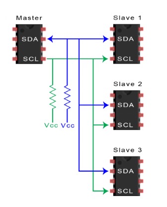
The I2C protocol works with a master-slave architecture (master-slave)
With this communication protocol it is possible to connect:
A master with several slaves:
and also allows multiple masters. And each master can interact with the slave without affecting the operation between them (between masters):
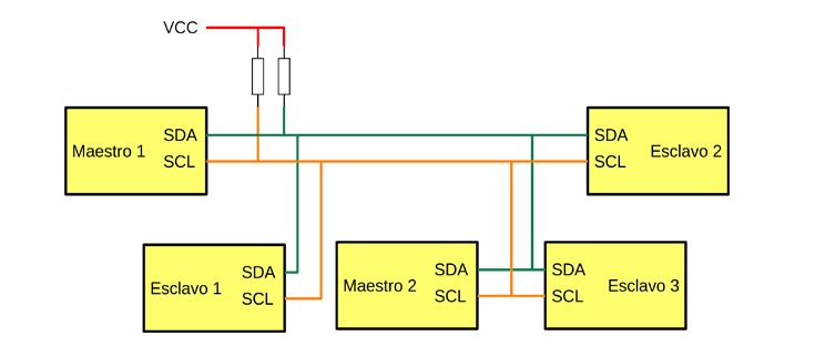
I find this very interesting for my final project. Because I just want to use two sensors that work at the same time but independently and even, although I don’t think I can do it for my final project, use two masters that are connected to the two sensors, in this case it would be the acceleration and gyroscope sensors.
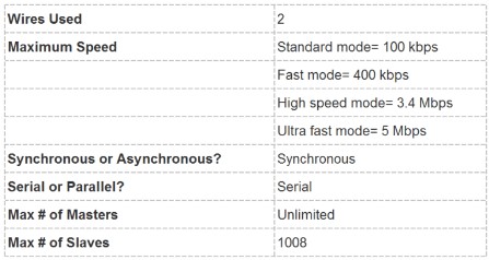
I searched literature about I2C and found a lot of information
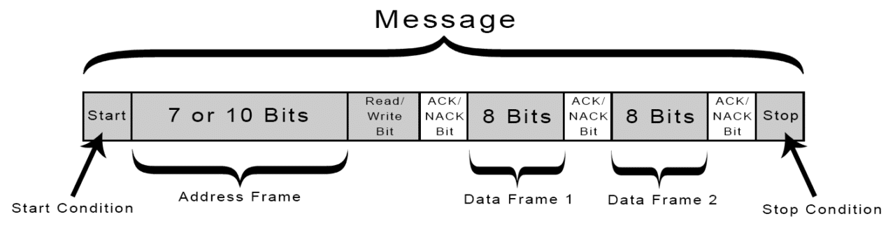
These are some illustrative images about I2C and the way it establishes communication between the Master and the Slave:
Communication between placa atMega 328 whith one and two sensor
As part of the final project I use the MPU6050 sensor (accelerometer / gyroscope) which uses the I2C protocol to communicate with the Atmega 328
I load a code for to read two sensor reading, getting a good result:
#include<Wire.h>
const int MPU2 = 0x69, MPU1 = 0x68;// OK
int16_t AcX1,AcY1,AcZ1,Tmp1,GyX1,GyY1,GyZ1;//OK
int16_t AcX2,AcY2,AcZ2,Tmp2,GyX2,GyY2,GyZ2;//OK


//-------------------------------------------------\setup loop\------------------------------------------------------------
 void setup(){
      Wire.begin();
      Wire.beginTransmission(MPU1);
      Wire.write(0x6B);// PWR_MGMT_1 register
      Wire.write(0); // set to zero (wakes up the MPU-6050)
      Wire.endTransmission(true);
      Wire.begin();
      Wire.beginTransmission(MPU2);
      Wire.write(0x6B);// PWR_MGMT_1 register
      Wire.write(0); // set to zero (wakes up the MPU-6050)
      Wire.endTransmission(true);
      Serial.begin(9600);
     }

//---------------------------------------------------\void loop\------------------------------------------------------------
 void loop(){

      //get values for first mpu having address of 0x68
      GetMpuValue1(MPU1);
      Serial.print("  ");
      Serial.print("|||");

      //get values for second mpu having address of 0x69
      GetMpuValue2(MPU2);
      Serial.println("");
    }

//----------------------------------------------\user defined functions\--------------------------------------------------


 void GetMpuValue1(const int MPU){

      Wire.beginTransmission(MPU);
      Wire.write(0x3B); // starting with register 0x3B (ACCEL_XOUT_H)
      Wire.endTransmission(false);
      Wire.requestFrom(MPU, 14, true); // request a total of 14 registers
      AcX1=Wire.read()<<8| Wire.read(); // 0x3B (ACCEL_XOUT_H) & 0x3C (ACCEL_XOUT_L)
      AcY1=Wire.read()<<8|  Wire.read(); // 0x3D (ACCEL_YOUT_H) & 0x3E (ACCEL_YOUT_L)
      AcZ1=Wire.read()<<8| Wire.read(); // 0x3F (ACCEL_ZOUT_H) & 0x40 (ACCEL_ZOUT_L)
      Tmp1=Wire.read()<<8| Wire.read(); // 0x41 (TEMP_OUT_H) & 0x42 (TEMP_OUT_L)
      GyX1=Wire.read()<<8| Wire.read(); // 0x43 (GYRO_XOUT_H) & 0x44 (GYRO_XOUT_L)
      GyY1=Wire.read()<<8| Wire.read(); // 0x45 (GYRO_YOUT_H) & 0x46 (GYRO_YOUT_L)
      GyZ1=Wire.read()<<8| Wire.read(); // 0x47 (GYRO_ZOUT_H) & 0x48 (GYRO_ZOUT_L)
      Serial.print("AcX = ");
      Serial.print(AcX1);
      Serial.print(" | AcY = ");
      Serial.print(AcY1);
      Serial.print(" | AcZ = ");
      Serial.print(AcZ1);
      Serial.print(" | GyX = ");
      Serial.print(GyX1);
      Serial.print(" | GyY = ");
      Serial.print(GyY1);
      Serial.print(" | GyZ = ");
      Serial.println(GyZ1);
     }


 void GetMpuValue2(const int MPU){

      Wire.beginTransmission(MPU);
      Wire.write(0x3B); // starting with register 0x3B (ACCEL_XOUT_H)
      Wire.endTransmission(false);
      Wire.requestFrom(MPU, 14, true); // request a total of 14 registers
      AcX2=Wire.read()<<8| Wire.read(); // 0x3B (ACCEL_XOUT_H) & 0x3C (ACCEL_XOUT_L)
      AcY2=Wire.read()<<8|  Wire.read(); // 0x3D (ACCEL_YOUT_H) & 0x3E (ACCEL_YOUT_L)
      AcZ2=Wire.read()<<8| Wire.read(); // 0x3F (ACCEL_ZOUT_H) & 0x40 (ACCEL_ZOUT_L)
      Tmp2=Wire.read()<<8| Wire.read(); // 0x41 (TEMP_OUT_H) & 0x42 (TEMP_OUT_L)
      GyX2=Wire.read()<<8| Wire.read(); // 0x43 (GYRO_XOUT_H) & 0x44 (GYRO_XOUT_L)
      GyY2=Wire.read()<<8| Wire.read(); // 0x45 (GYRO_YOUT_H) & 0x46 (GYRO_YOUT_L)
      GyZ2=Wire.read()<<8| Wire.read(); // 0x47 (GYRO_ZOUT_H) & 0x48 (GYRO_ZOUT_L)
      Serial.print("AcX = ");
      Serial.print(AcX2);
      Serial.print(" | AcY = ");
      Serial.print(AcY2);
      Serial.print(" | AcZ = ");
      Serial.print(AcZ2);
      Serial.print(" | GyX = ");
      Serial.print(GyX2);
      Serial.print(" | GyY = ");
      Serial.print(GyY2);
      Serial.print(" | GyZ = ");
      Serial.println(GyZ2);
     }
The idea was always to use two sensors as it is in the human being. For this reason I test the reading of two sensors by modifying the code based on several tutorials
I made several unsuccessful attempts, I only got a reading from one sensor.
I verified that the problem was not in the code, because I provided several.
I was able to discover based on tutorials that when using two MPU6050 sensors, the address must be modified and that is achieved by using the AD0 pin of the sensor.
Photo of part of the tutorial that enlightened me and after 3 hours of trying I got it to work:
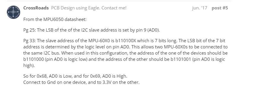
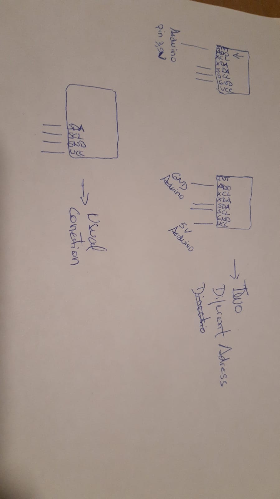
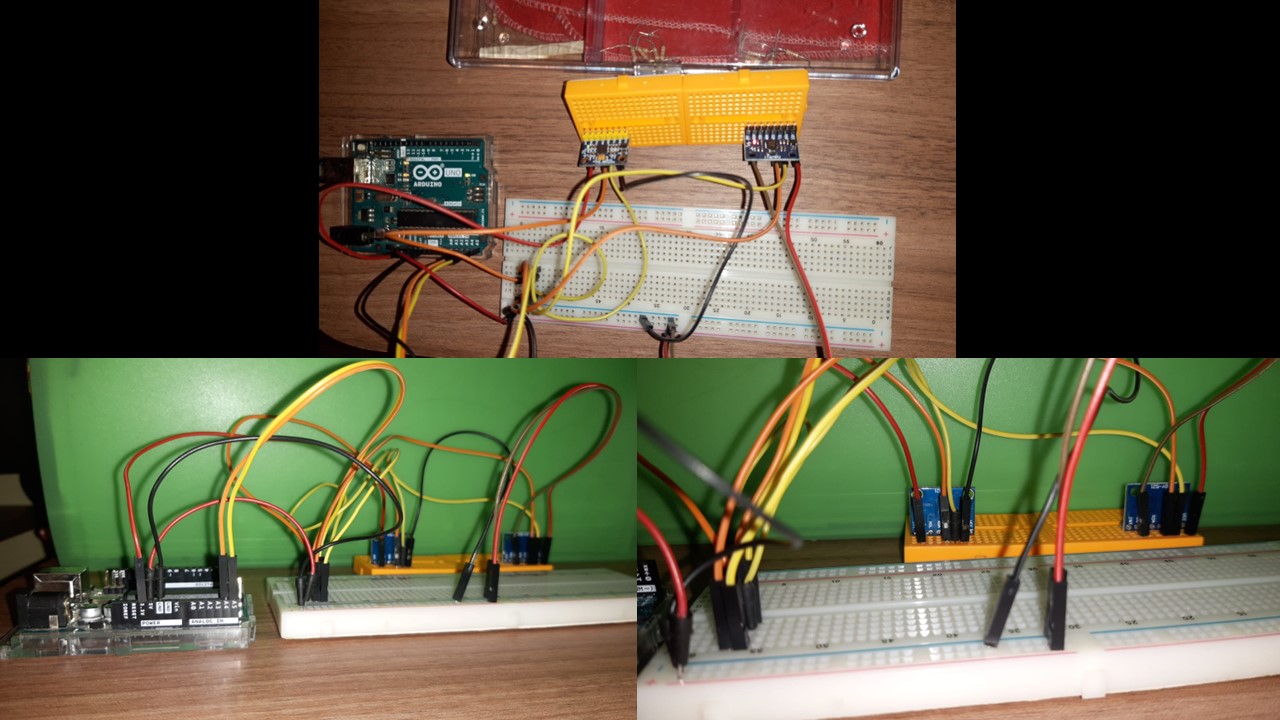
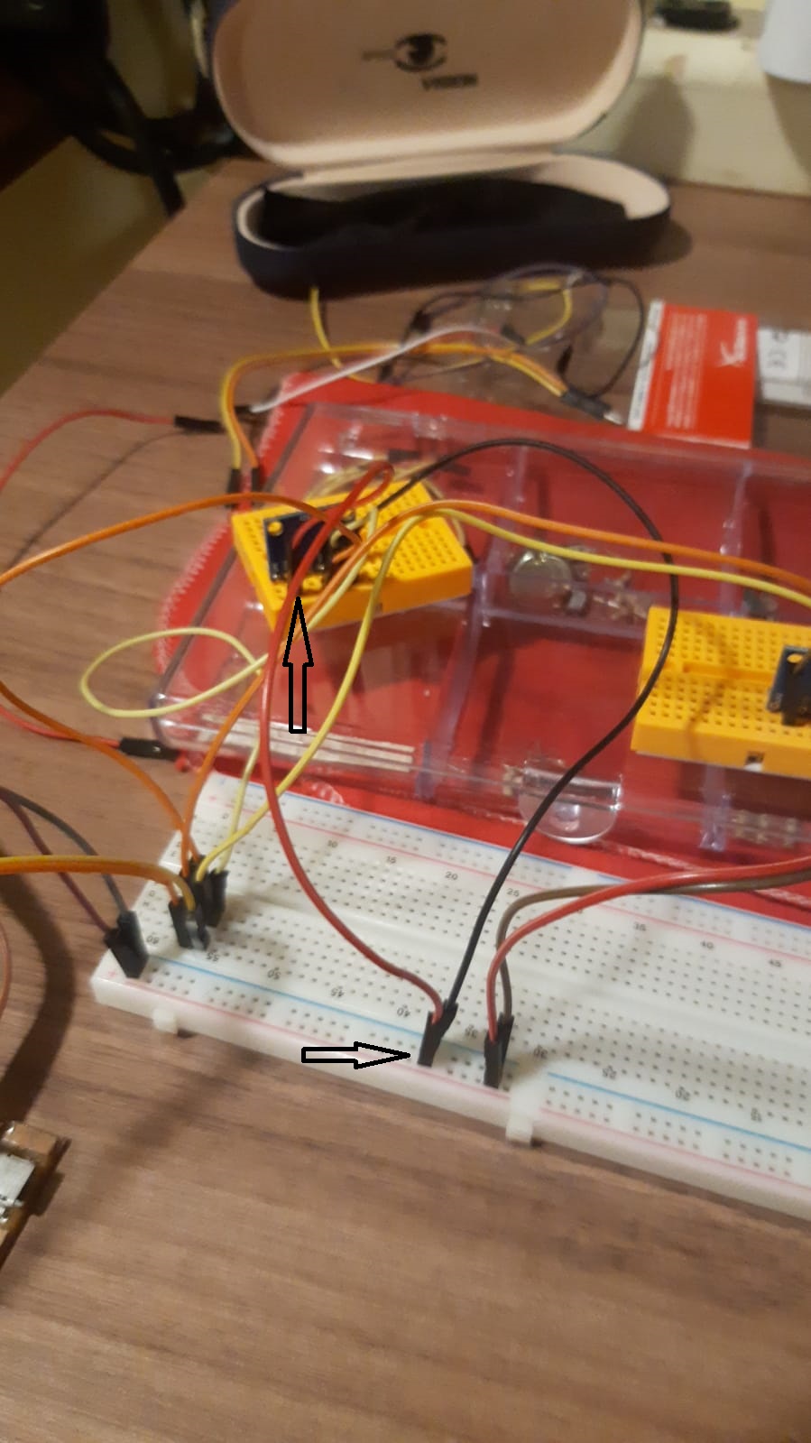
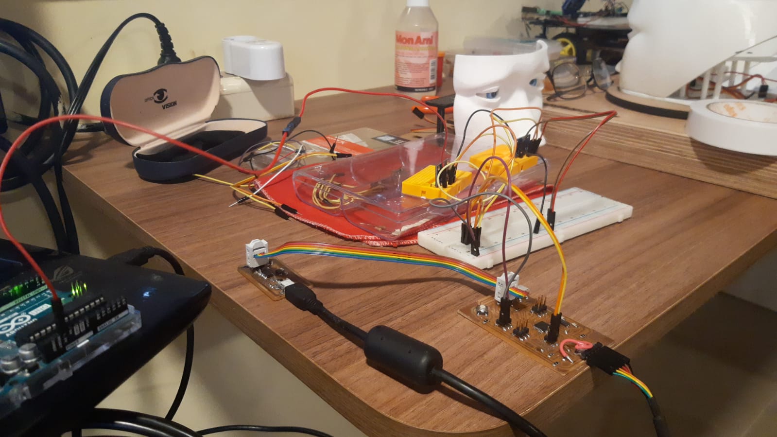
Photo of conections
Video
MPU6050 left
MPU6050_letf
MPU6050 rigth
MPU6050_rigth
I did the same test using the integrated circuit, connecting it to the two MPU6050 sensors, the files and the manufacture of said circuit can be seen in task 11 output device
Connection between the atmega 328 board and two MPU6050 sensor:
A problem arose, my integrated circuit does not have a 3.5 volt output. In any case, I tried connecting the two sensors with VCC 5Volt on the board and the result was negative, only one sensor was captured.
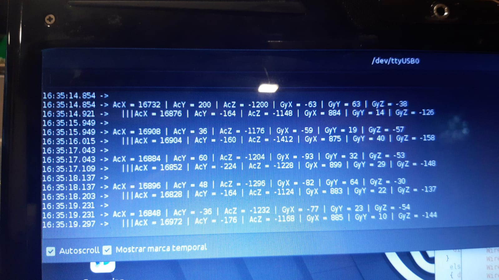
Failed result observed on serial monitor
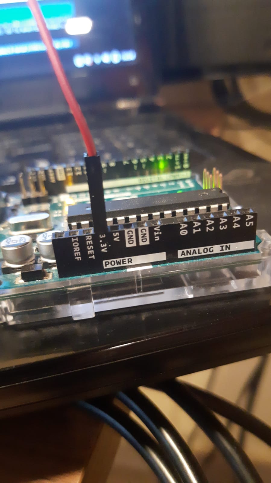
I used the 3.5 volt arduino uno power supply and that’s how it worked
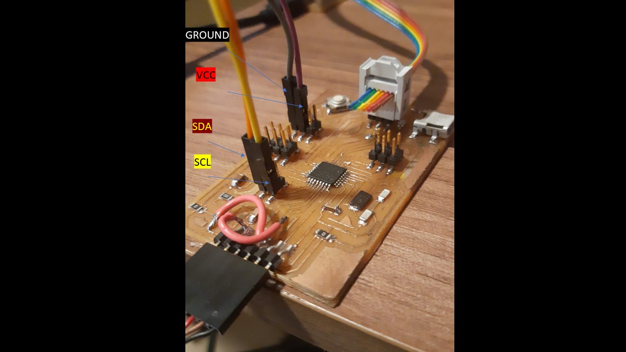
Photo showing the connection between the 3.5 volt of the arduino and the AD0 pin of the MPU6050
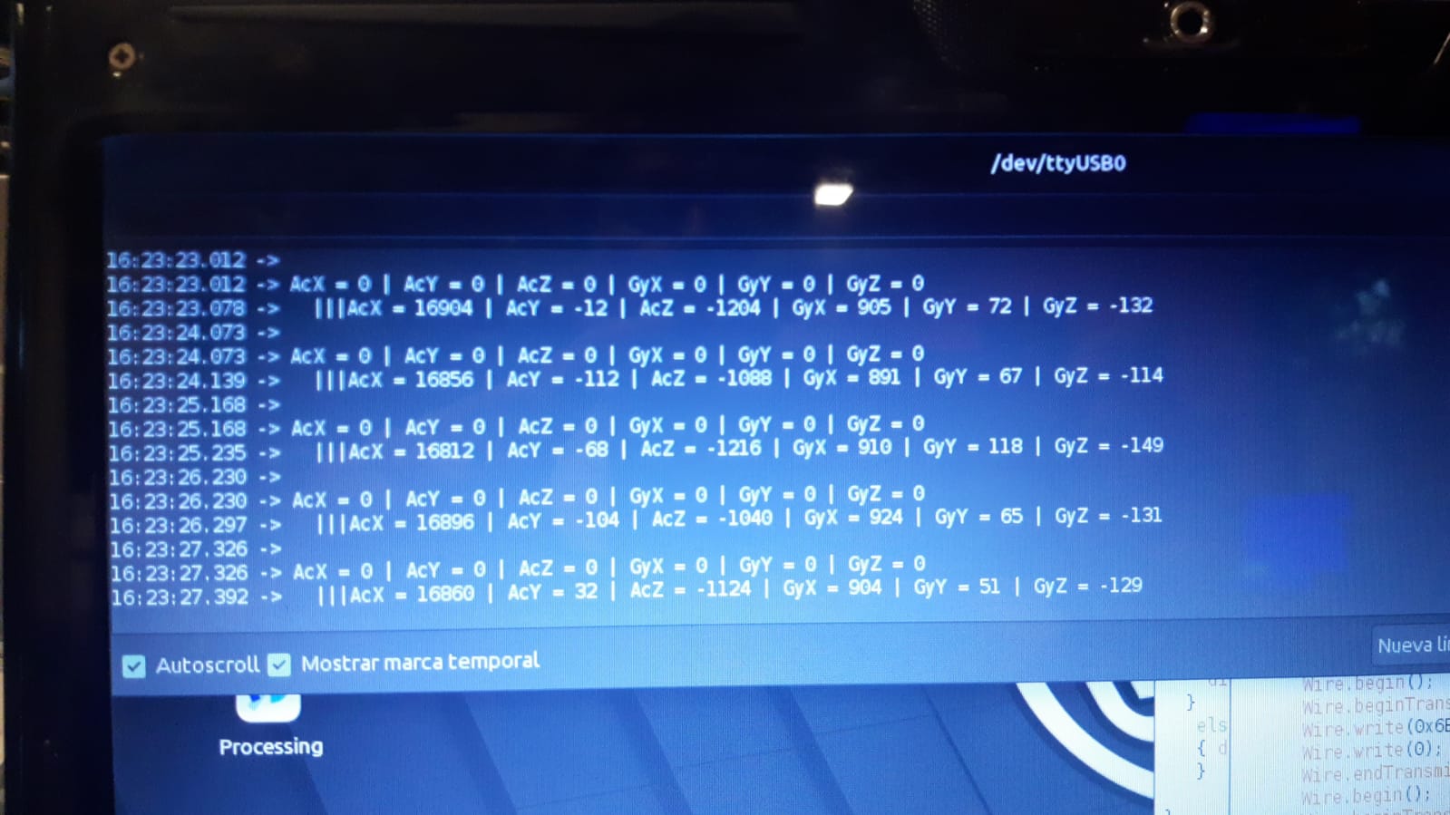
Correct result observed on serial monitor
Network connection between two PCBs
I will do it through the UART protocol
UART
UART, or universal asynchronous receiver-transmitter, is one of the most used device-to-device communication protocols.
The UART lines serve as the communication medium to transmit and receive one data to another. Take note that a UART device has a transmit and receive pin dedicated for either transmitting or receiving.
The UART interface does not use a clock signal to synchronize the transmitter and receiver devices; it transmits data asynchronously. Instead of a clock signal, the transmitter generates a bitstream based on its clock signal while the receiver is using its internal clock signal to sample the incoming data. The point of synchronization is managed by having the same baud rate on both devices
This one intresting link about UART
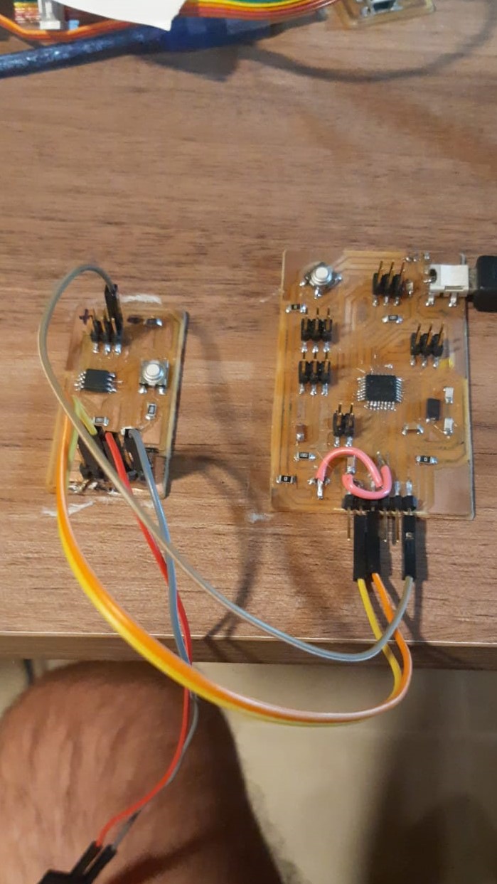
Network connection between two boards: the atMega328 and the attiny45 using UART protocol
I want to connect the atMega328 board with the attiny45 with built-in LED, both manufactured in previous tasks
As a first step I analyze the pins of each board to better define the connections
Photo Schematic PCB with LED and conection Rx PIN 1 y Tx PIN 2 attiny 45 (SLAVE)
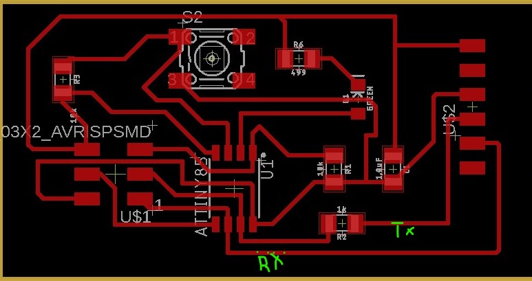
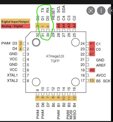
Photo pinout atMega Rx y Tx
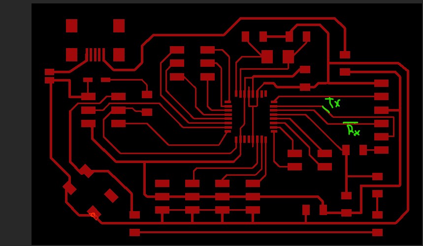
Pohto Schematic PCB atmega320 Rx y Tx
CODE 1 for atMega328 (master)
#define LED_PIN 13

void setup()
{
  Serial.begin(9600);
  pinMode(LED_PIN, OUTPUT);
}

void loop()
{
  int buttonState =  Serial.read();

  if (buttonState == '1') {
    digitalWrite(LED_PIN, HIGH);
  }
  else if (buttonState == '0') {
     digitalWrite(LED_PIN, LOW);
  }
  delay(100);
}
This video shows that by putting “1” in the Serial Monitor the LED of the atMega328 turns on and when putting “0” it turns off
CODE 2 for Attiny45 (eslave)
#include <SoftwareSerial.h>

int rx = 1;    //Declares the RX pin
int tx = 2;    //Declares the TX pin

SoftwareSerial mySerial(rx, tx);  //Setting up the RX/TX pins as a SoftwareSerial

char buttonState = '1';//Declares the character that represents the virtual button current state
char lastButtonState = '0'; //Declares the character that represents the virtual button last state

void setup(){
  mySerial.begin(9600);       //Start the serial communication and select the its speed that deppends of the frequency that it will be program the attiny
}

void loop() {

  buttonState = mySerial.read();    //Reads the message a "1" or a "0" from the command line

  if (buttonState != lastButtonState) {   //Checks if there exist a change in the virtual button state

    if (buttonState == '1') {         // Condition For Motor ON

      mySerial.println("1");         //Prints in the screen the actual state

    }
    else if (buttonState == '0'){      // Condition For Motor OFF

      mySerial.println("0");         //Prints in the screen the actual state

    }

    delay(50);
  }

  lastButtonState = buttonState;        //Sets the current state as a last state

}
FIRST CODE 2 (not working)
Il y a probablement un problème avec le code et je suis en train de chercher une solution.
SECOND CODE 2 (that works)
#include <SoftwareSerial.h>

int rx = 2;    //Declares the RX pin
int tx = 1;    //Declares the TX pin

SoftwareSerial mySerial(rx, tx);  //Setting up the RX/TX pins as a SoftwareSerial

char buttonState = '1';//Declares the character that represents the virtual button current state
char lastButtonState = '0'; //Declares the character that represents the virtual button last state

void setup(){
  mySerial.begin(9600);       //Start the serial communication and select the its speed that deppends of the frequency that it will be program the attiny
  pinMode(4, INPUT);           // set pin to input

}

void loop() {

  buttonState = digitalRead(4);    //Reads the message a "1" or a "0" from the command line

  // if (buttonState != lastButtonState) {   //Checks if there exist a change in the virtual button state

    if (buttonState == HIGH) {         // Condition For Motor ON

      mySerial.println("1");         //Prints in the screen the actual state

    }
    else if (buttonState == LOW){      // Condition For Motor OFF

      mySerial.println("0");         //Prints in the screen the actual state

    }

    delay(50);
//  }

  // lastButtonState = buttonState;        //Sets the current state as a last state

}
This video shows that pressing the button generates the value “1” in the Serial Monitor and when you stop pressing the value “0”
VIDEO attiny45 MonitorSerial comunication
In this way I already have it configured so that the two plates work together.
The idea is that pressing the attiny45 button turns on the atMega 328 LED
Photo showing the conections betwen atMega 328 and attiny45 UART protocol
References
1- https://programarfacil.com/blog/arduino-blog/comunicacion-i2c-con-arduino/
Today I learned
I learned what I2C communication is and how it works
That there are several communication protocols and to name two more: UART and ISP, with their advantages and disadvantages
Other things that I learned when reviewing
When comparing circuits with different microprocessors, I corroborated that there are fixed provisions regarding:
The Reset of the microprocessor: this is connected to the reset of the ISP and to the VCC, the latter interposing a 10 kohm resistor
The GND bridges the VCC with a 1uF capacitor although they differ in number (two capacitors for the Danduino).
The Crystal: it has two 10 pF capacitors and is connected to the GND and to the specific pins for the microprocessor crystal.