Final Project
Functional representation of the vestibulo-oculomotor reflex (VOR) through digital manufacturing
Research
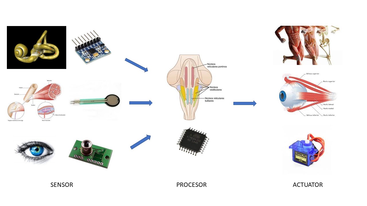
The vestibulo-ocular reflex is part of the balance system, the balance system is made up of three elements, using a language better known in electronic jargon:
a- the sensors
b- the processors
c- the actuators
The sensors: the ear, the eye, and the proprioceptors of muscles and tendons
The processors: the sensory nuclei and the motor nuclei at the level of the central nervous system
The actuators: the muscles and ligaments.
This image below shows the elements of the balance system with the corresponding electronic component
The balance is basically given by two reflex:
Vestibular-espinal reflex
The vestibulo-ocular reflex
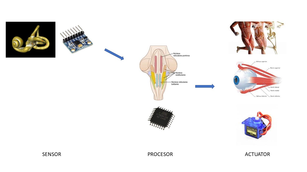
The final project focuses on the ocular vestibule reflex that is defined as:
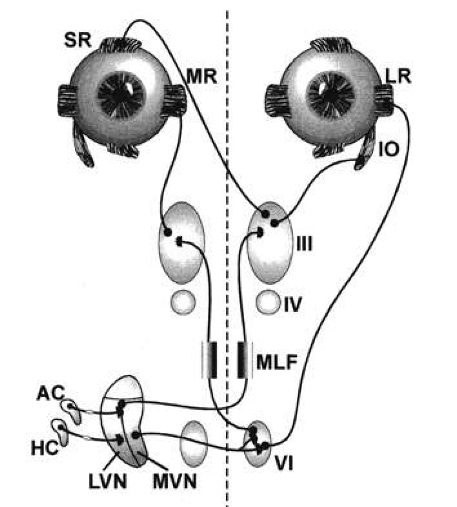
The vestibulo-ocular reflex (VOR) is a reflex acting to stabilize gaze during head movement, with eye movement due to activation of the vestibular system. The reflex acts to stabilize images on the retinas of the eye during head movement. Gaze is held steadily on a location by producing eye movements in the direction opposite that of head movement.
The components of the vestibulo-ocular reflex are:
The ears
nuclei located in the central nervous system
The muscles and ligaments of the eye
The image below shows the components of the vestibulo-oculomotor reflex.
For more details you can to see: Principles and practices
Objetive
With this project I intend to recreate the normal function of the vestibulo-ocular reflex approaching the anatomy and physiology of the human being and to obtain a model that can be used for a better understanding of the mechanism.
Project development
The first step was:
Compare the ear sensor with an existing electronic device.
Investigate about microprocessors, libraries and codes (our model was the Arduino Uno) and
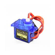
As an actuator, we initially think of servomotors
Sensor:
We must remember that the ear, in its participation in balance, detects movement and gravity. The angular accelerations are given by the semicircular canals and the linear accelerations by the utricle and saccule.
Reference on planes or axes of the ear and the terms roll, yaw and pitch
The electronic device that seemed similar to the ear was the MPU6050.
Image below illustrating the three axes (Roll, Pitch and Yaw) captured by the MPU6050 and the ear
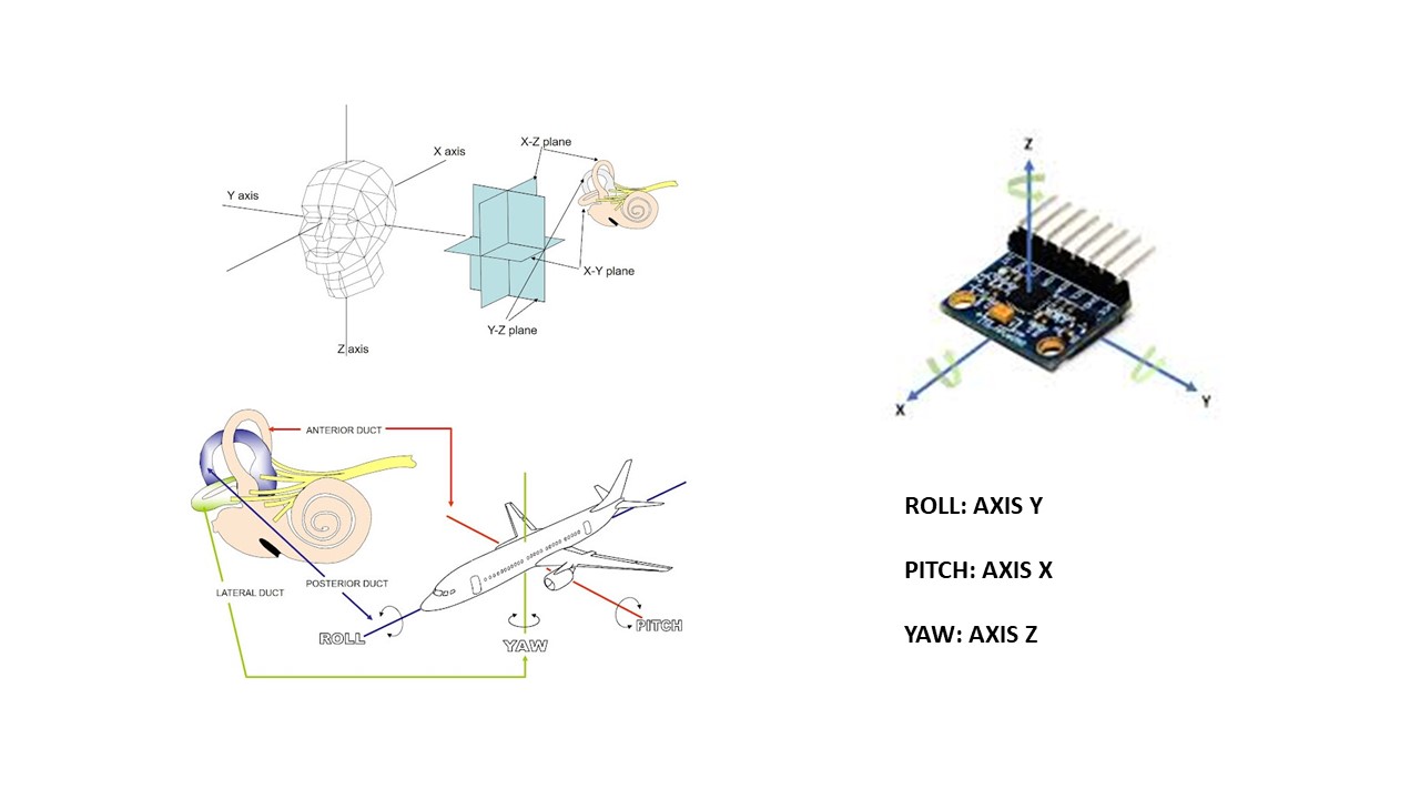
For angular movements:
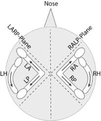
The ear has three semicircular canals oriented in the three planes: superior, posterior and lateral semicircular canal. The superior and posterior canals are oriented in the vertical plane and at an angle of 90 degrees to each other, open outwards, and the lateral semicircular canal is oriented almost in the horizontal plane. Remembering that exactly the same anatomy is repeated on the contralateral side but in the opposite direction. Physiologically, they work in synchrony: the upper right with the rear left, the upper left with the rear right, and the sides in the same horizontal plane. (Ilustred below). In this way, when the head turns in any of the planes, one of them is always stimulated and the other is inhibited.
LARP-plane: Left Anterior Right Posterior
RALP-plane: Right Anterior Left Posterior
RH: Right horizontal
LH: Left horizontal
Observation: Anterior = Superior
For linear movements:
The ear has two sensors: the utricle and the saccule, which are also located in the horizontal and vertical planes, respectively. These contain some “pebbles” or otoconia on their surface that, through a mechanism of inertia, cause an alteration of the surface, stimulating or inhibiting the sensory cells on which they rest.
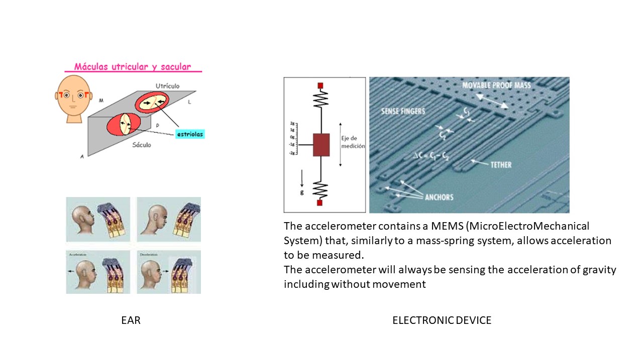
I was struck by the similarity with the spring mass mechanism of the MPU6050 sensor. Both use a mass that in the case of the ear would be the otoconia and the gel that surrounds them would be like the springs. (See image above)
Referencia for sensor MPU6050 caracteristic
Microprocesor:
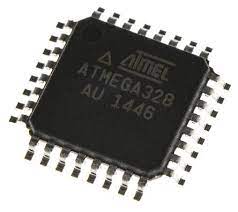
Our model device is the Arduino Uno. The new board will use the AtMega 328 which is the same as the Arduino uno.
actuator
The sg90 servomotor is chosen because it is economical and effective for what we want to demonstrate or illustrate, which is the movement of the eyes in a single plane, the horizontal, in response to the MPU6050 sensor.
The following steps were carried out in parallel following the program of the FABLAB course. For reasons of order, I choose to start with the first diagrams of the 2D and 3D design process and then expose the part of the electronic design and creation process and programming.
2D and 3D Modeling Process
Image below illustrating the original idea: two sensor MPU6050 in both sides, the microprocesor in the midle and two servomotors in the front
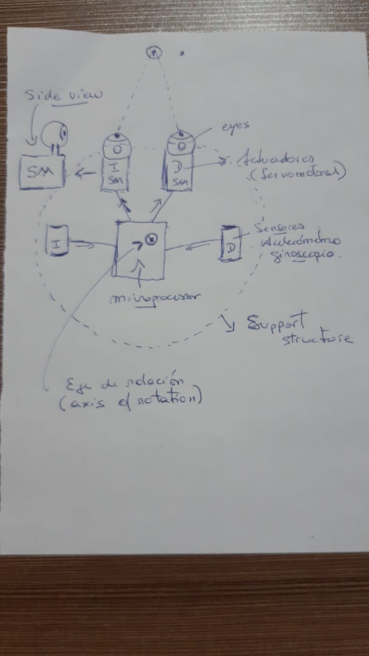
Image below illustrating the 3D modeling in tinkerkad
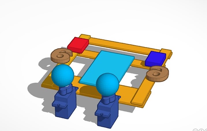
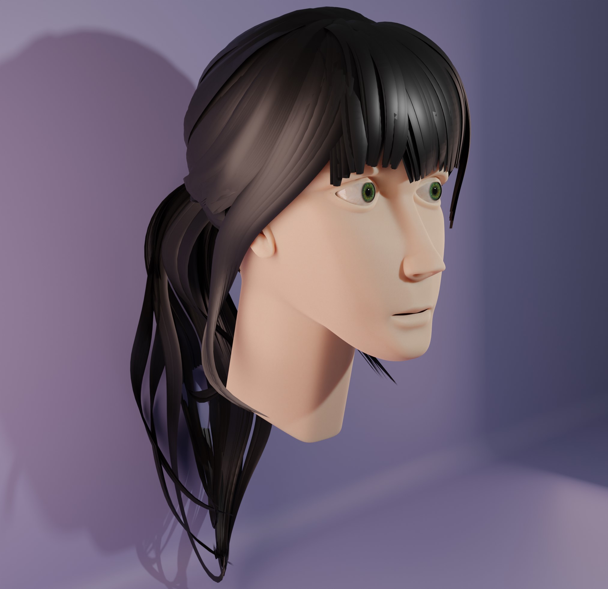
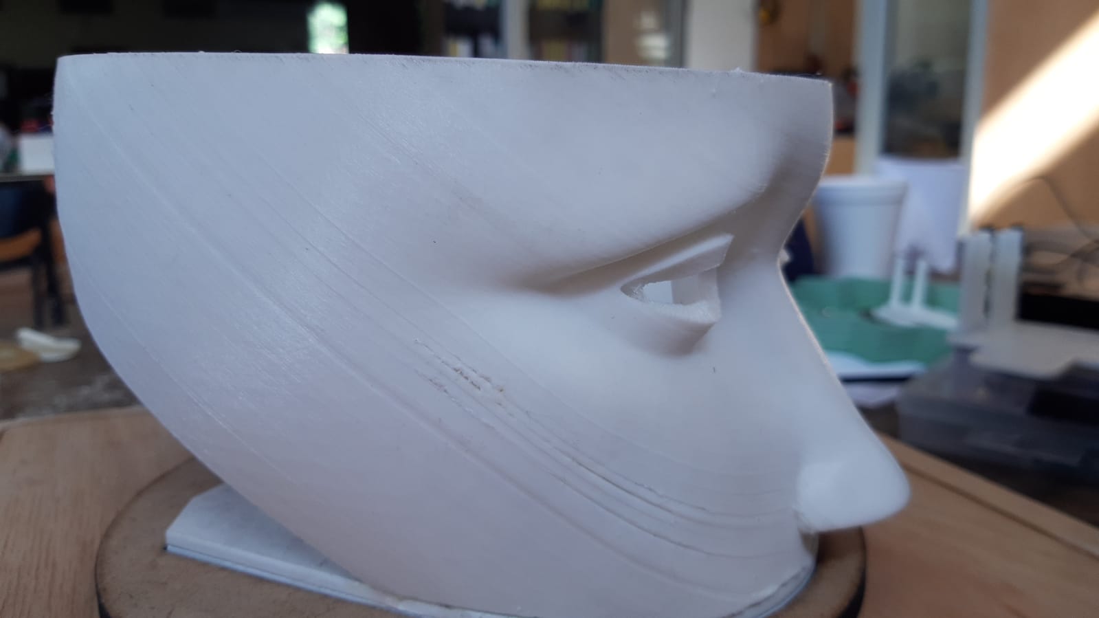
Image below illustrating head modeling whit Blender software
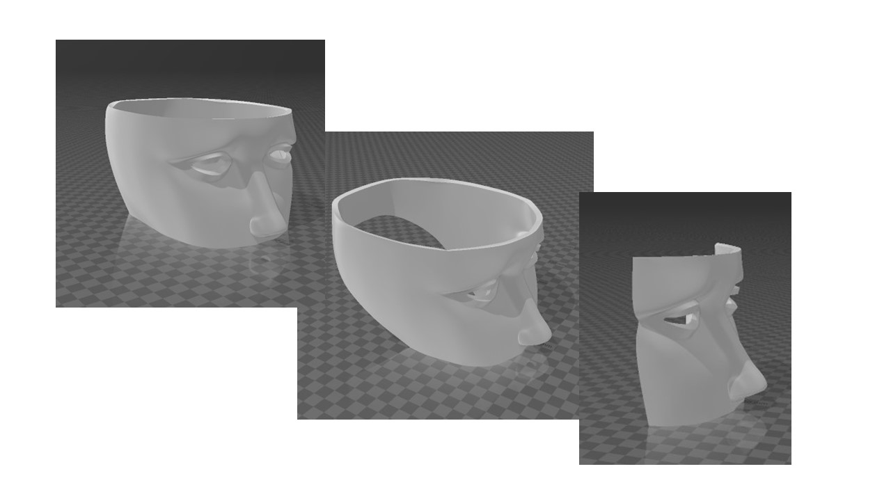
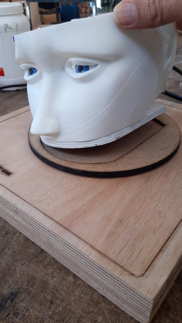
We decided to use part of the head that obviously includes the opening of the eyes and the nose. First we decided to print on the face so that the supports don’t mess up the quality of the print, but later we did another full print, but cut as shown in the photo above so that the face is facing up during printing and also in this way we obtain rear and upper space to place the electronic components
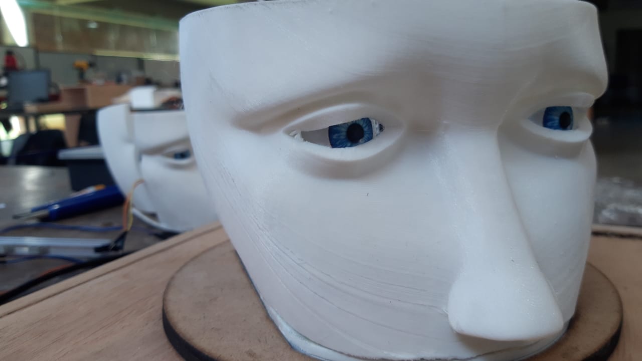
3D printin result
File: Face_Designe
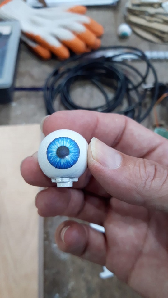
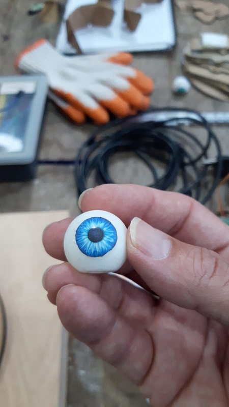
The eyes
The eyes were designed in blender and then exported in stl format for 3D printing. We use two types of printers: LCD with resin and PLA plus, both with good results.
For the iris and the pupil we use adhesive paper
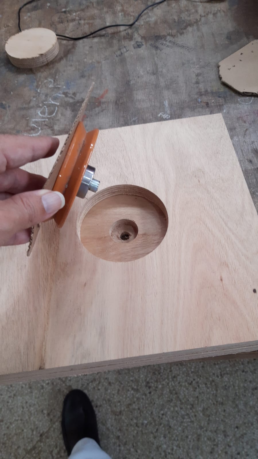
We glue the servo adapter itself to the base of the eye
The Files you can trouve in Week 6
The platform for internal components:
Firs I wrote on paper the steps to follow and the elements to use to order the thought
I made a design on paper and then on cardboard to have greater accuracy of where to place each component and the relationship of each of them is size, height, etc.
This way of working helped me a lot to center or focus my ideas
Finally, using the fusion 360 program, I design the platform.
Photo below with the assembly steps
In paper and cardboard
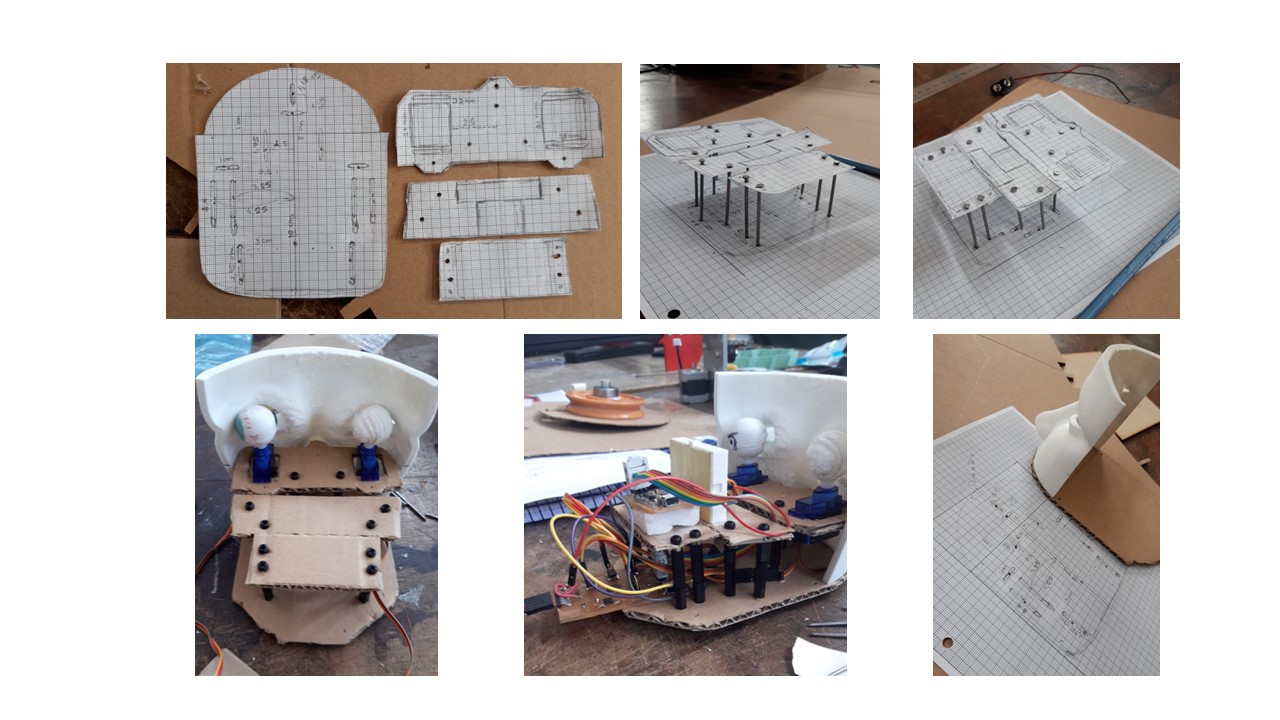
Laser cut
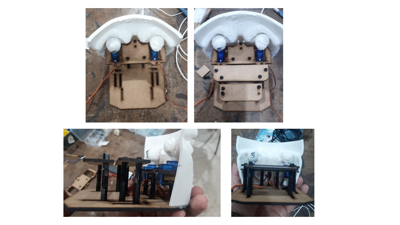
The upper platform we decided to make it with 3D printing. We included in the design the columns, which would be fixed with screws in the lower platform.
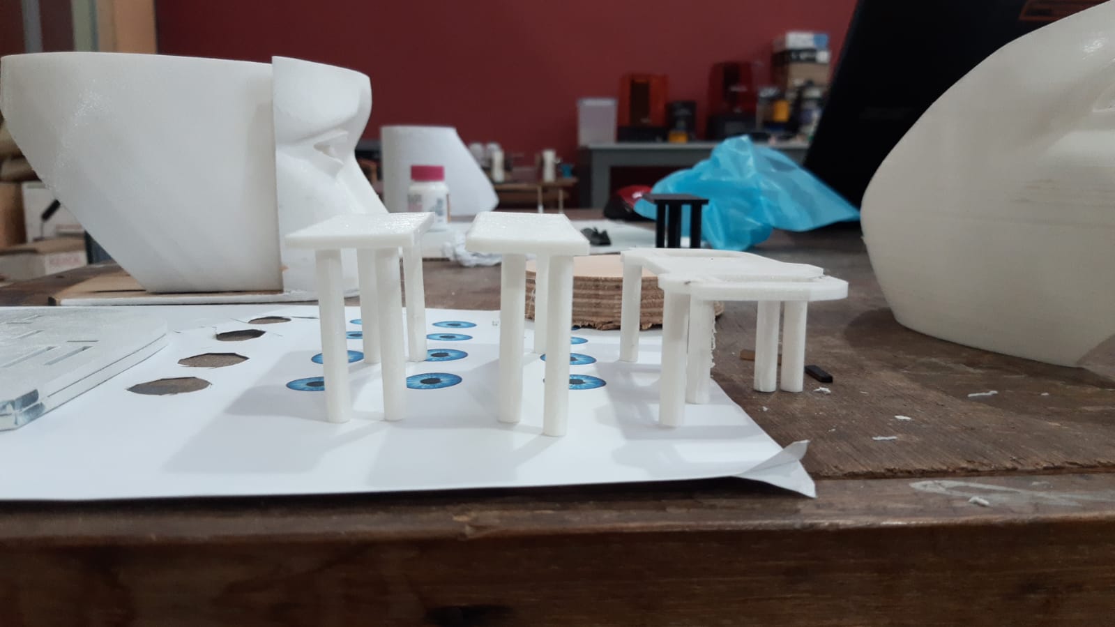
The laser cut lower platform is painted white
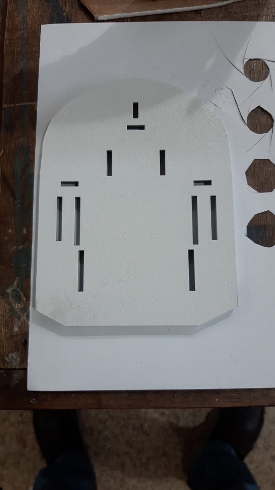
Since the screws on the underside of the bottom deck were protruding, I cut another one the same size but with larger internal holes, thus achieving a smooth bottom surface.
The rotating base
Third step: electronic production and design
Librery and Codes
Using the Arduino uno or the nano, we look for libraries for the use of the sensor and codes that manage to read the information that they capture:
The first attempts to capture information from the MPU6050 sensors were made during the week input device
With the first codes I can’t get exact information. I needed the value of the offset angle on the Z axis
Of all the codes that we look for we liked this:
This tutorial for use MPU6050 like gimbal it was vary usefull for me.
Wire code for MPU6050:
/*
   Arduino and MPU6050 Accelerometer and Gyroscope Sensor Tutorial
   by Dejan, https://howtomechatronics.com
*/

#include <Wire.h>
const int MPU = 0x68; // MPU6050 I2C address
float AccX, AccY, AccZ;
float GyroX, GyroY, GyroZ;
float accAngleX, accAngleY, gyroAngleX, gyroAngleY, gyroAngleZ;
float roll, pitch, yaw;
float AccErrorX, AccErrorY, GyroErrorX, GyroErrorY, GyroErrorZ;
float elapsedTime, currentTime, previousTime;
int c = 0;
void setup() {
  Serial.begin(19200);
  Wire.begin();                      // Initialize comunication
  Wire.beginTransmission(MPU);       // Start communication with MPU6050 // MPU=0x68
  Wire.write(0x6B);                  // Talk to the register 6B
  Wire.write(0x00);                  // Make reset - place a 0 into the 6B register
  Wire.endTransmission(true);        //end the transmission
  /*
  // Configure Accelerometer Sensitivity - Full Scale Range (default +/- 2g)
  Wire.beginTransmission(MPU);
  Wire.write(0x1C);                  //Talk to the ACCEL_CONFIG register (1C hex)
  Wire.write(0x10);                  //Set the register bits as 00010000 (+/- 8g full scale range)
  Wire.endTransmission(true);
  // Configure Gyro Sensitivity - Full Scale Range (default +/- 250deg/s)
  Wire.beginTransmission(MPU);
  Wire.write(0x1B);                   // Talk to the GYRO_CONFIG register (1B hex)
  Wire.write(0x10);                   // Set the register bits as 00010000 (1000deg/s full scale)
  Wire.endTransmission(true);
  delay(20);
  */
  // Call this function if you need to get the IMU error values for your module
  calculate_IMU_error();
  delay(20);
}
void loop() {
  // === Read acceleromter data === //
  Wire.beginTransmission(MPU);
  Wire.write(0x3B); // Start with register 0x3B (ACCEL_XOUT_H)
  Wire.endTransmission(false);
  Wire.requestFrom(MPU, 6, true); // Read 6 registers total, each axis value is stored in 2 registers
  //For a range of +-2g, we need to divide the raw values by 16384, according to the datasheet
  AccX = (Wire.read() << 8 | Wire.read()) / 16384.0; // X-axis value
  AccY = (Wire.read() << 8 | Wire.read()) / 16384.0; // Y-axis value
  AccZ = (Wire.read() << 8 | Wire.read()) / 16384.0; // Z-axis value
  // Calculating Roll and Pitch from the accelerometer data
  accAngleX = (atan(AccY / sqrt(pow(AccX, 2) + pow(AccZ, 2))) * 180 / PI) - 0.58; // AccErrorX ~(0.58) See the calculate_IMU_error()custom function for more details
  accAngleY = (atan(-1 * AccX / sqrt(pow(AccY, 2) + pow(AccZ, 2))) * 180 / PI) + 1.58; // AccErrorY ~(-1.58)
  // === Read gyroscope data === //
  previousTime = currentTime;        // Previous time is stored before the actual time read
  currentTime = millis();            // Current time actual time read
  elapsedTime = (currentTime - previousTime) / 1000; // Divide by 1000 to get seconds
  Wire.beginTransmission(MPU);
  Wire.write(0x43); // Gyro data first register address 0x43
  Wire.endTransmission(false);
  Wire.requestFrom(MPU, 6, true); // Read 4 registers total, each axis value is stored in 2 registers
  GyroX = (Wire.read() << 8 | Wire.read()) / 131.0; // For a 250deg/s range we have to divide first the raw value by 131.0, according to the datasheet
  GyroY = (Wire.read() << 8 | Wire.read()) / 131.0;
  GyroZ = (Wire.read() << 8 | Wire.read()) / 131.0;
  // Correct the outputs with the calculated error values
  GyroX = GyroX + 0.56; // GyroErrorX ~(-0.56)
  GyroY = GyroY - 2; // GyroErrorY ~(2)
  GyroZ = GyroZ + 0.79; // GyroErrorZ ~ (-0.8)
  // Currently the raw values are in degrees per seconds, deg/s, so we need to multiply by sendonds (s) to get the angle in degrees
  gyroAngleX = gyroAngleX + GyroX * elapsedTime; // deg/s * s = deg
  gyroAngleY = gyroAngleY + GyroY * elapsedTime;
  yaw =  yaw + GyroZ * elapsedTime;
  // Complementary filter - combine acceleromter and gyro angle values
  roll = 0.96 * gyroAngleX + 0.04 * accAngleX;
  pitch = 0.96 * gyroAngleY + 0.04 * accAngleY;

  // Print the values on the serial monitor
  Serial.print(roll);
  Serial.print("/");
  Serial.print(pitch);
  Serial.print("/");
  Serial.println(yaw);
}
void calculate_IMU_error() {
  // We can call this funtion in the setup section to calculate the accelerometer and gyro data error. From here we will get the error values used in the above equations printed on the Serial Monitor.
  // Note that we should place the IMU flat in order to get the proper values, so that we then can the correct values
  // Read accelerometer values 200 times
  while (c < 200) {
    Wire.beginTransmission(MPU);
    Wire.write(0x3B);
    Wire.endTransmission(false);
    Wire.requestFrom(MPU, 6, true);
    AccX = (Wire.read() << 8 | Wire.read()) / 16384.0 ;
    AccY = (Wire.read() << 8 | Wire.read()) / 16384.0 ;
    AccZ = (Wire.read() << 8 | Wire.read()) / 16384.0 ;
    // Sum all readings
    AccErrorX = AccErrorX + ((atan((AccY) / sqrt(pow((AccX), 2) + pow((AccZ), 2))) * 180 / PI));
    AccErrorY = AccErrorY + ((atan(-1 * (AccX) / sqrt(pow((AccY), 2) + pow((AccZ), 2))) * 180 / PI));
    c++;
  }
  //Divide the sum by 200 to get the error value
  AccErrorX = AccErrorX / 200;
  AccErrorY = AccErrorY / 200;
  c = 0;
  // Read gyro values 200 times
  while (c < 200) {
    Wire.beginTransmission(MPU);
    Wire.write(0x43);
    Wire.endTransmission(false);
    Wire.requestFrom(MPU, 6, true);
    GyroX = Wire.read() << 8 | Wire.read();
    GyroY = Wire.read() << 8 | Wire.read();
    GyroZ = Wire.read() << 8 | Wire.read();
    // Sum all readings
    GyroErrorX = GyroErrorX + (GyroX / 131.0);
    GyroErrorY = GyroErrorY + (GyroY / 131.0);
    GyroErrorZ = GyroErrorZ + (GyroZ / 131.0);
    c++;
  }
  //Divide the sum by 200 to get the error value
  GyroErrorX = GyroErrorX / 200;
  GyroErrorY = GyroErrorY / 200;
  GyroErrorZ = GyroErrorZ / 200;
  // Print the error values on the Serial Monitor
  Serial.print("AccErrorX: ");
  Serial.println(AccErrorX);
  Serial.print("AccErrorY: ");
  Serial.println(AccErrorY);
  Serial.print("GyroErrorX: ");
  Serial.println(GyroErrorX);
  Serial.print("GyroErrorY: ");
  Serial.println(GyroErrorY);
  Serial.print("GyroErrorZ: ");
  Serial.println(GyroErrorZ);
}
Once the sensor test is done, we look for codes to move the servo
Time to be honest, sorry ! Since I lost part of my documentation, I cannot illustrate all the misfortunes that occurred. And since I don’t remember where I got the code to control the servo, but I do remember that Abdon used that code and introduced it to the sensor code.
To get the code of the servo I did a reverse engineering, I extracted it from the CODE of the sensor where I had included the servo and I got this code
This is the code I extracted from the sensor code related to servo control.
Photo of of CODE incorporated
I’m sorry, I’m sorry and I’m sorry again. I didn’t want to leave this hole in my documentation. I made a new documentation and thanks to that some things were clarified, I reviewed others and new cumbersome situations appeared, but well I think this is something usual (errors and successes)
If you take some time and visit my week 11 and week 13 (Output and Input device) I have updated my documentation and documented new experiences with the servos and the sensor. As a catharsis I tell you that I burned one of my sensors by connecting the GND and VCC backwards. (things that happen the instructors tell me)
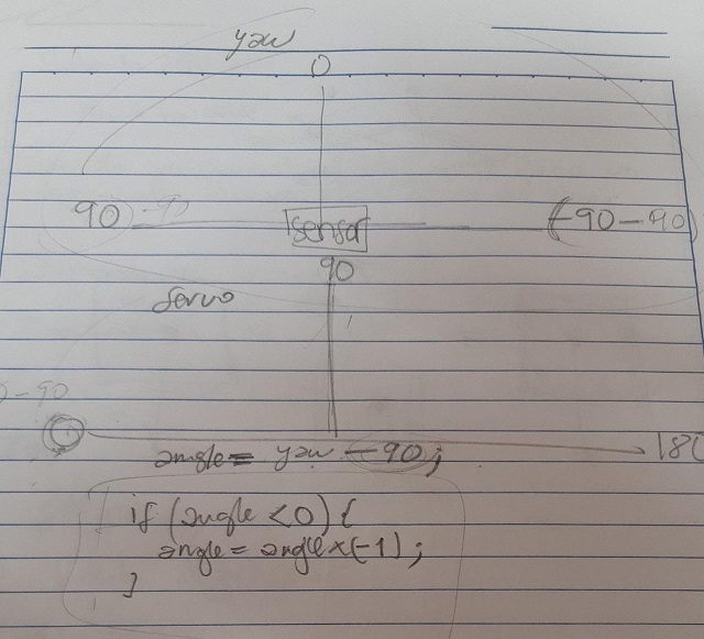
And we incorporate it into the sensor code making some adjustments so that the servomotor performs the inverse movement to the angle of rotation of the sensor.
We made with Abdon a reasoning on paper and then write the code. We needed the servo to perform exactly the inverse movement to the angle of rotation of the sensor
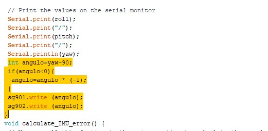
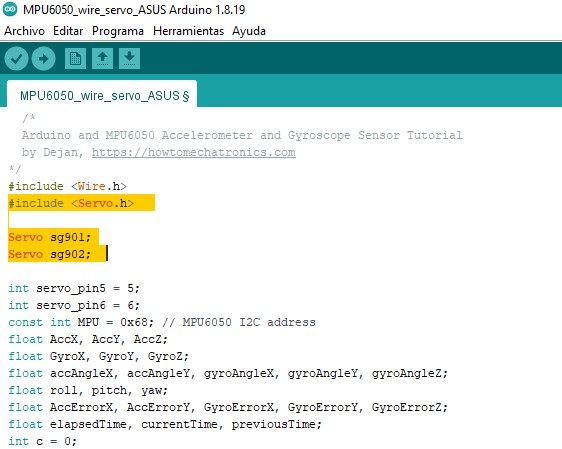
Code incorpored to Code MPU 6050
#include <Wire.h>
#include <Servo.h>
Servo sg901;
Servo sg902;
int servo_pin5 = 5;
int servo_pin6 = 6;
const int MPU = 0x68; // MPU6050 I2C address
float AccX, AccY, AccZ;
float GyroX, GyroY, GyroZ;
float accAngleX, accAngleY, gyroAngleX, gyroAngleY, gyroAngleZ;
float roll, pitch, yaw;
float AccErrorX, AccErrorY, GyroErrorX, GyroErrorY, GyroErrorZ;
float elapsedTime, currentTime, previousTime;
int c = 0;
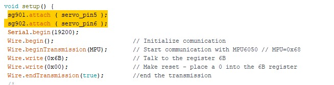
void setup() {
sg901.attach ( servo_pin5 );
sg902.attach ( servo_pin6 );
Serial.begin(19200);
Wire.begin(); // Initialize comunication
Wire.beginTransmission(MPU); // Start communication with MPU6050 // MPU=0x68
Wire.write(0x6B); // Talk to the register 6B
Wire.write(0x00); // Make reset - place a 0 into the 6B register
Wire.endTransmission(true); //end the transmission
/*
// Configure Accelerometer Sensitivity - Full Scale Range (default +/- 2g)
Wire.beginTransmission(MPU);
Wire.write(0x1C); //Talk to the ACCEL_CONFIG register (1C hex)
Wire.write(0x10); //Set the register bits as 00010000 (+/- 8g full scale range)
Wire.endTransmission(true);
// Configure Gyro Sensitivity - Full Scale Range (default +/- 250deg/s)
Wire.beginTransmission(MPU);
Wire.write(0x1B); // Talk to the GYRO_CONFIG register (1B hex)
Wire.write(0x10); // Set the register bits as 00010000 (1000deg/s full scale)
Wire.endTransmission(true);
delay(20);
*/
// Call this function if you need to get the IMU error values for your module
calculate_IMU_error();
delay(20);
}
void loop() {
// === Read acceleromter data === //
Wire.beginTransmission(MPU);
Wire.write(0x3B); // Start with register 0x3B (ACCEL_XOUT_H)
Wire.endTransmission(false);
Wire.requestFrom(MPU, 6, true); // Read 6 registers total, each axis value is stored in 2 registers
//For a range of +-2g, we need to divide the raw values by 16384, according to the datasheet
AccX = (Wire.read() << 8 | Wire.read()) / 16384.0; // X-axis value
AccY = (Wire.read() << 8 | Wire.read()) / 16384.0; // Y-axis value
AccZ = (Wire.read() << 8 | Wire.read()) / 16384.0; // Z-axis value
// Calculating Roll and Pitch from the accelerometer data
accAngleX = (atan(AccY / sqrt(pow(AccX, 2) + pow(AccZ, 2))) * 180 / PI) - AccErrorX ; // AccErrorX ~(0.58) See the calculate_IMU_error()custom function for more details
accAngleY = (atan(-1 * AccX / sqrt(pow(AccY, 2) + pow(AccZ, 2))) * 180 / PI) - AccErrorY ; // AccErrorY ~(-1.58)
// === Read gyroscope data === //
previousTime = currentTime; // Previous time is stored before the actual time read
currentTime = millis(); // Current time actual time read
elapsedTime = (currentTime - previousTime) / 1000; // Divide by 1000 to get seconds
Wire.beginTransmission(MPU);
Wire.write(0x43); // Gyro data first register address 0x43
Wire.endTransmission(false);
Wire.requestFrom(MPU, 6, true); // Read 4 registers total, each axis value is stored in 2 registers
GyroX = (Wire.read() << 8 | Wire.read()) / 131.0; // For a 250deg/s range we have to divide first the raw value by 131.0, according to the datasheet
GyroY = (Wire.read() << 8 | Wire.read()) / 131.0;
GyroZ = (Wire.read() << 8 | Wire.read()) / 131.0;
// Correct the outputs with the calculated error values
GyroX = GyroX - GyroErrorX ; // GyroErrorX ~(-0.56)
GyroY = GyroY - GyroErrorY ; // GyroErrorY ~(2)
GyroZ = GyroZ - GyroErrorZ ; // GyroErrorZ ~ (-0.8)
// Currently the raw values are in degrees per seconds, deg/s, so we need to multiply by sendonds (s) to get the angle in degrees
gyroAngleX = gyroAngleX + GyroX * elapsedTime; // deg/s * s = deg
gyroAngleY = gyroAngleY + GyroY * elapsedTime;
yaw = yaw + GyroZ * elapsedTime;
// Complementary filter - combine acceleromter and gyro angle values
roll = 0.96 * gyroAngleX + 0.04 * accAngleX;
pitch = 0.96 * gyroAngleY + 0.04 * accAngleY;
// Print the values on the serial monitor
Serial.print(roll);
Serial.print("/");
Serial.print(pitch);
Serial.print("/");
Serial.println(yaw);
int angulo=yaw-90;
if(angulo<0){
angulo=angulo * (-1);
}
sg901.write (angulo);
sg902.write (angulo);
}
void calculate_IMU_error() {
// We can call this funtion in the setup section to calculate the accelerometer and gyro data error. From here we will get the error values used in the above equations printed on the Serial Monitor.
// Note that we should place the IMU flat in order to get the proper values, so that we then can the correct values
// Read accelerometer values 200 times
while (c < 200) {
Wire.beginTransmission(MPU);
Wire.write(0x3B);
Wire.endTransmission(false);
Wire.requestFrom(MPU, 6, true);
AccX = (Wire.read() << 8 | Wire.read()) / 16384.0 ;
AccY = (Wire.read() << 8 | Wire.read()) / 16384.0 ;
AccZ = (Wire.read() << 8 | Wire.read()) / 16384.0 ;
// Sum all readings
AccErrorX = AccErrorX + ((atan((AccY) / sqrt(pow((AccX), 2) + pow((AccZ), 2))) * 180 / PI));
AccErrorY = AccErrorY + ((atan(-1 * (AccX) / sqrt(pow((AccY), 2) + pow((AccZ), 2))) * 180 / PI));
c++;
}
//Divide the sum by 200 to get the error value
AccErrorX = AccErrorX / 200;
AccErrorY = AccErrorY / 200;
c = 0;
// Read gyro values 200 times
while (c < 200) {
Wire.beginTransmission(MPU);
Wire.write(0x43);
Wire.endTransmission(false);
Wire.requestFrom(MPU, 6, true);
GyroX = Wire.read() << 8 | Wire.read();
GyroY = Wire.read() << 8 | Wire.read();
GyroZ = Wire.read() << 8 | Wire.read();
// Sum all readings
GyroErrorX = GyroErrorX + (GyroX / 131.0);
GyroErrorY = GyroErrorY + (GyroY / 131.0);
GyroErrorZ = GyroErrorZ + (GyroZ / 131.0);
c++;
}
//Divide the sum by 200 to get the error value
GyroErrorX = GyroErrorX / 200;
GyroErrorY = GyroErrorY / 200;
GyroErrorZ = GyroErrorZ / 200;
// Print the error values on the Serial Monitor
Serial.print("AccErrorX: ");
Serial.println(AccErrorX);
Serial.print("AccErrorY: ");
Serial.println(AccErrorY);
Serial.print("GyroErrorX: ");
Serial.println(GyroErrorX);
Serial.print("GyroErrorY: ");
Serial.println(GyroErrorY);
Serial.print("GyroErrorZ: ");
Serial.println(GyroErrorZ);
}
Video showing the mechanism that we want the servomotor to perform based on the angle of rotation of the sensor on a provisional platform mounted on cardboard.
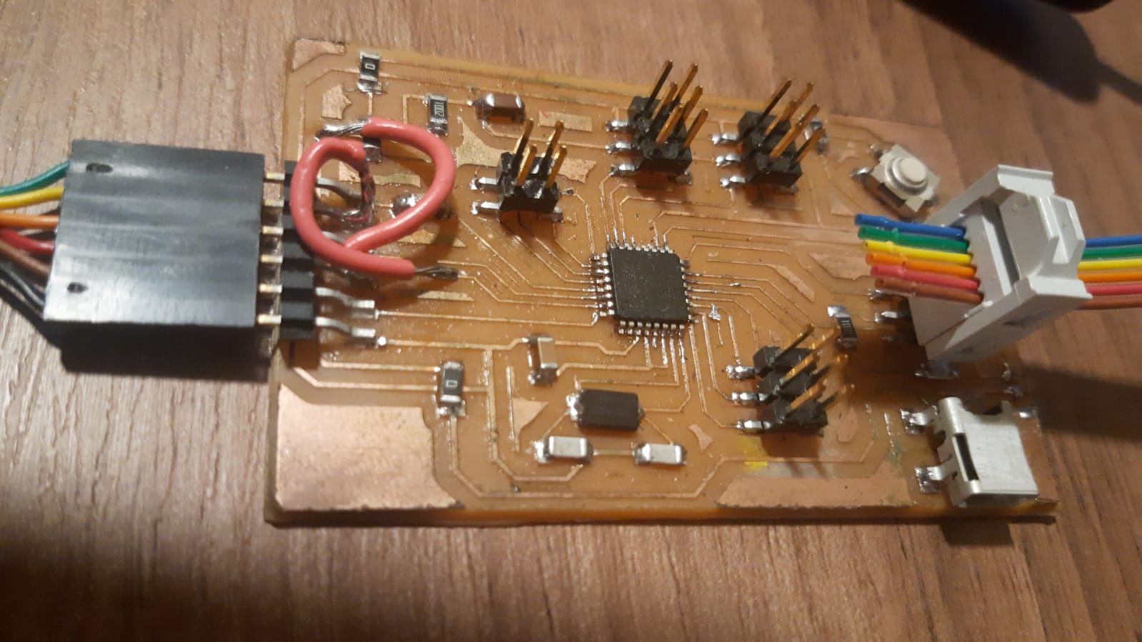
Design of the electronic circuit that emulates the central nervous system
I already have the programmer designed and working and the board with the atMega 328 is also designed as part of the task V and Task 11 respectively
For which we use the At mega 328, which has more pins, which makes it possible to integrate sensory and motor information.
Assembly
Now it’s time to put all the pieces together and make it work
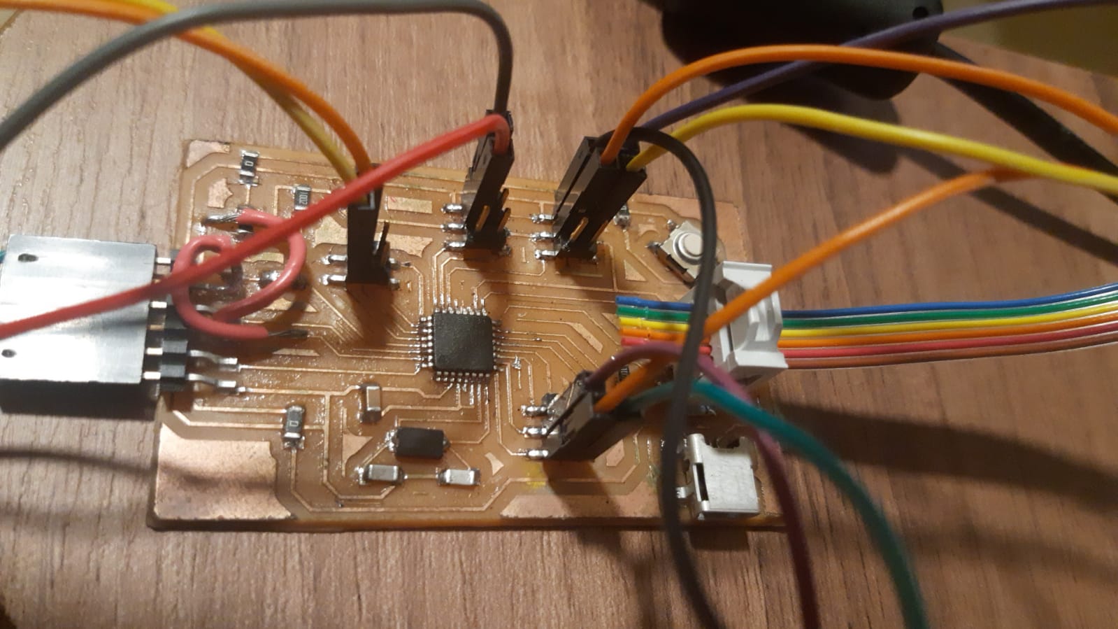
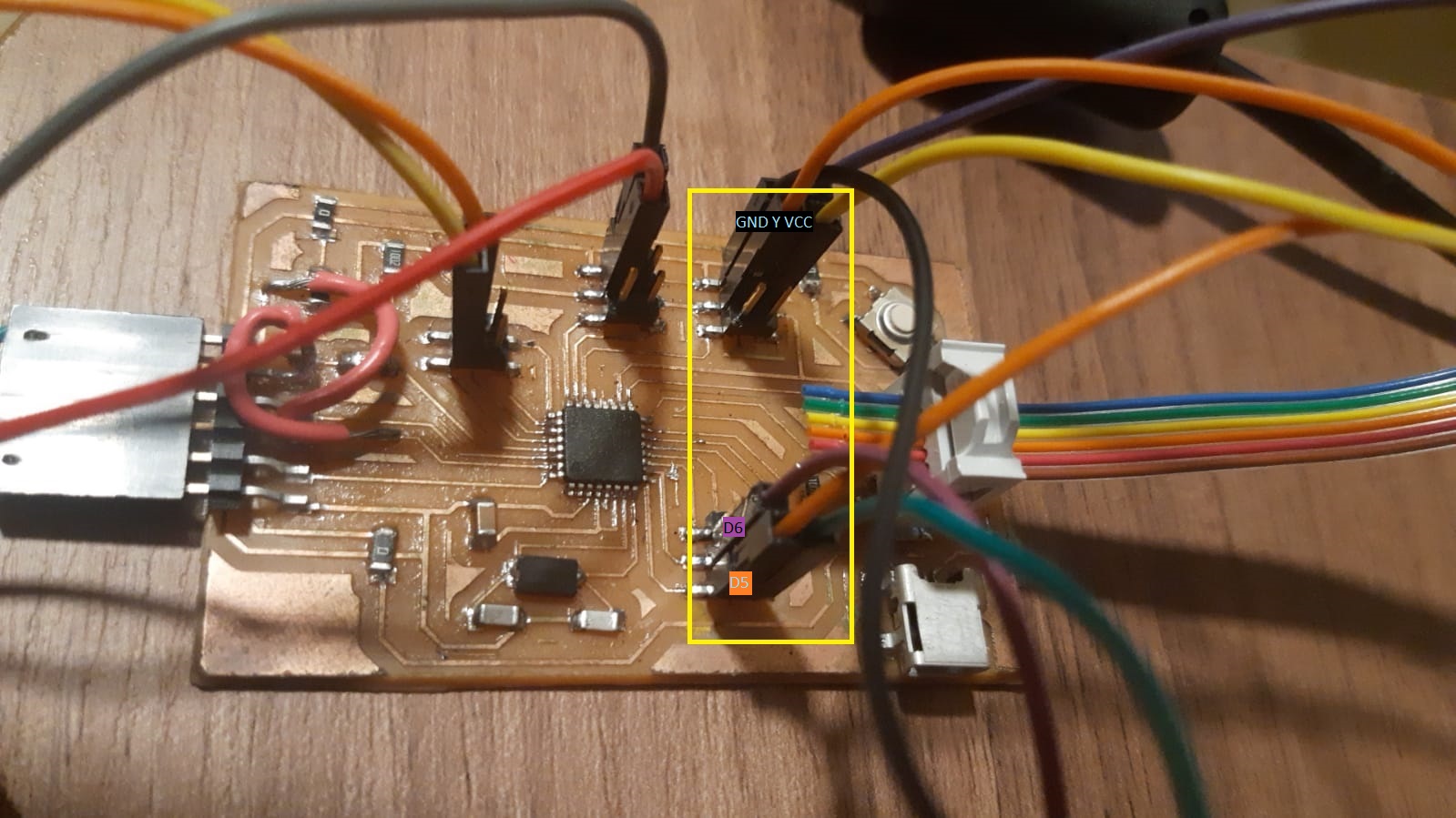
MPU6060 Sensor Pin Analogic 5 (SDA) and Pin 4 (SCL) GND and VCC 5v Pin 2 INT (interuptor) I still don’t know if it worked

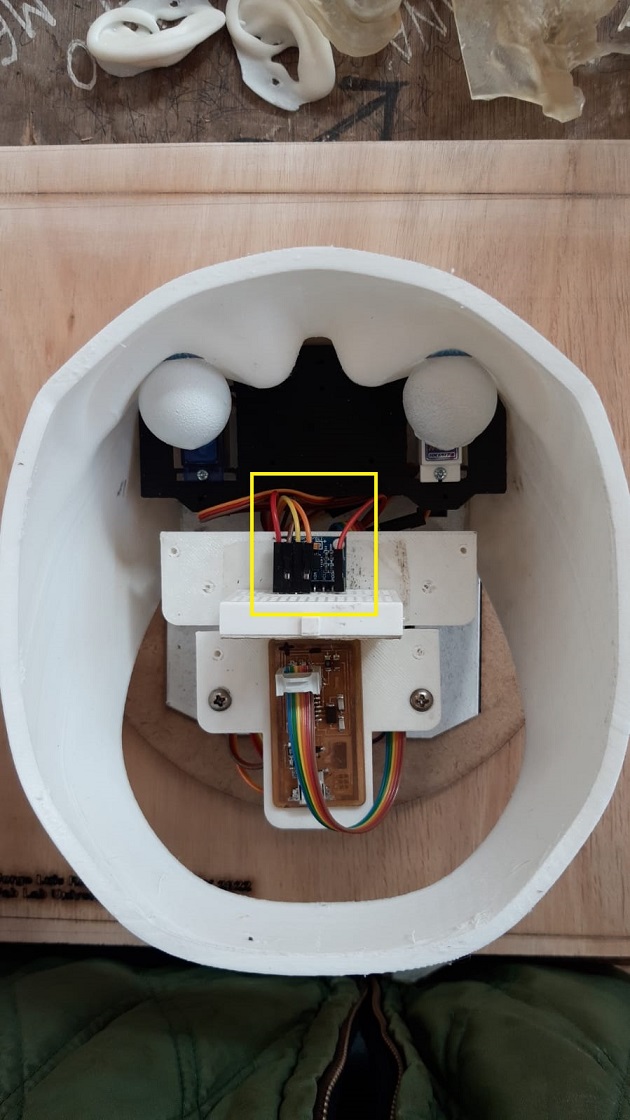
Servomotors actuator Pin digital 5 y 6 GND and VCC
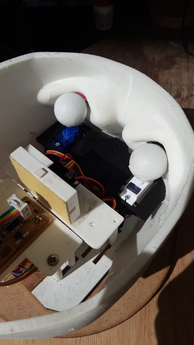
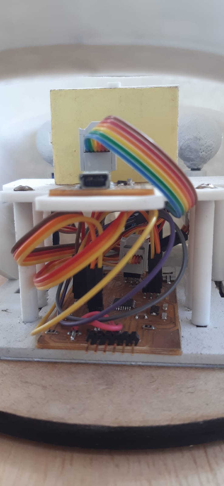
Components on their corresponding platforms
Project working properly Proyect working
Bill of material and cost
For the fase: PLA PLUS and for the eyes the Resin (3D Printer Curable Resine)
A full 1.75mm PLA plus thread costs $20
High Precision UV Curing 3D Resin costs $31
For the internal supports: I used 3 mm MDF wood and PLA plus.
12 pieces of MDF Wood of 12 x 24 inches of 3 mm costs $39
For the main external support: I used 13mm laminated wood
A 3 x 1.5 meter piece of 15mm thick plywood costs approximately $20
For the integrated circuit the copper plates and welding of the components with tin
One copper plates cost $5
I used a MPU 6050 sensor and two sg90 servo motors
MPU 6050 sensor cost $10
Servomotor sg90 cost 2$
For the rotary motion I used a ball bearing embedded in a circular plastic that was originally made for a pulley
One ball bearing cost $8
Other materials:
white synthetic Paint cost $30
wood screws
Glue for Wood
Materials such as PLA plus, Resin, wood, copper plate were materials shared with other projects, which could correspond to 1/5 of the total value.
The materials that I did have to acquire and absorb the expense were: the MPU 6050 and the synthetic white paint.
The microcomponents do not have a very high cost and considering their variety I do not see the need to detail them
Files:
2D and 3D Modeling Process
Internal plataforms
Electronics design
Future proyect
This does not exactly emulate the anatomy of the human being, considering that at the central level there are nuclei on each side that receive information from the ear on the corresponding side.
I think, although I clarify that electronics is not my forte, that the atMega328 could process and simulate the two right and left cores and it is only a matter of code (I don’t know) and there would be no need to have two right and left microprocessors
The same thought would apply to the actuator function of the microprocessor.
As we can see in the figure, the motor nuclei are independent from the sensory nuclei, but they are interconnected and to further complicate the connections that go from the sensory nuclei to the motor nuclei, they are crossed.
Below graph of the vestibulo-oculomotor reflex