7. Electronics design
group project:
use the test equipment in your lab to observe the operation of a microcontroller circuit board
individual project:
redraw an echo hello-world board, add (at least) a button and LED (with current-limiting resistor) check the design rules, make it, and test that it can communicate extra credit: simulate its operation
Group project:
Individual project:
Tutorial Eagle – Fusión 360
I attended a tutorial on Eagle - Fusion 360 suggested by the instructor Tutorial Eagle
Steps to manufacture of the Hello-world board with button and led light
(make the schematic with Eagle – Fusion 360)
- Identify and verify if we have all the components of the circuit
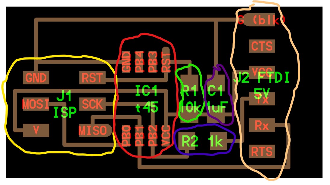
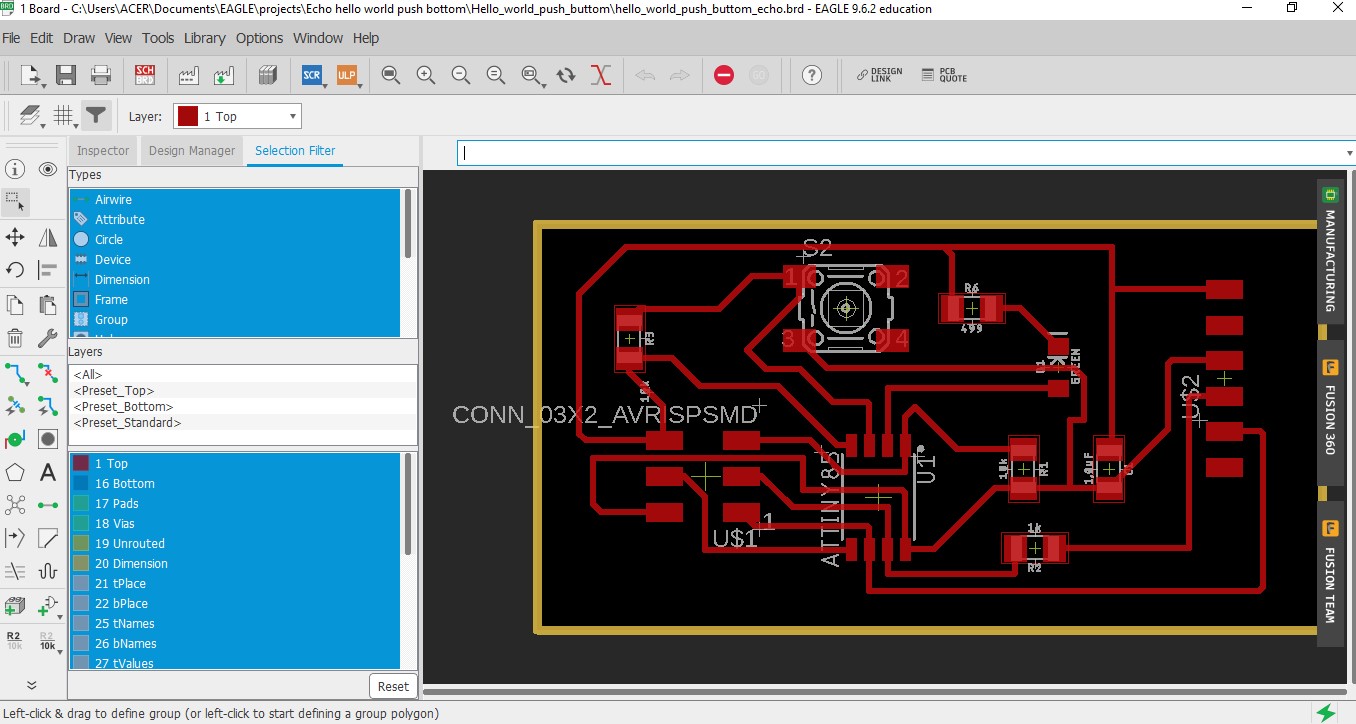
- I add the components to my circuit including the led and the buttonI. Schematic Eagle
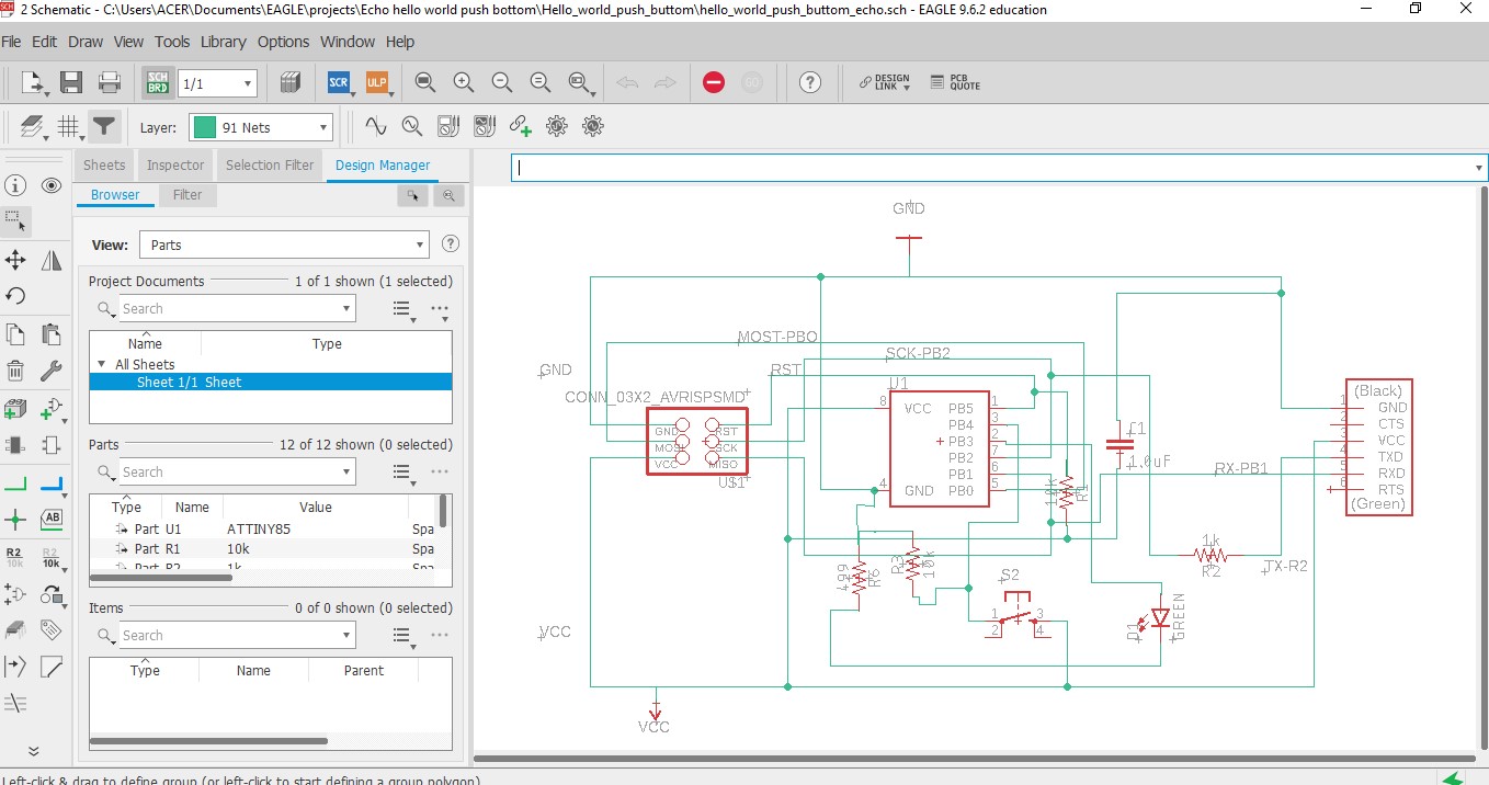
- Create a table with the characteristics of the components
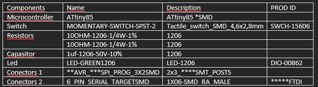
Obs: We use the ATtiny85 microcontroller in the schematic because it is compatible with ATtiny45 (same pins).
The (1206) corresponds to the footprint
(SMD) surface-mount device. Is an electronic device for which the components are mounted or placed directly onto the Surface of the PCB
(AVR) automatic voltaje regulator
(ISP) internet service provider
(SMT) surface-mount technology
*** (FTDI) future technology devices international
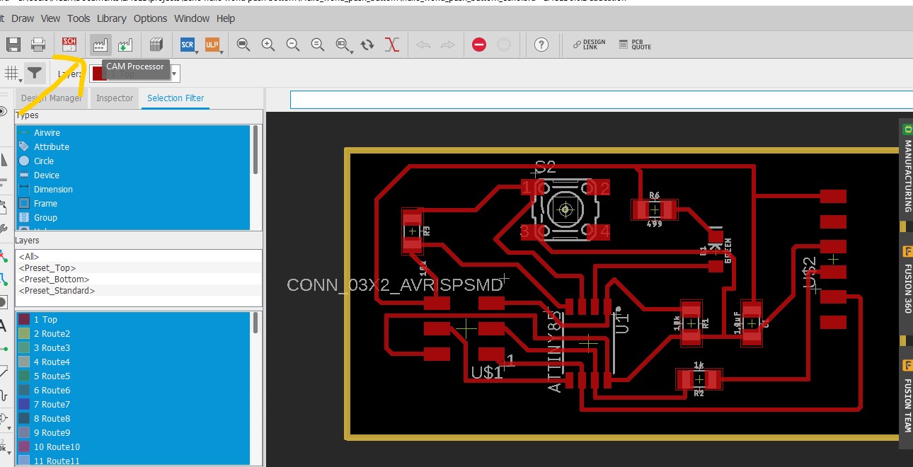
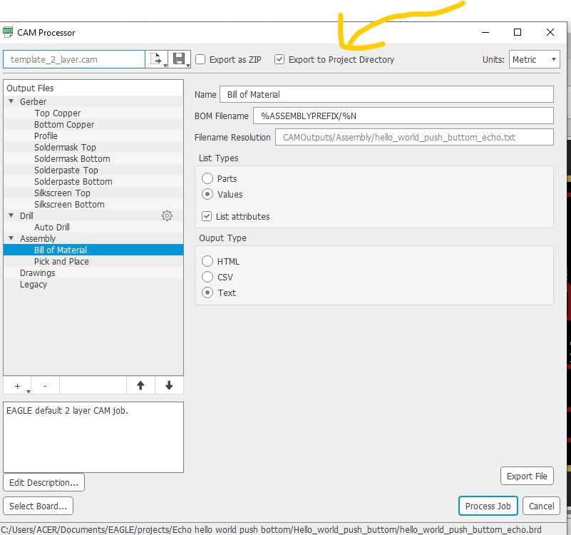
- The tracks with a diameter of 0.4 mm are created and the Berger file is generated with the CAM processor.
Files: Eagle_fusion_Archives
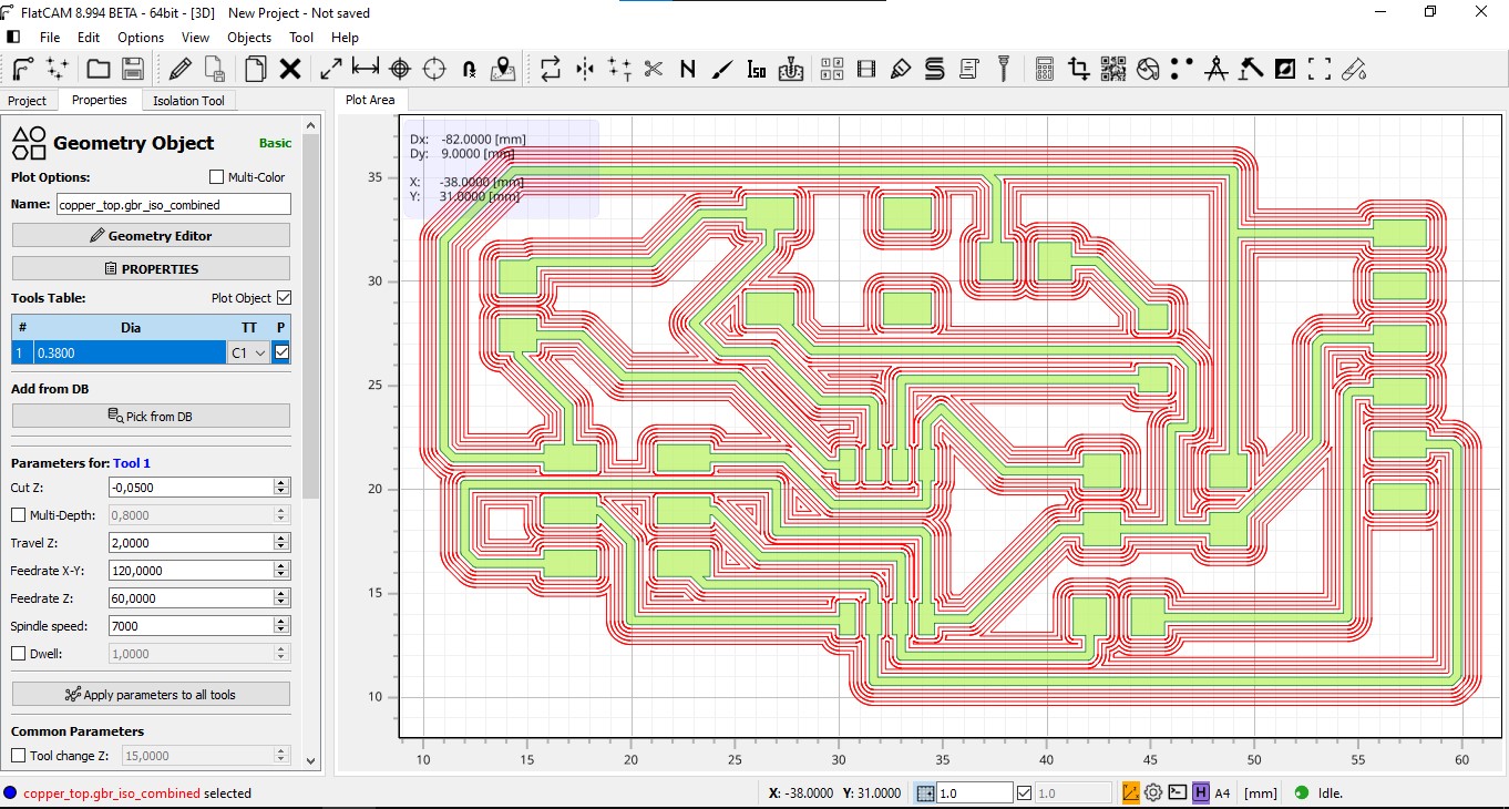
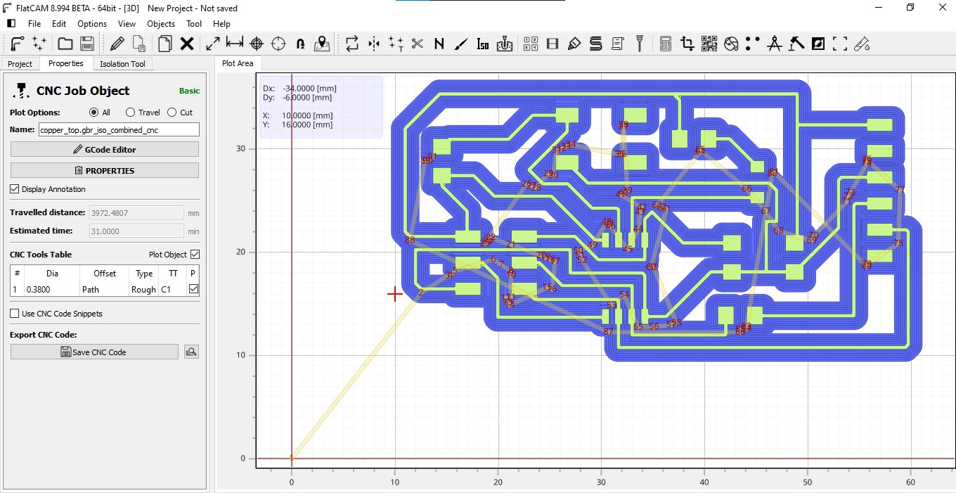
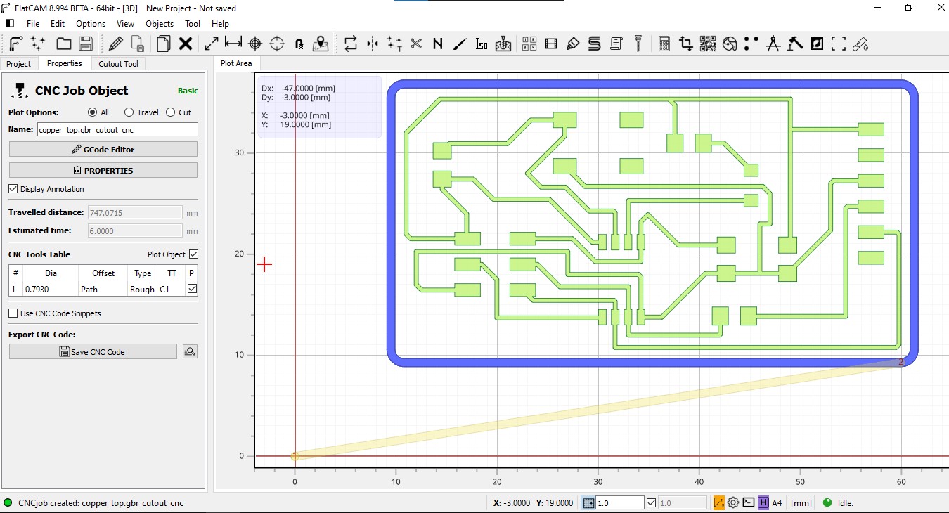
- The CNC of the PCB and the Cutout of the PCB (Printer Circuit Board) is generated with FlatCAM.
Geometric object
CNC PCB
CNC PCB Cutout
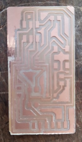
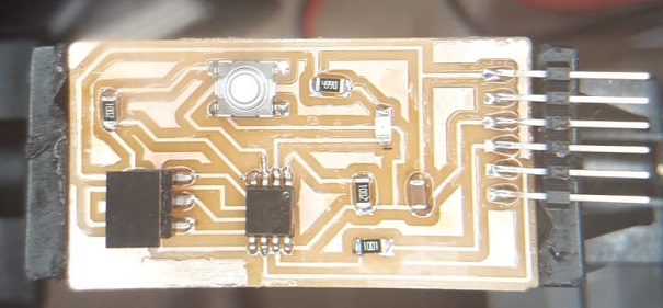
- The PCB is machined and its components are welded
Machining Circuit

PCB machined
PCB welded components
Other considerations arising from questions from the global evaluator
Could you explain how did you calculate the needed resistance ?
Did you calculate the Design Rules ? Please, explain how you did it.
The calculation to use the LED
I look at the datasheet of the LED to use
https://cdn-reichelt.de/documents/datenblatt/A500/SMD1206_ENG_TDS.pdf
I get the value of the current intensity corresponding to that LED: 20 mA
I have two data to apply the ohm’s law formula
Photo Ohms Law
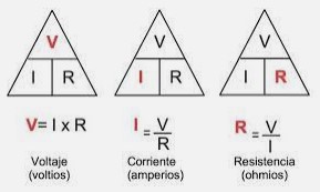
V = R x I
R = V / I
R = 5 volts / 0.02 A = 250 ohms
It is suggested to place higher resistance values than the calculations to provide greater protection.
Photo of 499 SMD Resistor

Design Rules:
1- Define what we want to do: in this case we want to incorporate an LED into the circuit and have it interact with a button
2- Make a list of the necessary components with their size and electronic characteristics.
3- The design of the circuit (that is, the board where the circuit is going to be designed) is adjusted to the space where it is going to be and the necessary size so that the components are located comfortably inside it.
There should be more rules but those are the ones that come to mind at the moment
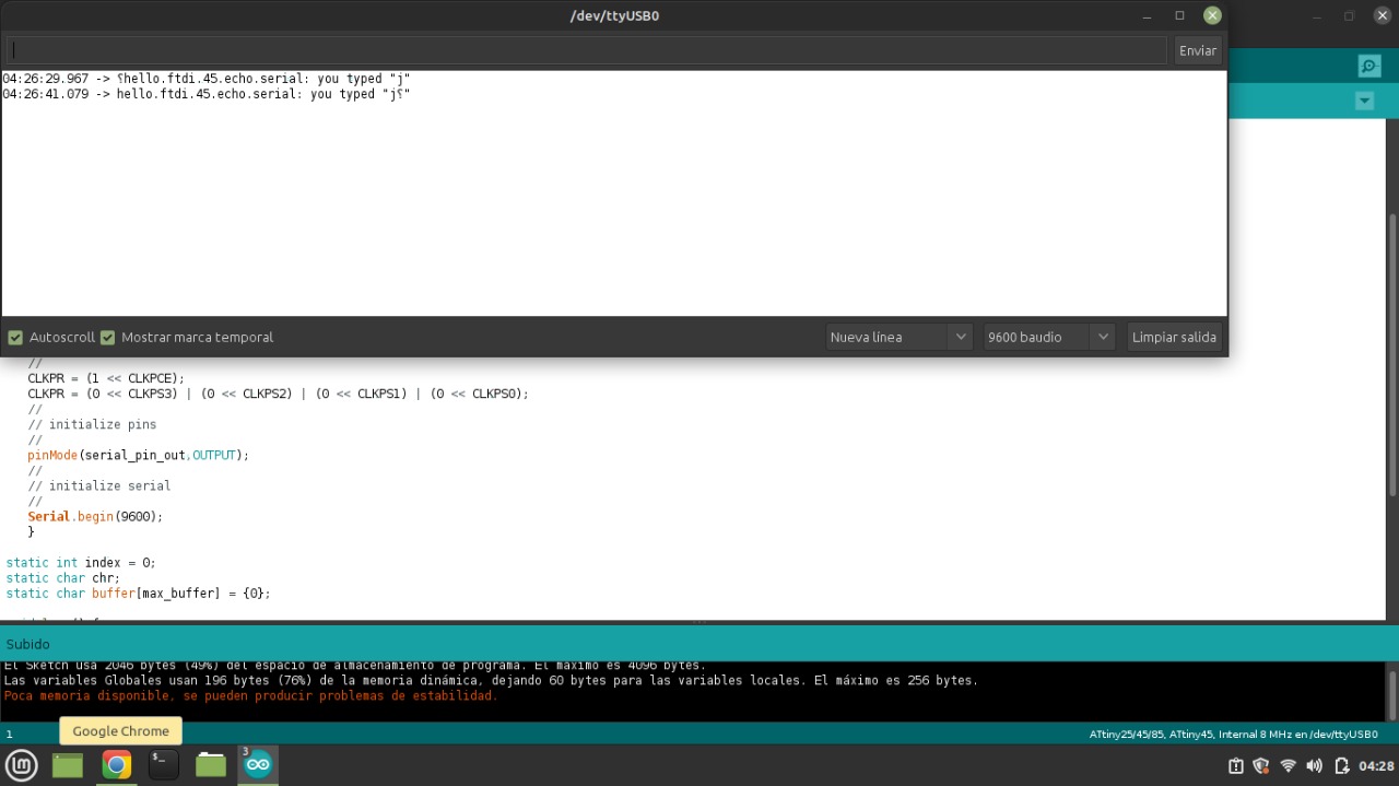
Conect Circuit for programation
To know how to connect always look at the GND pin (Earth)
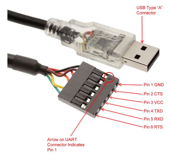
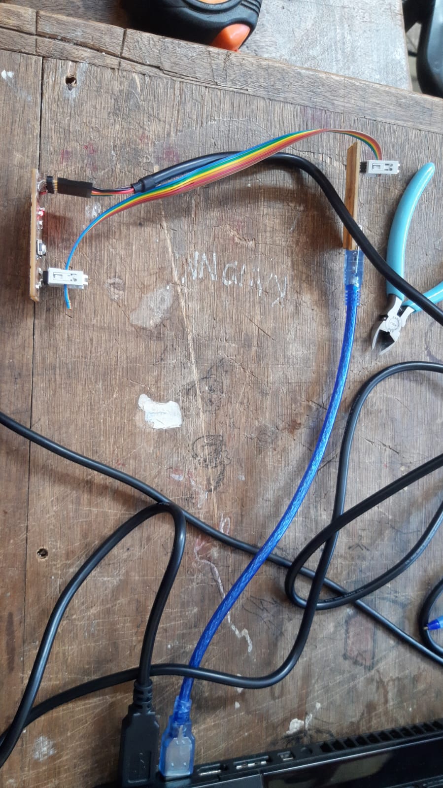
Conect the Circuit to programador
Step for programing:
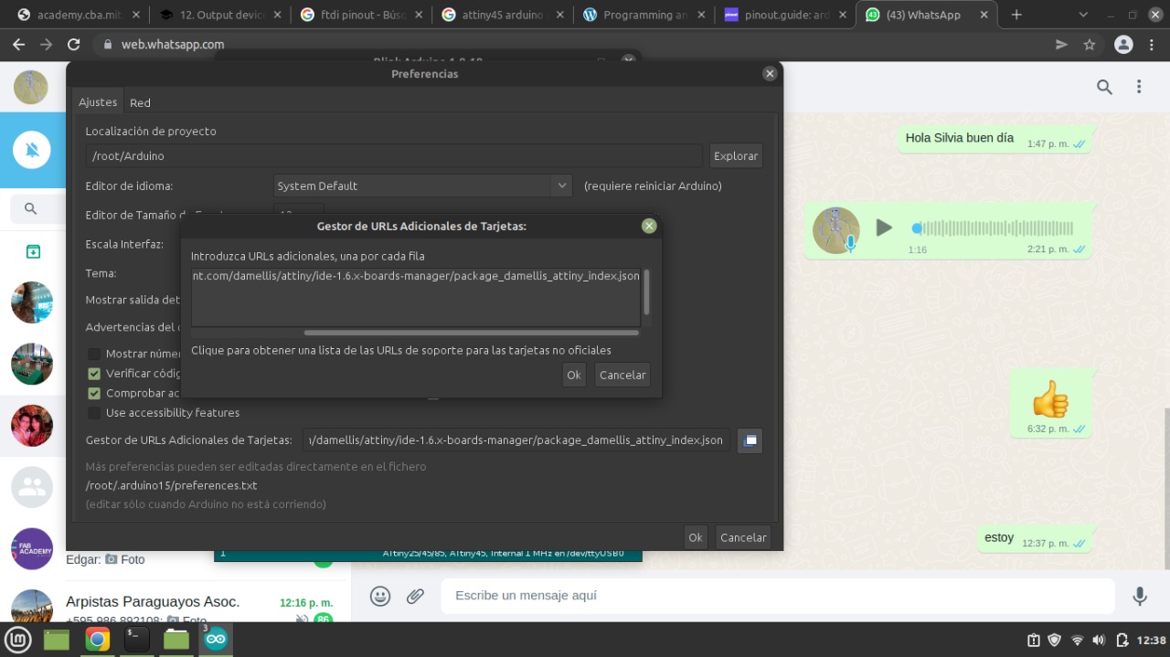
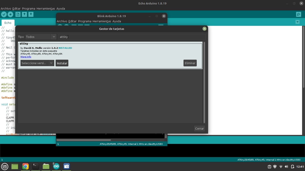
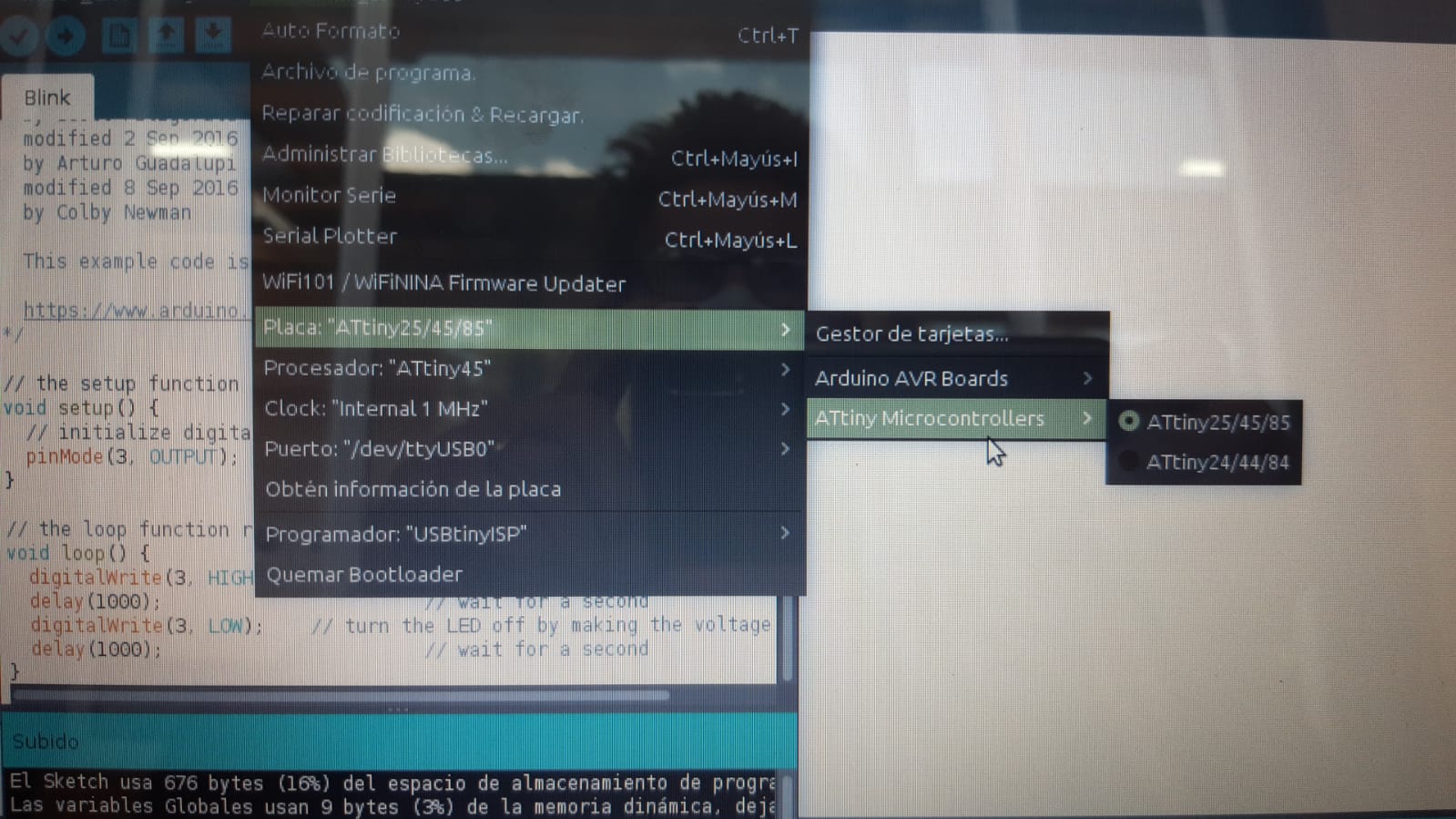
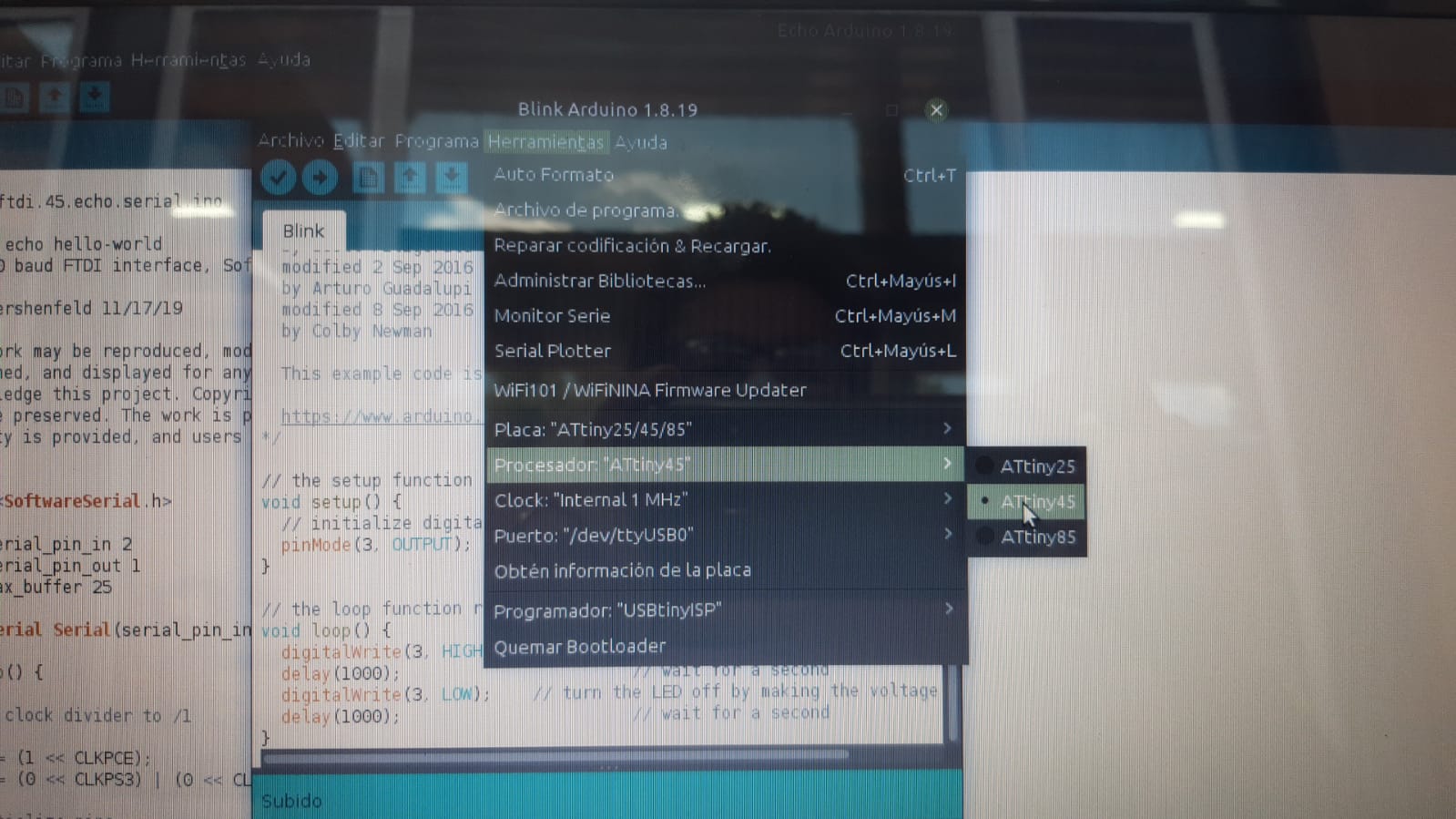
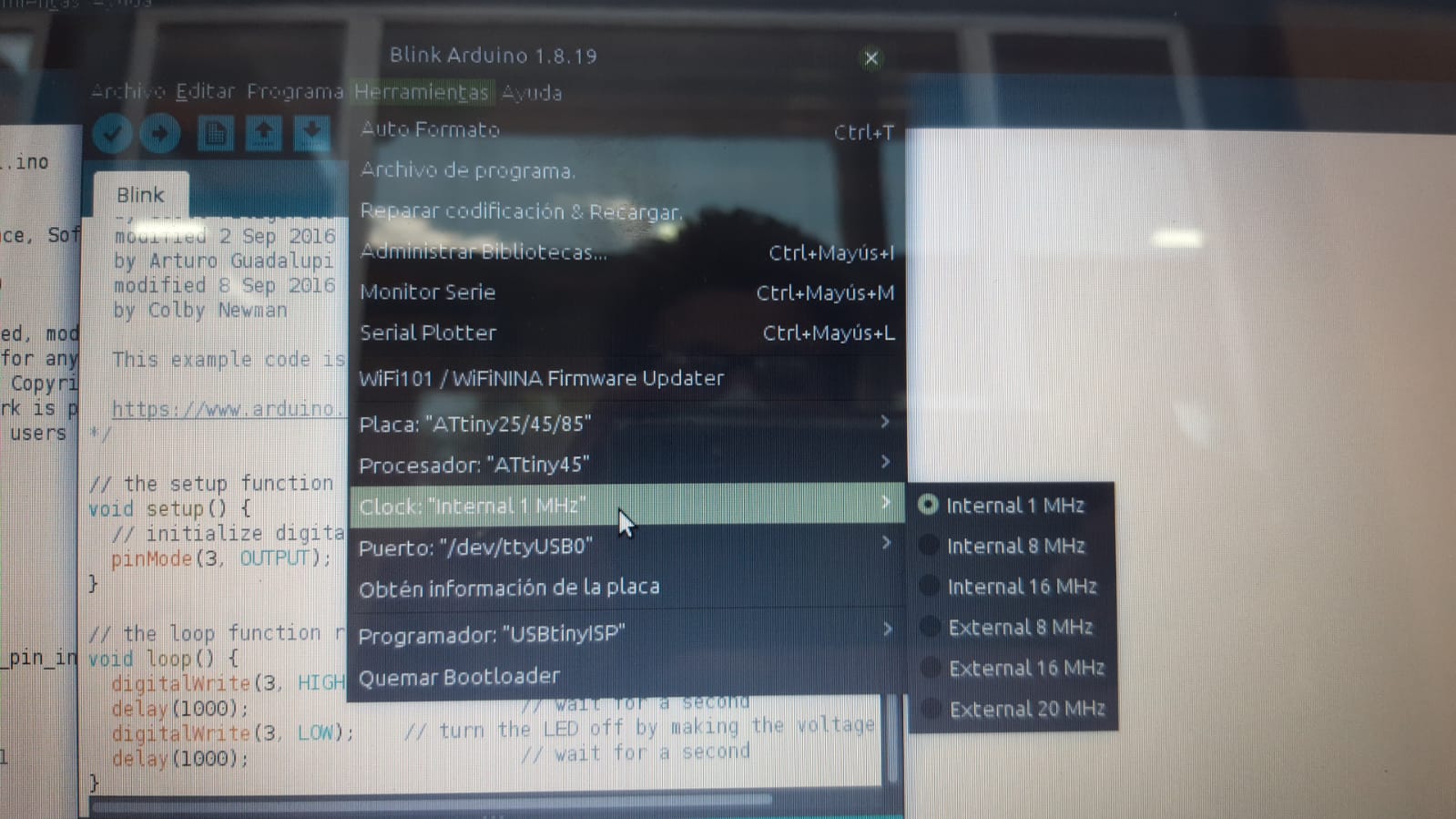
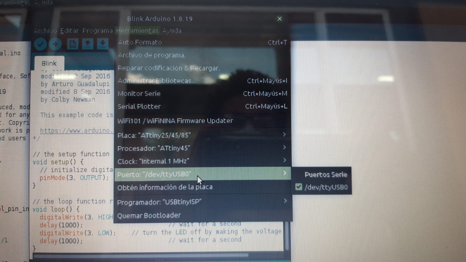
- Open of Arduino Sofware and instaling the support for Attiny 45
For that I used this enlace for to get the attiny librery
I include the support for ATtiny 45 to the arduino library
I charged the library to Arduino
Set parameters
Working buttom and led
For the led to turn on when you press the button
Source code
void setup() {
// put your setup code here, to run once:
pinMode (3, OUTPUT);
pinMode (4, INPUT);
}
void loop() {
// put your main code here, to run repeatedly:
if (digitalRead (4))
{
digitalWrite(3, HIGH);
}
else
{ digitalWrite (3,LOW);
}
}
For the led to blink after pressing the button
Source code
int inicio = 0;
void setup() { // put your setup code here, to run once:
pinMode (3, OUTPUT);
pinMode (4, INPUT_PULLUP);
}
void loop() { // put your main code here, to run repeatedly:
if (inicio == 0)
{
if (digitalRead (4)) inicio = 1;
}
if (inicio == 1)
{
digitalWrite(3, HIGH);
delay (50);
digitalWrite(3, LOW);
delay (50);
}
}
For the led to blink during preseeing the button
Source code
void setup() {
// put your setup code here, to run once:
pinMode (3, OUTPUT);
pinMode (4, INPUT);
}
void loop() {
// put your main code here, to run repeatedly:
if (digitalRead (4))
{
digitalWrite(3, HIGH);
delay (50);
digitalWrite(3, LOW);
delay (50);
}
else
{ digitalWrite (3,LOW);
}
}
Echo hello-world