9. Embedded programming
Eight assignment
Embedded programming
assignment
individual assignment:
read the data sheet for your microcontroller
use your programmer to program your board to do something
extra credit: try other programming languages and development environments
group assignment:
compare the performance and development workflows for other architectures
¿What is one microcontroller?
It is a compressed microcomputer used to control the embedded system functions in robots, office machines, motor vehicles, home appliances & other electronic gadgest
The manufacturing technology used for its controller is VLSI
What does it means VLSI?
Very large-scale integration, or VLSI, is the process of creating an integrated circuit made up of millons of transistor on a single chip
General knowledge about integrated circuits and some terms
Asking in Google for integrated system in the contexto of electronics, I got:
An integrated circuit (IC), also know as a chip or microchip, is a small-sized structure of semiconductor material, usually silicon, with a few square millimeters of Surface (área), on which electroniccircuits are generally manufactured by photolithography and which is protected within a plastic or ceramic package. The package has metallic conductors suitable for making a connection between the integrated circuit and a printed circuit
IC were made posible by experimental descoveries showing that semiconductor device could perform fhe functions of vacuum tubes.
Usefull terms:
Wafer “oblea”: a wafer or sheet is a thin plateo of a semiconductor materal, such as silicon, with which microcircuits are bluit.
Microcontroller: (sometime calle dan MCU or microcontroller unit) is a single integrated circuit (IC) that is typically used for a specific application and designed to implement certain tasks
* Microprocessor: It is a central processing unit on a single integrated circuit chip that contains millons of very small comonents, including transistor, resistors, and diodes that work together
* ROM: Read-Only Memory. Is one type the ROM memory
* Serial port: is a communication interfaz. The main difference between a serial port and parallel port is the way information is transferred. The serial port transmits the information bit by bit, one ofter another, Parallel ports, by contrast, can transmit multiple bits in parallel over miltiple chanels
* VSS: grounded or negative supply voltaje
* EEPROM: Electricaly Erasable Programmable
SRAM (Static Random Access Memory) is one type of tecnology of RAM memory based on semiconductors, capable of maintaining the data, as long as it is powered, without the need for a refresh circuit
AVR is a family of microcontrollers developed since 1996 by Atmel, acquired by Microchip Technology in 2016. These are modified Harvard architecture 8-bit RISC single-chip microcontrollers. AVR was one of the first microcontroller families to use on-chip flash memory for program storage, as opposed to one-time programmable ROM, EPROM, or EEPROM used by other microcontrollers at the time.
* What does it means CLK?
* What does it means ALU?
* MIPS: is a measure of a computer’s processor speed.
* ADC: Analog to Digital Converter
* PWM: Pulse width modulation
Components of microcontrolador
Then, the different components used in a microcontroller are a processor, peripherals, and memory Components: 1. An 8 or 16 bit microprocessor. 2. A small measure of RAM 3. Programable ROM and flash memory 4. Parallel and serial I/O 5. Timers and signal generators 6. Analog to digital to analog convertion (ADC y DAC)
How are Microcontrollers Types Classified?
- According to the number of bits: 4, 8 ,16, 32 bit
- According to memory devices: Embebbed memory and external memory
- According to instruction set: CISC (Complex Instruction Set Computer) and RISC (Reduced Instruction set Computer)
- According to memory architecture: Harvard memory (has a disimilar memory address space for the program and data memory) and Princeton (has a common memory address for the program memory and data memory)
Microcontroller types
a. 8051
b. Renesas
c. AVR
I. TinyAVR / II. MegaAVR / III. XmegaAVR
d. PIC
e. MSP
f. Hitachi
g. Motorola
Difference between 8051 and AVR controllers * 8081s are 8-bit controllers base don CISC architecture, AVRs are 8-bit controllers base don RISC architecture * 8051 consume more power tan an AVR microcontroller * In 8051, we can program easily tan the AVR microcontroller * The speed of AVR is more tan the 8051 microcontroller
About Attiny45
Atmel 8-bit AVR Microcontroller with 2/4/8K Bytes In-System Programmable Flash
ATtiny25/V / ATtiny45/V / ATtiny85/V
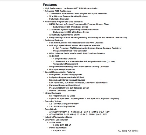
Features:
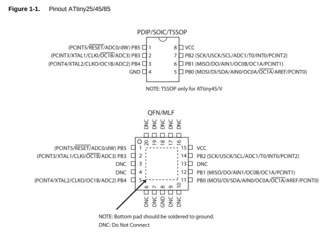
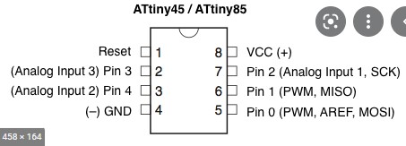
Pin configurations
Overview
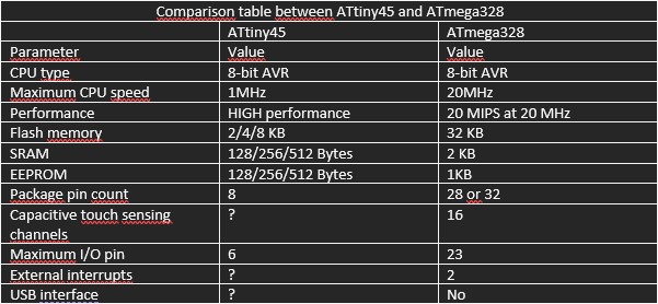
The ATtiny25/45/85 is a low-power CMOS 8-bit microcontroller based on the AVR enhanced RISC architecture. By executing powerful instructions in a single clock cycle, the ATtiny25/45/85 achieves throughputs approaching 1 MIPS per MHz allowing the system designer to optimize power consumption versus processing speed
The AVR core combines a rich instruction set with 32 general purpose working registers. All 32 registers are directly connected to the Arithmetic Logic Unit (ALU), allowing two independent registers to be accessed in one single instruction executed in one clock cycle. The resulting architecture is more code efficient while achieving throughputs up to ten times faster than conventional CISC microcontrollers.
Sources
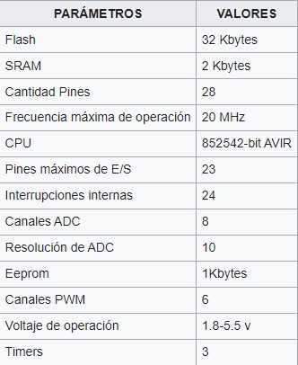
About ATMEGA328P
The ATmega328 is a single-chip microcontroller created by Atmel in the megaAVR family (later Microchip Technology acquired Atmel in 2016). It has a modified Harvard architecture 8-bit RISC processor core.
The Atmega328 AVR 8-bit is a high-performance integrated circuit that is based on a RISC microcontroller, combining 32 KB (ISP) flash memory with read-while-write capability, 1 KB EEPROM memory, 2 KB SRAM, 23 general purpose I/O lines, 32 general process registers, three flexible timers/counters with compare mode, internal and external interrupts, USART mode scheduler, one 2-wire byte-oriented serial interface, SPI serial port, 6 -10-bit channels A/D converter (channels in TQFP and QFN/MLF packages), programmable watchdog timer with internal oscillator, and five software-selectable power saving modes. The device operates between 1.8 and 5.5 volts. By executing powerful instructions in a single clock cycle, the device achieves 1 MIPS response, balancing power consumption and processing speed.
Currently (2020) the ATmega328 is commonly used in multiple projects and stand-alone systems where a simple, low-power, low-cost microcontroller is required. Perhaps the most common implementation of this chip is in the popular Arduino platform, in its Uno and Nano models.

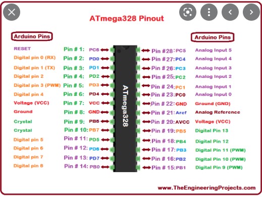
Pin comparison
ATmega328
ATtiny45
Comparation Table
Source
Datasheet_ATmega328
ATmega328_Wikipedia
Use your programmer to program your board to do something
Using a board I made with attiny45
In basic examples the Arduino you can trouve o code “Fade”
Fade CODE
int led = 9;           // the PWM pin the LED is attached to
int brightness = 6;    // how bright the LED is
int fadeAmount = 1;    // how many points to fade the LED by

// the setup routine runs once when you press reset:
void setup() {
  // declare pin 9 to be an output:
  pinMode(led, OUTPUT);
}

// the loop routine runs over and over again forever:
void loop() {
  // set the brightness of pin 9:
  analogWrite(led, brightness);

  // change the brightness for next time through the loop:
  brightness = brightness + fadeAmount;

  // reverse the direction of the fading at the ends of the fade:
  if (brightness <= 6 || brightness >= 36) {
    fadeAmount = -fadeAmount;
  }
  // wait for 30 milliseconds to see the dimming effect
  delay(500);
}
I had to make some changes in the code
I needed to change the pin 9 for pin 0.
The pin 0 and 1 the attiny 45 have PWN (Pulse Width Modulation)int brightness = 6 for 0 (brightness <= 6 for 0 || brightness >= 250 for 100)
Final CODE
*/

int led = 0;           // the PWM pin the LED is attached to
int brightness = 0;    // how bright the LED is
int fadeAmount = 1;    // how many points to fade the LED by

// the setup routine runs once when you press reset:
void setup() {
  // declare pin 0 to be an output:
  pinMode(led, OUTPUT);
}

// the loop routine runs over and over again forever:
void loop() {
  // set the brightness of pin 9:
  analogWrite(led, brightness);

  // change the brightness for next time through the loop:
  brightness = brightness + fadeAmount;

  // reverse the direction of the fading at the ends of the fade:
  if (brightness <= 0 || brightness >= 100) {
    fadeAmount = -fadeAmount;
  }
  // wait for 30 milliseconds to see the dimming effect
  delay(30);
}
The Result, working the servo
video showing servo movement