5. Electronics production
assignment
group assignment:
  characterize the design rules for your in-house PCB production process
  extra credit: send a PCB out to a board house
individual assignment:
  make an in-circuit programmer that includes a microcontroller:
     extra credit: customize the design
     mill and stuff the PCB
     test it to verify that it works
     extra credit: try other PCB processes
Team work
We saw two tutorials made by our instructor: how to install FLATCAM and how to generate the file (CODE) for the machining process.
The first tutorial was how to install FlatCam
The second tutorial
It is about how to generate the file and CODE for the machining process:
We learned to install the program, to change the color (inverted color) and to know the resolution (or DPI value) of the print of the predefined gerber image and that same resolution we must place in the program FLATCAM, we learned too to place the parameters to generate the CODE.
We verify the difference between one size and another of the drill, in this case we use 1/32 and 1/64. We learned that in general to make a cut 1/32 and to make a track 1/64
We transformed inch in mm:
1/32 inch or 0,031 inch = 0,793 mm
1/64 inch or 0,0156 inch = 0,396 mm
We learned about the importance of the rotational speed rpm and the speed of movement in its axes to prevent the drill break it.
We were presented with two problems:
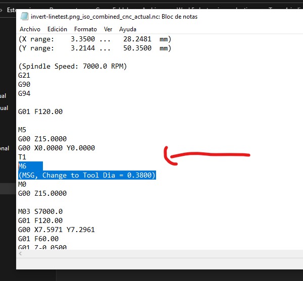
The first was with the CODE, the program generated an M6 which we had to remove from the code.
The second was the appearance during the start of drilling to cut the plate, the part that carries the drill cutter rose abruptly and moved rapidly in all axes. This happened because the drill cutter reached its stop in the Z axis because it was very stuck in the piece that carries it (I don’t remember the name)
Before discovering what the problem was, we got to know a simulator program for the machine and confirmed that there was no CODE error.
Individual work
We carry out the same process, but now ourselves, from generating the CODE, machining and then placing the components and finally testing if everything was connected correctly
The steps were the following:
First part:
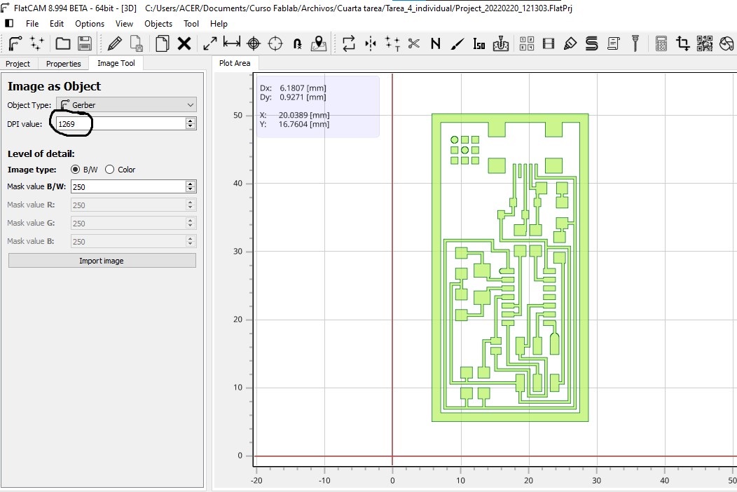
First step: I select in the FLATCAM program to import image as object: here we place the resolution of the image that previously through the GIMP program we invert the color and confirm its resolution.
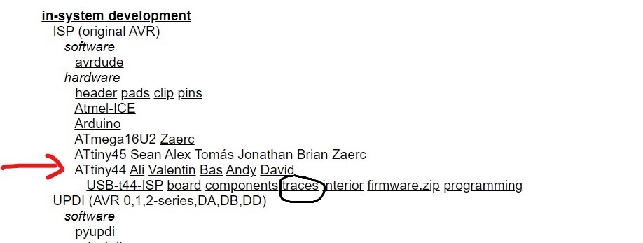
Process to get the image: I had to access the schematic of the FabAcademy 2022 and in the module of the week of the assignement section (make an in-circuit programmer that includes a microcontroller), that’s where I got the pre-assigned circuit model.
The first thing I did was download that model to a folder of my images.
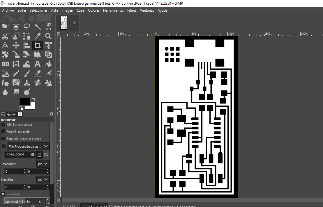
With the GIMP program I invert the colors of the image.
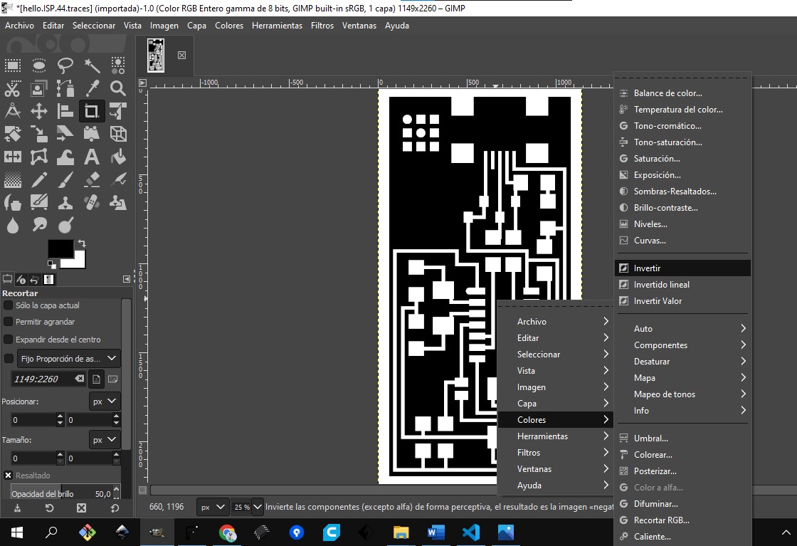
I see the resolution of the image (the DPI value)
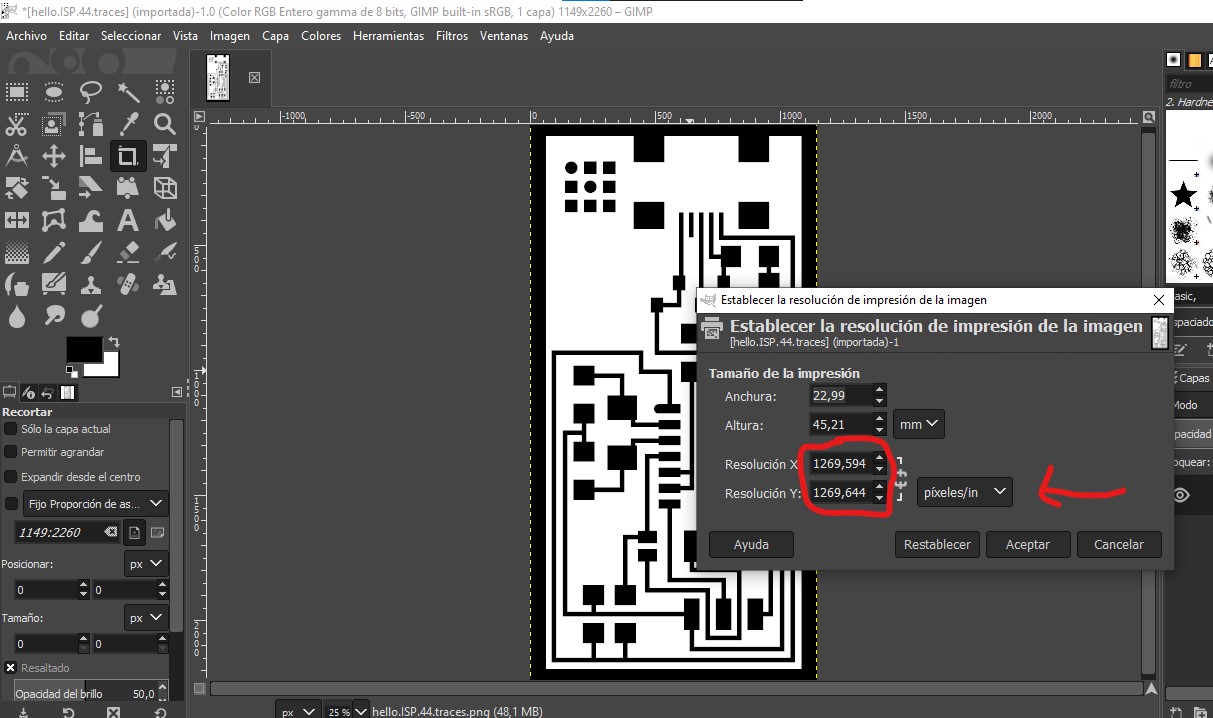
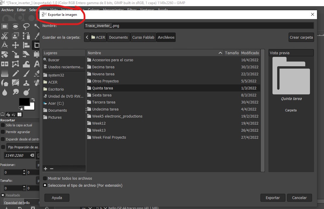
You must export to archive folder
Second part:
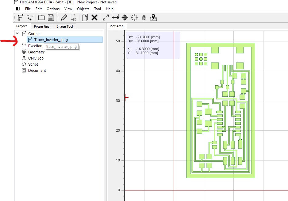
First step: Import image to FLATCAM: In DPI value you must to put the value correct and place it on the positive side of the x/y coordinates and close to the beginning of the angle with a certain margin.
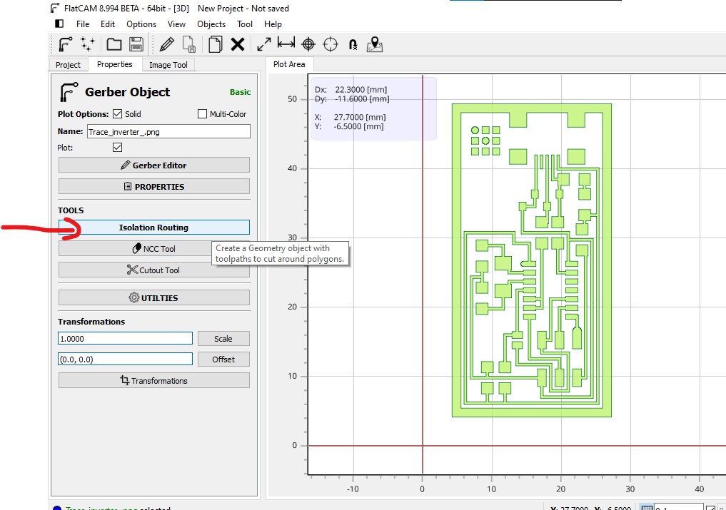
Second step: Start the project by double clicking on the name of the gerber file
And then clicking on Isolations routing
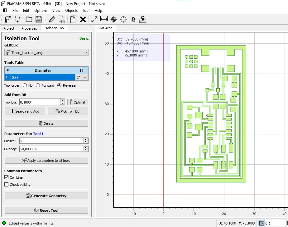
Complete the parameters of:
Diameter of the tip/mill: 0,0156 inch = 0,396 mm
TT: C1/
Passes: 5 (number of geometric lines)
The % of Overlap (corresponds to the % of the diameter of the tip/mill): the ideal overlap turned out to be 50%.
Apply and Generate
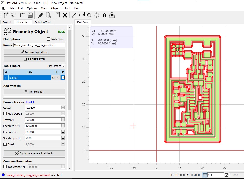
Forth step: In the same windows you must to clik in Generate the CODE and then save the Project and the Code in your folder of archives
fifth step: we demarcate it with a cutting line, we can import it as an image or do the same with FLATCAM
Doing whit FlatCam:
First in the Projects items you must disability the Geopmetrics and the CNC code
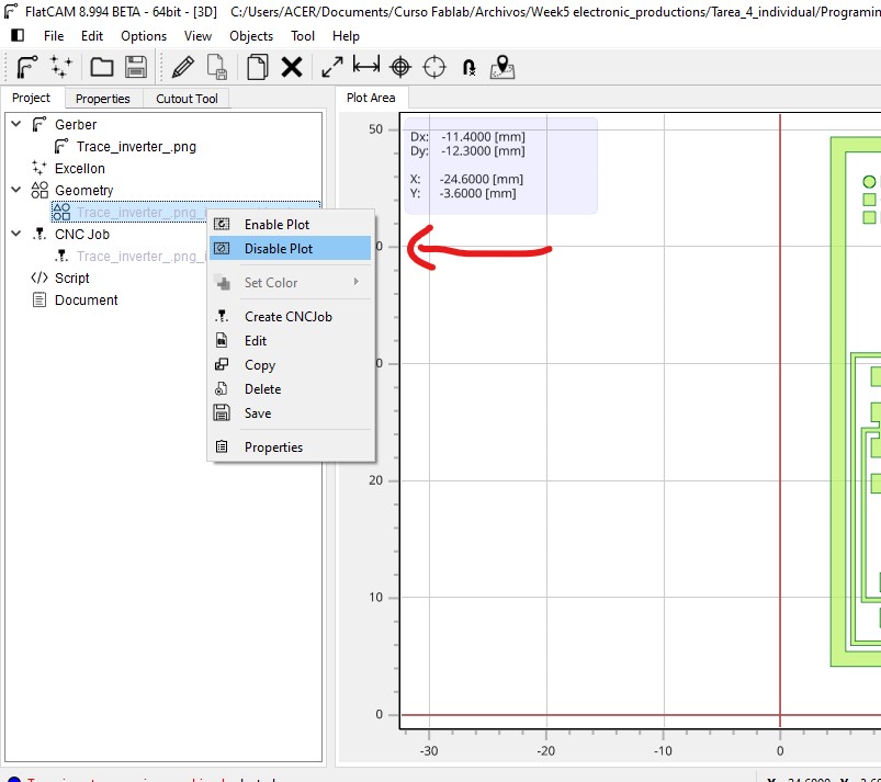
Second in the same windows you must to clik egain in Trace_Inverter_png Thirth you must select “cutout tool”

ForthIn the cutout tool you must complete the parameters:
Tool Dia: 0.793
Cut Z: -1.8 (becouse the plac is the 1.5 mm)
Margin: 0.3 mm (This is important for separed the cutline of the Isolation routing)
Gap: none
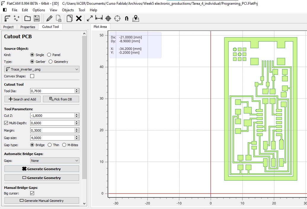
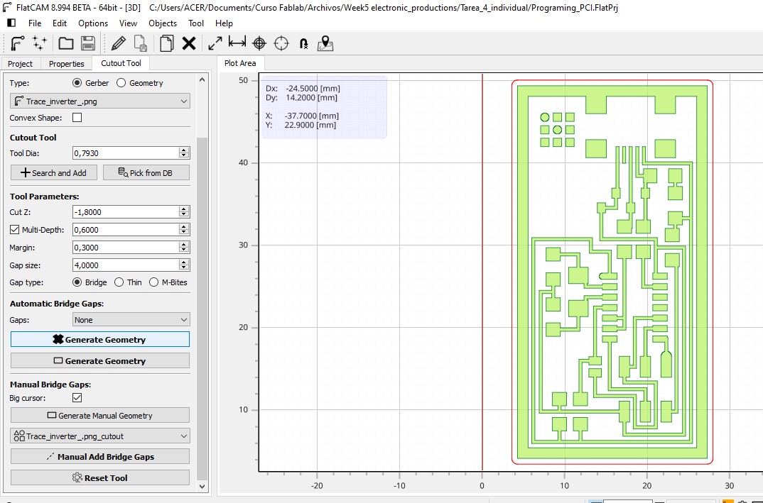
In the same cutout tool windows you must generate geometria
In “Properties” Create the CODE for the cutting line. Remember that for the cutout the diameter of the tip was 1/32
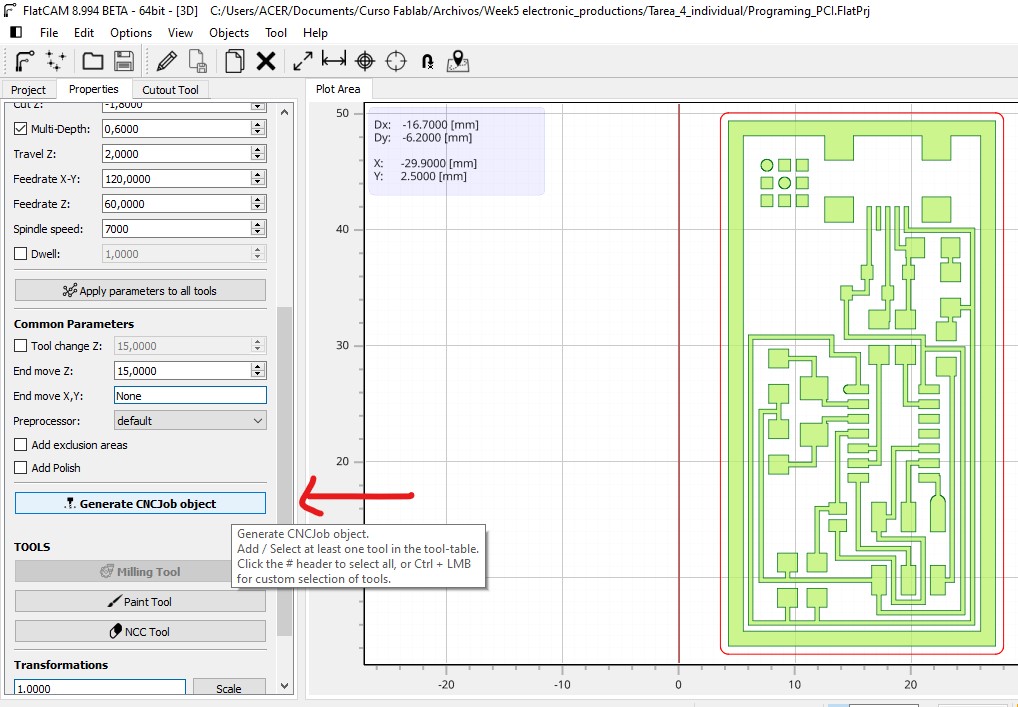
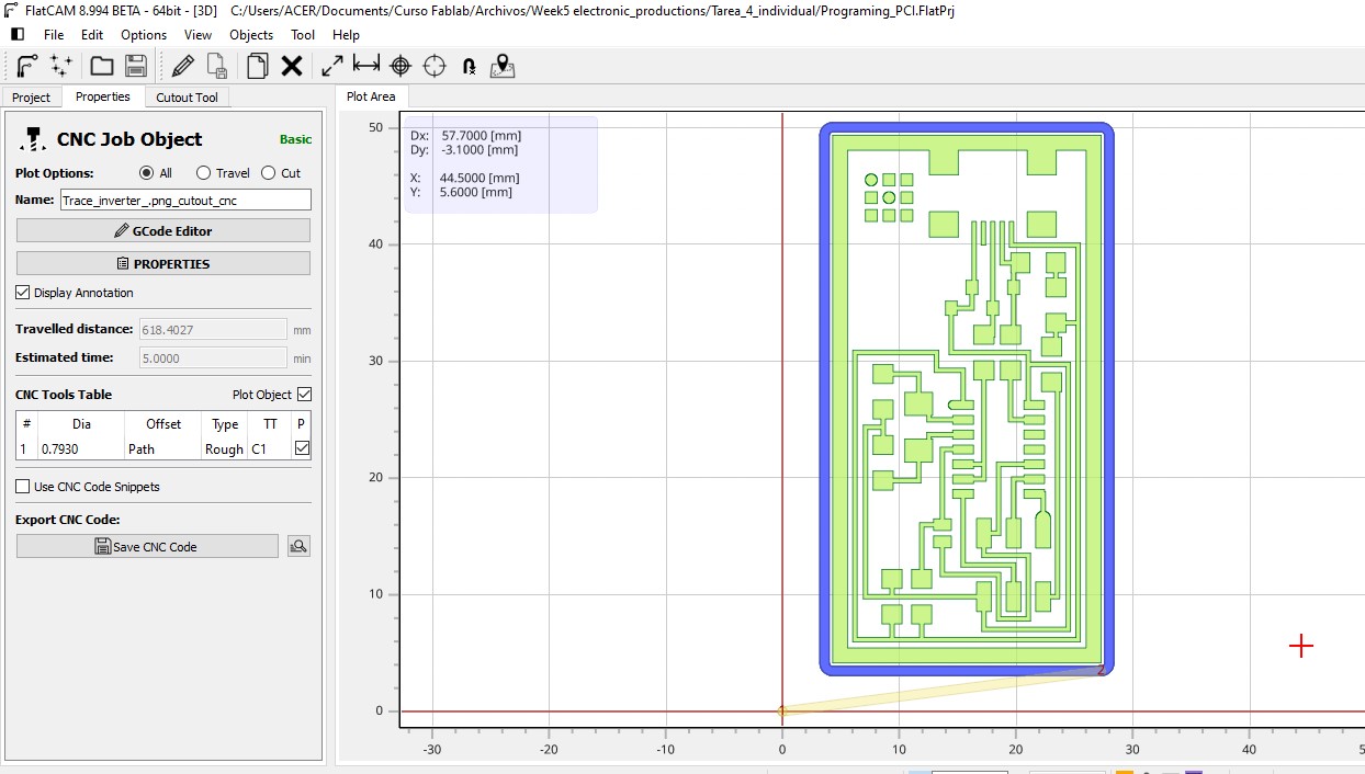
We need delete inside of CODE “M6” before go to the maching CNC
Plot CNC
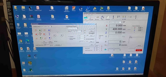
There are two formats that the RML and NC work machine, we must select NC
We prepare the machine by placing the drill cutter and placing the drill tip at the drill start point and leveling the drill cutter tip exactly at the height of the plate (manually)
Then we go to the computer to load the CODE to the program and start drilling
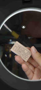
Final result
I had to clean the board because there were a lot of unnecessary copper filaments left (This problem you can resolve in the option Overlap changing 10 % for 30 or 50 %)
Soldering of the components of the board I managed to solder all the components
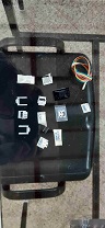
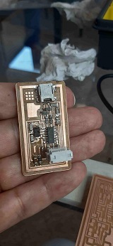
I learned that to get a good solder it is necessary to use the solder paste and the tip of the soldering iron always clean The technique would be to first heat the surface and then bring the tin closer
We perform the test It doesn’t happen I probably had problems at the USB pin level.
I managed with help to fix the soldering of the USB pins
Programing the Programer
Firs I needed to install two software: Avrdudes and GCC
GCC: It ‘translates’ the programming languages to machine language. Or to put it in another way, it converts our source code to executable instruction file for computers. GCC stands for “GNU Compiler Collection”. GCC is an integrated distribution of compilers for several major programming languages.
The steps were:
Make Clean
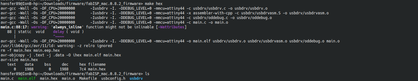
*  Make Hex
*
Make Hex
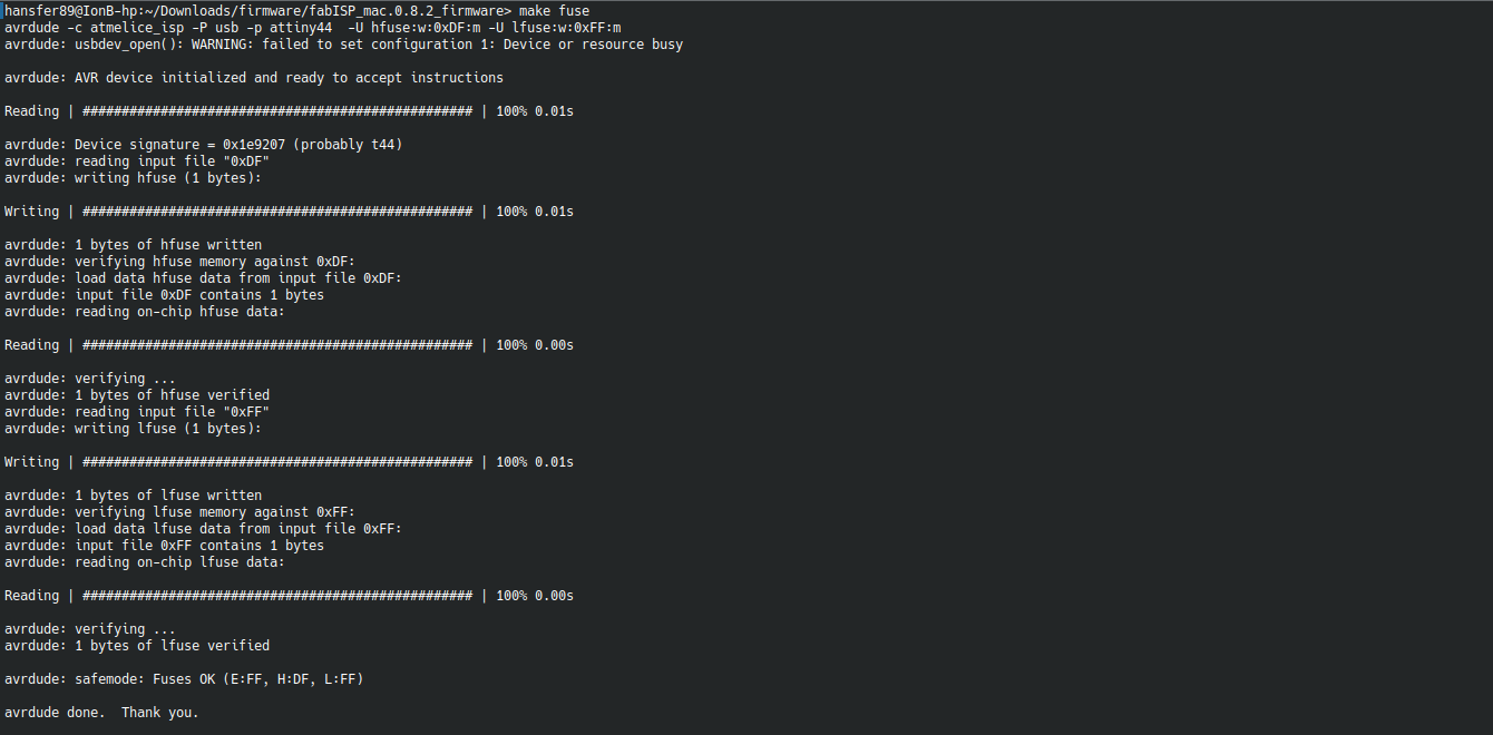
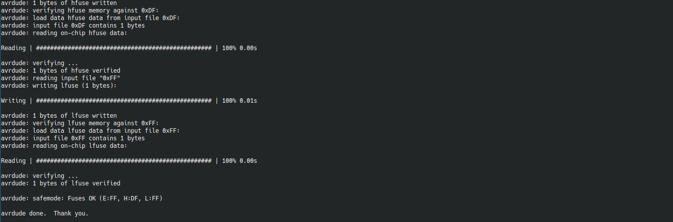
*  Make Fuse
*
Make Fuse
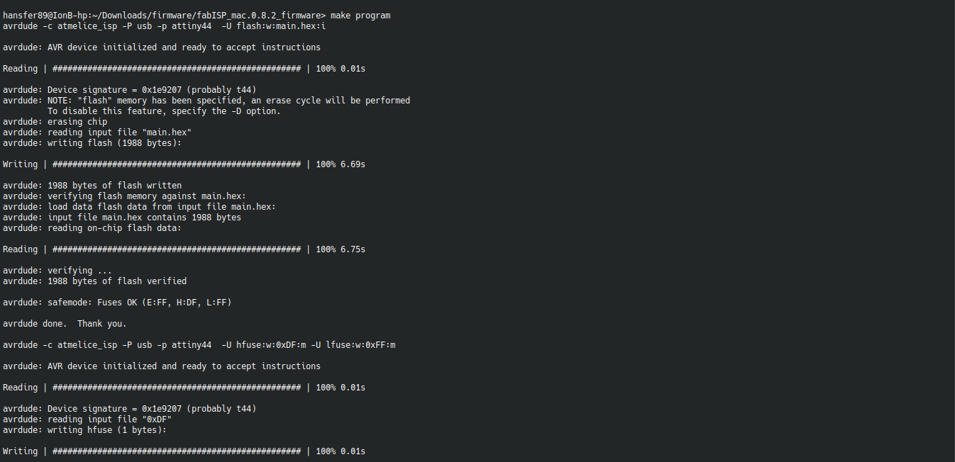
*  Make Program I
*
Make Program I
*  Make Programa II
*
Make Programa II
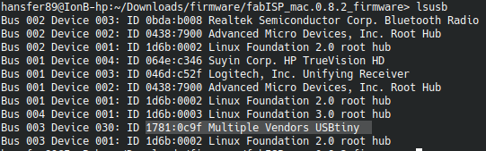
*  Isusb
*
Isusb
* 
And I needed to remove the solder from the zero resistor and from the bridge