
Our inspiration comes from a problem we faced when we were at week 6, doing the 3d printing and scanning, we realized how useful it would be to have a 3d scanning “station” , something that helps us to move our camera in order to take pictures, film or scan an object without doing it by hand.
Taking timing and resources into consideration, we decided to build a machine that allows us to film and take immersive 360 pictures using a cellphone camera with the possibility to also become a scanning support in the near future.
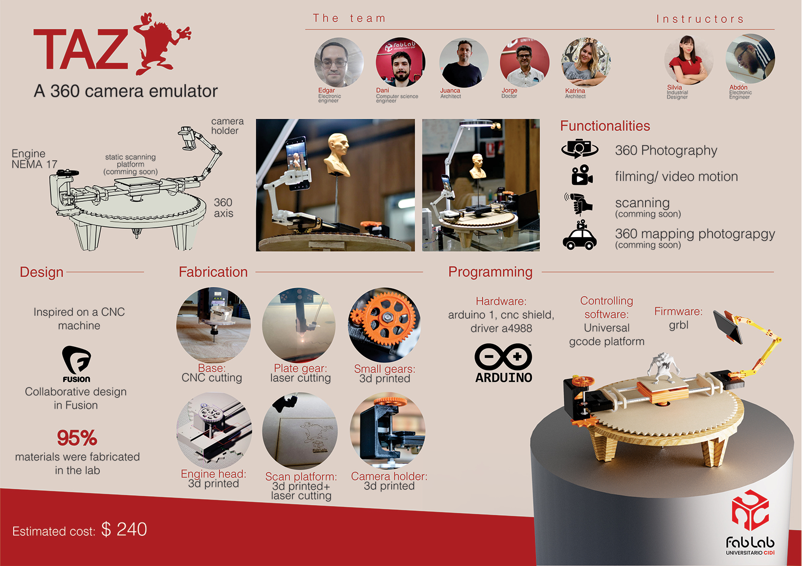
In short, the “Demoño de Taz” is an automated mobile camera holder for 360 immersive photography, filming and scanning (coming soon)
At the beginning, we just wanted to have a machine with only lateral mobility (one axis) and we thought about this machine to be like a CNC but with a camera holder instead of a spindle and mill. But we started to be more ambitious so the idea of having a circular plate came up.
Basically we replaced the regular rectangle cam of the CNC for a circle “plate” that would be the axis for the camera holder in order to have 360 mobility.
And thinking especially about the time limitation we decided to design using laser cutting and machining as much as possible.
We used Fusion collaboratively in order to divide the work and add comments and answer questions together.
We used laser cutting to build the main circular plate which needed to be a large “gear” and we decided to use MDF and laser cutting because of its precision.
We used CNC cutting to build the base for the machine because we wanted to have a more robust and strong structure
We printed smaller gears, a head for the engine, a main rotation box, a bow for the pcb and a camera holder using 3d printing technologies. We use this technique in order to personalize designs and achieve precision.
-
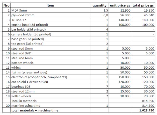
We decided to buy the following items:
- bearings, screws, steel rods and 2 roller wheels.
We start to produce our own arduino to programming but we didn’t finish it so at the end we decided to buy a cnc shield + driver a4988
We used a NEMA 17 to move the gears alongside the circle plate in order to rotate a bar containing a camera holder on one of its ends. This allows the camera to move in 360 degrees and the camera holder allows pointing the camera out or inside the circle, if it is pointed out it is used for filming and photography, on the other hand, if it is used pointed inward is to be used as a scanning camera.
The entire bar contains the NEMA 17 on one end and the camera holder on the opposite, this helps to balance the weight between the camera and the engine. in the center of the bar there is a steel rod that serves as a support for the object to be scanned, and this platform does not move because the camera is the one that moves around it
- Add the grbl library in arduino one
-
Go to examples/grbl/ select the correct programmer and port, compile and run
-
this is the code we used:
This sketch compiles and uploads Grbl to your 328p-based Arduino!
To use:
- First make sure you have imported Grbl source code into your Arduino
IDE. There are details on our Github website on how to do this.
- Select your Arduino Board and Serial Port in the Tools drop-down menu.
NOTE: Grbl only officially supports 328p-based Arduinos, like the Uno.
Using other boards will likely not work!
- Then just click 'Upload'. That's it!
For advanced users:
If you'd like to see what else Grbl can do, there are some additional
options for customization and features you can enable or disable.
Navigate your file system to where the Arduino IDE has stored the Grbl
source code files, open the 'config.h' file in your favorite text
editor. Inside are dozens of feature descriptions and #defines. Simply
comment or uncomment the #defines or alter their assigned values, save
your changes, and then click 'Upload' here.
Copyright (c) 2015 Sungeun K. Jeon
Released under the MIT-license. See license.txt for details.
***********************************************************************/ #include < grbl.h>
// Do not alter this file!
- Install the software universal gcode platform that allows to control the movement of the machine through the code we sent to it
- Select Firmware GRBL, the port where you plug the pcb in and the bauds
- Then, connect
- Once connected you can move with the arrows and also send commands in gcode from the console
- example of how to send a command to move to position 150 (of 360)
- Yo can also load or write a gcode file and execute with these buttons
This is the list of materials used to produce the machine, It cost aproximately 240 USD
Students and Instructors

Edgar: Team leader, he is an electronic engineer and he has experience in building machines, so he was the brain of the operation! He was in charge of the main design and programming of the machine. Also collaborated with some 3d printings in his own lab (where he works)
Dani: He is a computer science engineer and was the right hand of the team leader, Edgar. He was mainly in charge of the design and fabrication of all the gears and the base structure of the machine. Also was in charge of compiling photos and videos and made the videos we are seeing in this site.
Juanca: He is an architect and was in charge of design and production of the head for the engine, also the platform for the object to be scanned and the box and mechanism to put the arduinos pcb and wiring into the machine. He also encouraged us to not just leave the machine as a filming and photography device but also as a scanner support.
Jorge: He is a Doctor and he was in charge of designing, milling and soldering the pcb for the machine. Also helped with logistics and fabrication helping Edgar and Dani.
Katrina: She is an architect and she was in charge of designing and printing the camera holder at the end bar opposite to the engine. Also was in charge of writing this documentation and designing the final poster.
Silvia: She is an Industrial designer and she is our main instructor for the academy. She was leading us and also helping with the design, fabrication and documentation along these weeks
Abdon: He is an electronic engineer and he is also our instructor, he was accompanying us, giving advice, instructions and tips. Also was helping with the programming and ideas to debugging and problem solving.

A machine that allows us to film and take immersive 360 pictures using a cellphone camera with the possibility to also become a scanning support in the near future.
-
Size50x70x40 cm
-
FirmwareGRBL
-
Hardware:Arduino 1
Cnc shield
Driver a4988 -
Software:Universal
gcode platform