Final Project
Made a separate Final Project page that briefly summarises your project
- Made a separate Final Project page that briefly summarises your project:

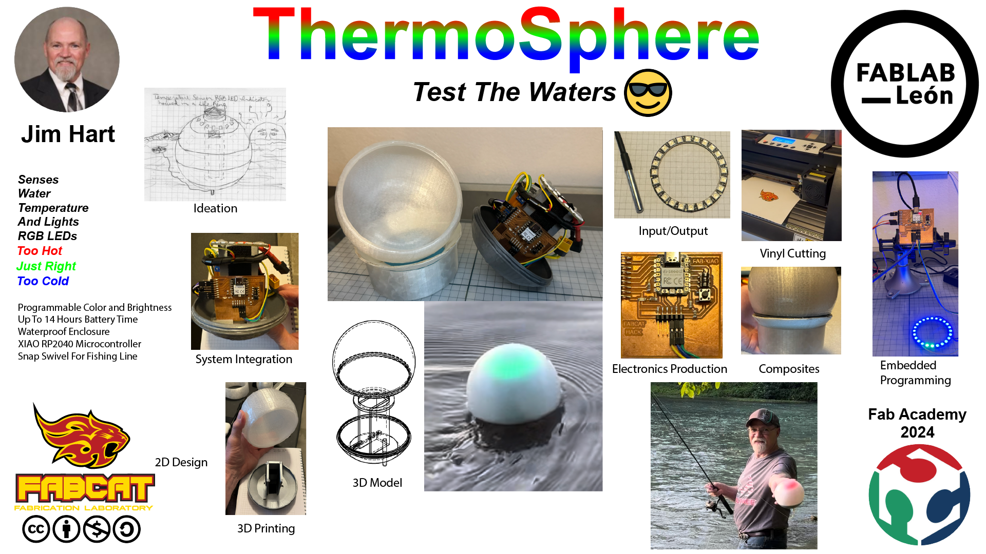
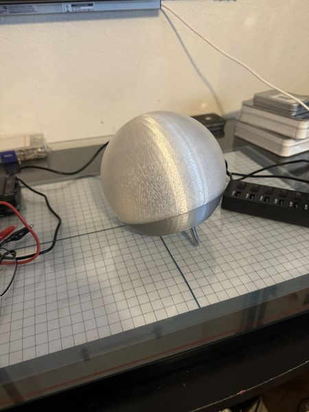
The ThermoSphere is a floating device designed to measure the temperature of water and light RGB LEDs in a NeoPixel Ring. The original concept was to inform sailors of the temperature of the water in case the boat they are in capsizes. There are many potential use cases, but one I will focus on is related to fishing. The angler would like to be informed of the temperature of water since water temperature can change the feeding habit of the fish.
I have redesigned and 3D printed the Sensor Globe and Electronics Housing as the waterproof enclosure. The electronics are modularly designed with the FABCAT Board using the XIAO RP2040 as the microcontroller, the Power Supply Module using a LM1117 5V voltage regulator to maintain 5 volts for the FABCAT Board from the 7.4V 1500mAh 2s Li-Po Battery, the Gikfun DS18B20 Temperature Sensor, and the Adafruit 100226 24 RGB Neopixel LED Ring, as well as screw terminals and wiring.
The ThermoSphere has a snap swivel on the bottom to allow anglers to attach a fishing line for ease of deployment and retrieval. The temperature settings for color and brightness are adjustable through MicroPython programming using the USB-C connection on the FABCAT Board. The ThermoSphere had an epoxy coating and beeswax waterproofing to keep water away from the electronics during use.
Made your slide> 1920 x 1080 pixels with your name, project name, Fab Lab name, a photo/render/sketch of your project, a brief description of what your project is/does
- Made your slide> 1920 x 1080 pixels with your name, project name, Fab Lab name, a photo/render/sketch of your project, a brief description of what your project is/does:
Made a ~1 minute (10MB/1080p) video of you explaining your project
- Made a ~1 minute (10MB/1080p) video of you explaining your project:
What does it do?
- What does it do?
The ThermoSphere is a battery powered programmable waterproof temperature sensor. The Use Case is for trout fishing since trout feed at temperatures less than 68 degrees. The temperature sensor is a DS18B20 read by the XIAO RP2040 and outputs to a NeoPixel Ring to give an “at a glance” indication of water temperature.
Who’s done what beforehand?
- Who’s done what beforehand?
Acknowledged work done by others
- Acknowledged work done by others:
Inspiration
-
The original Final Project consisted of many projects. With guidance from my Instructors, Pablo Nunez and Adrian Torres, as well as Rico Kanthatham the scope needs to be reduced. Content related to Managing Projects as presented by Norella Coronell and May El-Dardiry will be listed on this Final Project page.
-
For Electronics Design I will need to make a board to host the microcontroller and receive the inputs as well as send the outputs. I propose to use the Fab-XIAO with a minor FABCAT Hack that consists of a pull-up resistor for the temperature sensor and rerouting of signal lines and power lines. Adrian, thank you for your excellent guidance and inspiration!
-
During my research I had a lot of help from my Instructors to guide me toward a solution. Adrian Torres recommended this Weather Station Buoy by Luis Diaz-Faes for inspiration. Rico Kanthatham inspired me with his Final Project. Rico also gave my guidance to another student from his Fab Lab, Jun Kawahara Through the Weather Station Buoy, I found additional inspiration for something more within my grasp with a smaller Smart Buoy.
Digital Design
-
The ThermoSphere was in my mind’s eye, but making/designing the globe was a challenge. So I used the internet to search in Thingiverse.com for “sphere clear pla” because that was what I wanted and the material I intended to use. I got some really cool results, but the best was the Phillips Hue Globe Diffuser. THAT IS IT! I can work with that! So I researched a little bit. Turns out the author, ApatheticEnthusiasts (Robert Barton), did some research too. He summarized as, “This is a remix using parts from two things: Bottom and Top.” Eventually, I ended up with Fusion 360 design files from Abditus2 called the Sensor Sphere Box and the method of designing exactly what I need.
-
I documented how I designed a logo for my new Personal Fab Lab. As a background story, the logo for the GOCAT Fab Lab was designed by Tom Wood for me when I first built the GOCAT Fab Lab. He said I needed a “kickass cat” for my lab and he did not disappoint. As you may/or may not know, I left the University so I could continue/complete my studies in Fab Academy, so the GOCAT is no longer a “going concern”, but the “cat” who made the GOCAT Fab Lab is still going :) So you will get to see how I made some changes to make a new logo.
-
I wanted to use the FireCat, but the name had to change. My original attraction to Fab Academy was the idea of building a boat using digital fabrication. Soooo, I thought of FABCAT and made a domain name to match. As a disclaimer, I discovered that there is another FabCat Fab Lab, but they are located in Catalonia and I am located in the United States; hence the domain name FABCAT.us. We are not competitors and have not met, but I hope we meet some day. My Fab Lab is focused on boats and their automation, so the name FABCAT is an acronymn for Fab Academy Boat-Centered Automation Technology in the USA.
What did you design?
- What did you design?
I designed the full housing structure starting with the “Sensor Sphere Box” made by Abditus2. I focused on the base of the Sphere and designed what I call the Electronics Housing. Further, I designed a power supply board and designed the FABCAT PCB based on the FAB-XIAO design. The electronics to detect temperature and output to a RGB LED ring were designed as well. I also designed the presentation slide with 2D design for FABCAT.
What materials and components were used?
- What materials and components were used?
The waterproof Sensor Globe and Electronics Housing:
- 3D PLA filament
- polyester film for the decal
- epoxy resin
- waterproofing beeswax
- snap swivel
The Electronics:
- PCB FR-1
- LiPo Batteries
- RGB LED Ring
- DS18B20 Temperature Sensor
- XIAO RP2040 microcontroller
- discrete smd components
- connectors and wiring
- screw terminal module
- hook and loop material for PCB mounting
Where did they come from?:
- Where did they come from?:
The 3D PLA filament came from Amazon and Prusa Research. The polyester film for the decal and the epoxy resin came from Amazon.The waterproofing beeswax and snap swivel came from local suppliers. The electronics came from Amazon and Digikey.
How much did they cost?:
- How much did they cost?:
Included the BOM (Bill of Materials) for your project
- Included the BOM (Bill of Materials) for your project:
| ThermoSphere | Where to buy? | Amount | Price | Total Price |
|---|---|---|---|---|
| 3D PLA filament | Amazon/Prusa Research | 0.1 | 23.99 | $2.40 |
| Polyester film for the decal | Amazon | 0.25 | 22.84 | $5.71 |
| Epoxy resin | Amazon | 0.1 | 59.99 | $6.00 |
| 09-00500 DACRON FABRIC 605 2.97 OZ | AirCraftSpruce.com | 1 | 4.35 | $4.35 |
| Waterproofing beeswax | Locally | 0.1 | 1.97 | $0.20 |
| Snap swivel | Locally | 1 | 0.48 | $0.48 |
| Gikfun DS18B20 Temperature Sensor | Amazon | 1 | 2.49 | $2.49 |
| Adafruit 100226 24 RGB Neopixel LED Ring | Amazon | 1 | 20.93 | $20.93 |
| CNHL 7.4V 1500mAh 2s Li-Po Battery | Amazon | 1 | 13.28 | $13.28 |
| LM1117 5V Voltage Regulator | Digikey | 1 | 0.48 | $0.48 |
| PCB Copper Clad Board uxcell 7X10cm | Amazon | 2 | 0.949 | $1.90 |
| R_1206 | Digikey | 4 | 0.05 | $0.20 |
| LEDFAB1206 | Digikey | 1 | 0.23 | $0.23 |
| Button_Omron_B3SN_6.0x6.0mm | Digikey | 1 | 1 | $1.00 |
| Module_XIAO-RP2040 | Digikey | 1 | 4.68 | $4.68 |
| Conn_PinHeader_1x06_P2.54mm_Horizontal_SMD | Digikey | 1 | 0.6 | $0.60 |
| Conn_PinHeader_1x09_P2.54mm_Horizontal_SMD | Digikey | 1 | 0.9 | $0.90 |
| Conn_PinHeader_2x03_P2.54mm_Vertical_SMD | Digikey | 1 | 0.84 | $0.84 |
| Screw terminal module | Seeed Studio | 2 | 0.15 | $0.30 |
| Capacitors | Digikey | 2 | 0.22 | $0.44 |
| Hook and Loop Tape | Amazon | 0.1 | 17.99 | $1.80 |
| Total | $69.20 |
What parts and systems were made?:
-
What parts and systems were made?:
-
ThermoSphere Globe and Electronics Housing - Print Time: 24.5 hrs + 11.5 hrs = 36 hrs
- Thermosphere Stand - Print Time: 4.5 hrs + 5.5 hrs + 2.5 hrs + 2 hrs = 14.5 hrs
- Electronics - PCB Time: 15 hrs + 18 hrs = 33 hrs
- Assembly - Time: 24 hrs
- Total Time (without breaks or errors :) - 107.5 hrs or 13.5 days or approximately 2 weeks of 8 hr days.
What processes will be used?:
- What processes were used?:
Computer-aided design will be used to 2D design the form of the ThermoSphere Stand and 3D design of the ThermoSphere Globe and Electronics Housing. Computer-controlled cutting will be used to laser cut the template for cutting the fabric with a hot cutter and vinyl cutting the decal. Electronics design and production will be used to fabricate the FABCAT PCB for temperature sensing input and RGB LED output as well as the Power Supply Module for utilizing a 7.4V Li-Po Battery. Embedded microcontroller interfacing and programming will be used for these circuits to adjust temperature settings and RGB LED brightness. 3D printing will be used for the ThermoSphere Globe, Electronics Housing and Stand. To stablize the ThermoSphere during programming, a ring of Dacron and Epoxy made as a composite will be placed in the ThermoSphere Stand. The assembly and integration of the subsystems will result in a battery powered waterborne ThermoSphere that senses temperature and informs the user of water temperature with RGB LEDs.
What questions were answered?:
- What questions were answered?:
Is the ThermoSphere going to require a floatation device to stay above the surface of water? I did a calculation to determine whether the ThermoSphere would float using the concept of buoancy. I the weight of the object is less than the weight of the water it displaces when in water, it will float. IT turned out that only 1/3 of the ThermoSphere will be under water. I still used the life ring to be safe on the first deployment.
Is the temperature sensing sensitive enough to detect small changes in temperature over a short distance? It was sensitive enough, but I had the delay time between readings set for 5 seconds; this made the transition slower. Once, I set the delay to 0.5 seconds, it was very responsive.
What worked? What didn’t?
- What worked? What didn’t?:
As was mentioned in the previous paragraph, I wasn’t sure of the buoancy of the ThermoSphere, so I used the life ring and a safety net to hold it. Although the light wasn’t bright enough due to sunlight, the net blocked it further. Since the ThermoSphere floated wonderfully, I retire the life ring and net and deployed it at the end of fishing line. I worked perfectly.
The timing was slow, so that needed to be adjusted. Also when the Stand Adapter was made from composite, the epoxy resin joined the support ring to the inner mold/form. In order to obtain the composite, I had to break the mold, but the composite came out fine.
How was it evaluated?
- Does it float without leakage? Yes, after all of the testing, there was no water in the enclosure!
- Does it provide water temperature indication? Yes, the temperature variations were displayed correctly by the RGB LED Ring!
- Does it provide a visual indication of water temperature? Yes, Red for the Warm Fork Spring River, Green for the Spring River, and Blue for the Mammoth Spring water!
- The project will acheive its objective if it can show me the best water to fish for trout. This objective was achieved and showed that the Warm Fork Spring River would not be the best place to fish for trout, but the Spring River and Mammoth Spring below the dam would be perfect!
What are the implications?
- What are the implications?:
In order to test the ThermoSphere, I obtained a fishing license even though I wasn’t technically fishing. This was to prevent a violation/ticket from the Game and Fish Warden. I thought it would be prudent. However, now that I have a license and will have some time off after Fab Academy, I plan to do more fishing :)
The ThermoSphere can be upgraded by small change in the design to have an o-ring instead of beeswax and lanolin. Additionally, I can modify the FABCAT PCB to hold different XIAO boards including the ESP32C6 for wireless communication.
The introduction to the design and fabrication of the ThermoSphere provides a valuable skillset to be used in building boats and submarines.
Fabrication Process
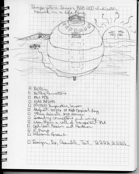
- Design Solid Structure of Idea
First, I need to design my own board that will accomplish the concept of this Final Project while keeping it simple ;) I will use the XIAO RP2040 on a board that provides power from an external LiPo battery, takes an input from a temperature sensor, and provide an output from a RGB LED.
Second, I need to design a sphere that will contain the electronics while keeping them safe from the water environment they will be in.
Finally, I will need to design a floatation device that keeps the sphere afloat while making it recoverable. So, here is a sketch of my Final Project at this point.
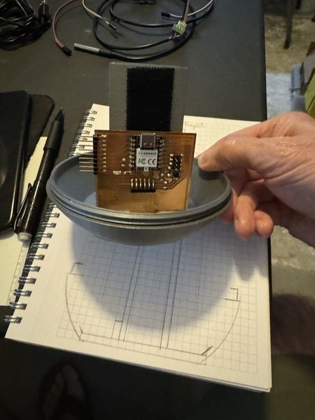
At the end of this iteration, I prototyped an Output Device for the Final Project. This allowed me to Ideate about the Final Project board design and the connectors I should use.
This pushed me forward to prototyping for the Input Device for the Final Project.
In order to make this happen, I will need to design a board to host the microcontroller and the connections necessary to receive the input and provide the appropriate output. Using the above list of materials, I have made a sketch of the initial concept of the board design.
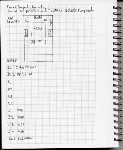
This is an update of the Final Project Board prior to stuffing.
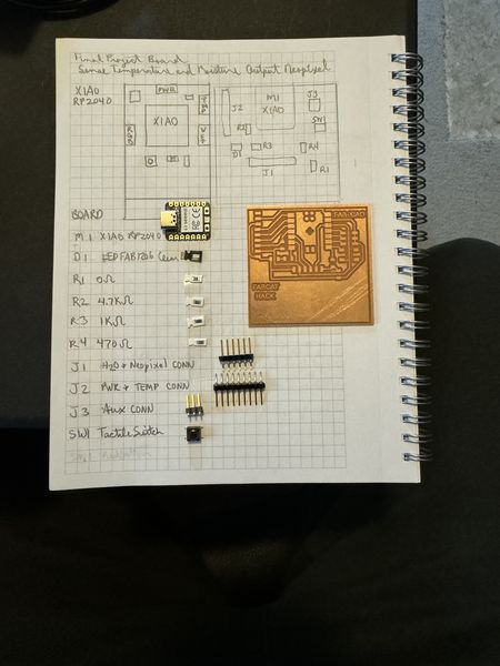
You can read more about this on the Electronics Design page.
In parallel with the conceptualizing of the board, I have also been thinking about the global structure of this project. I searched for an example of the globe I envisioned while I ordered a life ring to hold it in the center…I’m sure you noticed the life ring in the W6 User Empathy section ;) The life ring was in my mind’s eye, but making/designing the globe was a challenge. So I used the internet to search in Thingiverse.com for “sphere clear pla” because that was what I wanted and the material I intended to use. I got some really cool results, but the best was the Phillips Hue Globe Diffuser. THAT IS IT! I can work with that! So I researched a little bit. Turns out the author, ApatheticEnthusiasts (Robert Barton), did some research too. He summarized as, “This is a remix using parts from two things: Bottom and Top.” Eventually, I ended up with Fusion 360 design files from Abditus2 called the Sensor Sphere Box and the method of designing exactly what I need.
MAJOR NOTE: I did not design this globe from scratch. Let me reiterate, this design was obtained from Thingiverse.com and I was able to download the Fusion 360 files that Abditus2 provided back in December 04, 2018. I am able to manipulate the files and models to make the transformation I need. I did not use all of the models, just the plain sphere and the base unit. I will document the changes that I made so you can see what I have done.
This is the image of the design process, complete with the steps in Fusion 360.
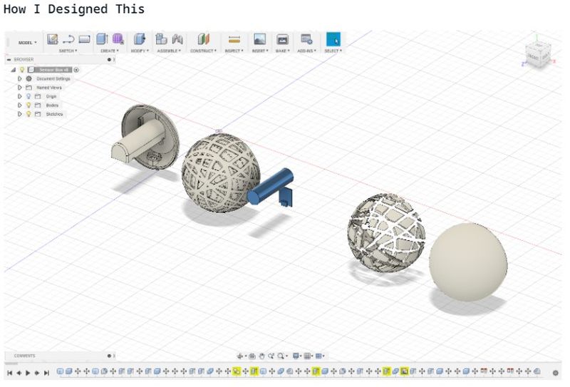
This is the internal design that really fits for what I am trying to do.
So I brought the file into Fusion 360, isolated the parts I was interested in, added a torus to represent the life ring, and I am well on my way to saving this Final Project :) More to follow!
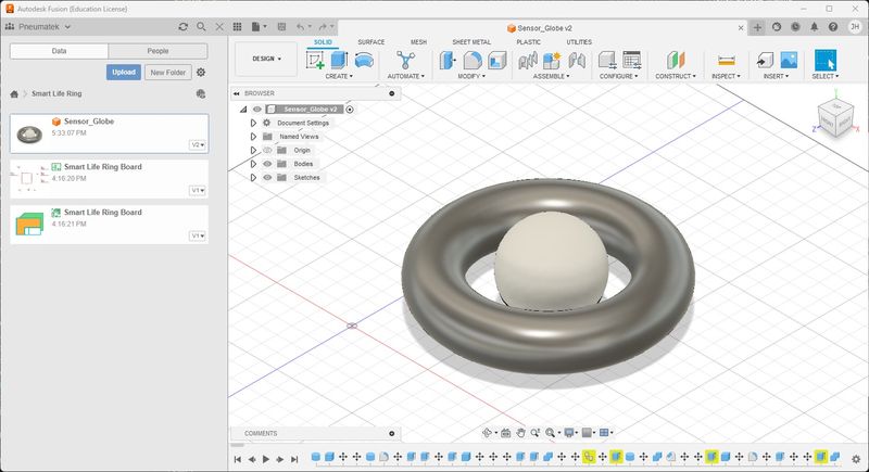
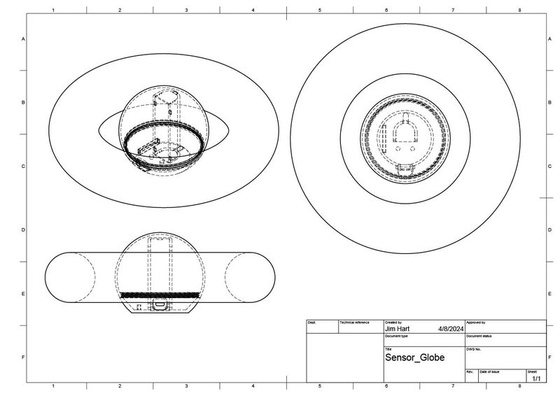
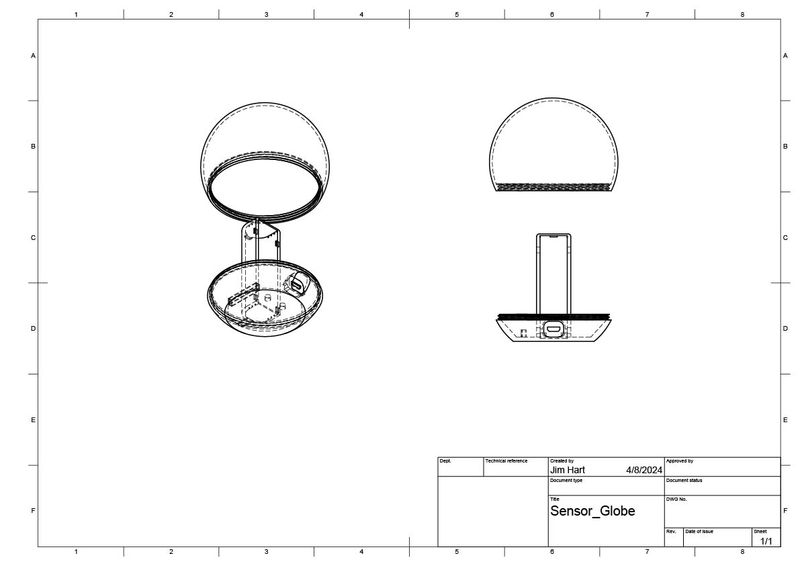
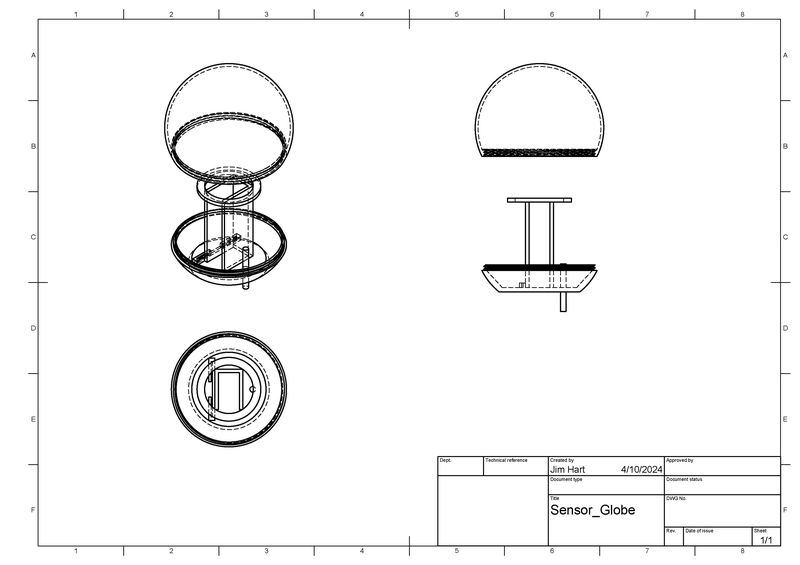
These are the drawings I made in Fusion 360. It took some time to figure out, but MAN, this is so cool!!!
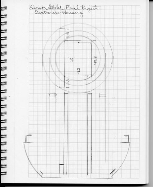
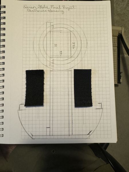
This is a sketch of the Electronics Housing (Globe Base) and what I intended to do with the provided model in order to house the internals of the sensor globe. The 35mm x 22mm rectangle is for the Battery Holder and the long and narrow rectangle is for the FABCAT Board Holder. The inner circle is the NeoPixel Ring.
I have modified the Electronics Housing to be my own. I really appreciate the starting point from the Phillips Hue Globe Diffuser who pointed me to Abditus2. I couldn’t have done it alone! I made it simple; Battery Holder, FABCAT Board Holder, Temperature Sensor Mount, and NeoPixel Ring Mount. If necessary, I will make separate mounts for the Screw Terminal Mounts, but I think they will be fine secured to the Battery Holder with hot glue and hook and latch material.
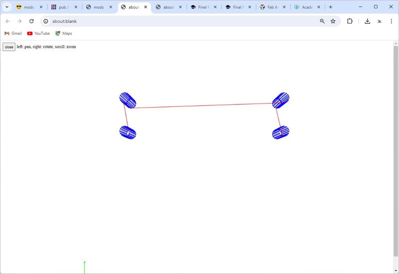
I will put a video here so you can see how I made the transformation. In a nutshell, I removed the internals of Abditus2’s model and replaced them with my own to fit the internal components I will be using. I also modelled a NeoPixel Ring so I could figure out what height it had to be at in my new design. This was probably the coolest thing about it; I literally moved the parts around as if I was using my hands and it really helped with visualizing what I was trying to do. Lastly, I made a hole in the bottom for the temperature sensor and then extruded it so you could see what it would look like. Everything is to scale for the components I will be using; Battery, FABCAT Board, Temperature Sensor, and NeoPixel Ring. I measured them and used the dimensions is the designing process. Fab Academy has really strengthened me in the 2D and 3D design area because I have to do this to realize the full potential of digital fabrication. I’m getting there, but slower than most. Accomplishing what I am about to show you was challenging for me, but I feel like I have accomplished a major milestone in my modelling journey. I hope this helps some students in the future. It was tricky to select every surface before deleting things; sometimes the whole part disappeared and I had to rewind. I hope you enjoy the show ;)
My intention is to add to this Final Project in spirals with the time I have, so it will need to be a flexible/temporary design. Having a threaded globe allows me to make changes while making the design as simple as possible. My plan is to secure the components in the Electronics Housing with hot glue as well as hook and latch material; this allows for changing things as the project develops in spirals without having to reprint the Electronic Housing (Globe Base). This will allow me to fasten additional boards to the Battery Holder on the outside as well as fasten the battery to the inside of the Battery Holder. This design will also allow recharging the battery without having potential leaks through external connectors; in other words, easily remove the battery for recharging.
3D Printing
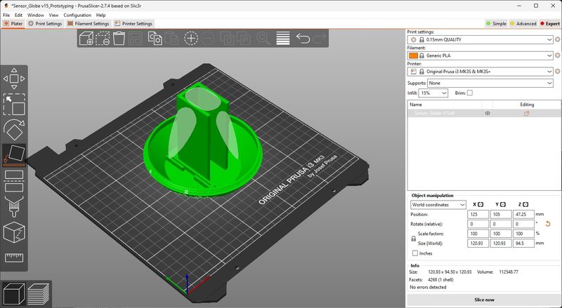
The 3D printing required exporting the model designed in Fusion 360 to a STL format, then importing it into PrusaSlicer. Since this has been practiced many times before, I was fairly comfortable with the process. I still learned a bit more. When I imported the STL into PrusaSlicer, the model was on its side.
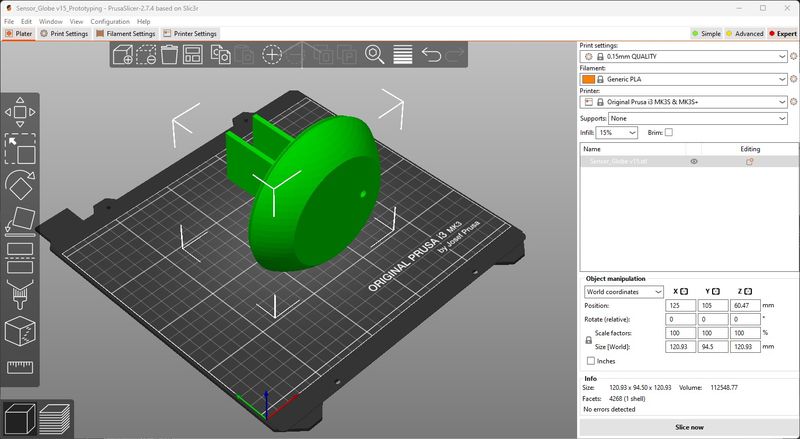
I used the Rotate tool and the widget to rotate the model as close to 90 degrees as I could get it. There is not a method to type the value in, so using the mouse was the best I could do. I got it to 90.03 and thought that was good enough.
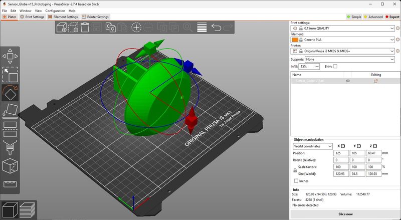
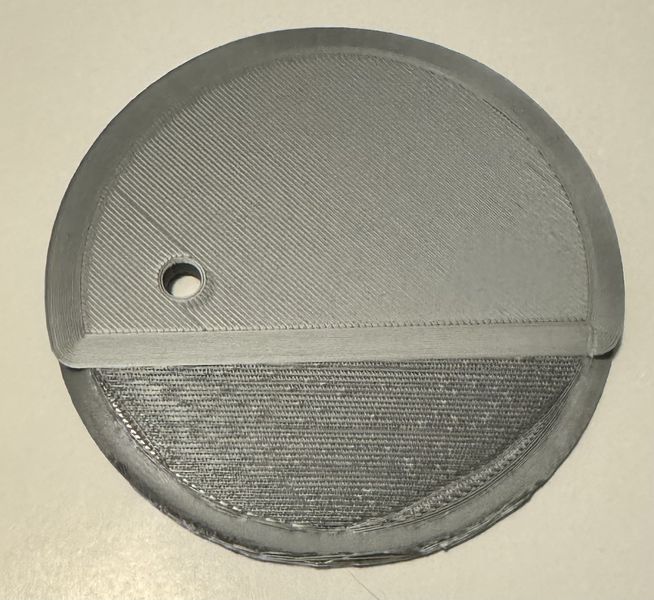
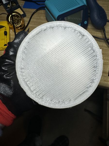
The small difference caused the model to be slightly off the plane and made a separation in the base. This was puzzling to me, but I went with it and figured it would work out. I exported the g-code and tried to print. This is what the bottom looked like.
And this is the top.
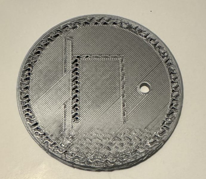
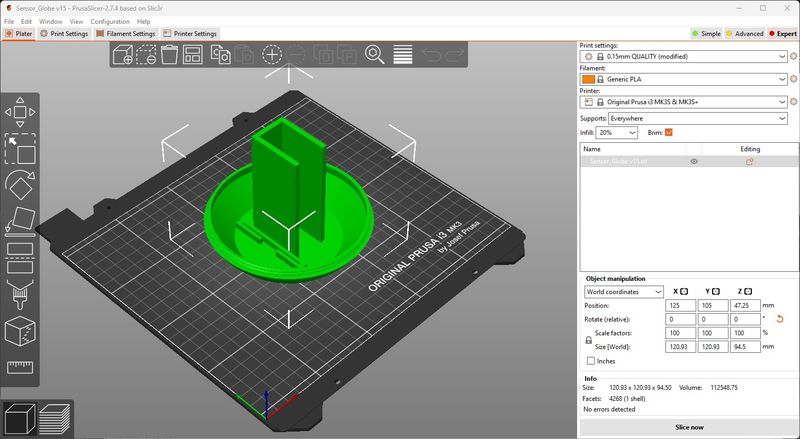
The edge lifted up so much that it caused the first crash I have had on my Prusa 3D printer. I stopped the print and went back to the design. The design was still the same and I changed the orientation of one of the models thinking that was the problem. It still came into PrusaSlicer on its side. But this time I decided to use “Place on face”.
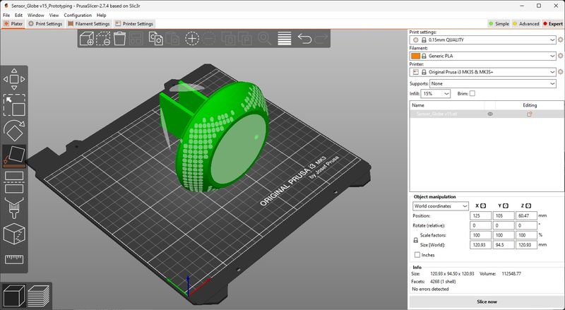
As soon as I clicked on the base face, it rotated to the perfect position.
I exported the model with the same settings, but this time I added supports everywhere. (Just to be safe :)
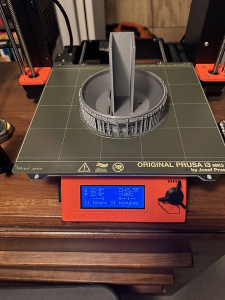
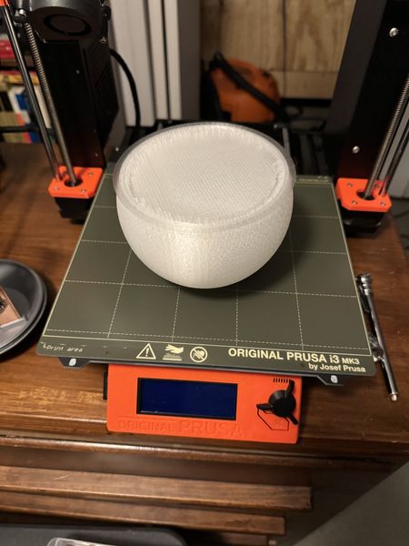
The print job took 11.5 hours, but it was worth the wait.
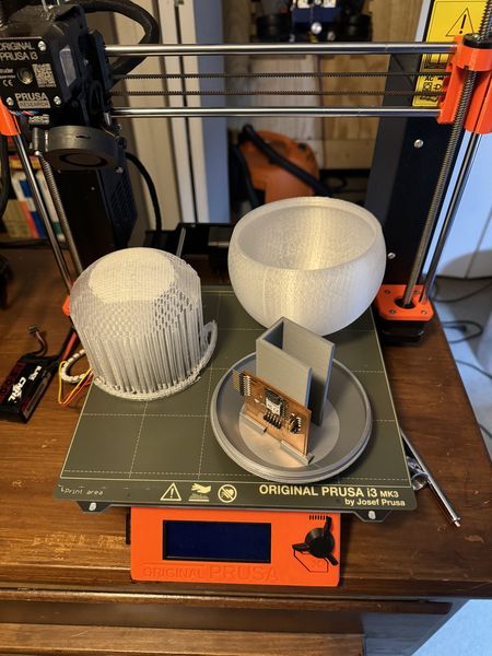
I wanted to make sure the prototype had the proper dimensions.
Perfect fit! Now for the post-processing :)
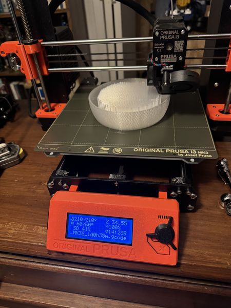
The next print job was the globe. I imported it the same as the Electronics Housing. I oriented it in the upward position and chose supports everywhere. I exported the g-code and it said it would take 24.5 hours. I started it Friday night and on Saturday morning I decided to listen to it while I probed analog and digital devices. What an enjoyable experience :) This is what I found in the morning.
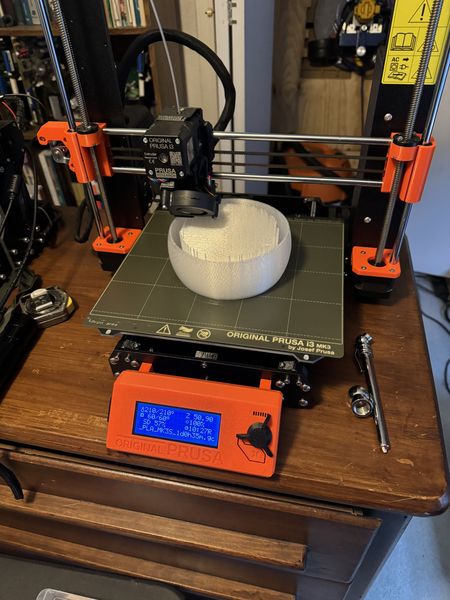
A little bit later. Looking pretty cool!
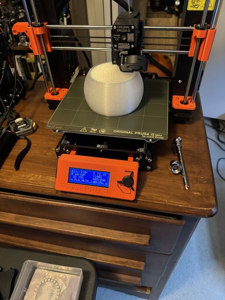
Almost there!
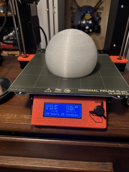
Would you look at that!
Post-processing was a very rewarding experience. Here is the globe parted from the 3D printer.
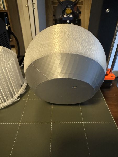
This after I cut around the edges.
I pulled the support out of the globe and here is a good picture.
Perfect fit!
In addition to the 3D print jobs shown here, there were other print jobs that happened for the production of the Stand and Stand Adapter in Wildcard Week.
Electronics Design and Production
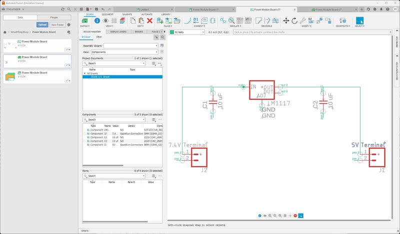
While I was waiting on the print job, I worked on designing the Power Supply Module… This seemed like a simple task since I had designed more complex boards. To be safe, I did some research on the Internet. I found some good help from LM1117 Linear Voltage Regulator by AaronPrice. I didn’t need a variable power supply, but this was a nice Instructable. Since there were so few parts, I decided to design in the Fusion 360 app. This was no small feat, but it all turned out well. This is my schematic.
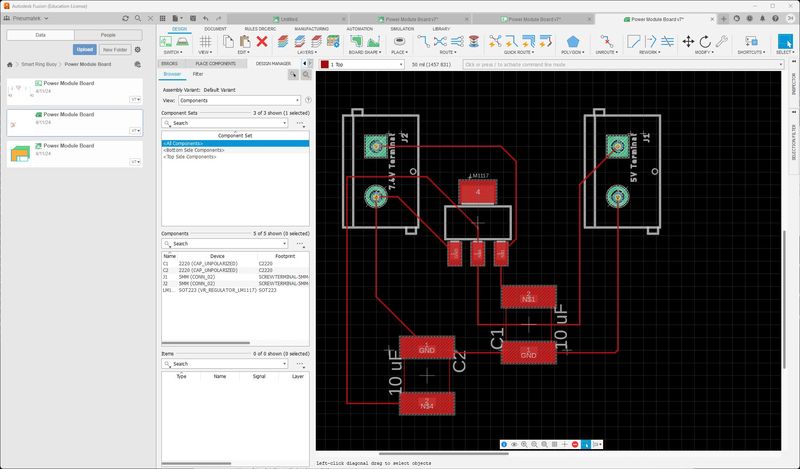
This is my board.
I used my documentation from Electronics Design to refresh my memory.
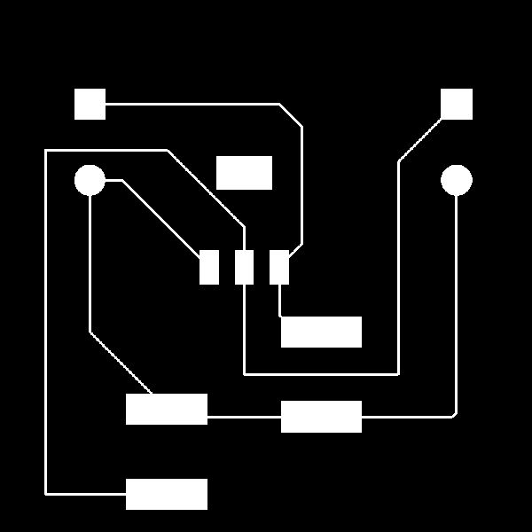
First, I save the Fusion 360 project as an Eagle 9.x format as I described in Electronics Design and exported the trace image, drills, and border for GIMP. After cropping them to the proper size, this is what I sent to mods.
The trace image.
Drill holes for the through-hole screw terminals.

And border to cut out the board.

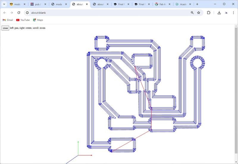
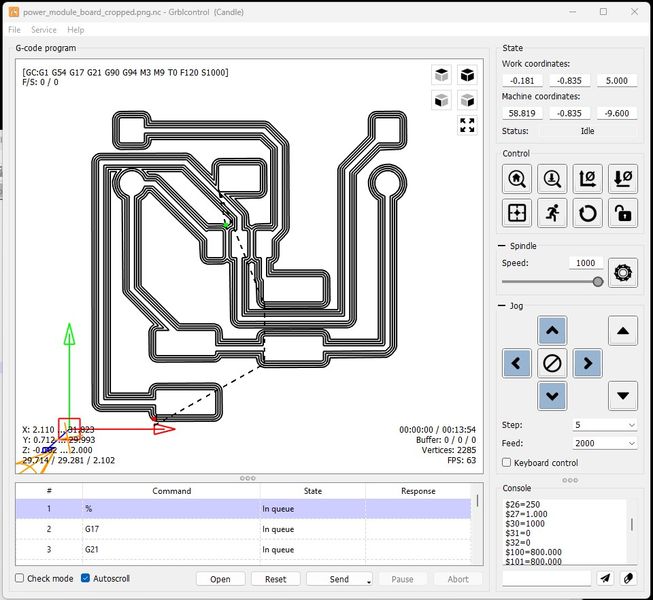
I used mods old index to generate the G-code from mill 2D PCB png.
The trace image.
Drill holes for the through-hole screw terminals.
And border to cut out the board.

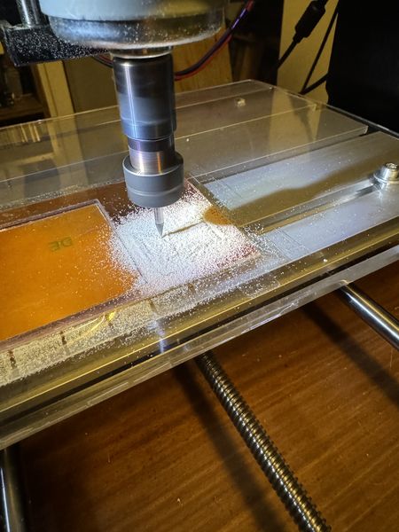
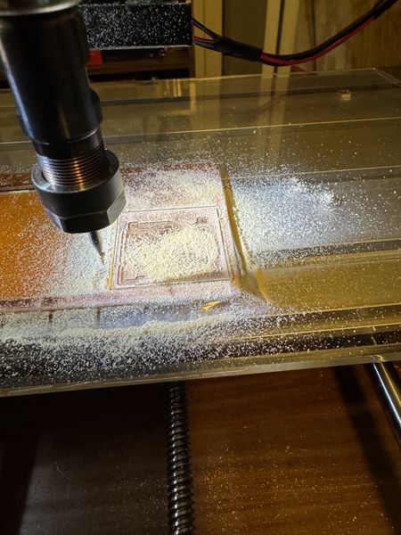
Now I need to mill the Power Supply Module board. Thankfully, I already had my FR-1 mounted from my last job. I pressed down on the material to make the tape stick again and I taped around the edges for extra protection. I only had 37mm wide material left and the board required just that. I wanted to run the traces first to be sure I had enough room.
First, I raised the endmill and zeroed Z to cut air and figure out if it would fit. It was just big enough :)
Then I drilled the holes using this g-code.
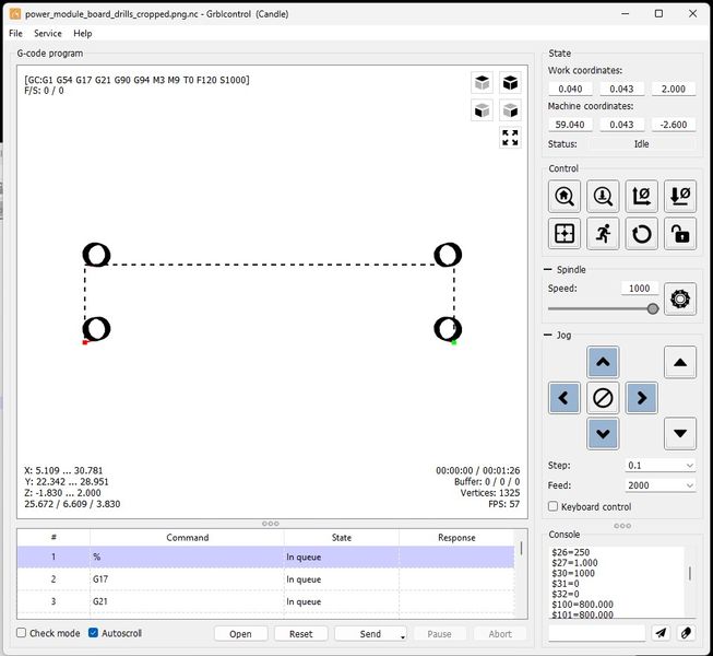
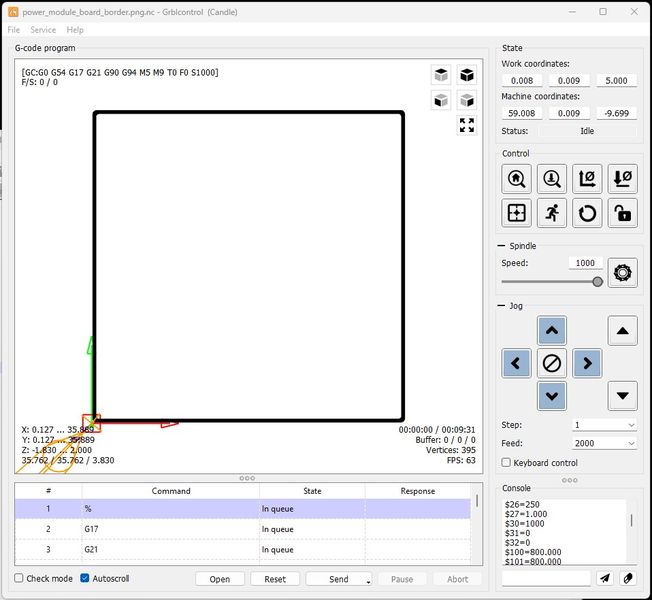
Again, I cut air, and I am so glad I did. When I designed the board I used vias to make the holes. I had never designed through-holes, so this was a first. I’m glad I was cautious. Although they were in the right place, they were way too big. My solution was to operate the CNC using the Candle interface to position the endmill (using the g-code generated image). I changed the endmill to 1mm since the posts on the screw terminals were 0.95mm and drilled each hole to a depth of 1.8mm at 0.1mm increments. Kind of a hack, but it worked beautifully. The posts were 5mm apart and it was so cool to use the machine with precision.
This is the border for cutting out the board.
I ran the jog, but I was a little nervous about the tape holding, so I kept my finger on the mouse to abort if necessary. I’m glad I did, because the board popped up a little on the last round and I aborted. It made it successfully.
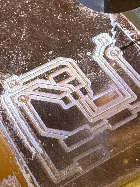
I cleaned the board to prepare it for stuffing. The traces were real thin, so I was nervous, but they all survived.
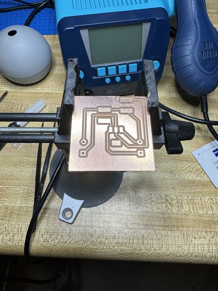
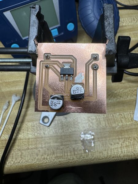
This is the electronics side stuffed. The capacitors were a surprise. I thought I was using 1206, but the pads were huge and too far apart. I had selected the wrong capacitor footprint in Fusion 360. It was from the Fab inventory, but not the one I wanted. All I had in this size footprint was a 100uF electrolytic capacitor. I did some research and found someone who used a 100uF electrolytic capacitor for a LM1117 circuit and it worked just fine, so I did the same. I’ll tell you what; these are not fun to solder. The base is plastic and it melts when touched with the solder iron. A very delicate process! But I got it done; although it was a little messy :)
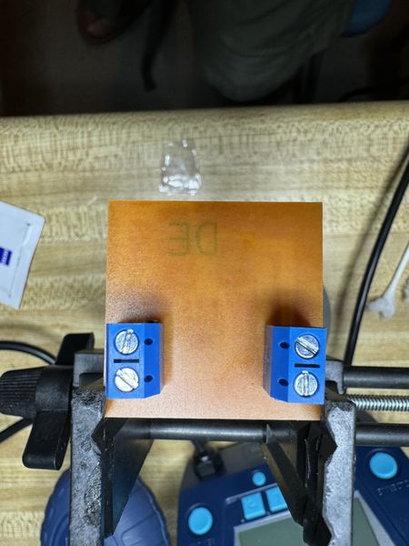
Then I soldered the screw terminals in the through-holes. I used clear tape to hold them in place while I soldered the and it worked fine.
I cleaned up the board with cotton swabs and alcohol, then brushed off the cotton fibers that remained.
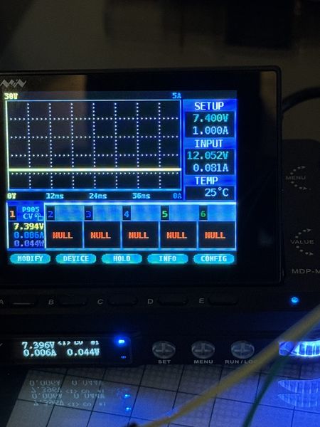
Now for testing! It was getting late, but I just had to see this board working. It was the first of its kind for me and I was pretty excited. I should have taken pictures, but I was on an adventure of discovery. I connected my MDP-P905 digital power supply to the input and connected my multimeter to the output. I set the input to the 7.4V setting for the battery I planned to use and set the current to 1A since that was the fuse I plan to use. When I applied power, the voltage input was good and the current settled at 35mA. However the output was fluctuating and various voltages up to 8V and thereabouts. I had a faulty circuit somewhere. I used my multimeter to trace from the input to the output and found the faulty trace that was the ground wire to the input capacitor. This is after I fixed it, but you can see the missing piece of the trace.
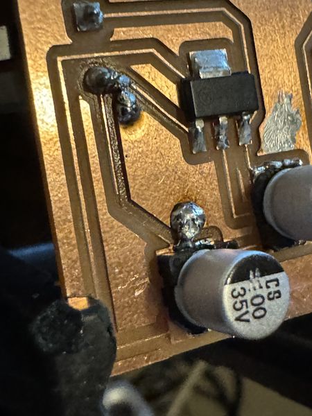
Long story short, I thought it vaporized, but it was done by me when I cleaned the board. After bridging the solder and testing, the power supply module worked and powered up my FABCAT board.
This is the setup to test the power supply module. You can see the output on the multimeter.
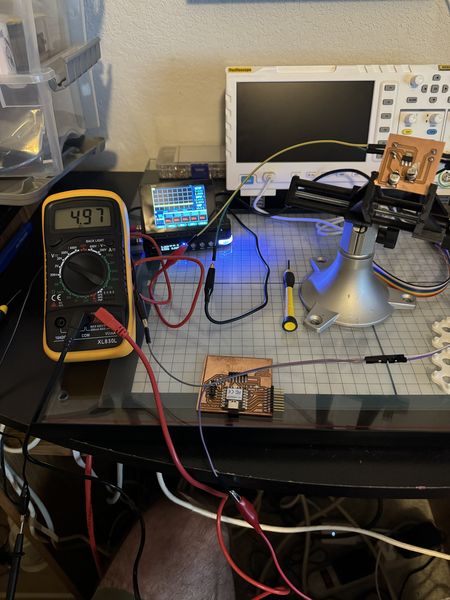
This shows the output of the digital power supply.
This is a video of powering up the FABCAT board with the digital power supply.
Now I have a power supply to prototype the Final Project :)
Embedded Microcontroller Interfacing and Programming
I combined the temperature sensor and NeoPixel Ring programs into a single program. I also used the code from the arduino program I used to test the NeoPixel Ring previously.
# Rui Santos & Sara Santos - Random Nerd Tutorials
# Complete project details at https://RandomNerdTutorials.com/raspberry-pi-pico-w-micropython-ebook/
# Modified by Jim Hart 4/1/2024
# Original Author https://electrocredible.com/neopixel-micropython-raspberry-pi-pico-ws2812b/
# Modified by Jim Hart on April 17, 2024

import machine, onewire, ds18x20, time, neopixel  # Added neopixel from electrocredible
from machine import Pin


# Pin configuration for DS18B20 temperature sensor
ds_pin = machine.Pin(29)
ws_pin = 6 # This is the pin I have the signal line attached to
led_num = 24 # This is the number of LEDs on my NeoPixel Ring
BRIGHTNESS = 0.2  # Adjust the brightness (0.0 - 1.0)

# Create DS18X20 object using OneWire protocol with specified pin
ds_sensor = ds18x20.DS18X20(onewire.OneWire(ds_pin))

# Create an instance of the NeoPixel class called neoRing
neoRing = neopixel.NeoPixel(Pin(ws_pin), led_num)

def celsius_to_fahrenheit(temp_celsius):
    # Convert temperature from Celsius to Fahrenheit
    temp_fahrenheit = temp_celsius * (9/5) + 32
    return temp_fahrenheit

def set_brightness(color):
    r, g, b = color
    r = int(r * BRIGHTNESS)
    g = int(g * BRIGHTNESS)
    b = int(b * BRIGHTNESS)
    return (r, g, b)

# Scan for DS18B20 sensors and print their ROM addresses
roms = ds_sensor.scan()
print('Found DS devices: ', roms)

while True:
    # Initiate temperature conversion for all sensors
    ds_sensor.convert_temp()
    time.sleep_ms(750)  # Wait for the conversion to complete (750 ms is recommended)

    for rom in roms:
        print(rom)

        # Read temperature in Celsius from the sensor
        tempC = ds_sensor.read_temp(rom)

        # Convert Celsius temperature to Fahrenheit
        tempF = celsius_to_fahrenheit(tempC)

        # Print the temperature readings
        print('temperature (ºC):', "{:.2f}".format(tempC))
        print('temperature (ºF):', "{:.2f}".format(tempF))
        print()

    time.sleep(5)  # Wait for 5 seconds before taking readings again
    # delay(1000);   # I put this in the loop because it was going too fast to observe
    if (tempF < 65): #{ # I selected this temperature since the ambient temperature is about 73 degrees
    # color(255,255,0); // turn the RGB LED blue
    # delay(1000); // delay for 1 second
    # Display blue
        color = (0, 0, 255)  # Blue color
        color = set_brightness(color)
        neoRing.fill(color)
        neoRing.write()
        time.sleep(1)
    #}
    elif (tempF > 75 and tempF < 85): #{ # I selected these temperatures since they are in the middle
    # color(255,0,255); // turn the RGB LED green
    # delay(1000); // delay for 1 second
    # Display green
        color = (0, 255, 0)  # Green color
        color = set_brightness(color)
        neoRing.fill(color)
        neoRing.write()
        time.sleep(1)
    #}
    elif (tempF > 85): #{ # I selected this temperature since it is below the temperature of my maximum 85 degrees
    # color(0,255,255); // turn the RGB LED red
    # delay(1000); // delay for 1 second
    # Display red
        color = (255, 0, 0)  # Red color
        color = set_brightness(color)
        neoRing.fill(color)
        neoRing.write()
        time.sleep(1)
    #}
I have not programmed in MicroPython much, so I had a few things to learn. The comments use a “#” rather than a “//”. The IF-THEN-ELSE is now ELIF and a “:” after the “(expression) rather than braces. MicroPython is also picky about indentation. After several iterations I had it working in the form above :)
The program must be saved as main.py to the RP2040 in order for it to run on powerup.
Linked from this page to any weeks that you worked on your final project
- Linked from this page to any weeks that you worked on your final project:
There is linkage between the Final Project and all but three of the assignments. The links for each week are in the updated table below
This is the updated table of Assignment Integration
| Assignment Integration | WBS Code |
|---|---|
| Week 1 (Principles and Practices, Project Management) | Final Project |
| Week 2 (Computer-Aided Design) | 1.2 |
| Week 3 (Computer-Controlled Cutting) | 1.2.11 |
| Week 4 (Electronics Production) Concept Plan | 1.3.1 |
| Week 5 (3D Scanning and Printing) Research | 1.2 |
| Week 6 (Embedded Programming) User Empathy | 1.3.1 |
| Week 7 (Computer-Controlled Machining) Define the Scope and Target Audience | Assignment |
| Week 8 (Electronics Design) Problem Solving | 1.3.1 |
| Week 9 (Output Devices) Define Project and Sketching | 1.3.3 |
| Week 10 (Mechanical Design, Machine Design) WBS, Assignment Integration, Risk Analysis and BoM | Assignment |
| Week 11 (Input Devices) Acquire Materials | 1.3.2 |
| Week 12 (Molding and Casting) Pre Production | 1.2.11 |
| Week 13 (Networking and Communications) Pre Production | 1.3.1 |
| Week 14 (Interface and Application Programming) Project Production | Assignment |
| Week 15 (Wildcard Week) Test and Control | 1.2.10 |
| Week 16 (Applications and Implications) Plan Communications | Final Project |
| Week 17 (System Integration) Preproduce Audiovisuals and Video Editing | 1.3 |
| Week 18 (Invention, Intellectual Property and Income) Poster Production/Slide | Final Project |
System Integration
The next step is to install the hardware in Electronics Housing. The simplest way I could think of and still look acceptable was to use hook and loop material with adhesive on one side. Here’s the sketch and where the material will go.
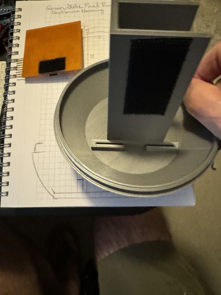
Hook applied.
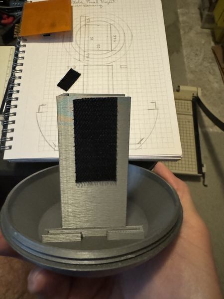
Loop applied.
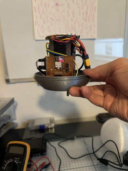
FABCAT Board attached.
Power supply loop.
Power supply attached.
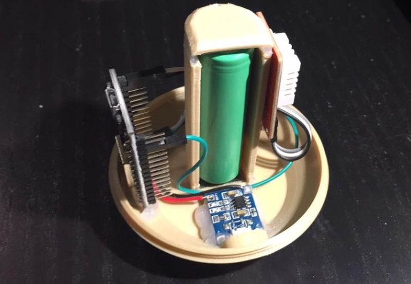
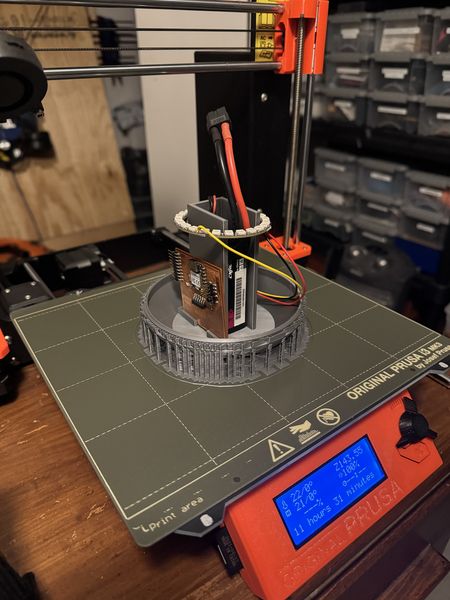
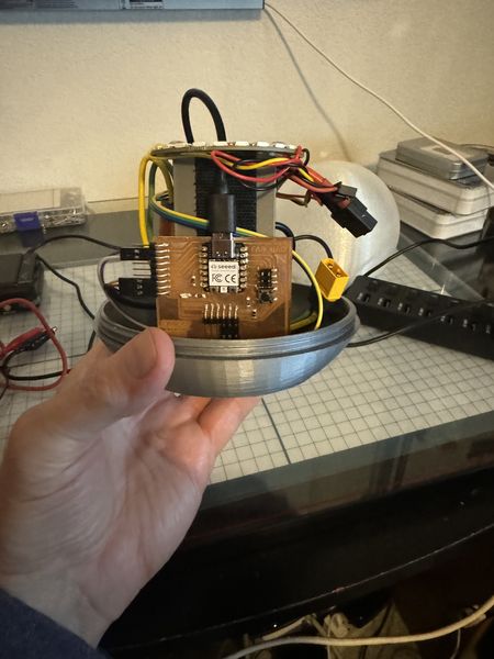
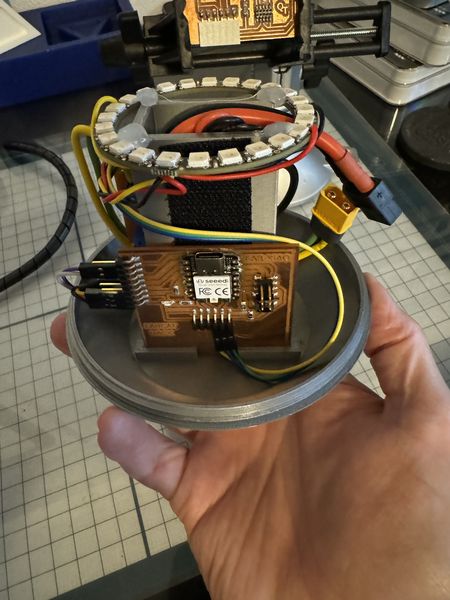
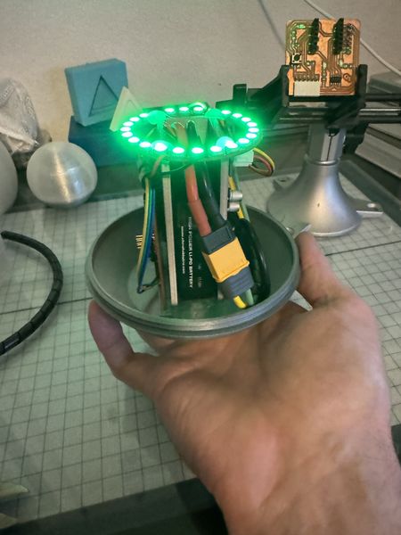
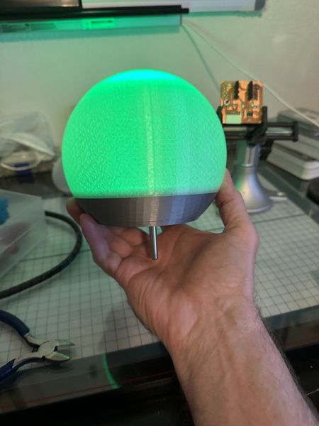
Here’s a few shots after assembly.
![]()
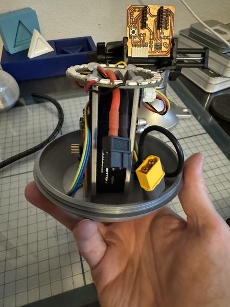
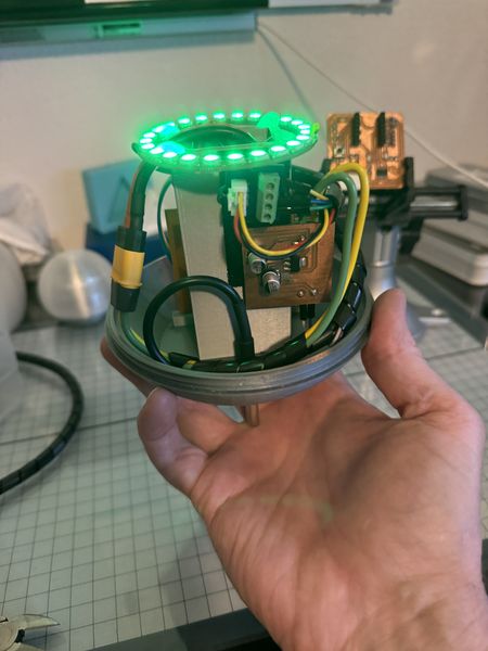
Now that the hardware is installed, I need to apply battery power and test the FABCAT board operating on the onboard battery. This is an image of the Electronics Housing operating on battery power.
The next step is to program the FABCAT using the USB-C connection. To do this I must disconnect the battery. While I do this, I will add some hook and loop inside the Battery Holder to hold the battery in place during operation.
This will hold the battery in place.
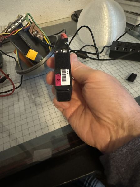
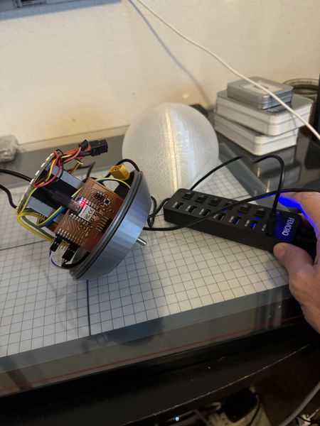
With the battery secured and disconnected, I will plug in the USB-C connector to the FABCAT board to connect to the computer.
Then I turn on the USB hub to connect to the computer.
Documented how you implemented system integration in your final project
- Documented how you implemented system integration in your final project:
During this week, I got a little jump on the upcoming System Integration Week by organizing the wires in the Smart Buoy by using wire management.
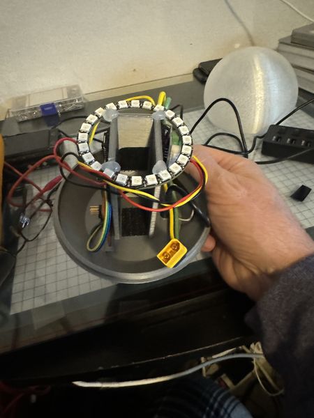
Here are some images before wire management.
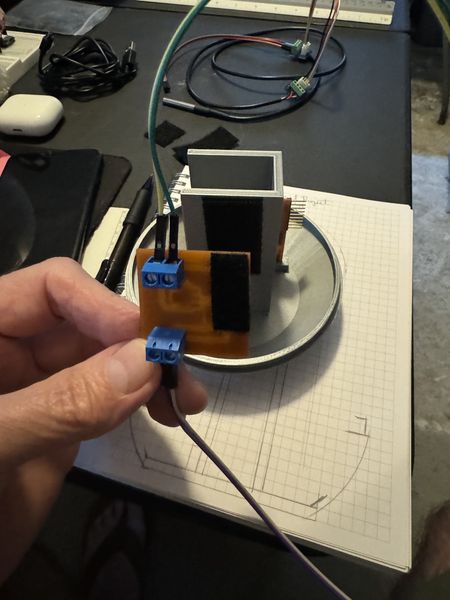
This is the Power Supply Module and the Grove - Screw Terminal Module for the NeoPixwl LED Ring.
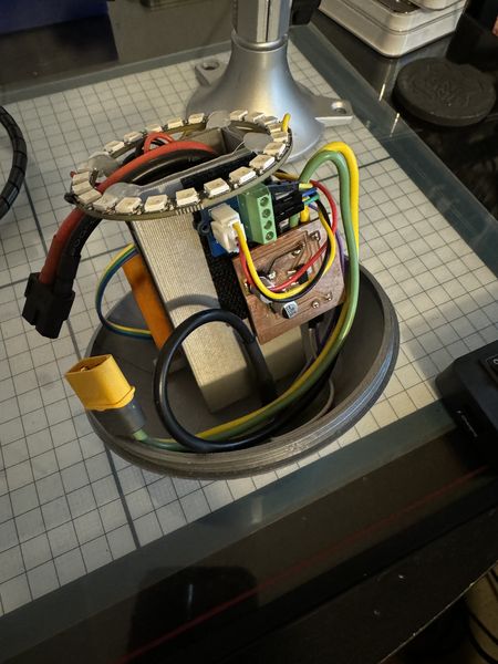
This is an empty side showing the back of the Power Supply Module and a “tangle of wires”.
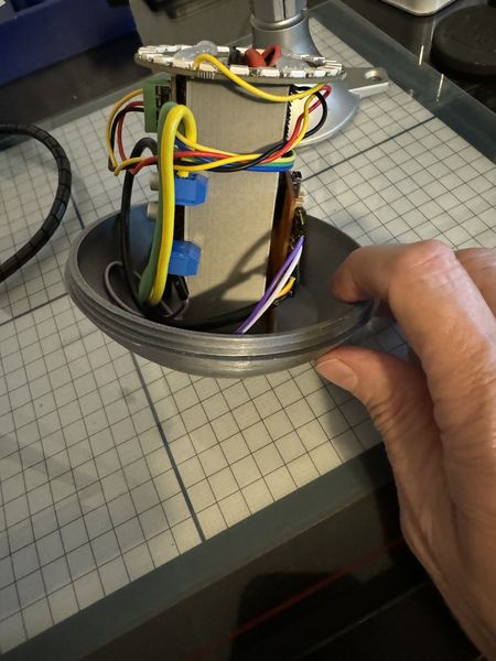
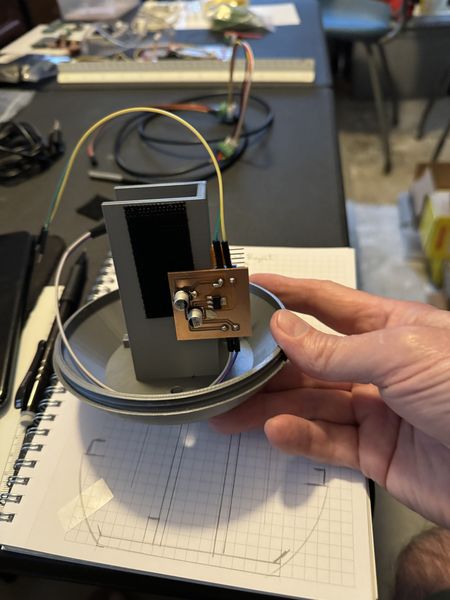
This is the side with the FABCAT Board and more wires.
This is the side for Battery Holder access.
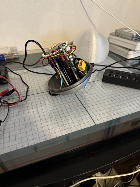
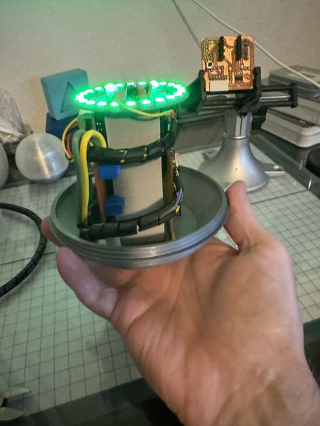
I used the wire management coils that came with my MakerMade CNC500. I had extra so they came in handy. These are images after installing wire management and verifying proper operation.

Linked to your presentation.png and presentation.mp4; make sure they are located to the root of your website
- Linked to your presentation.png and presentation.mp4; make sure they are located to the root of your website:
I am scheduled to present my Final Project to Professor Neil on Wednesday at the end of the session. You are welcome to join with us or view the video if you can’t be there. The links to my Personal Website, Presentation Slide, and the Presentation Video are on the schedule for Wednesday, 05 Jun 2024. The actual time may vary based on attendance.
Included the license you chose
- Included the license you chose:
The ThermoSphere Final Project may interest hobbyists and anglers to assist them with fishing. This project was funded as a personal expense for learning and fun. As my website shows in the footer, I am using the Creative Commons Attribution-NonCommercial-ShareAlike 4.0 International License.
Included all of your original design files in the archive (2D & 3D, board files & code). No external hosting of final project files - discuss file sizes with your instructor
- Included all of your original design files in the archive (2D & 3D, board files & code). No external hosting of final project files - discuss file sizes with your instructor:
Computer-Aided Design
-
Lettering of FABCAT Fab Lab V2 fabcat_lettering_v2.psd 305 Kb
-
Exchange File for 2D fabcat_lettering.svg 14 Kb
-
3D Design Files 3d_design.zip 122 Kb
-
Exchange File for Composite Shape composite_unwrap.stl 41 Kb
-
Exchange File for Electronics Housing electronics_housing.stl 209 Kb
-
Exchange File for Sensor Globe sensor_globe.stl 669 Kb
-
Exchange File for Inner Form inner_form.stl 164 Kb
-
Exchange File for Outer Form outer_form.stl 191 Kb
-
Exchange File for ThermoSphere Stand thermosphere_stand.stl 56 Kb
Computer-Controlled Cutting
- Cut Files computer_cutting.zip 11 Kb
Electronics Design and Production
- Board Files electronics.zip 291 Kb
3D Printing
-
Electronics Housing electronics_housing.zip 4.8 Mb
-
Inner Form inner_form.zip 2.6 Mb
-
Outer Form outer_form.zip 1.5 Mb
-
Support Ring support_ring.zip 1 Mb
-
Sensor Globe sensor_globe.zip 9.3 Mb
Embedded Programming
- MicroPython Code programming.zip 2 Kb