Embedded Programming
This week I learned about embedded programming. This included:
Unit Description
Group assignment:
- Browse through the datasheet for your microcontroller
- Compare the performance and development workflows for other architectures
- Document your work to the group work page and reflect on your individual page what you learned
Individual assignments:
- Write a program for a microcontroller development board to interact (with local input &/or output devices) and communicate (with remote wired or wireless devices)
Learning outcomes
- Implement programming protocols.
Checklist
Linked to the group assignment page:
-
Linked to the group assignment page:
-
Although there are two types of assignments, one group and one individual, since I am alone in my personal Fab Lab I will do both. All of my work will be documented here, so there won’t be a group assignment page. (My instructor encouraged me to do this and Adrian said it best :)
-
Compare the performance and development workflows for other architectures and document your work as you go by reflecting what you learned.
My first dive into microcontrollers was through the link in the unit page through machines that make MTM Great information and I appreciate the effort put into this page. It answered many questions that I had.
I was also interested in the types of architectures that exist among the microcontrollers, so I Googled that. As Neil mentioned in class, there are two: Von Neumann and Harvard, that are Complex Instruction Set Computer (CISC) and Reduced Instruction Set Computer (RISC) respectively. The cool discovery was the history it played in the US Navy; I found this information here in an archive. “Many years ago, the United States government asked Harvard and Princeton Universities to come up with a computer architecture to be used in computing tables of Naval artillery shell distances for varying elevations and environmental conditions. Princeton’s response was a computer that had common memory for storing the control program as well as variables and other data structures. It was best known by the chief scientist’s name ‘Von Neumann’”
The author went on to say, “It might at first seem that the memory interface unit is a bottleneck between the processor and the variable/RAM space (especially with the requirement for fetching instructions at the same time); however, in many Princeton architected processors, this is not the case because the time required to execute a given instruction can be used to fetch the next instruction (this is known as pre-fetching) and is a feature on many Princeton architected processors…The Princeton architecture won the competition because it was better suited for the technology of the time. Using one memory was preferable because of the unreliability of current electronics (this was before transistors were in widespread use). A single memory interface would have fewer things that could go wrong.” It is nice to learn more of the Naval heritage associate with computer technology.
I found another valuable website that compares the two architectures after describing both. GeeksForGeeks Von Neumann as well as GeeksForGeeks Harvard. And here is a good discription of the difference
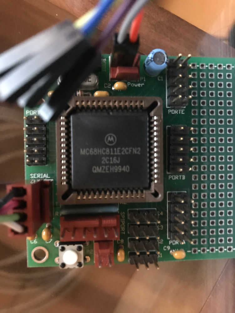
This was a trip down memory lane…literally. I decided to get back into the microcontroller I purchased after I moved to Missouri. It was just after Y2K when the digital storm had settled. The invoice is dated 04/11/2000! I purchased the BotBoard Plus and RS232/TTL Serial Cable Kit; plus a container of Kester Paste Flux for the required soldering I would be doing. All for $51.00 :) I assembled the board and tested it satisfactorily and then got busy building my Wireless ISP business that was incorporated 04/16/2001.
Documented what you learned from browsing through a microcontroller datasheet:
- Documented what you learned from browsing through a microcontroller datasheet:
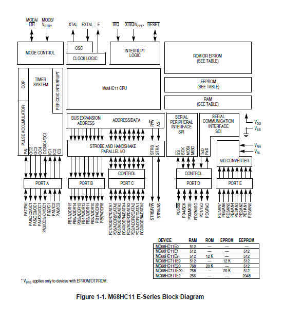
This is the block diagram of the structure of the Motorola MC68HC11 chip; my version is the 68HC811E2CFN2. It is listed as the last device of the table in the image:
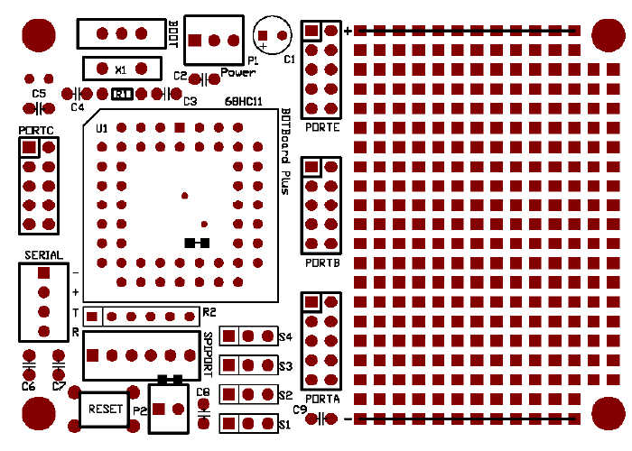
This is the BotBoard Plus layout:
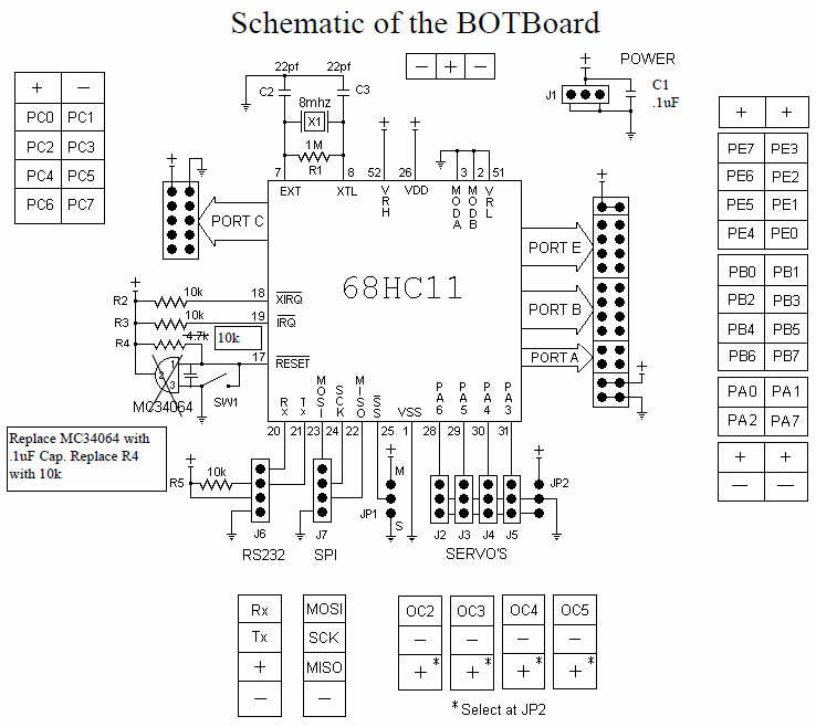
And the schematic:
Documented what you learned from browsing through a microcontroller datasheet:
- Documented what you learned from browsing through a microcontroller datasheet:
Features of the E-series devices include:
- M68HC11 CPU
- Power-saving stop and wait modes
- Low-voltage devices available (3.0–5.5 Vdc)
- 0, 256, 512, or 768 bytes of on-chip RAM, data retained during standby
- 0, 12, or 20 Kbytes of on-chip ROM or EPROM
- 0, 512, or 2048 bytes of on-chip EEPROM with block protect for security
- 2048 bytes of EEPROM with selectable base address in the MC68HC811E2
- Asynchronous non-return-to-zero (NRZ) serial communications interface (SCI)
- Additional baud rates available on MC68HC(7)11E20
- Synchronous serial peripheral interface (SPI)
- 8-channel, 8-bit analog-to-digital (A/D) converter
- 8-bit pulse accumulator
- Real-time interrupt circuit
- Computer operating properly (COP) watchdog system
16-bit timer system:
- Three input capture (IC) channels
- Four output compare (OC) channels
- One additional channel, selectable as fourth IC or fifth OC
38 general-purpose input/output (I/O) pins:
- 16 bidirectional I/O pins
- 11 input-only pins
- 11 output-only pins
Several packaging options:
- 52-pin plastic-leaded chip carrier (PLCC)
- 52-pin windowed ceramic leaded chip carrier (CLCC)
- 52-pin plastic thin quad flat pack, 10 mm x 10 mm (TQFP)
- 64-pin quad flat pack (QFP)
- 48-pin plastic dual in-line package (DIP), MC68HC811E2 only
- 56-pin plastic shrink dual in-line package, .070-inch lead spacing (SDIP)
It was good to get back into my long lost hobby this cycle! Things have changed a bit :) I still have the 3.5” floppy that came with the BotBoard Plus, so I dug into the software and manuals. The CLI software was still functional, but it would not program the microcontroller in Windows 10 for some reason. I searched the Internet and found a better GUI replacement on Sourceforge called JBug11. It had everything I needed and then some…
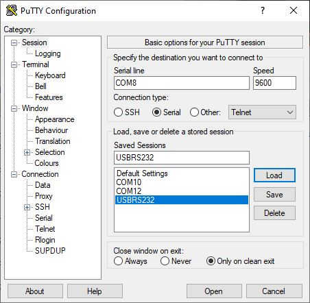
This is my setup to power up and communicate with the BotBoard Plus:
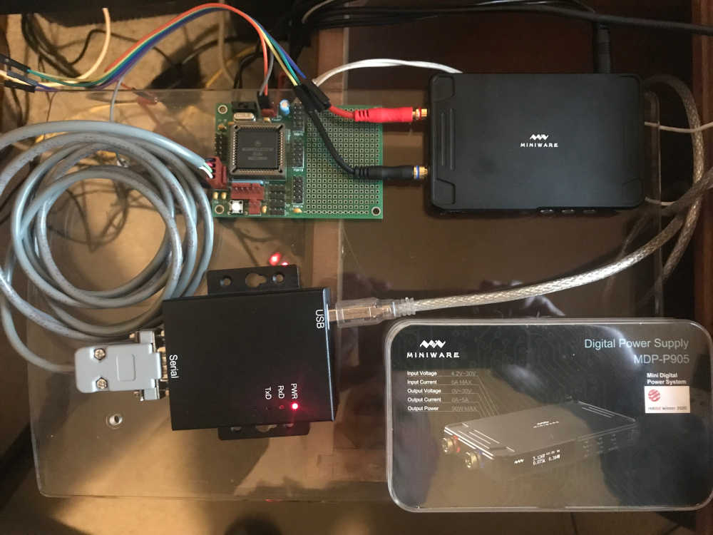
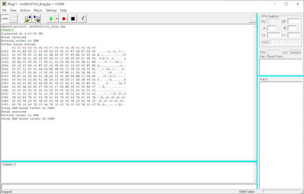
The BOOT switch is in Program position (slid toward the power connector) and communication established with JBug11 through the USB to RS232 adapter: Using RAM based talker on COM8:
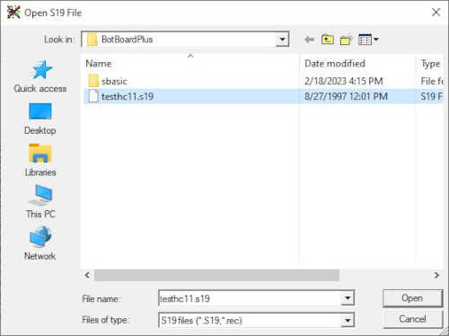
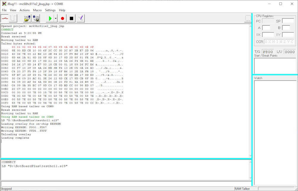
Uploading test software to the microcontroller:
Uploading complete!
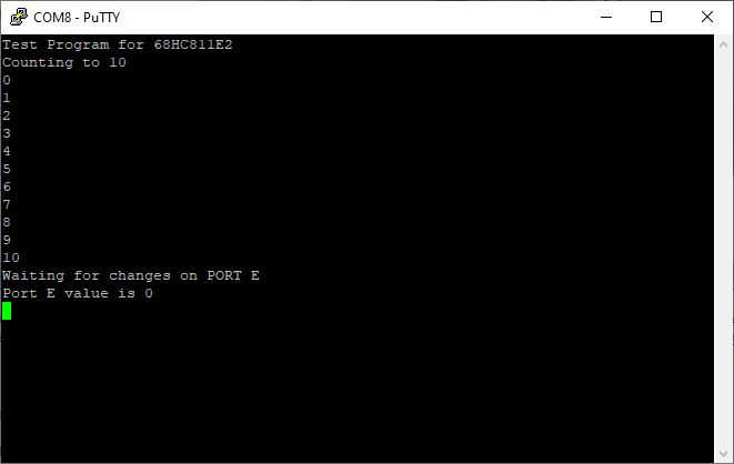
Switched BotBoard to BOOT and communicated using PuTTY
Success!!
I hope you enjoyed the microcontroller intro. I just wanted you to know I have been thinking about these things for a long time :)
Further thinking has been invested it the Mindstorms Robotics Invention Systems 1.5 (RCX)

and the EV3 (LEGO catalog #31313).

My children and I enjoyed learning on these kits and I look forward to learning more with these microcontrollers. (My children have grown up and moved away :)
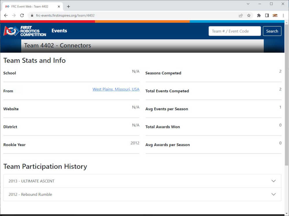
In 2012 I became involved with FIRST Robotics Competition; our West Plains High School students, Team 4402 - Connectors, participated in St. Louis during the 20th and 21st FRC Season and performed well. I will cover that in a future documentation spiral.
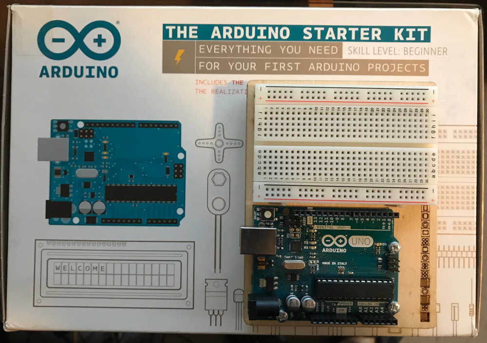
My interest sparked again on March 30, 2015 when I purchased an Arduino Starter Kit.
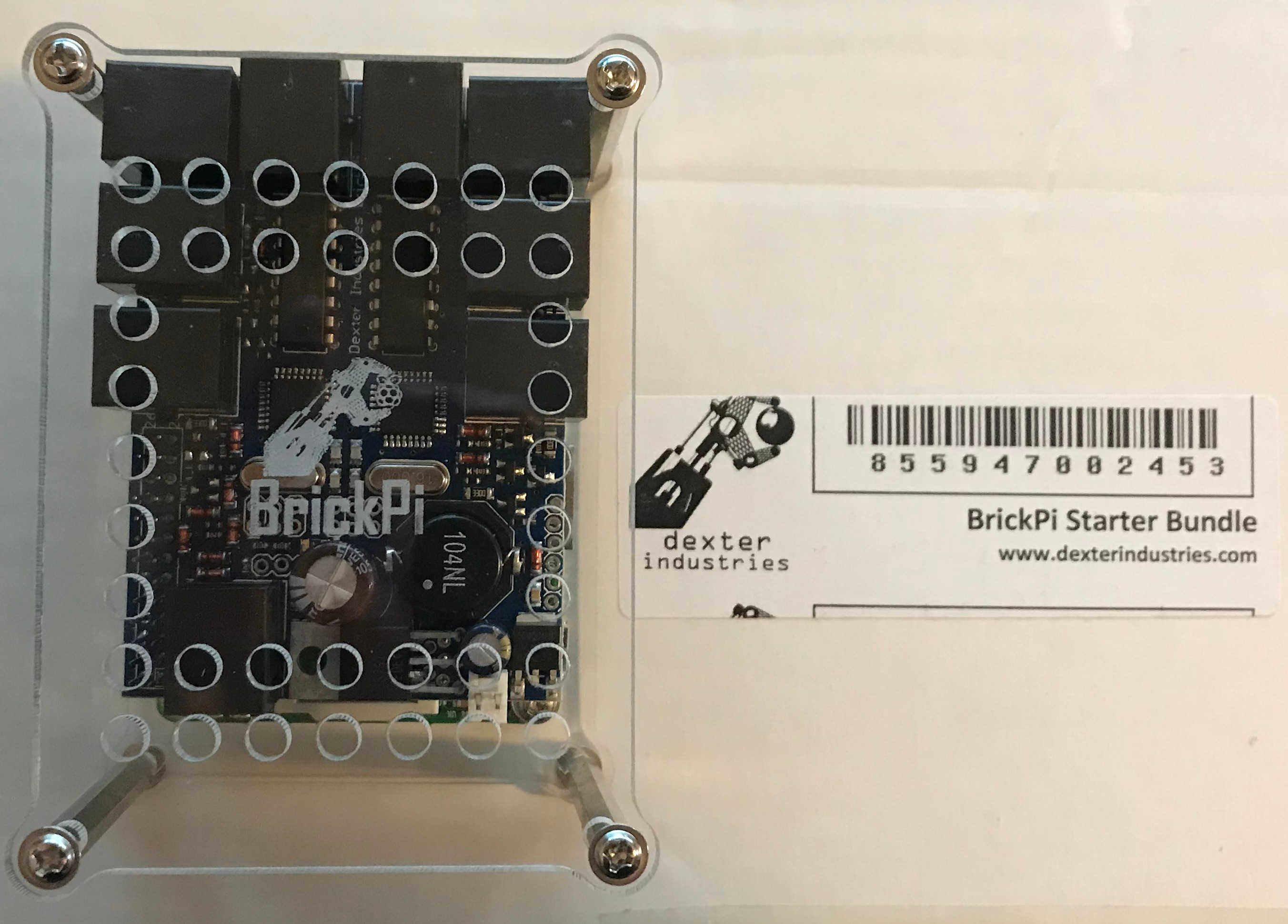
A month later, April 28, 2015, I purchased the BrickPi Starter Bundle (Raspberry Pi B+).
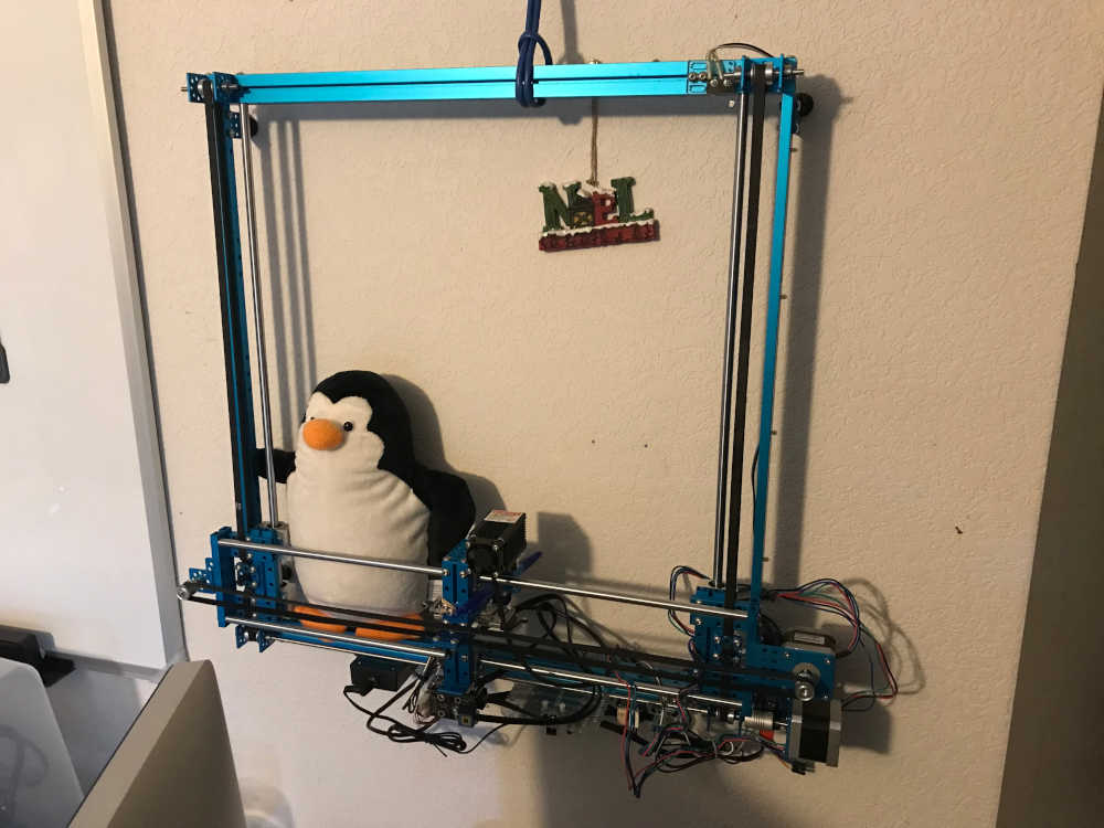
On October 26, 2015, I purchased the Makeblock XY-Plotter Robot Kit v2.0

as well as a Laser Engraver Upgrade.
All of these microcontrollers were leading up to my discovery of the Fab Academy and the concept of a Fab Lab; this occured in 2016. I designed and built my first Fab Lab following the Ideal Lab Layout in 2017; it flooded and then I rebuilt it in time for enrollment in Fab Academy 2019. Yet another story to tell/document :)
-
Used Atmel Studio 7.0 to read a USBTiny device using the Atmel ICE as the tool, but could not access it. I tried reading an Arduino UNO which did work. Prefer to use avrdude going forward
-
Skimmed the data sheet for the ATtiny and found the section on temperature measurement. I will be able to use this for my wearable temperature display. Also found the table of contents at the end.
-
Waves were coming in big sets and I got washed into shore a couple of times. I paddled out, again, each time; and now I can ride these waves and will only improve with practice.
-
The main obstruction was the coding and wondering whether I was doing it right. Although I got the FabTinyISP made and programmed twice, I still felt like I cookbooked the whole process and didn’t truly understand what I was doing. I followed http://fab.cba.mit.edu/classes/863.16/doc/projects/ftsmin/index.html and really appreciated the help. I am not comfortable yet, but I will be with time.
-
When I visited LCCC, I had been dabbling in Eagle, but I really wanted to learn to use the python code that Neil showed us. Paul and Bridgette helped, but I just didn’t like the interface. Eagle was nice for stuffing the board, but the trace placement was a little frustrating. I couldn’t put the traces exactly where I wanted to and was at the mercy of the “program”. This was in the “Make Something Big” week and I was already behind. I really needed to get things going to get caught up.
-
When I got back home, I really immersed myself into the python and got “outside”. I used the board image and the hello.ftdi.44.py to get the hang of it. Once I got the switch and LED figured out, I needed to learn how to program the board. I wasn’t even sure if my FabTinyISP would be able to program my Hello World board. Thankfully, I did manage to program and Putty into the Hello World board and make it talk to me 🙂 I made that entry in Week 7 Electronics Design where it was supposed to be done.
-
Next I had to build the Input Board. I intended to use temperature as my input. I spent a lot of time trying to refine my documentation process; I’m still not there, yet. After organized git and mkdocs, I immersed myself into python. I used Neil’s board as a guide and stuffed the python board from scratch; that, running the traces, and milling the board took the rest of my Saturday. That night, I made Hello World work. On Sunday, I got the LED to flash S-O-S when I held the button.
-
Here are some artifacts of where I have been. Kelly Shaw really helped me out today! Thanks, Kelly!! http://fab.cba.mit.edu/classes/863.11/people/kelly.shaw/week7_embedded_programming.html
-
Referred me to this http://highlowtech.org/?p=1695 and this http://highlowtech.org/wiki/pmwiki.php?n=Main.AVRProgrammingAdvanced But this was the biggest find of all from Kelly http://www.nongnu.org/avr-libc/ and this http://www.nongnu.org/avr-libc/user-manual/pages.html and got me to this https://www.microchip.com/webdoc/AVRLibcReferenceManual/group__avr__io.html
-
I tried to program the ATMega328P, but I will have to save that for another day https://www.sparkfun.com/datasheets/Components/SMD/ATMega328.pdf
Code Example
// LED Button S-O-S Program
//Credit goes to Kelly Shaw MAS.863 / FALL 2011 for the assistance I discovered through Google
#include <avr/io.h>
#define F_CPU 1e6
#include <avr/delay.h>

#define TRUE 1
#define FALSE 0

int main()
{
//SETUP
//Button is on PB2
//LED is PA7

PORTB= _BV(PB2); //Turn button pullup resistor on
DDRA = _BV(PA7); //Enable output on the LED pin
PORTA = _BV(PA7); //Turns LED on

//LOOP
while (TRUE)
{
if ((PINB & _BV(PB2))) //button is not pushed
{
PORTA = 0; //turn LED off
}
else
{
PORTA = _BV(PA7); //turn LED on
_delay_ms(500);
PORTA = 0;
_delay_ms(500);
PORTA = _BV(PA7); //turn LED on
_delay_ms(500);
PORTA = 0;
_delay_ms(500);
PORTA = _BV(PA7); //turn LED on
_delay_ms(500);
PORTA = 0;
_delay_ms(1500);
PORTA = _BV(PA7); //turn LED on
_delay_ms(1500);
PORTA = 0;
_delay_ms(1500);
PORTA = _BV(PA7); //turn LED on
_delay_ms(1500);
PORTA = 0;
_delay_ms(1500);
PORTA = _BV(PA7); //turn LED on
_delay_ms(1500);
PORTA = 0;
_delay_ms(500);
}
}
}
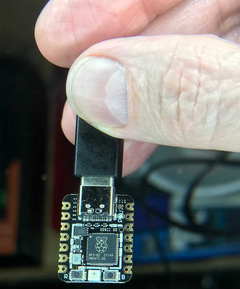
There are many chips in my possession to talk about, but I must finish this assignment. There has been a great deal of excitement about the Seeed Studio XIAO development board, and rightly so! After looking at the past, I must say, things are getting smaller, faster, better, cheaper. It’s a great time to be alive!
So, here we go!
In keeping with the order of discovery of the MC68HC11 above, my first image will be the microcontroller. They told me not to take the cover off…but that was just a tease. Look at this!
Documented what you learned from browsing through a microcontroller datasheet:
- Documented what you learned from browsing through a microcontroller datasheet:
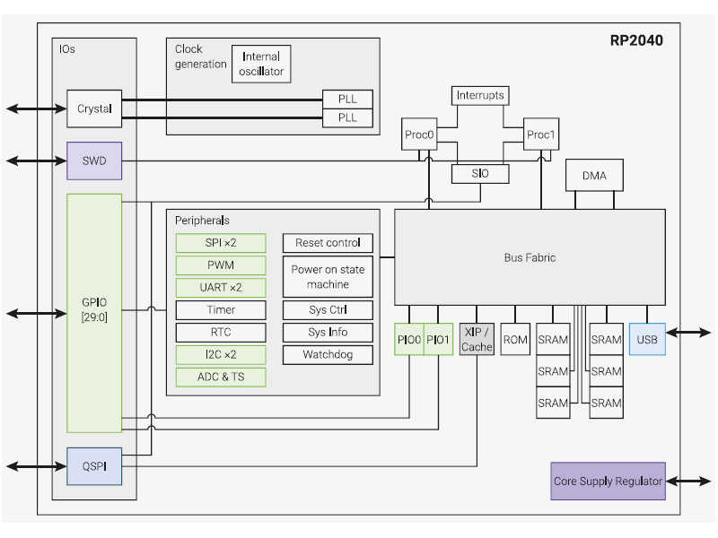
After studying the RP2040 Datasheet, this is the block diagram of the structure of the RP2040 chip; my chip is contained in the Seeed Studio XIAO RP2040 board:
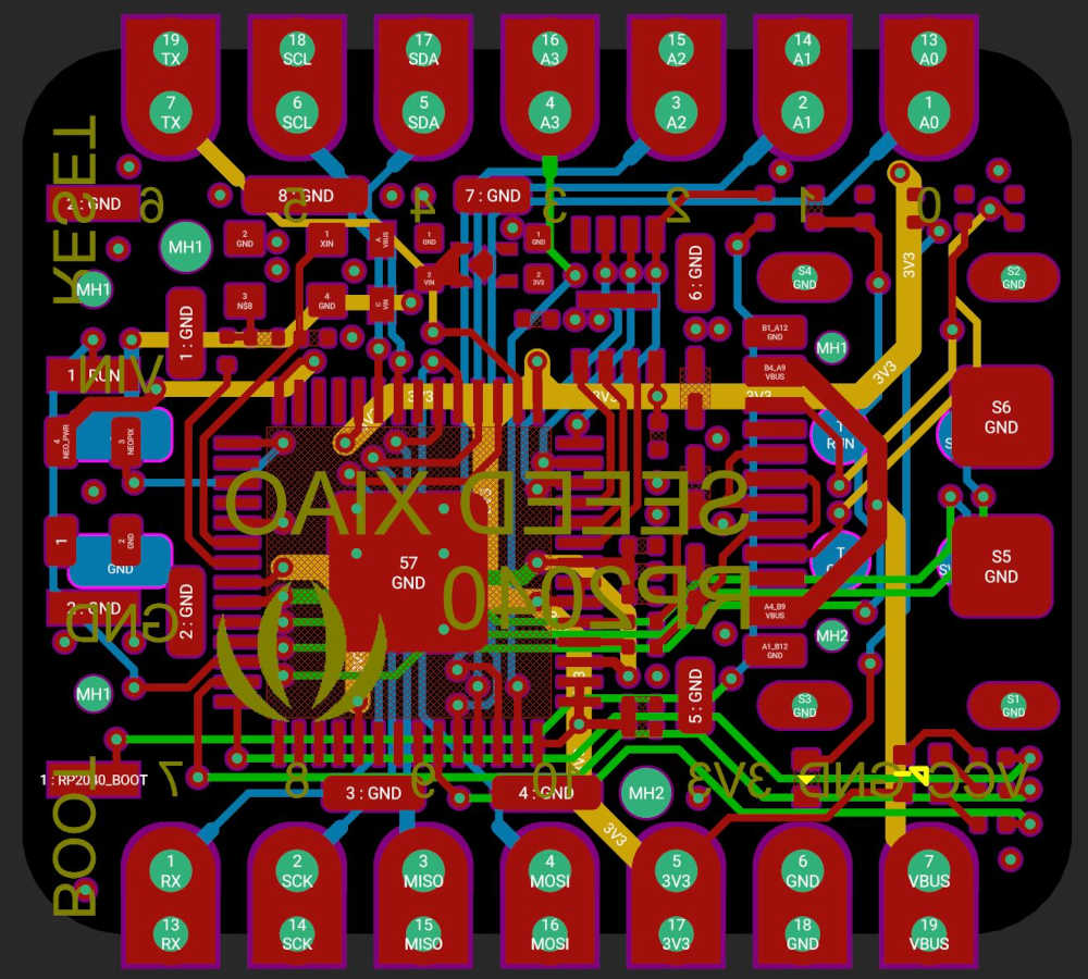
This is the Seeed XIAO RP2040 board layout:
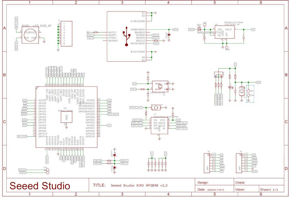
And the schematic:
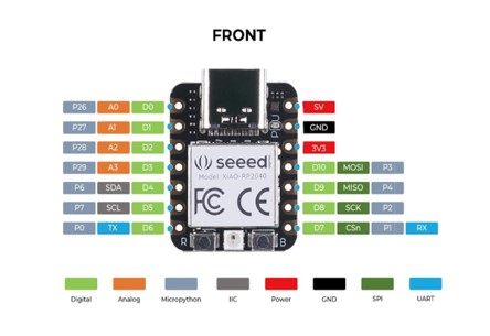
And the board pinout:
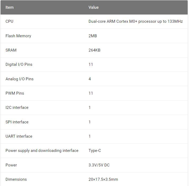
Features of the Seeed Studio XIAO RP2040 include:
- Powerful MCU: Dual-core ARM Cortex M0+ processor, flexible clock running up to 133 MHz
- Rich on-chip resources: 264KB of SRAM, and 2MB of on-board Flash memory
- Flexible compatibility: Support Micropython/Arduino/CircuitPython
- Easy project operation: Breadboard-friendly & SMD design, no components on the back
- Small size: As small as a thumb(20x17.5mm) for wearable devices and small projects.
- Multiple interfaces: 11 digital pins, 4 analog pins, 11 PWM Pins,1 I2C interface, 1 UART interface, 1 SPI interface, 1 SWD Bonding pad interface.
Specification:
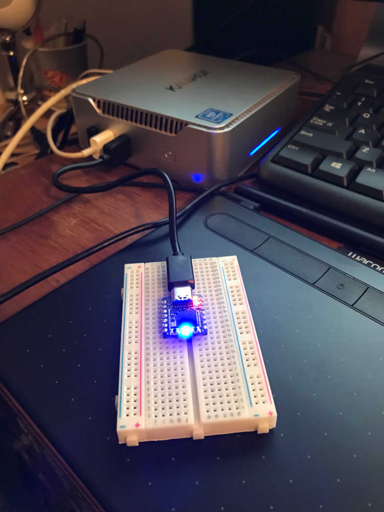
This is my setup to power up and communicate with the Seeed Studio XIAO RP2040:
Before I go into programming this microcontroller, I want to share a little treat I found in my research. Seeed Studio went out of their way to teach the world about this technology and I really appreciate it! So here’s to our friends at Seeed Studio…Thank You!!
Programmed your board to interact and communicate:
- Programmed your board to interact and communicate:
Described the programming process(es) you used:
- Described the programming process(es) you used:
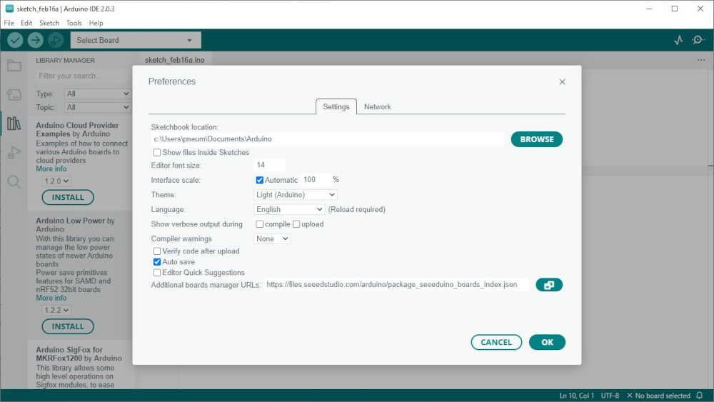
Now that I have this wonderful board in my possession, setting up the development environment is the next order of business. I will be using the Arduino IDE for this exercise. I have installed version 2.0.3 a,d I must set it up for the Seeeduino Boards; this requires adding it to the Board Manager. Click on File > Preference, and fill Additional Boards Manager URLs with the url below: https://files.seeedstudio.com/arduino/package_seeeduino_boards_index.json Click OK
Click Tools > Board > Boards Manager…, type keyword “Seeeduino XIAO” in the searching blank. The “Seeed SAMD Boards” will be listed. Click Install.
Connect the XIAO to the computer with a USB Type C data cable. I previously soldered the header pins on the board for ease of mounting on a prototyping board.
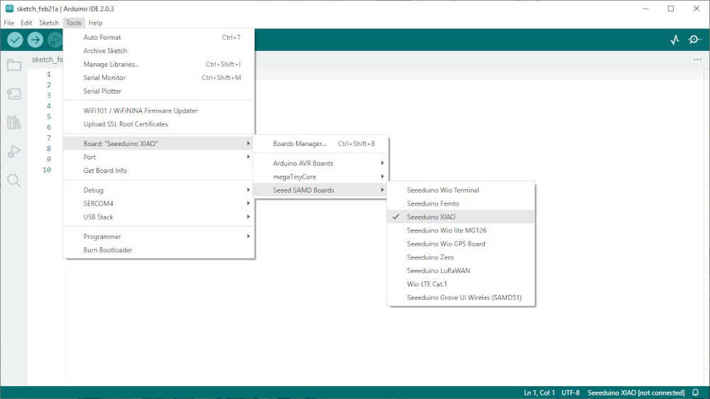
After connecting the board, click Tools > Board, find “Seeeduino XIAO ” and select it.
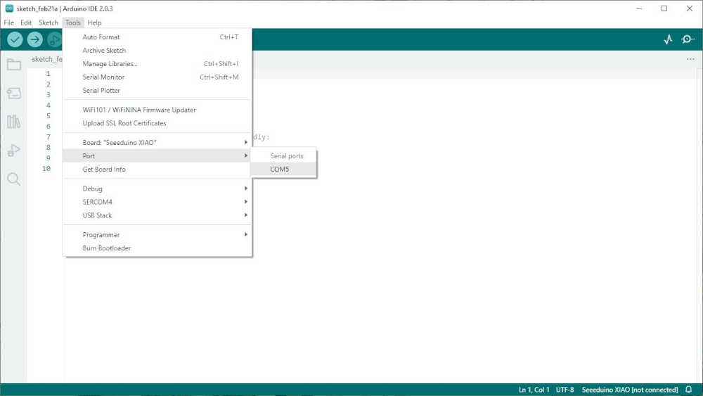
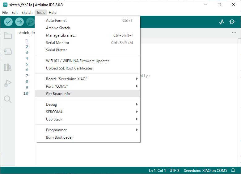
Select the serial device of the Arduino board from the Tools > Port > Serial ports. This is likely to be COM3 or higher. Mine was COM5. Click the appropriate COM port.
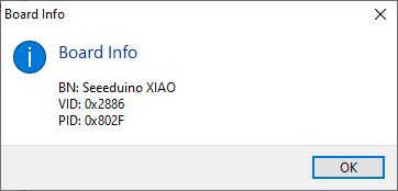
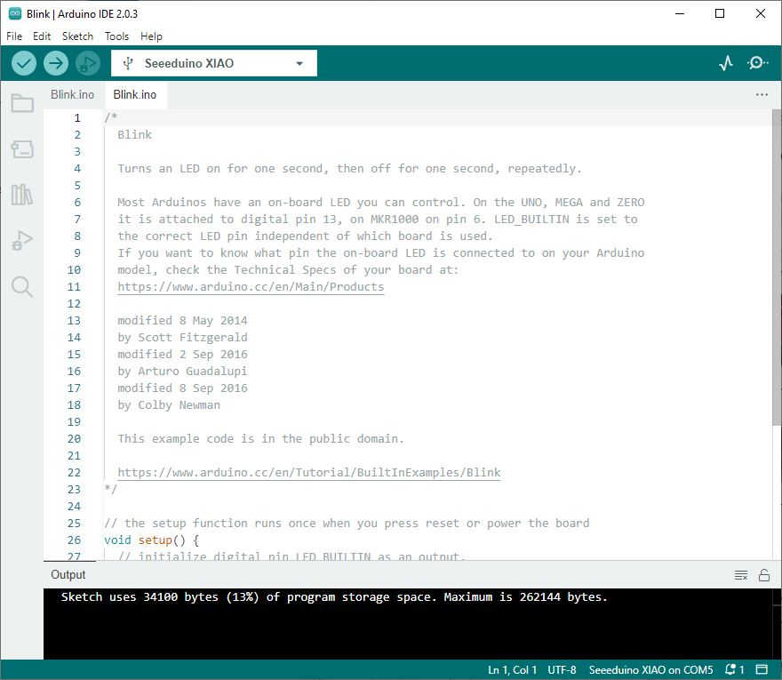
Now that my board is connected, I can get the board information as the Arduino IDE sees it:
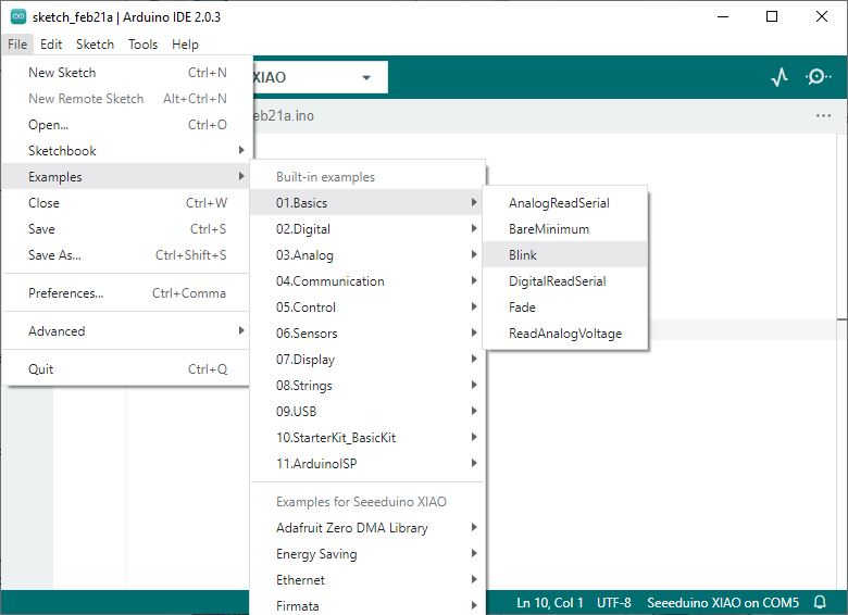
This cycle, I discovered from our friends at Seeed Studio that, “Just as hello world is the first lesson of all programming languages, blink is equivalent to Hello world in Arduino programming, which is a key to our Arduino learning journey.” So that is what we will do. File > Example > 01.Basics > blink
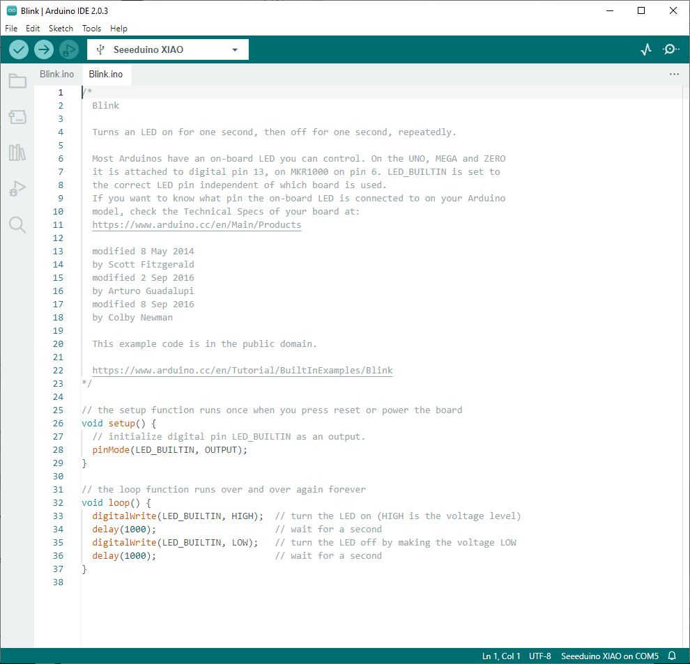
Look over the program and make sure the connection is still established:
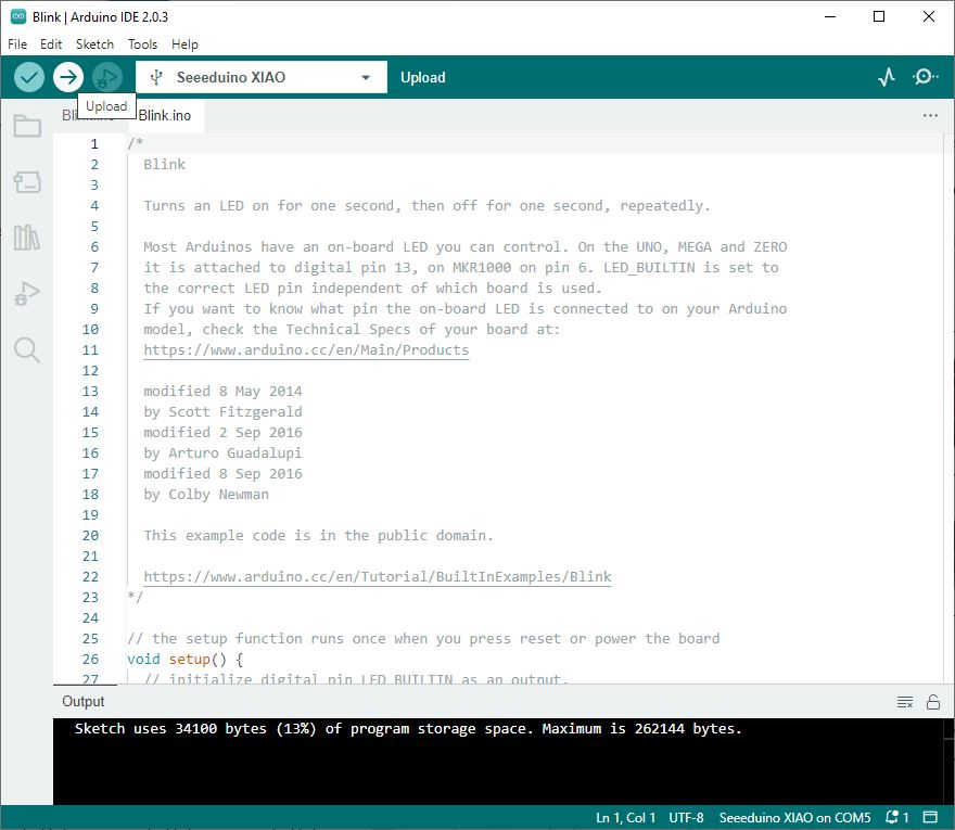
Next, upload the program. Before uploading, click the “Verify” button to verify whether the program is correct or not. If “Done compiling” is displayed, the program is correct.
Click the “Upload” button, and the debugging window will display “Project being compiled > Upload”.
Unfortunately, the program did not upload and gave me an error in the output.
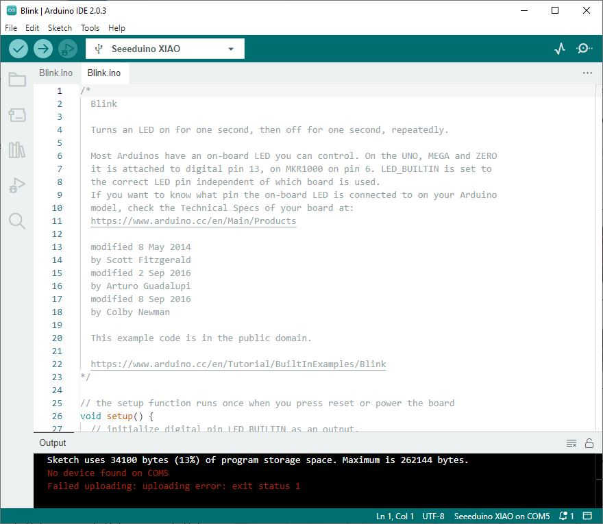
I pressed the Reset button and the board connected again and the lights started flashing again. However, I was still unable to upload the program. I consulted with Seeed Studio through the Internet and the response was, If the upload code appears to have failed to upload, try the following steps. Press and hold the “R” button on the XIAO RP2040, then press the “B” button again, the XIAO will enter the BootLoader, please upload the code again, it may fail again. Then the upload will be successful.”
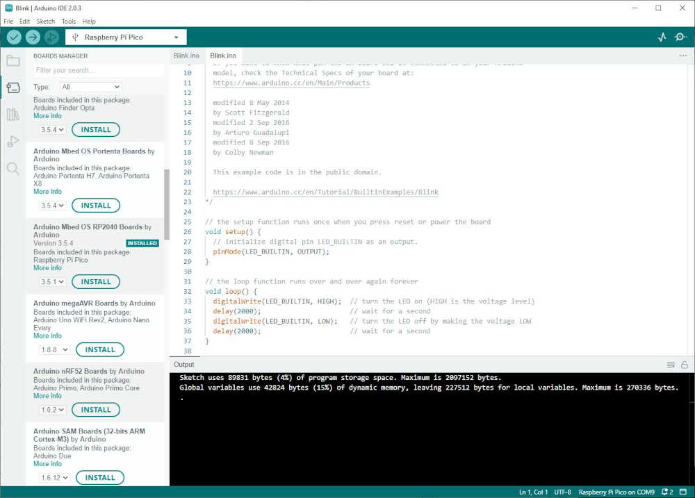
This did not work for me, so I went back to the forum, but this time in Arduino. I found this, “My error stream was “An error occurred while uploading the sketch.” I went to do what seeedneeerd suggested but noticed that the arduino boards manager has a Raspberry Pi Pico/RP2040 section. In this section the Seeed Xiao RP2040 is included. After downloading the Raspberry Pi Pico/RP2040 boards, the blink sketch was able to upload successfully.” So I’ll give this a try. It worked!!! Yay :)
So, now that data is flowing, I will modify the blink time to make sure I have control of this board. Let’s make it blink faster :)
Success!!
Okay! Now I will blink an external LED off of the XIAO RP2040. Not a major leap, but I am runnig out of time :)
Included your source code:
- Included your source code:
const int ledPin =  1;

// the setup function runs once when you press reset or power the board
void setup() {
  // initialize digital pin LED_BUILTIN as an output.
  pinMode(LED_BUILTIN, OUTPUT);
  pinMode(1, OUTPUT);
}

// the loop function runs over and over again forever
void loop() {
  digitalWrite(LED_BUILTIN, HIGH);  // turn the built-in LED on (HIGH is the voltage level)
  digitalWrite(ledPin, HIGH);       // turn the external LED on (HIGH is the voltage level)
  delay(500);                      // wait for half a second
  digitalWrite(LED_BUILTIN, LOW);   // turn the built-in LED off by making the voltage LOW
  digitalWrite(ledPin, LOW);        // turn the external LED off by making the voltage LOW
  delay(500);                      // wait for half a second
}
This is a continuation of the Embedded Programming week in Fab Academy 2024
-
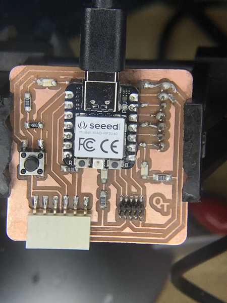
I will be using the QuenTorres swd+uart adapter+hello board - XIAO RP2040 that I made in Electronics Production week to complete this assignment.
-
I had some rework I needed to do before completing this assignment. My breakout pins were damaged due to applying too much pressure to mount the board on a breadboard. The little solder points can’t take much abuse and I overdid it. I repaired it, but it’s not as pretty as it was.
-
I will follow the steps I took to program the XIAO RP2040 last cycle and see what happens :)
-
The first thing I did was update to Arduino IDE 2.3.2, so that may help with a few errors I had before.
-
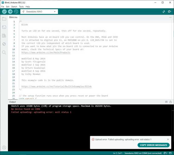
Next, I plugged in my QuenTorres board and found it on COM4. The software for the board was already installed and it detected it.
-
I uploaded the following code:
/*
  Blink

  Turns an LED on for one second, then off for one second, repeatedly.

  Most Arduinos have an on-board LED you can control. On the UNO, MEGA and ZERO
  it is attached to digital pin 13, on MKR1000 on pin 6. LED_BUILTIN is set to
  the correct LED pin independent of which board is used.
  If you want to know what pin the on-board LED is connected to on your Arduino
  model, check the Technical Specs of your board at:
  https://www.arduino.cc/en/Main/Products

  modified 8 May 2014
  by Scott Fitzgerald
  modified 2 Sep 2016
  by Arturo Guadalupi
  modified 8 Sep 2016
  by Colby Newman

  This example code is in the public domain.

  https://www.arduino.cc/en/Tutorial/BuiltInExamples/Blink
*/

// the setup function runs once when you press reset or power the board
void setup() {
  // initialize digital pin LED_BUILTIN as an output.
  pinMode(LED_BUILTIN, OUTPUT);
}

// the loop function runs over and over again forever
void loop() {
  digitalWrite(LED_BUILTIN, HIGH);  // turn the LED on (HIGH is the voltage level)
  delay(1000);                      // wait for a second
  digitalWrite(LED_BUILTIN, LOW);   // turn the LED off by making the voltage LOW
  delay(1000);                      // wait for a second
}
- I received an error
- After trying multiple times I went and reviewed the instructions provided by Quentin and Adrian here and discovered that I needed to change the LED_BUILTIN to 26. I remember now :) So I went back to my previous code and modified it to D0.
/*
  Blink

  Turns an LED on for one second, then off for one second, repeatedly.

  Most Arduinos have an on-board LED you can control. On the UNO, MEGA and ZERO
  it is attached to digital pin 13, on MKR1000 on pin 6. LED_BUILTIN is set to
  the correct LED pin independent of which board is used.
  If you want to know what pin the on-board LED is connected to on your Arduino
  model, check the Technical Specs of your board at:
  https://www.arduino.cc/en/Main/Products

  modified 8 May 2014
  by Scott Fitzgerald
  modified 2 Sep 2016
  by Arturo Guadalupi
  modified 8 Sep 2016
  by Colby Newman

  This example code is in the public domain.

  https://www.arduino.cc/en/Tutorial/BuiltInExamples/Blink
*/
int LED = D0;
// the setup function runs once when you press reset or power the board
void setup() {
  // initialize digital pin LED_BUILTIN as an output.
  pinMode(LED, OUTPUT);
}

// the loop function runs over and over again forever
void loop() {
  digitalWrite(LED, HIGH);  // turn the LED on (HIGH is the voltage level)
  delay(1000);                      // wait for a second
  digitalWrite(LED, LOW);   // turn the LED off by making the voltage LOW
  delay(1000);                      // wait for a second
}
Success!!!
- Okay! Now I will make some modifications to blink the other LEDs.
/*
  Blink

  Turns an LED on for one second, then off for one second, repeatedly.

  Most Arduinos have an on-board LED you can control. On the UNO, MEGA and ZERO
  it is attached to digital pin 13, on MKR1000 on pin 6. LED_BUILTIN is set to
  the correct LED pin independent of which board is used.
  If you want to know what pin the on-board LED is connected to on your Arduino
  model, check the Technical Specs of your board at:
  https://www.arduino.cc/en/Main/Products

  modified 8 May 2014
  by Scott Fitzgerald
  modified 2 Sep 2016
  by Arturo Guadalupi
  modified 8 Sep 2016
  by Colby Newman

  This example code is in the public domain.

  https://www.arduino.cc/en/Tutorial/BuiltInExamples/Blink
*/
int HELLO_LED = D0;
int UART_LED = D6;
int SWD_LED = D7;
// the setup function runs once when you press reset or power the board
void setup() {
  // initialize digital pin LED_BUILTIN as an output.
  pinMode(HELLO_LED, OUTPUT);
  pinMode(UART_LED, OUTPUT);
}

// the loop function runs over and over again forever
void loop() {
  digitalWrite(HELLO_LED, HIGH);  // turn the LED on (HIGH is the voltage level)
  delay(1000);                      // wait for a second
  digitalWrite(HELLO_LED, LOW);   // turn the LED off by making the voltage LOW
  delay(1000);                      // wait for a second
  digitalWrite(UART_LED, HIGH);  // turn the LED on (HIGH is the voltage level)
  delay(1000);                      // wait for a second
  digitalWrite(UART_LED, LOW);   // turn the LED off by making the voltage LOW
  delay(1000);                      // wait for a second
}
-
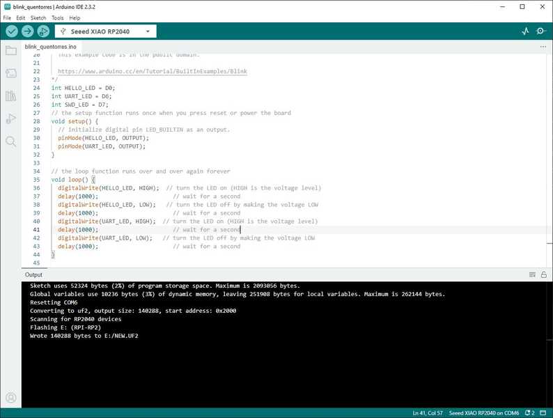
I thought I would try just the UART_LED and see if it worked. I had an error like before, so I checked the communications and COM6 was showing now instead of COM4.
-
I selected COM6 and the program uploaded and worked just fine.
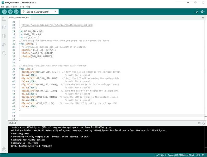
- Now for three LEDs!
/*
  Blink

  Turns an LED on for one second, then off for one second, repeatedly.

  Most Arduinos have an on-board LED you can control. On the UNO, MEGA and ZERO
  it is attached to digital pin 13, on MKR1000 on pin 6. LED_BUILTIN is set to
  the correct LED pin independent of which board is used.
  If you want to know what pin the on-board LED is connected to on your Arduino
  model, check the Technical Specs of your board at:
  https://www.arduino.cc/en/Main/Products

  modified 8 May 2014
  by Scott Fitzgerald
  modified 2 Sep 2016
  by Arturo Guadalupi
  modified 8 Sep 2016
  by Colby Newman

  This example code is in the public domain.

  https://www.arduino.cc/en/Tutorial/BuiltInExamples/Blink
*/
int HELLO_LED = D0;
int UART_LED = D6;
int SWD_LED = D7;
// the setup function runs once when you press reset or power the board
void setup() {
  // initialize digital pin LED_BUILTIN as an output.
  pinMode(HELLO_LED, OUTPUT);
  pinMode(UART_LED, OUTPUT);
  pinMode(SWD_LED, OUTPUT);
}

// the loop function runs over and over again forever
void loop() {
  digitalWrite(HELLO_LED, HIGH);  // turn the LED on (HIGH is the voltage level)
  delay(1000);                      // wait for a second
  digitalWrite(HELLO_LED, LOW);   // turn the LED off by making the voltage LOW
  delay(1000);                      // wait for a second
  digitalWrite(UART_LED, HIGH);  // turn the LED on (HIGH is the voltage level)
  delay(1000);                      // wait for a second
  digitalWrite(UART_LED, LOW);   // turn the LED off by making the voltage LOW
  delay(1000);                      // wait for a second
  digitalWrite(SWD_LED, HIGH);  // turn the LED on (HIGH is the voltage level)
  delay(1000);                      // wait for a second
  digitalWrite(SWD_LED, LOW);   // turn the LED off by making the voltage LOW
  delay(1000);
}
Yay!!! I am having fun now :) Now I will speed it up a bit.
- This time I added constants for the time delays, so I can change the numbers faster.
/*
  Blink

  Turns an LED on for one second, then off for one second, repeatedly.

  Most Arduinos have an on-board LED you can control. On the UNO, MEGA and ZERO
  it is attached to digital pin 13, on MKR1000 on pin 6. LED_BUILTIN is set to
  the correct LED pin independent of which board is used.
  If you want to know what pin the on-board LED is connected to on your Arduino
  model, check the Technical Specs of your board at:
  https://www.arduino.cc/en/Main/Products

  modified 8 May 2014
  by Scott Fitzgerald
  modified 2 Sep 2016
  by Arturo Guadalupi
  modified 8 Sep 2016
  by Colby Newman

  This example code is in the public domain.

  https://www.arduino.cc/en/Tutorial/BuiltInExamples/Blink
*/
int HELLO_LED = D0;
int UART_LED = D6;
int SWD_LED = D7;
int DELAY1 = 500;
int DELAY2 = 500;

// the setup function runs once when you press reset or power the board
void setup() {
  // initialize digital pin LED_BUILTIN as an output.
  pinMode(HELLO_LED, OUTPUT);
  pinMode(UART_LED, OUTPUT);
  pinMode(SWD_LED, OUTPUT);
}

// the loop function runs over and over again forever
void loop() {
  digitalWrite(HELLO_LED, HIGH);  // turn the LED on (HIGH is the voltage level)
  delay(DELAY1);                      // wait for a second
  digitalWrite(HELLO_LED, LOW);   // turn the LED off by making the voltage LOW
  delay(DELAY2);                      // wait for a second
  digitalWrite(UART_LED, HIGH);  // turn the LED on (HIGH is the voltage level)
  delay(DELAY1);                      // wait for a second
  digitalWrite(UART_LED, LOW);   // turn the LED off by making the voltage LOW
  delay(DELAY2);                      // wait for a second
  digitalWrite(SWD_LED, HIGH);  // turn the LED on (HIGH is the voltage level)
  delay(DELAY1);                      // wait for a second
  digitalWrite(SWD_LED, LOW);   // turn the LED off by making the voltage LOW
  delay(DELAY2);
}
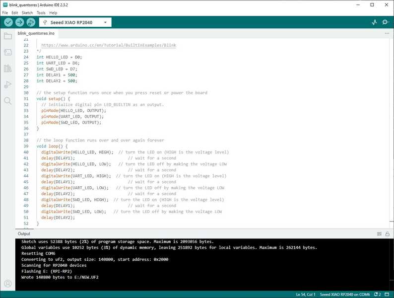
- One last time to make it fun! I changed the delay to 50 milliseconds. Yay!!!
Included ‘hero shot(s)’:
- Included ‘hero shot(s)’:
-
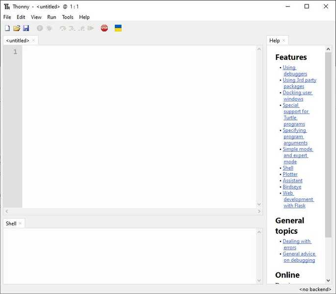
Now on to programming with MicroPython! I will be using Thonny as the IDE. I have a tutorial from Random Nerds Tutorials (RNT). It is focused on the ESP32, but it has some helpful tips. I will also be referring to the tutorial from Instructor’s Bootcamp 2024 - Fab Academy. Together, these tutorials got my LED blinking and here is how I did it.
-
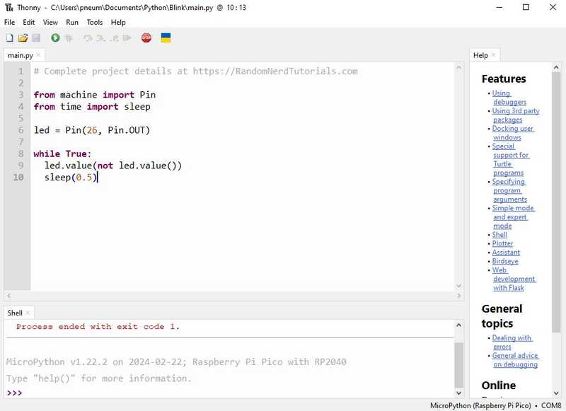
In order to run a python program, I had to load the MicroPython firmware onto the RP2040. I did that using the Thonny IDE. When I opened Thonny the new file is untitled and the lower right corner said
meaning there is no micropython there to run a program.
- So that is the first order of business after plugging in the RP2040. Install the MycroPython firmware on the RP2040. Click on the lower right corner said
and see the below popup.
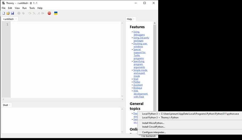
- This window appears.
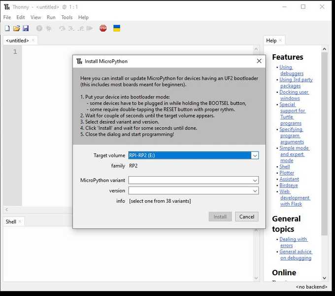
- Click the MicroPython variant dropdown and select Raspberry Pi - Pico / Pico H. As mentioned in the Instructor Bootcamp “select pico as target (pico and xiao-rp2040 act the same)”
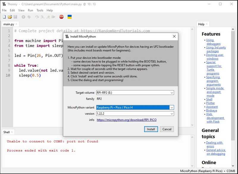
- Click Install
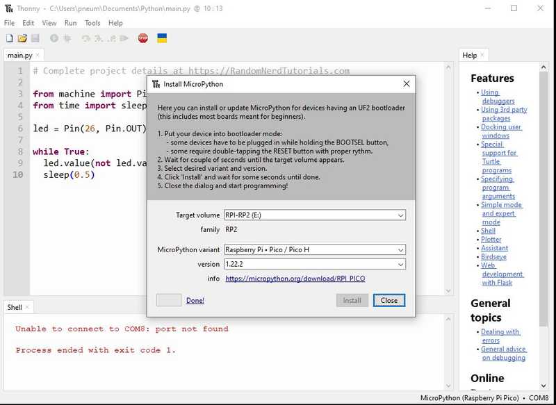
- Click Close
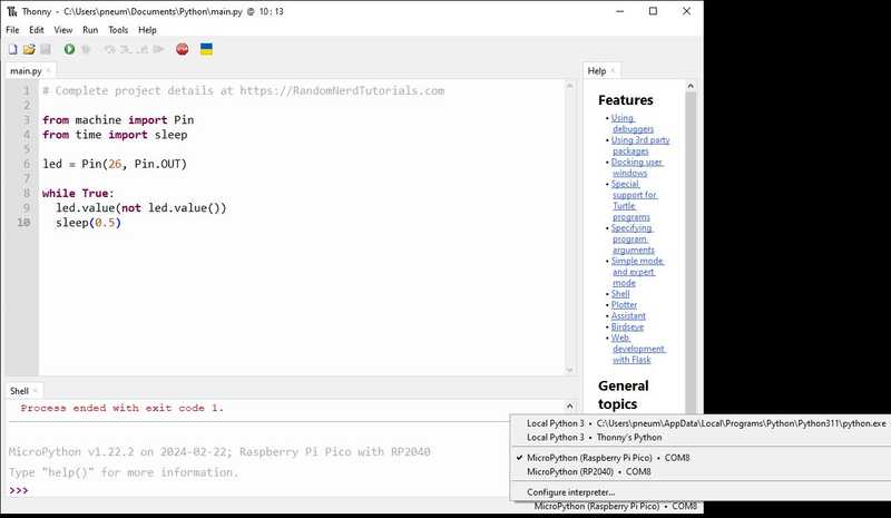
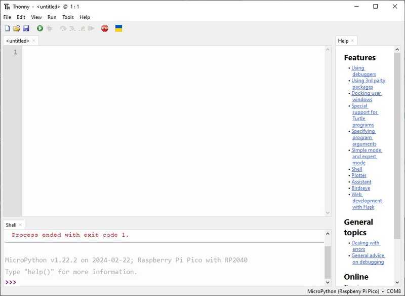
- Click in the lower right corner to establish communications with the MicroPython and you will see the prompt in the lower window as follows.
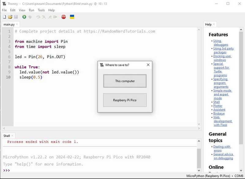
- As I found on RNT, you need to name the file main.py in order to run the file in MicroPython. So Click File > Save as and this is the window that pops up. Click This computer and save it in an identifying project folder, Blink in this case. and this is the main.py file from RNT.
# Complete project details at https://RandomNerdTutorials.com

from machine import Pin
from time import sleep

led = Pin(26, Pin.OUT)

while True:
  led.value(not led.value())
  sleep(0.5)
-
Notice that I put 26 for the pin number for the QuenTorres board.
-
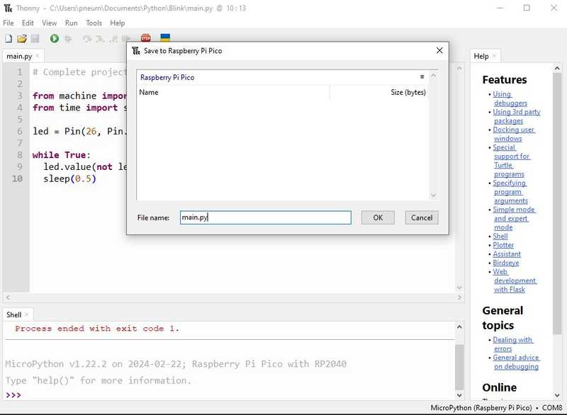
Click File > Save as
- Click Raspberry Pi Pico name the file main.py. Click OK
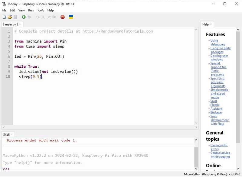
- Click Run current script (F5) and the HELLO_LED blinks :)
Included ‘hero shot(s)’:
- Included ‘hero shot(s)’:
Success!!
During the last cycle I did some experimenting for networking and communications week; I thought this was a good place to demonstrate.
My documentation was left in my notes, so I share them here. The next spiral was using a button on one radio to light a LED on the other radio. Very challenging. There were typos in the code provided on the Arduino Project Hub; https://create.arduino.cc/projecthub/MinukaThesathYapa/controls-a-led-from-nrf24l01-f6937e#widget-comments but I used what I learned from Dejan Nedelkovski to correct the errors. I was able to blink the LED from across the room. YAY!
Research
- During Fab Academy 2019, I visited LCCC Fab Lab this week during our Spring Break to fulfill the requirement in my remote student agreement.

- Found that the 3D Benchy was printed there too :)

- Met Paul and Brigette O’Neill and our instructors Scott Zitek and Chris Rohal. Below photos taken and provided by Paul O’Neill
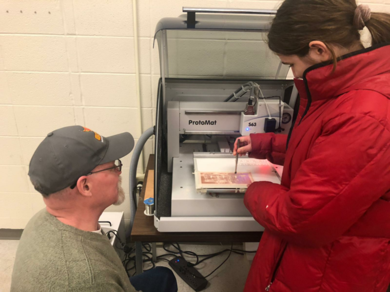

- Proof of presence :)