Computer-Controlled Cutting
This week I learned about parametric design, lasercutting, and vinylcutting. This included:
Unit Description
Group assignment:
- characterize your laser cutter’s focus, power, speed, rate, kerf, and joint clearance.
- Document your work to the group work page and reflect on your individual page what you learned.
Individual assignments:
- Design, lasercut, and document a parametric press-fit construction kit, which can be assembled in multiple ways. Account for the laser cutter kerf.
- Cut something on the vinyl cutter.
Learning outcomes
- Demonstrate and describe parametric 2D modelling processes.
- Identify and explain processes involved in using the laser cutter.
- Develop, evaluate and construct a parametric construction kit.
- Identify and explain processes involved in using the vinyl cutter.
Checklist
Linked to the group assignment page:
- Linked to the group assignment page:
- This is a link to the LCCC Fab Academy 2020 Group Assignment. and this is a link to the LCCC Fab Academy 2022 Group Assignment. Since I was a remote student, I characterized the laser cutter at the GOCAT Fab Lab. The process was similar and I list the results below:
Description: Characterize your lasercutter’s focus, power, speed, rate, kerf, joint clearance and types.
This is a characterization of the laser cutter in my FABCAT Fab Lab. However, I will leave the information afterwards of the laser cutter I used in the GOCAT Fab Lab to show my spiral of learning.
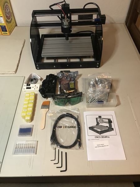
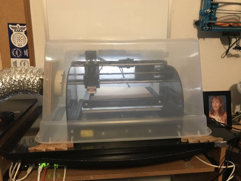
For the Fab Academy, I am required to have a desktop CNC precision milling machine, so I shopped around and discovered a machine that doubles as a laser cutter as well. Meet MySweety as the advertisement shows, it is a 2 in 1 7000mW CNC 3018Pro-M Engraver Machine, GRBL Control 3 Axis Mini DIY CNC Router with 7W Laser Module Kit. I used this machine since the Fab Academy 2022. I constructed it in December 2021.
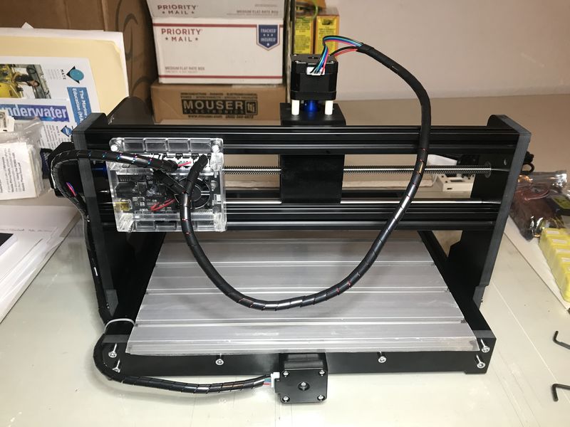
- This is the controller:
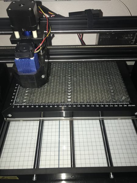
- The laser module is installed:
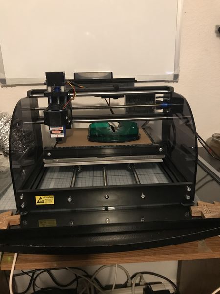
- To make the machine more laser compliant, I added a SCULPFUN Honeycomb Working Table 300x200x22mm, Laser Cutting Honeycomb Laser Bed
| SPECIFICATIONS | |
|---|---|
| Effective Engraving Area | 300 x 180 x 45mm(11.8 x 7.1 x 1.8”) |
| Frame Size | 400 x 330 x 240mm(15.7 x 13.0 x 9.4”) |
| Frame Material | Aluminum+PF |
| Z-Axis Component Material | ABS |
| Spindle | 775 motor, 12V; 24V, 10000r / min |
| Software | GRBL control systems LaserGRBL |
| Rated power | 60W; Maximum power: 120W |
| Step Motor | Fuselage length 34MM,Current 1.33A, 12v.Torque 0.25N/M |
| Drill Bits | Tip 0.1mm ,20 degree , diameter3.175mm. the package includeD 10pc. |
| Support System | Windows XP, Windows 7 32/64 bits, Windows 8, Windows 10 |
| Power Supply | 24V/5A |
| Laser | 12V/7W, Wavelength: 450nm (Blue light) |
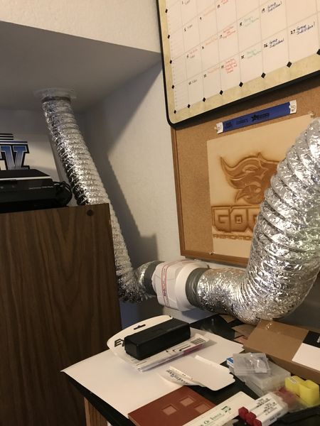
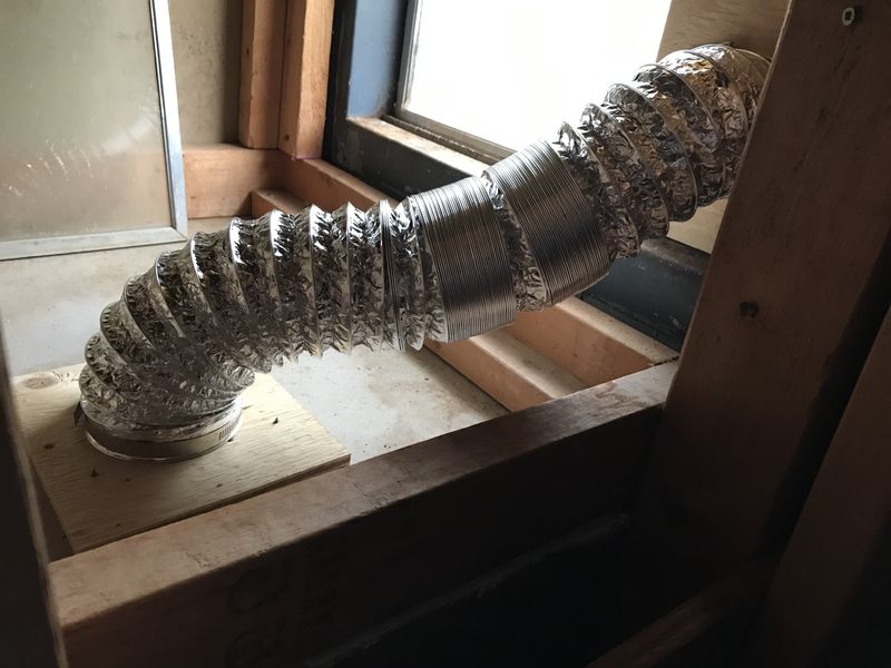
- For safe forced ventilation, I designed and constructed a duct system using a SEAFLO 4” in-Line Marine Bilge Air Blower 12V 270 CFM and Aluminum Foil Dryer Hose with Dryer Vent Quick Release - Two-Piece Dryer Hose Quick-Connect, Twist & Lock Tight, that Fits 4 Inch Tubes. This ventilation hooded system vents outdoors.
- SEAFLO Blower and ducting:
- Outdoor ventilation path:
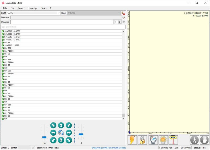
- The first step before cutting is to focus the laser; I use LaserGRBL to connect and communicate with MySweety. The newer versions do not have the Z-axis control built into the interface, so I use v4.8.0 which has the Z-axis control interface and added some custom buttons to control the laser for focusing. Now I have the buttons the newer version has, but I also have the ability to control the Z-axis.
- Focusing (from the CNC3 User Manual v1.2)
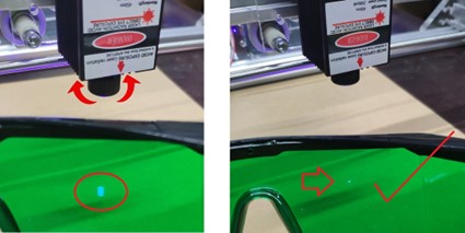
CAUTION: You must wear safety glasses provided by vendor as shown in the image below to protect your eyes from the laser…EVEN THOUGH IT IS AT LOW POWER DURING FOCUSING.
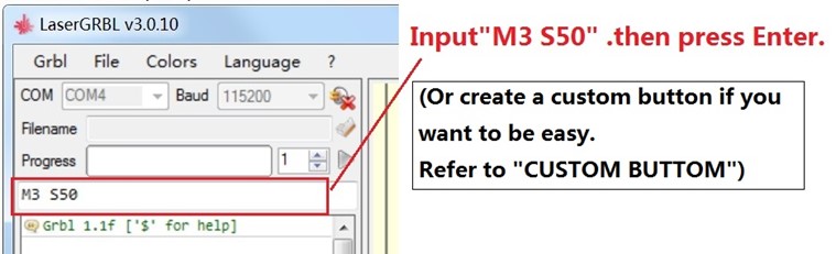
- The laser will be turned on with low power model. Then Rotate the lens to minimize the spot.
-
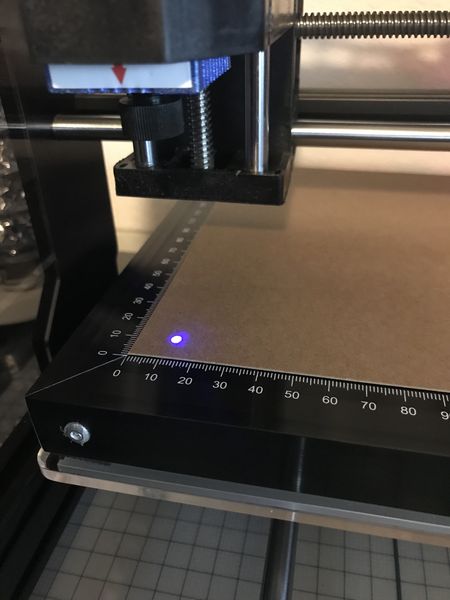
I adjusted the laser module height first by loosening the clamp screw and sliding the module as a coarse adjust with the laser on low power. Next I adjusted the lens by twisting as in the image. When the dot was smallest, I knew I had a good focus. I tightened the clamp screw and then adjusted the Z-axis in 10mm increments to observe the waist of the laser. 20mm up shows a definite widening of the laser.
-
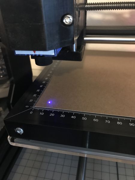
This is the focused laser:
- This is 10mm out of focus:
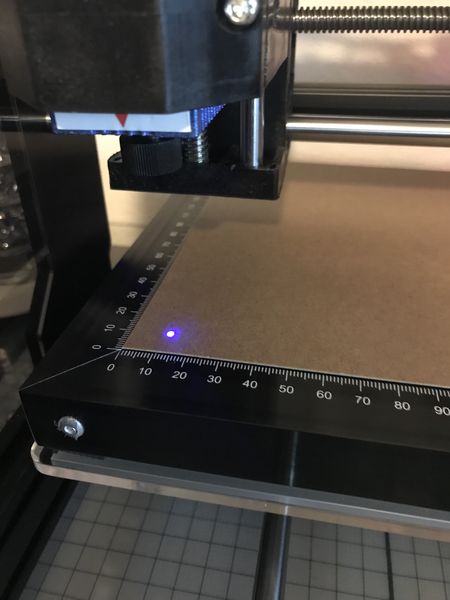
- This is 20mm out of focus:
-
I have much to learn about laser cutting with MySweety at 7W. The laser I had in the GOCAT Fab Lab was 75W, so I was spoiled. What I am finding is the amount of time it takes. What would have taken 1 minute at 75W takes 1 hour with 7W.
-
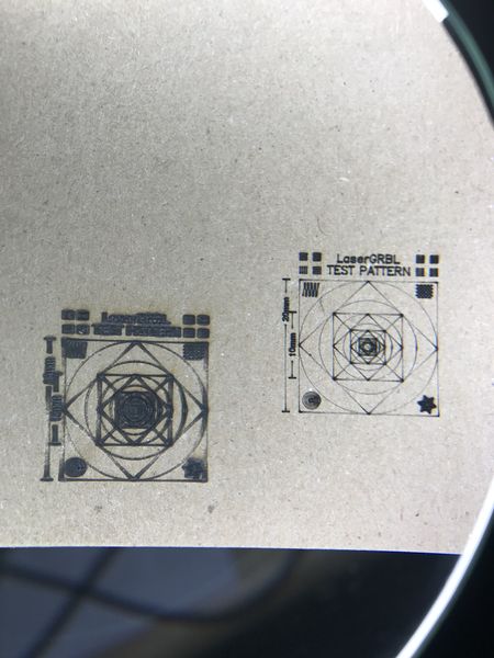
After focusing my laser, I used the laser accuracy test file at the LaserGRBL website to try it out.
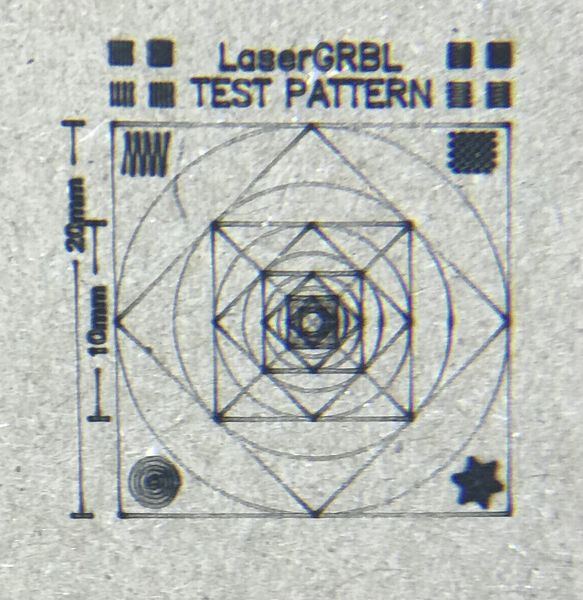
- This is my first try with thin cardboard:
- A magnified view:
- So then I tried it with some hardwood:
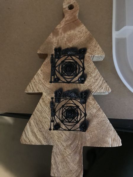
- This is after I discovered the difference between cutting and etching setting in the software:
- This is the best result after turning down the power:
-
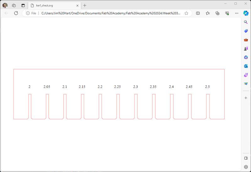
The next spiral was to make a kirf test comb. I searched the Fab Academy and found some help from Fab Lab Kamakura Thank you! I will repeat the website Kerf Check Parts Generator
-
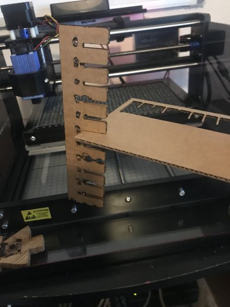
I used the settings in the page for the start of 2.5 mm, -0.05 mm, and loop 11 times. The next image shows the kerf test after I added chamfer to it using Adobe Illustrator. As noted below, I had to scale the image by 35% to obtain the correct size in the LaserGRBL software:
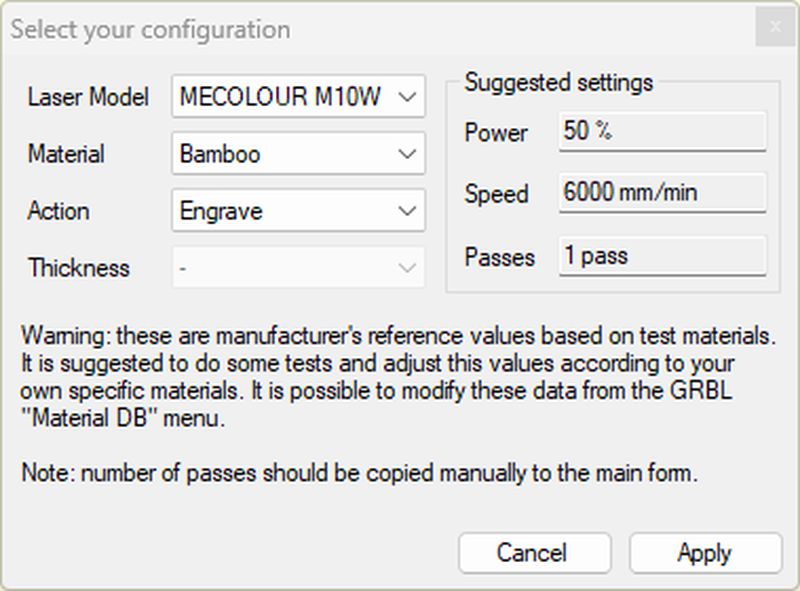
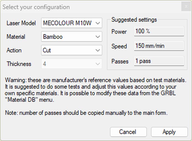
- The first job was to etch the numbers and then cut, so I chose the following settings:
-
I did not have the exact match for the laser that I had, so I decided that a 10W setting would result in a more conservative result. As you will see in the images, I have a few more interations to perfect this process.
-
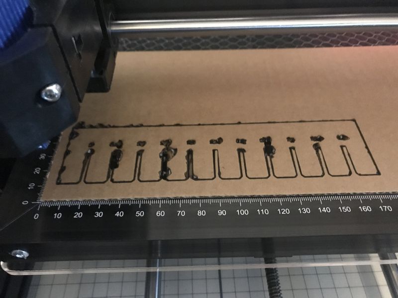
This is the front of the kerf test comb:
- This is the back of the kerf test comb:
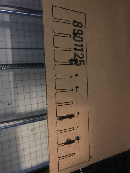
- I was able to use the test to find that the best fit was in the middle:
-
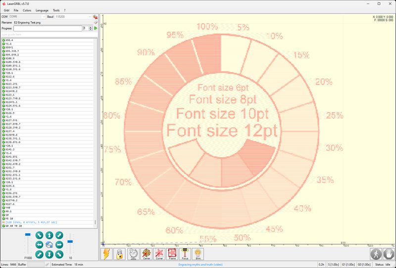
To be honest, this was very discouraging, but I was learning :) So I decided to try a raster greyscale test that I learned about in a tutorial by JD Designs. The file I used is available through his YouTube channel.
-
An afterglow discovery from James Dean was the introduction to Graham Bland who James apparently learned from and made an abridged version of Graham’s experiences. You can find his files, mentioned and used by James Dean in the tutorial, here. This will also provide you the “Introduction to CNC for the Total Novice - Setting up a Laser” that I am using to further my knowledge.
-
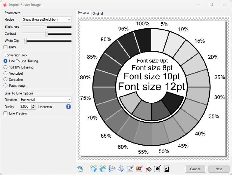
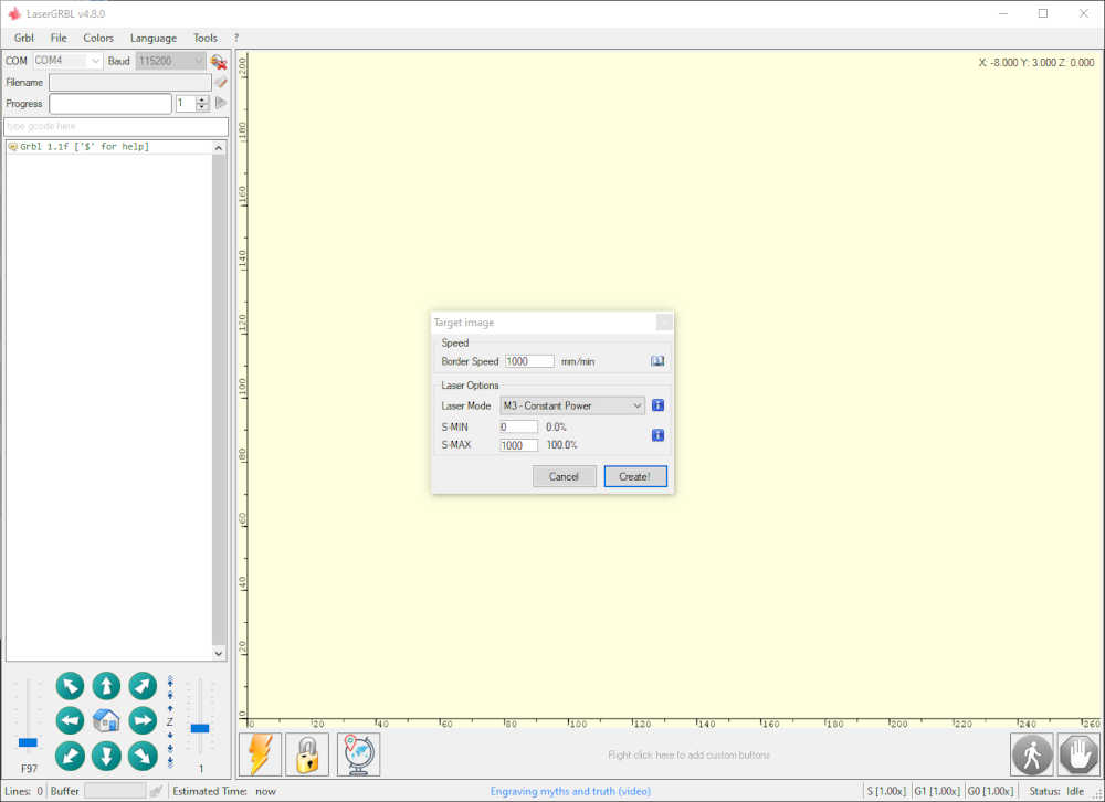
This is the import dialog box to make adjustments as described in the tutorial. I used the default settings for my first attempt:
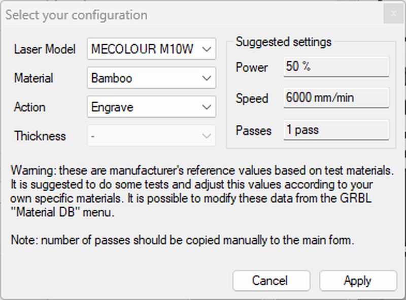
- This is the laser setting dialog box:
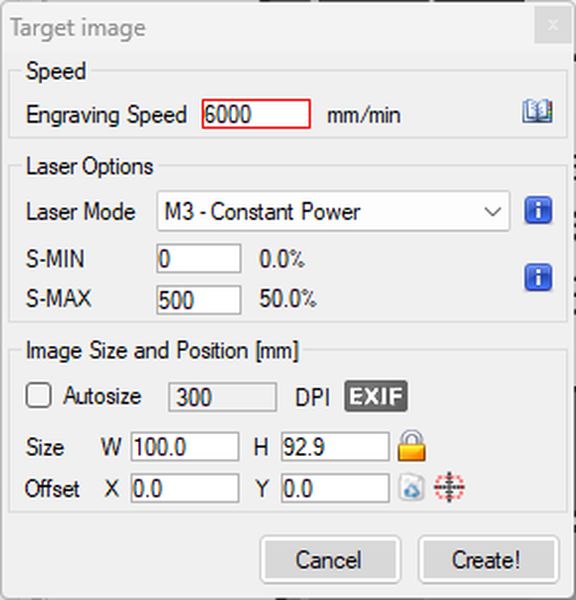
- And the Target image settings before creating the g-code:
- This is the screen just before sending to the laser:
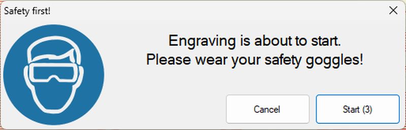
- And the nice warning prompt before the laser starts etching:
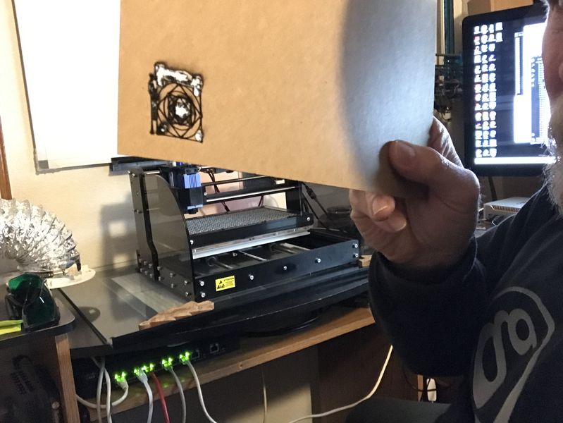
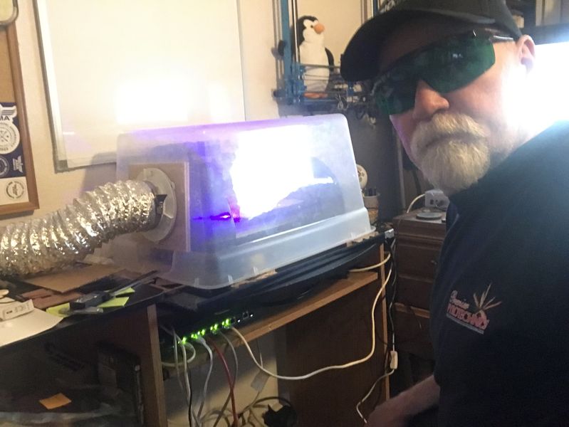
- This is me during the etching with safety glasses on and exhaust sytem running:
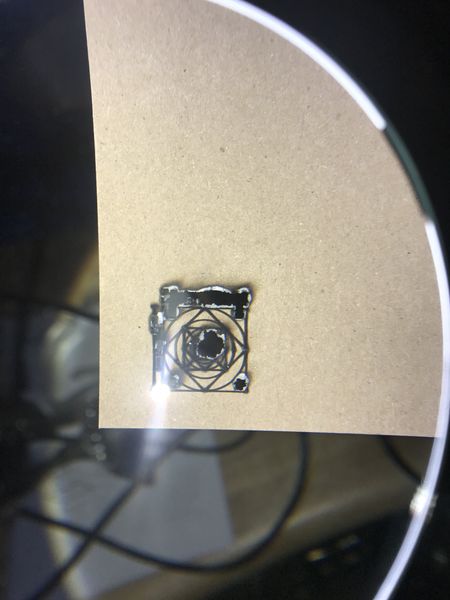
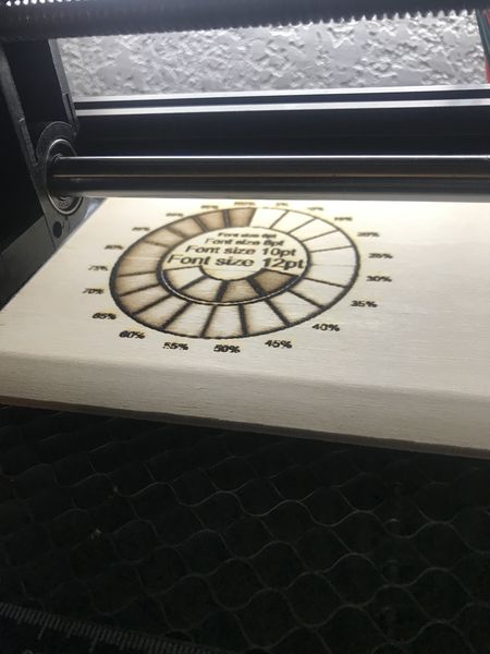
- This is the final product:
-
To get a better grip on my 7W laser, I ooked for a better tool to cut/etch so I could control the power and speed; in my searching, I found Samcraft with his tab @Samcraftcom. He has some free stuff, but I really liked his Lightburn Test Pack so I bought it to help both of us. Now I need to learn about Lightburn.
-
I think Lightburn is cool because of their logo, but the software is cool too. I also found a friend in Fab Lab Barcelona who uses it too :) Thanks Kurt Van Houtte!
-
So I got some more help from James Dean Designs. Such a great video of the software!
Previously at the GOCAT Fab Lab
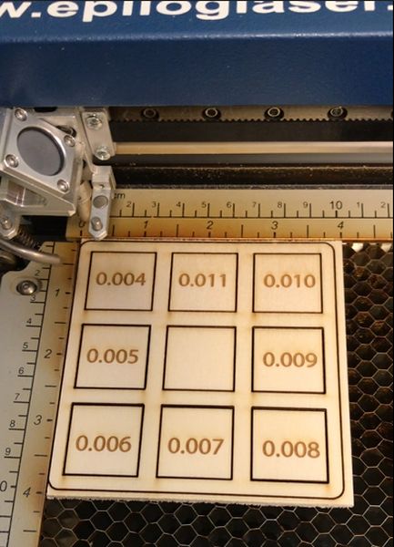
- This is the kerf test I did in the GOCAT with the Epilog Laser Cutter:
- This is a better picture of the final result:
Epilog Helix 24-75W has a 24”x18” cutting table. I use a High Flow Portable Floor Sentry Filtration system, Includes CFP, HEPA and 22LB Carbon filters. I have a fire blanket hanging on the filtration unit for emergencies.
Focus: The focus can be controlled manually or automatically. In manual mode a measuring device is used during adjustment, and then removed. In automatic mode, a plunger senses contact with the material surface; the table automatically adjusts based on the plunger input.
Power, Speed, Rate: Epilog Helix has a table of Suggested Material Settings in Appendix B; these parameters are adjustable on the physical control panel as well as through software settings.
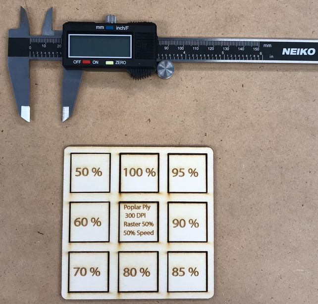
I used the below Kerf Gauge.
Using the research on the Kerf Gauge, I intend to reproduce the kerf gauge in Adobe Illustrator and measure the kerf of the Epilog Helix 75w Laser Cutter.
Materials: Using current laptop, internet connection, and Epilog Helix 75w Laser Cutter. Used poplar 1/8” plywood to test the kerf gauge.
Problems: I made the kerf gauge, but line thickness did not make a difference. I discovered that the lines between .001 and .005 will cut, but the power is determined by the laser settings. Additionally, I had multiple lines overlayed in Illustrator and the laser cutter dutifully cut them; making multiple passes and invalidating the test. I discovered this by reviewing the video. I will redo this test to get a more accurate characterization of the Epilog Helix.
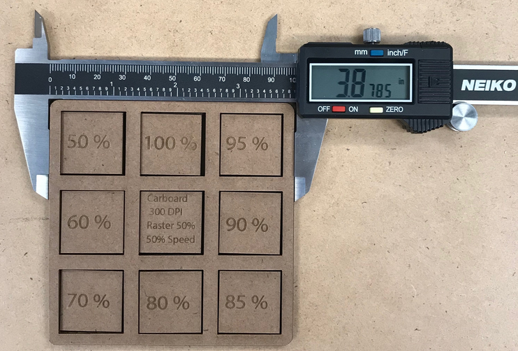
Corrections: I changed the power setting by 10% from 50% up to 100% and found a noticeable difference. I measured with a digital caliper and found a .030 difference from 50% to 100%
| Material | % Power | Measurement (inches) | Kerf (inches) |
|---|---|---|---|
| Poplar Ply | 50 | 0.9955 | 0.0045 |
| Poplar Ply | 60 | 0.9925 | 0.0075 |
| Poplar Ply | 70 | 0.9890 | 0.0110 |
| Poplar Ply | 80 | 0.9895 | 0.0105 |
| Poplar Ply | 90 | 0.9870 | 0.0130 |
| Poplar Ply | 95 | 0.9875 | 0.0125 |
| Poplar Ply | 100 | 0.9895 | 0.0105 |
| Cardboard | 50 | 0.9875 | 0.0125 |
| Cardboard | 60 | 0.9870 | 0.0130 |
| Cardboard | 70 | 0.9860 | 0.0140 |
| Cardboard | 80 | 0.9855 | 0.0145 |
| Cardboard | 85 | 0.9840 | 0.0160 |
| Cardboard | 90 | 0.9835 | 0.0165 |
| Cardboard | 95 | 0.9830 | 0.0170 |
| Cardboard | 100 | 0.9830 | 0.0170 |
Explained how you created your parametric design:
- Explained how you created your parametric design:
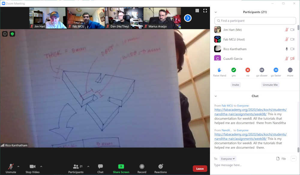
After attending the Global Open Time session and learning from Rico Kanthatham and Dan Meyer, I modelled and attempted to parametrically design the seat of the carboard kayak I am designing for my Final Project. The majority of the parts for the kayak will be parametrically designed in a future spiral 💫 One spiral at a time…😎
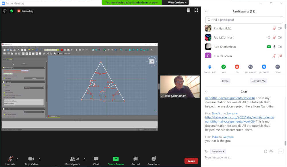
This is what I accomplished in the FreeCAD tutorial on parametric design
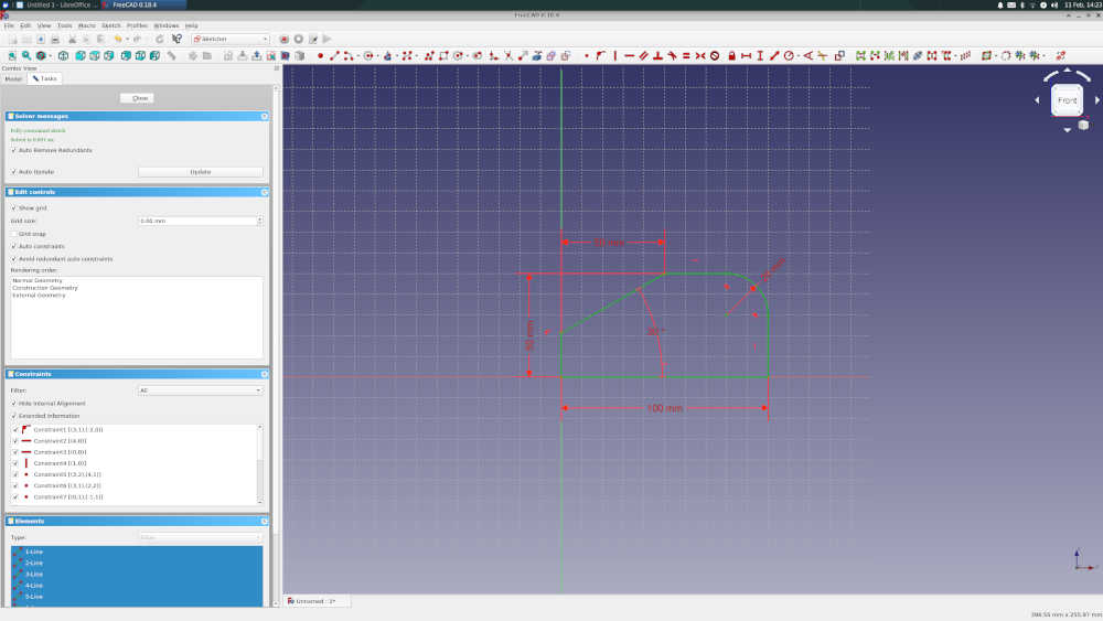
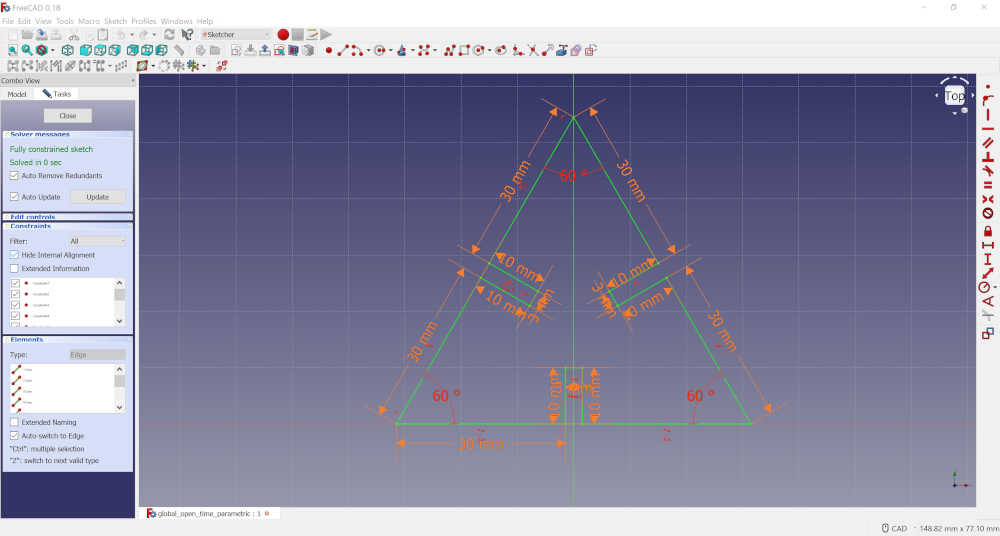
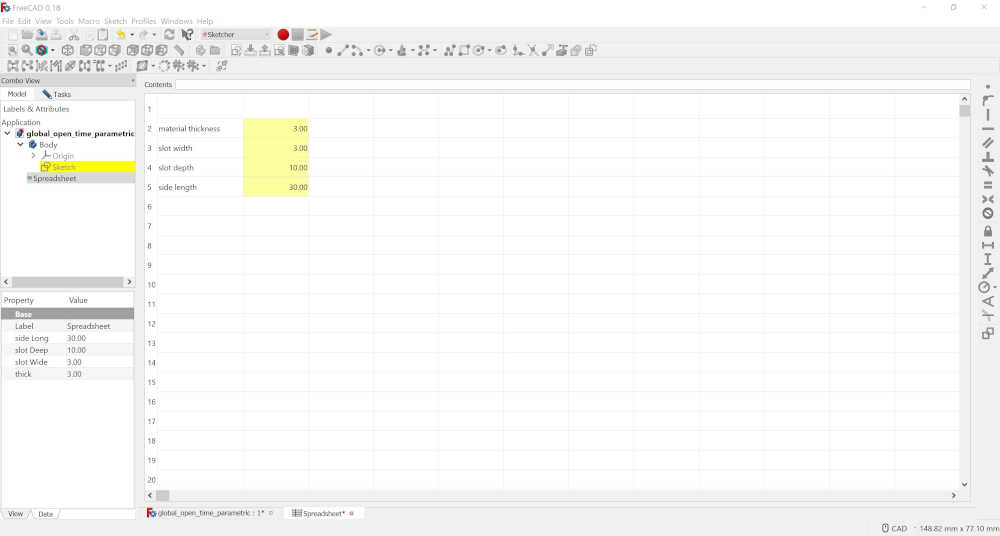
With the guidance of Rico and the skill set obtained from the FreeCAD tutorial, I was able to design a fully constrained parametric triangular part for the press-fit construction kit. I made a triangle using the line tool, then made a coincident constraint to the end points. Then I added slots in the center of the sides with width and length constraints as well as perpendicular to the side. I added an angle constraint of 60 degrees. The spreadsheet of parameters included: material thickness, slot width, slot depth, and side length.
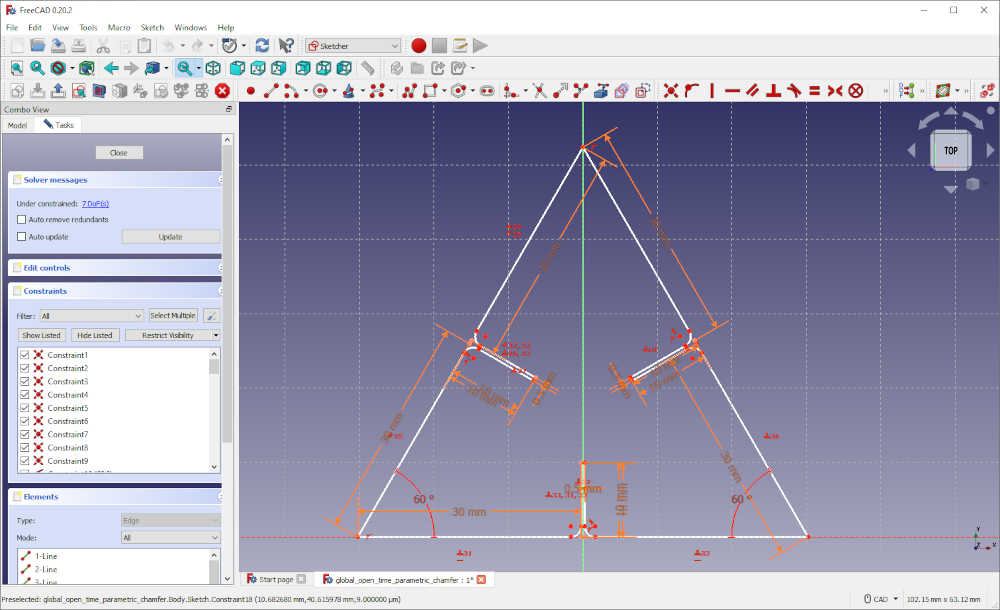
After adding the parameter for the thickness of my carboard material, I added chamfer to the edges where the parts would interface. This image shows the changed slot size as well as the arcs for the chamfers.
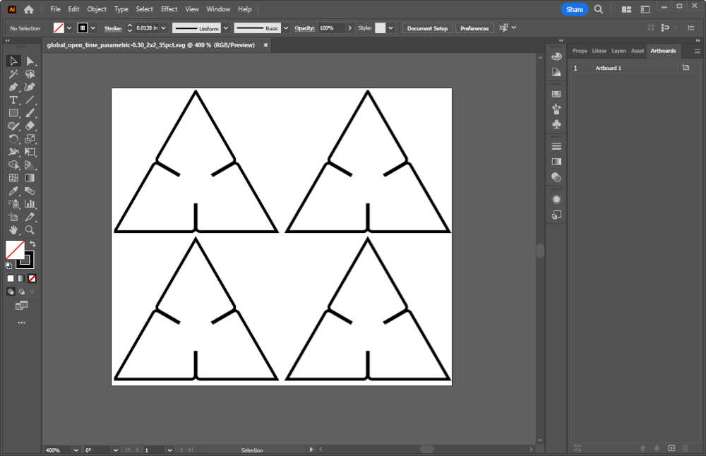
I exported the parmetric triangle from FreeCAD as a SVG file and opened it in Adobe Illustrator. Using the Repeat Tool, I made a 2x2 matrix and transformed it to 35% size. (This took many iterations to get the scaling correct.) I discovered that the reason is in the Adobe Illustrator settings that have not been resolved as of the Fab Academy 2024. I found the discussion in Adobe Community with some guidance. Turns out that I did the right thing to correct it since I want to continue using Adobe Illustrator.
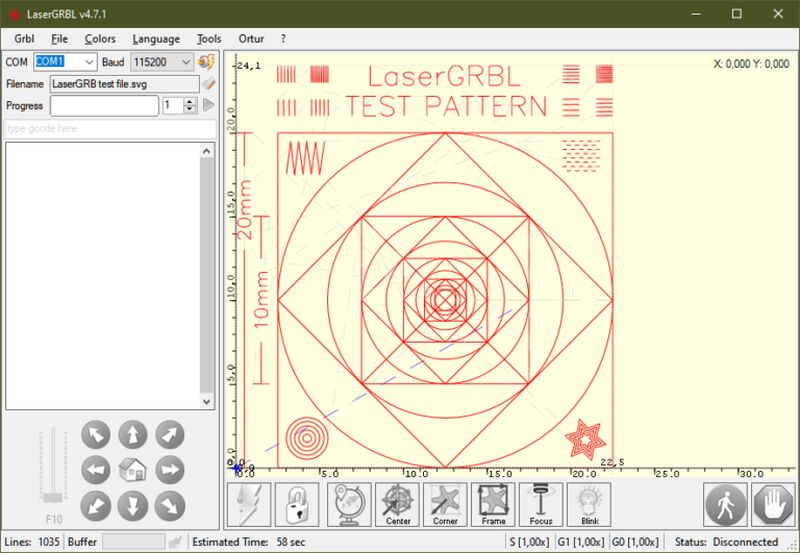
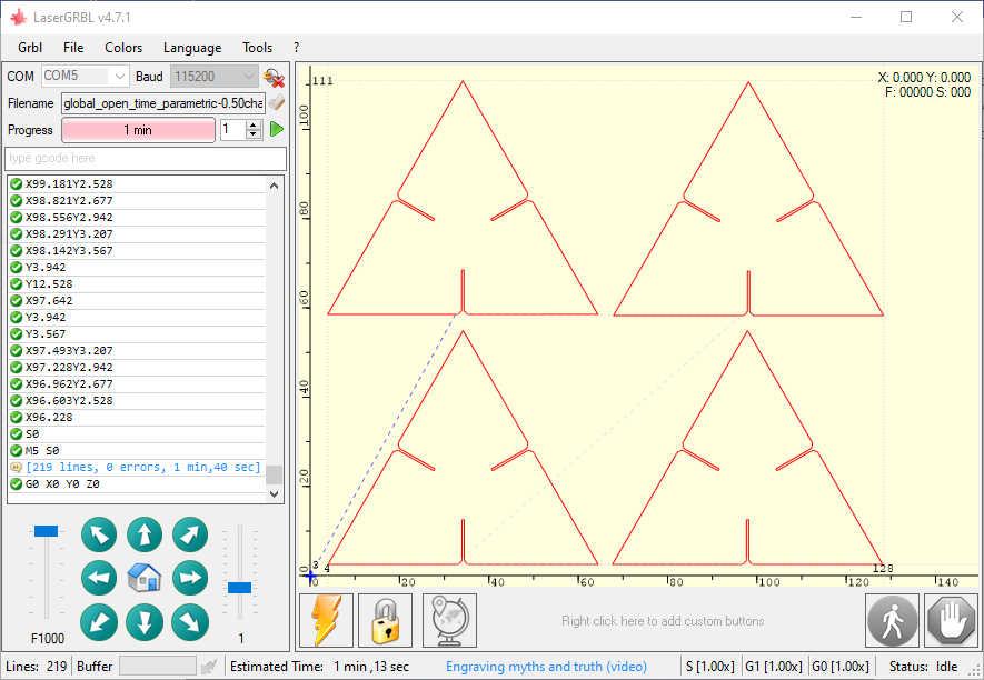
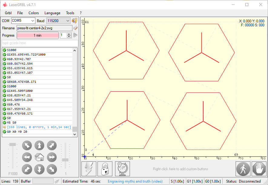
After the image was properly scaled, I opened it in LaserGRBL in preparation for cutting. File >> Open File >> Select global_open_time_parametric-0.30_2x2_35pct.svg >> Open >> When Target Image opens, you have the option to select various settings; including the laser you have and the material you will be etching/cutting. >> Create!
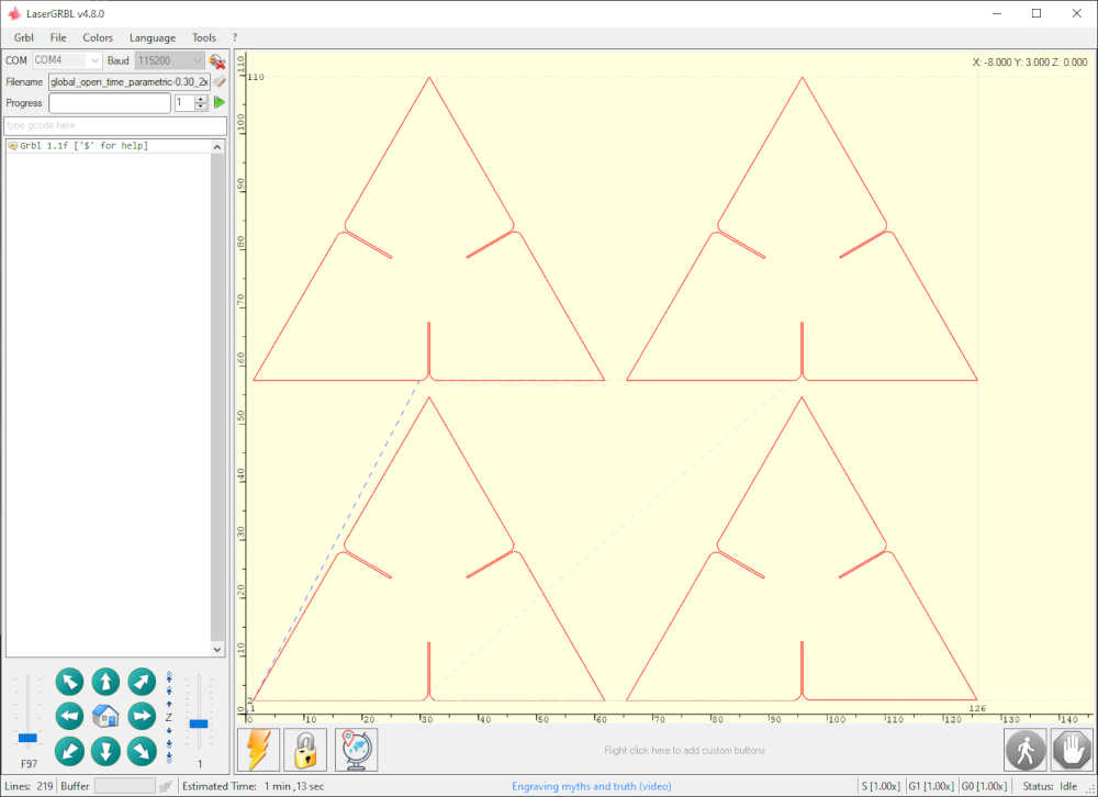
I sent this job to the SweetyLaser3018 and this is the output:
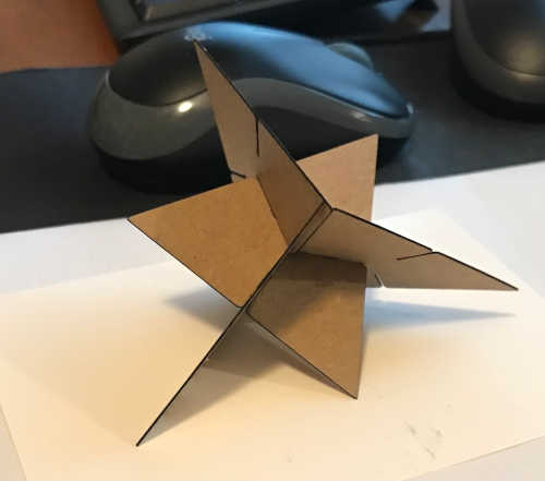
In a previous spiral, I modeled a hexagonal top to tie the ends together and laser cut those. Below is the image of the first parametric triangle and the tops that were modeled and cut:
Included hero shots of your results:
- Included hero shots of your results:
These are my hero shots for this cycle:
This is what I plan to add parameters to for my cardboard boat final project
Documented how you made your press-fit construction kit:
- Documented how you made your press-fit construction kit:
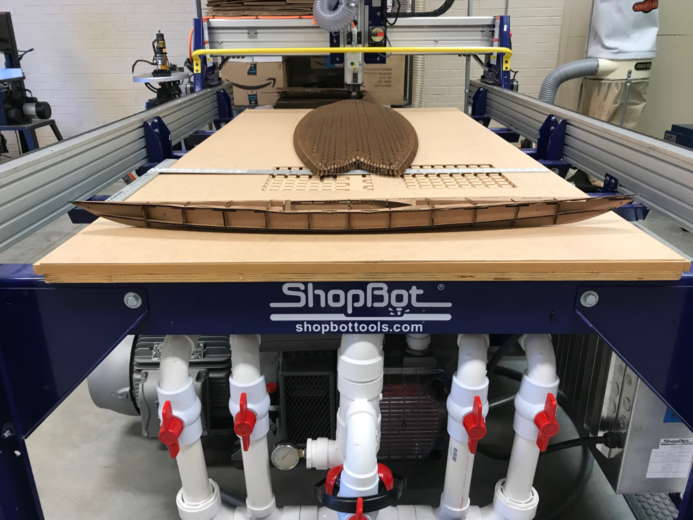
I laser cut and press-fit a cardboard surfboard and a cardboard kayak. The cardboard surfboard was from the original scale whereas the cardboard kayak was 1/4 scale:
I always wanted to be able to make a cardboard surfboard. Thanks, Mike Sheldrake! Cardboard Surfboards I will use this as a prototype for my final project. I’ll cut a 5‘10” Fish when I get back to the GOCAT Fab Lab.
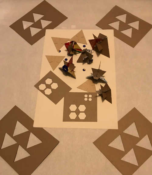
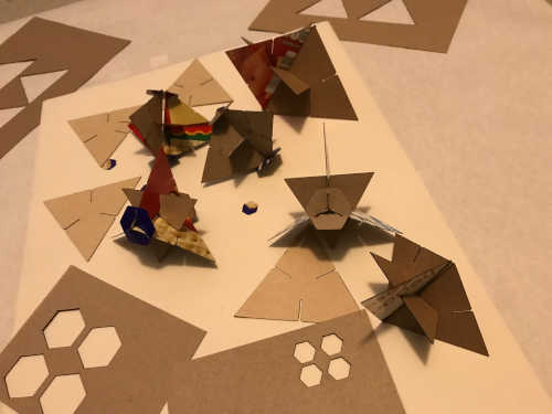
This is an image of all of the press fit parts after cutting in the lasercutter:
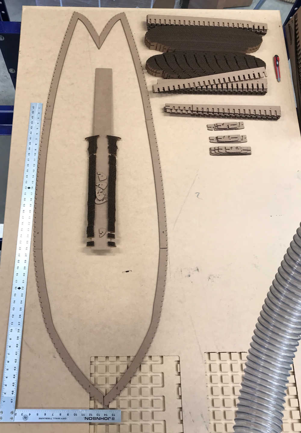
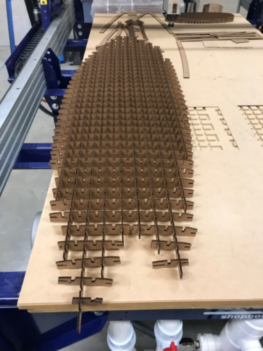
This is the surfboard with the stringers forward to aft and the first set of ribs (port to starboard) installed. I cut the parts from 4mm cardboard. There were 20 sheets of 610mm x 305mm cardboard; they were salvaged from the flood. I cut the rough edges off and made nice pieces to cut the parts from. The laser power was set at 50% and the kerf was perfect for the press-fit construction. I followed the directions given by Mike Sheldrake step-by-step. I will video the next time I assemble 💫 One spiral at a time…😎
Included hero shots of your results:
- Included hero shots of your results:
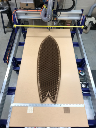
This is the complete surfboard before fiberglassing. The second set of ribs are installed with the rails attached. Ready for glass!
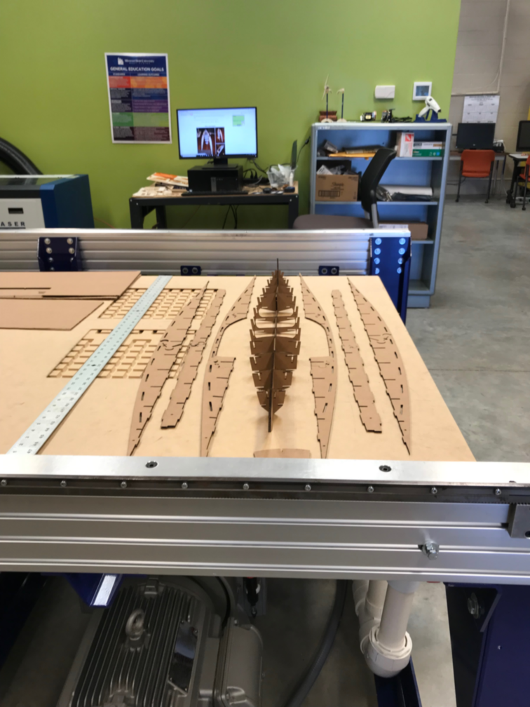
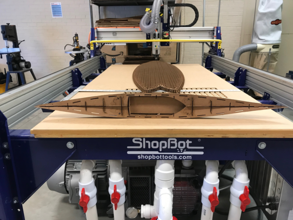
- This is a prototype of a cardboard kayak
Documented how you made something with the vinyl cutter:
-
Documented how you made something with the vinyl cutter:
-
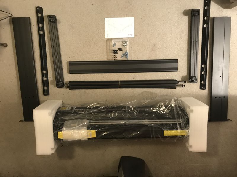
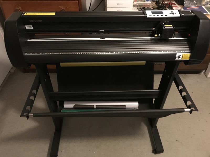
For the Fab Academy, I am required to have a vinyl cutting machine, so I shopped around and discovered a machine that doubles as a plotter as well. Meet Vevor KI-870 Cutting Plotter as the advertisement shows, I have the Vinyl Cutter 34Inch Bundle; which includes Signmaster Software to make signs. I have used this machine since the Fab Academy 2022. I set it up in December 2021 and used it for Wildcard Week in Fab Academy 2023.
-
Here is the setup process:
| SPECIFICATIONS | |
|---|---|
| Max Paper Feed | 34.3 in / 870 mm |
| Max Cutter Width | 30.7 in / 780 mm |
| Cutter Pressure | 10 - 500 g |
| Cutting Speed | 10-800 mm/s |
| Memory | 2 MB |
| Repetition Accuracy | 0.0004 in / 0.01 mm |
| Product Size | 40 x 20.4 x 41 in / 102 x 52 x 104 cm |
| Net Weight | 34.17 lbs / 15.5 kg |
- Please take a look at my work from Wildcard Week Fab Academy 2023
Previously at the GOCAT Fab Lab
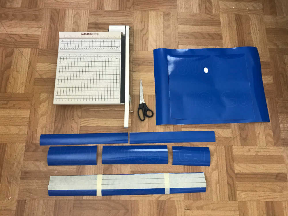
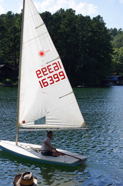
I cut the boat number for my Laser sailboat with the Roland CAMM-1 GS-24 Vinyl Cutter.
Using Roland CutStudio
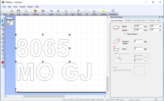
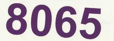
The weeded boat number using purple because it was in the vinyl cutter. This was a test.
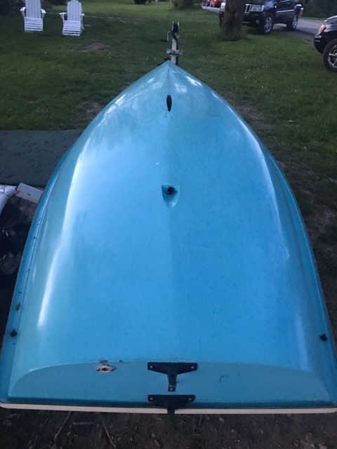
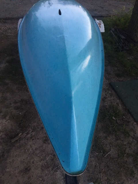
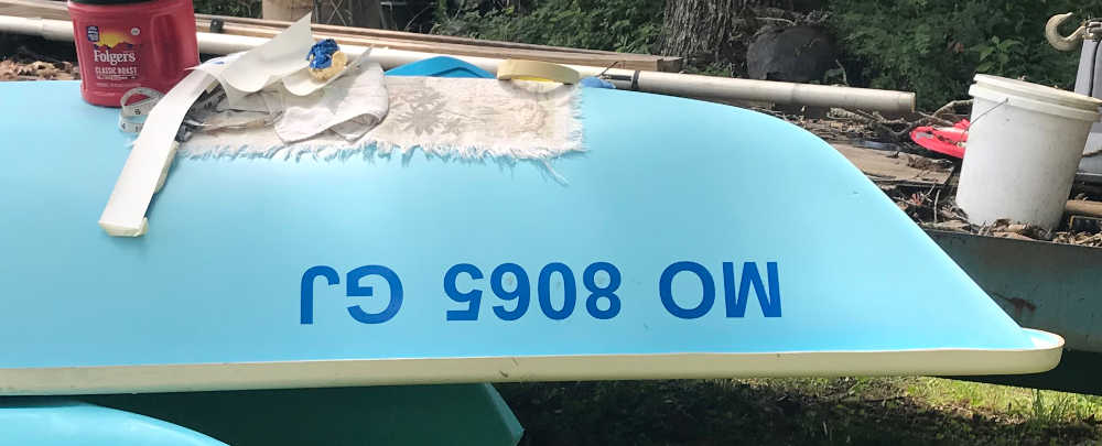
These are the final results using blue vinyl to be applied to Little Blue after I gelcoat.


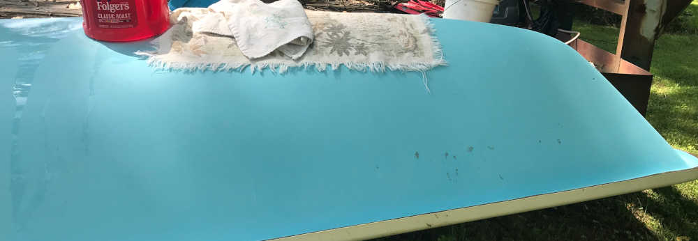
The Little Blue Sailboat ready to be numbered
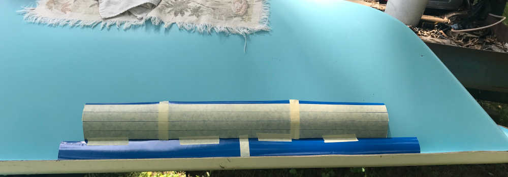
Applying the sailboat numbers:
Preliminary layout
Surface preparation
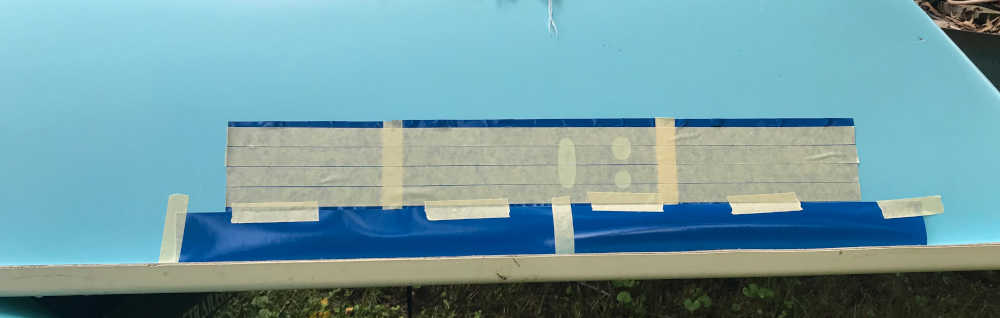
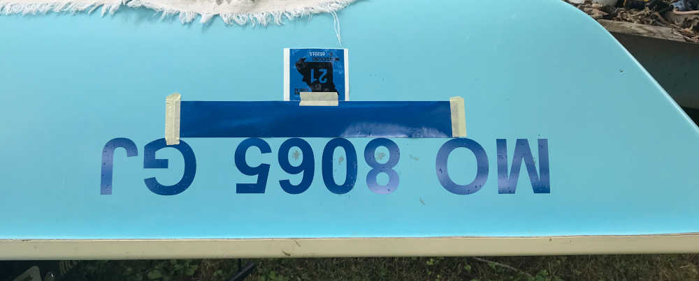
Alignment
Backing removed and vinyl applied
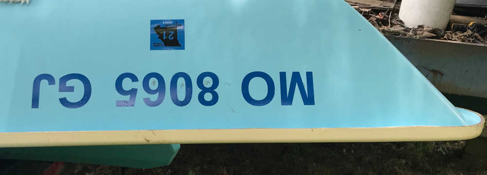
Weeded after application
Aligning the license sticker
Ready to get underway!
Included hero shots of your results:
- Included hero shots of your results:
On the lake!
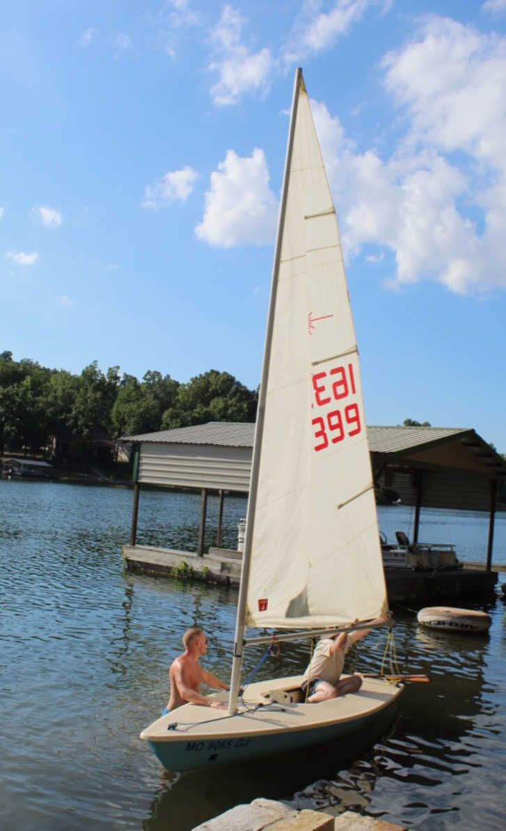
Underway on wind power!
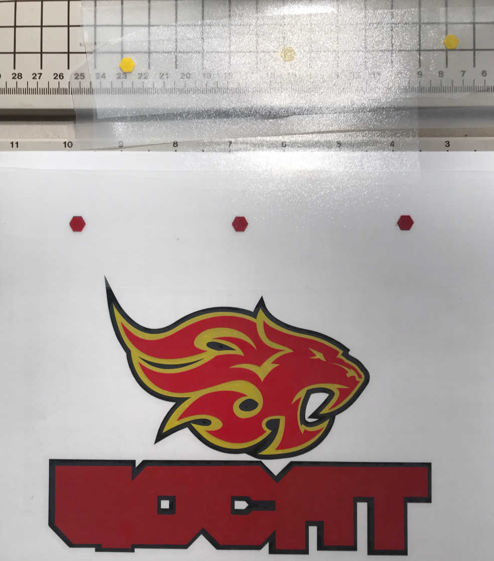
With the next spiral, I made a GOCAT Fab Lab License Plate for my truck. You can read about the design artist and further development in CAD Week
This process used Adobe Illustrator with the Roland Cut Studio Extension
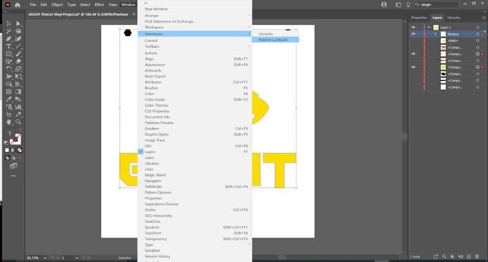
First layer
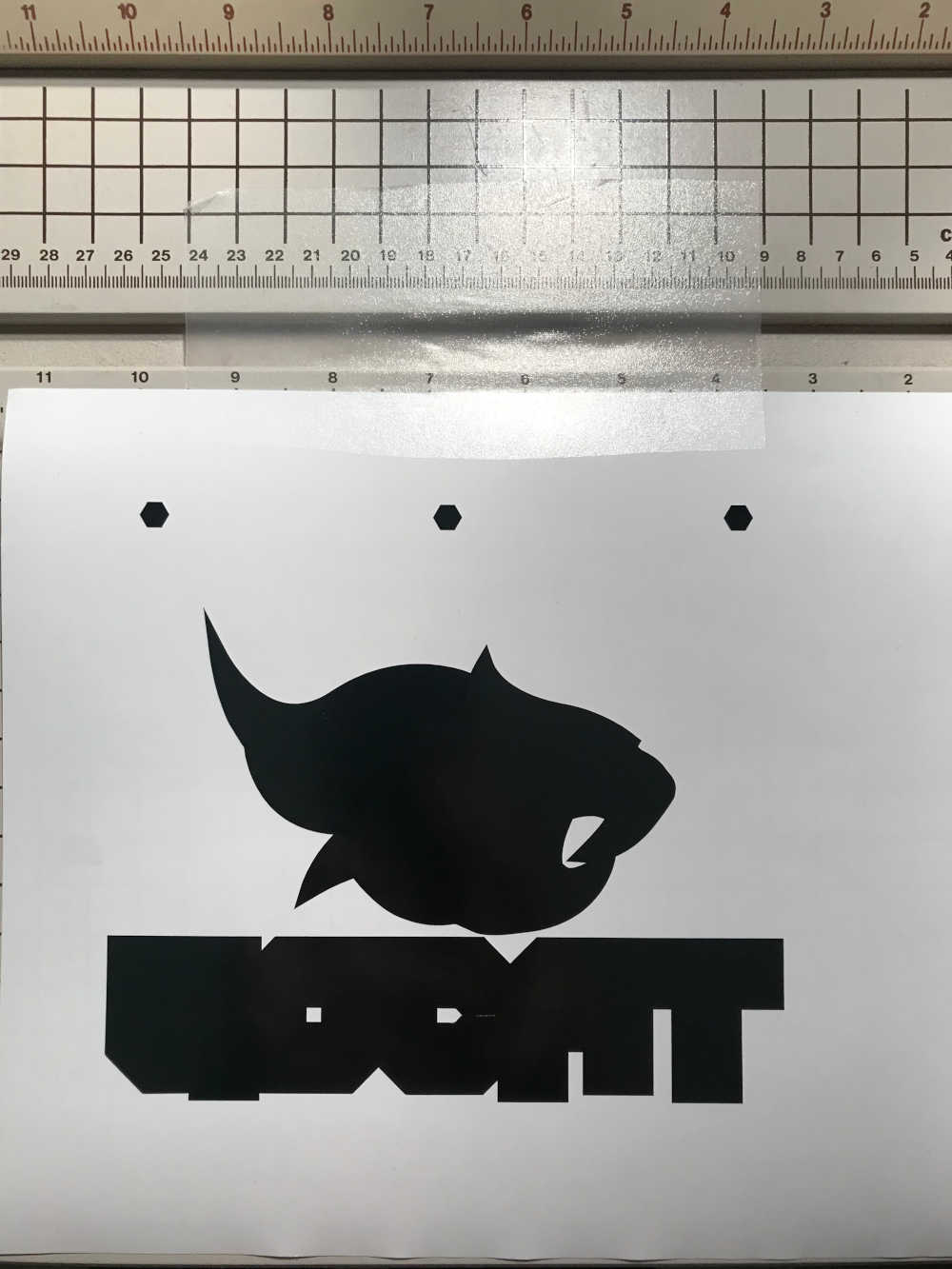
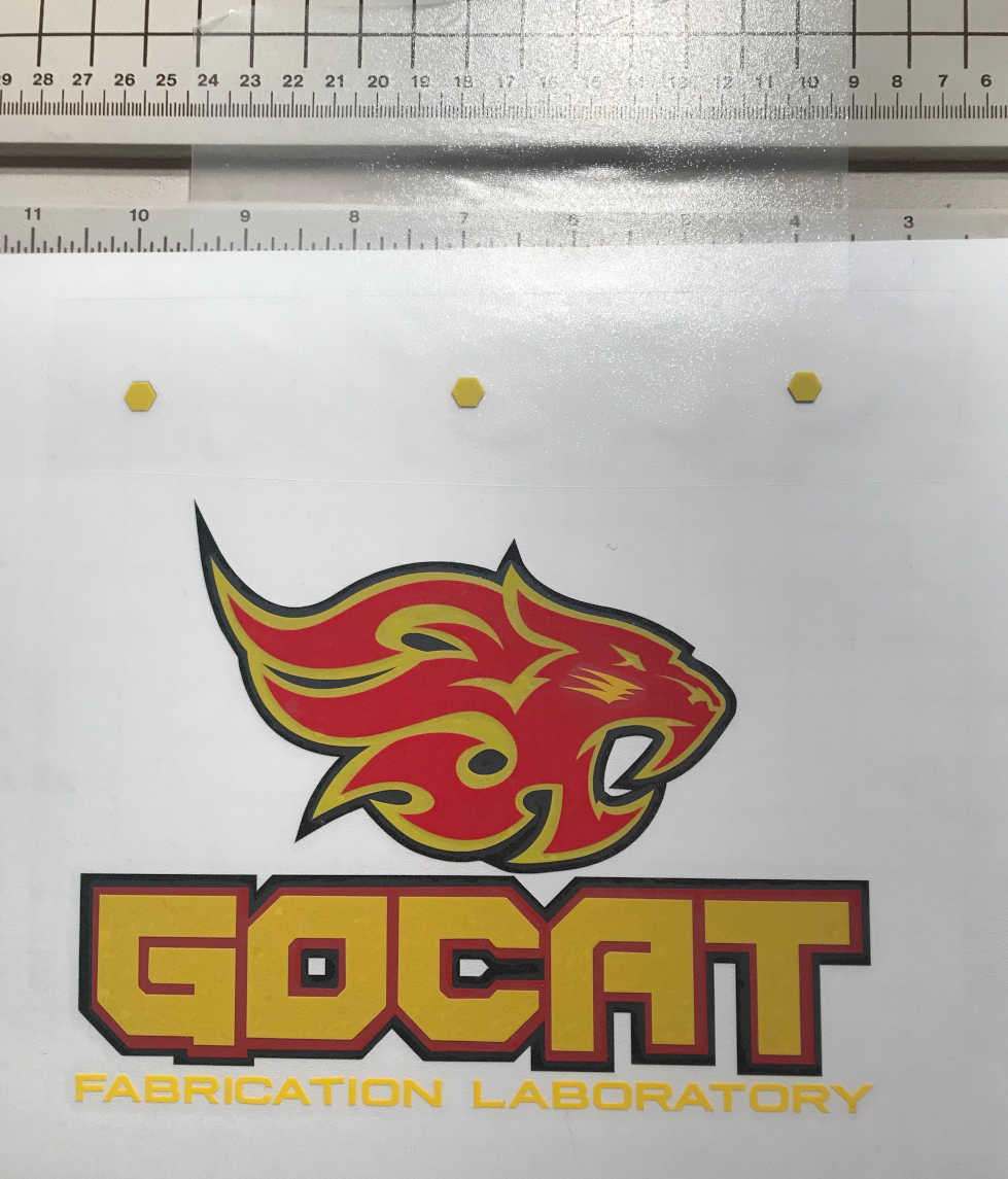
Second layer
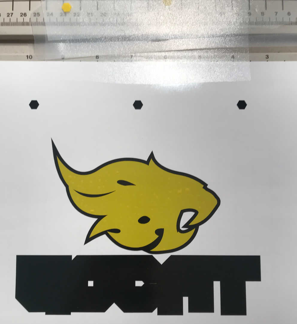
Third layer
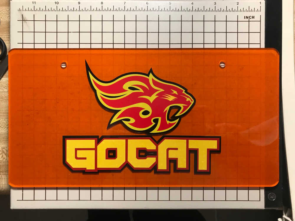
Fourth layer
Applied to acrylic
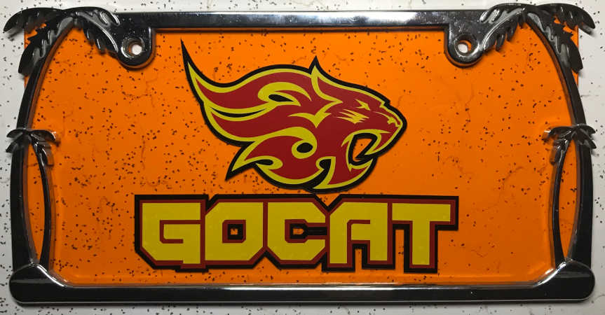
Included hero shots of your results:
- Included hero shots of your results:
Success!
This is a continuation of the Computer-Controlled Cutting week in Fab Academy 2021
-
characterize your lasercutter’s focus, power, speed, rate, kerf, and joint clearance
-
document your work
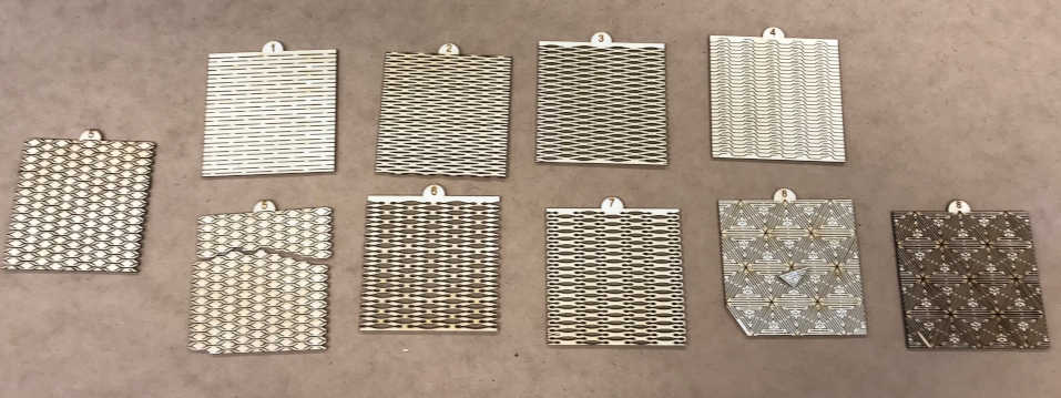
I wanted to experiment with flexible wood, so I downloaded the example from Trotec’s site. This link was shared through Global Open Time: Putting waves in rigid sheet materials with the laser cutter
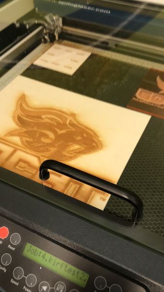
I had an interesting visit in the GOCAT Fab Lab during National Robotics Week 2021. I used the Epilog Helix to engrave bats for our visitors. Although I did not present the XY Plotter laser upgrade during Machine Week, I did demonstrate the value of a laser engraver.
This is a continuation of the Computer-Controlled Cutting week in Fab Academy 2022
-
Since I am running my Fab Lab on a Raspberry Pi 4 with 8 Gb of RAM, I will document the process of going from using Inkscape to design a birthday card to vinyl cutting and laser cutting the materials to make the birthday card.
-
Inkscape is already installed, but I need to add Inkcut to my toolkit. I followed the instructions for installing in Linux here Installed successfully and added Inkcut extension to Inkscape. Unfortunately Inkcut did not startup correctly. I did a search for the error “Sorry, an error prevented Inkcut from starting” here At the end of the thread, after others abandoned the problem, Coogle listed the line “pip3 install pyqtgraph==0.11.1” that seems to work :) Onward and upward!
-
I found a good YouTube Tutorial: Using Vevor Ki-870 Cutting Plotter with Linux here To configure the device, we must use the SeikiTech SK-870T driver.
This is a continuation of the Computer-Controlled Cutting week in Fab Academy 2024
- Instead of putting this information at the end, I embedded it in my page toward the beginning. I hope you liked it :)
Included your original design files:
-
Included your original design files:
-
Kirf Gauge
-
Kirf gauge for characterization of laser cutter kirftest.pdf 360 Kb
-
FreeCAD
-
Parametrically designed a file global_open_time_parametric.FCStd 9 Kb
-
Parametrically designed a file global_open_time_parametric_chamfer.FCStd 10 Kb
-
Adobe Illustrator
-
Workflow from design to laser cutter global_open_time_parametric-0.30_2x2_35pct.svg 4 Kb
-
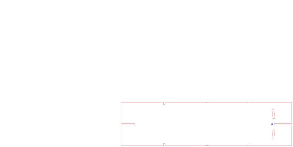
Press-Fit Cardboard Surfboard fish_510.panel_1.pdf 192 Kb
-
Vinyl Cut License Plate licenseplate.pdf 335 Kb
-
LaserGRBL
-
G-Code to Laser Cutter global_open_time_parametric-0.30_2x2_35pct.nc 4 Kb
-
CutStudio
-
Vinyl Cut Boat Number little_blue.cst 6 Kb