Electronics Design
This week I learned how to use test equipment and design electronics. This included:
Unit Description
Group assignment:
- Use the test equipment in your lab to observe the operation of a microcontroller circuit board (as a minimum, you should demonstrate the use of a multimeter and oscilloscope)
- Document your work on the group work page and reflect what you learned on your individual page
Individual assignment:
- Use an EDA tool to design a development board to interact and communicate with an embedded microcontroller
Learning outcomes
- Select and use software for circuit board design
- Demonstrate workflows used in circuit board design
Checklist
Linked to the group assignment page:
-
Linked to the group assignment page:
-
There are two types of assignments, one group and one individual, since I am alone in my personal Fab Lab I will do both. All of my work will be documented here, so there won’t be a group assignment page.
-
Use the test equipment in your lab to observe the operation of a microcontroller circuit board (as a minimum, you should demonstrate the use of a multimeter and oscilloscope)
-
Document your work and reflect on what you learned.
This is my electronics bench where I solder and use test equipment.
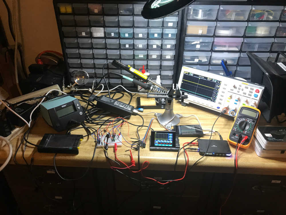
- Since my workbench is not near my computer, sometimes it is more convenient to move my test equipment next to my computer.
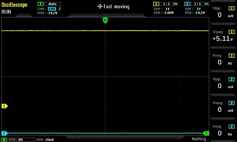
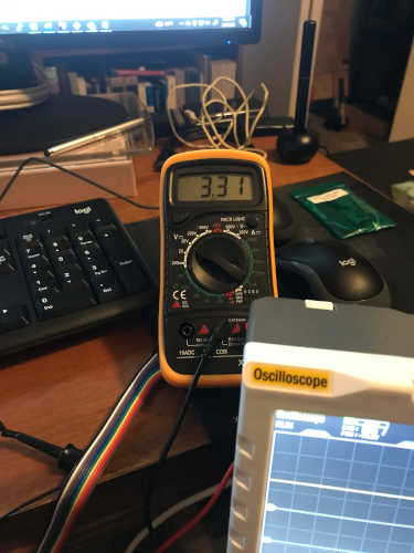
This is my multimeter and oscilloscope setup next to my computer so I can share the USB of the oscilloscope with the computer. I am measuring the 5V output voltage of the QuentTorres board.

This is the screenshot of the oscilloscope.
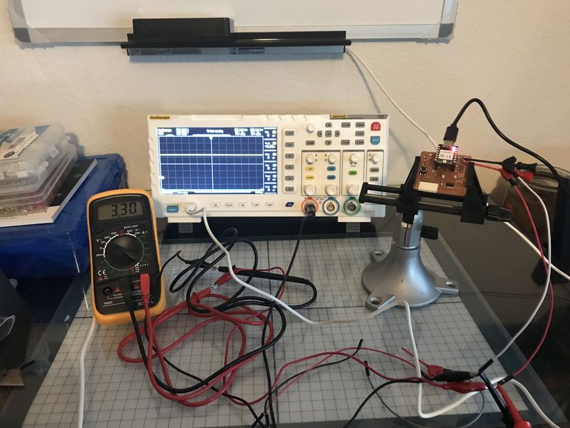
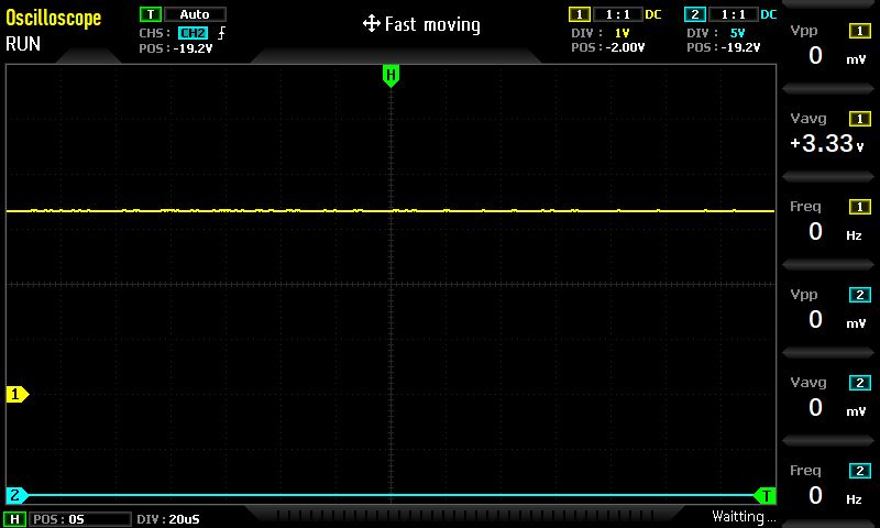
I am measuring the 3.3V output voltage of the QuentTorres board.
This is the screenshot of the oscilloscope.
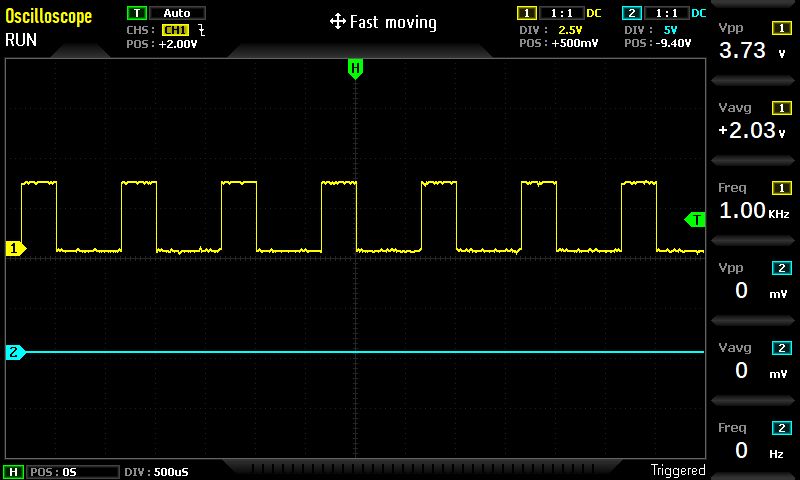
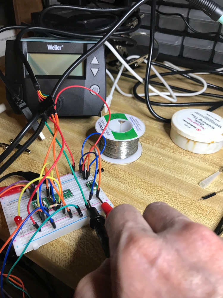
To demonstrate the multimeter with the oscilloscope I measured the SWD_LED on the QuenTorres board while running the program Fading.ino to see the PWM. This is the program from Examples>01.Basics>Fade
/*
  Fading

  This example shows how to fade an LED using the analogWrite() function.

  The circuit:
  - LED attached from digital pin 9 to ground through 220 ohm resistor.

  created 1 Nov 2008
  by David A. Mellis
  modified 30 Aug 2011
  by Tom Igoe
  modified 18 Mar 2024
  by Jim Hart

  This example code is in the public domain.

  https://www.arduino.cc/en/Tutorial/BuiltInExamples/Fading
*/

int ledPin = D7;  // SWD_LED connected to digital pin 7 on the XIAO. The Oscilloscope is connected to pin 7 of the Conn_PinHeader.

void setup() {
  // nothing happens in setup
}

void loop() {
  // fade in from min to max in increments of 5 points:
  for (int fadeValue = 0; fadeValue <= 255; fadeValue += 5) {
    // sets the value (range from 0 to 255):
    analogWrite(ledPin, fadeValue);
    // wait for 30 milliseconds to see the dimming effect
    delay(30);
  }

  // fade out from max to min in increments of 5 points:
  for (int fadeValue = 255; fadeValue >= 0; fadeValue -= 5) {
    // sets the value (range from 0 to 255):
    analogWrite(ledPin, fadeValue);
    // wait for 30 milliseconds to see the dimming effect
    delay(30);
  }
}
This is a video of the setup.
Here is a screenshot of the oscilloscope.
Explained problems and how you fixed them:
- Explained problems and how you fixed them:
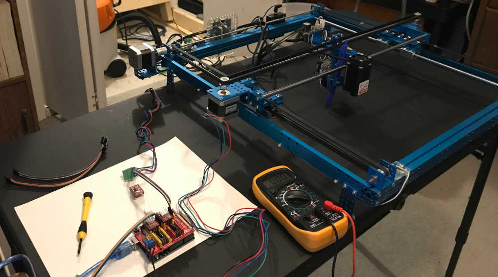
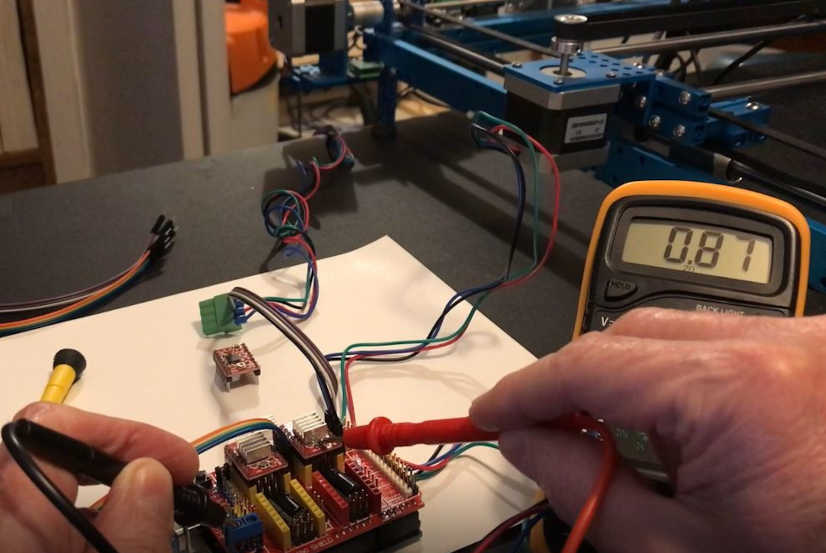
My first encounter with problem solving using test equipment during Fab Academy included using a multimeter to measure the voltage of a stepper motor driver during machine week in the 2022 Fab Academy Cycle. I had a problem with the first stepper motor driver; the x-axis stepper motor would not turn. I thought it may be the software, so I tried the ino code provided by Electronic Clinic, still no movement. I placed a different stepper motor driver in the socket and had success. I checked the Vref voltage and found it at 0.56 volts by using the negative power connection as a common and touched the potentiometer with the positive lead. I put the other stepper motor driver back in the socket, turned the potentiometer until the stepper motor responded, and then adjusted Vref to 0.87 volts. After properly adjusting the Vref, the stepper motors were very responsive. I tested the x-axis and y-axis movement successfully.
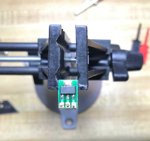
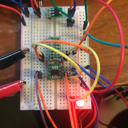
The next opportunity came up when I worked with the attiny412 last cycle. My goal was to use the attiny412 as the mcu for the remainder of my projects; this is due to it being the only mcu I could obtain for my personal Fab lab. : In the spirit of networking week, I wanted to prepare myself to use the t412 going forward. My goal is to communicate with my devices using this mcu in modules. @adrian.torres did amazing work to help me through this process; I stood on his shoulders to inspire me on my adventure. I started with a t412 mcu board; I had some protoboards just for this purpose. I soldered the t412 first and then added the connections to be able to plug the board into a prototyping board. Next, I thought I should make a power supply board, so I soldered an AMS1117-3.3volt regulator on a protoboard. I had some capacitors to use in the process. With the help of my friend at this YouTube link I was able to make the power supply unit I needed. To make a long story “short” :) I put too high of a voltage into the regulator and fried the first one. The NRF24L01+ modules were not working since they were fried as well. Documentation to come in networking week. Finally, I was able to program the t412 and load the hello.t412.blink using updi as the interface.
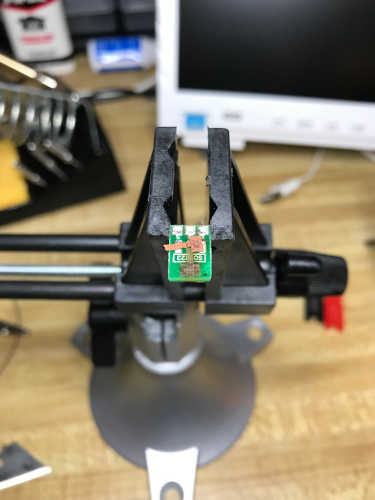
This is the regulator in question:
By the looks of the protoboard, I think it got too hot:
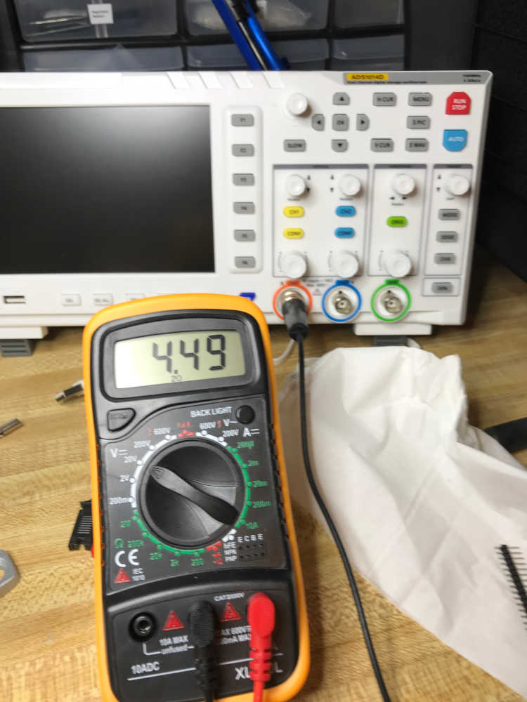
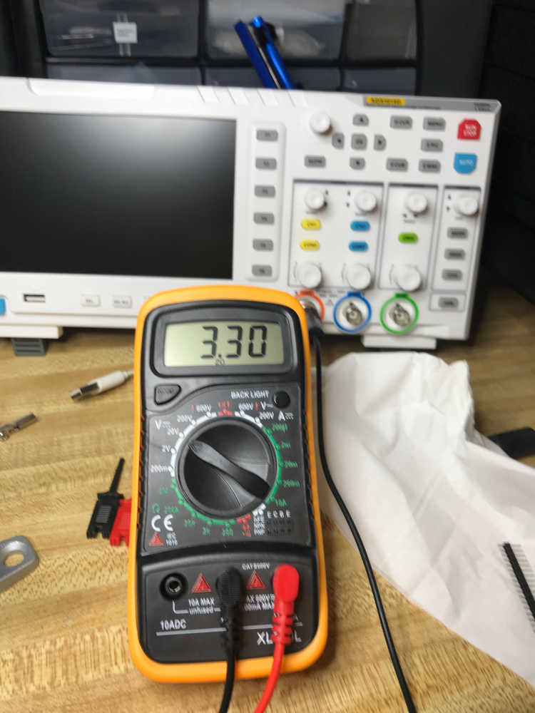
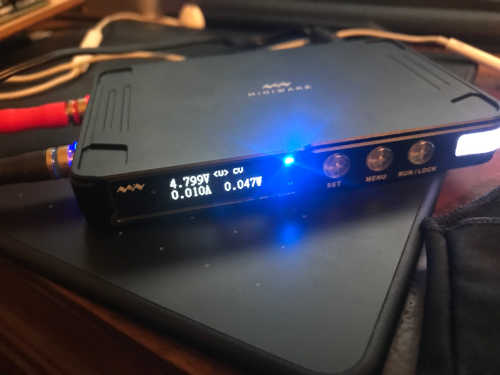
The output voltage of the regulator before repair:
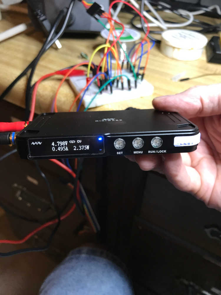
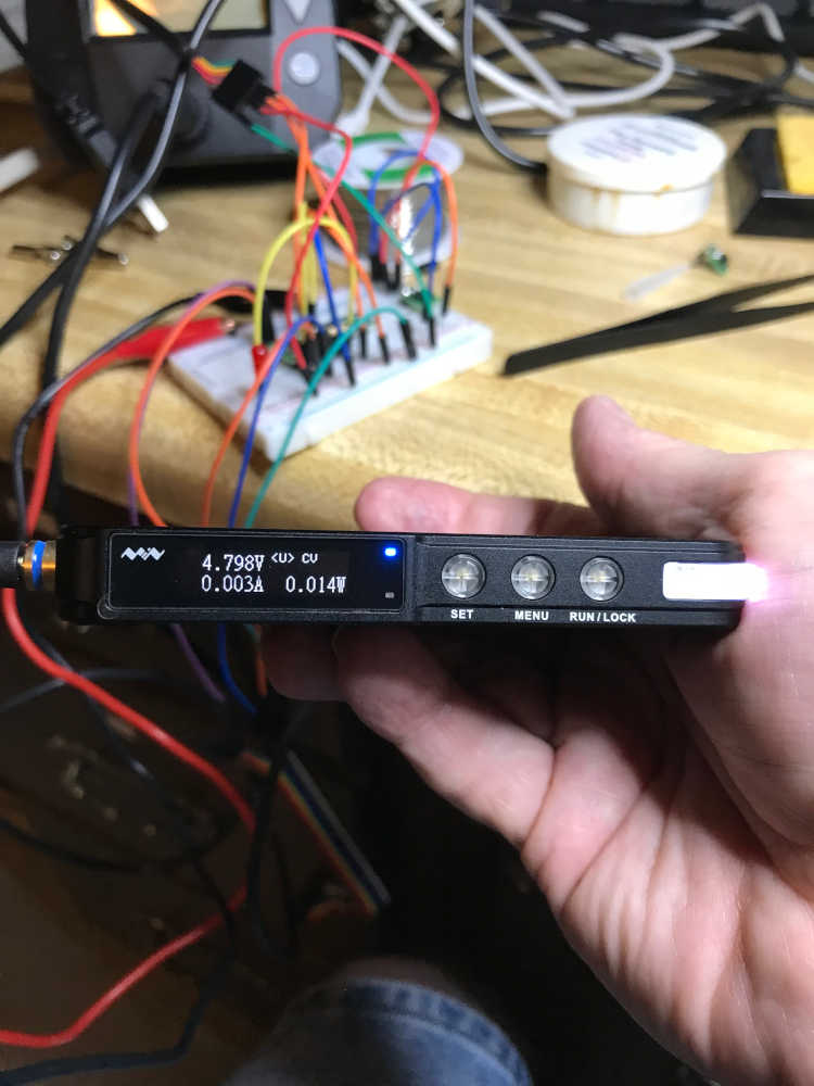
The voltage and current supplied to the regulator with no load:
After repairing the regulator, I went through the same steps to confirm it was operating properly.
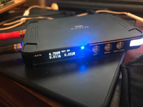
The output voltage of the regulator after repair:
The voltage and current supplied to the regulator with no load:
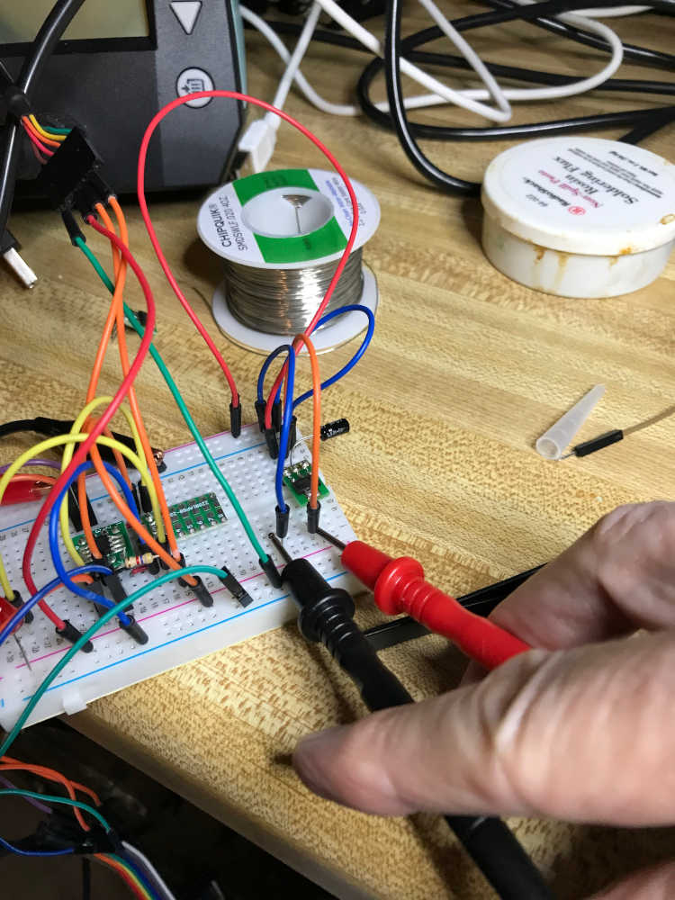
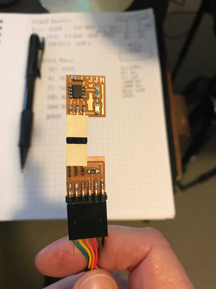
ATtiny412 development board in modules:
Test lead connections:
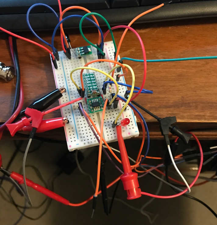
Supply voltage and current to the ATtiny412 (notice the current/power change when the LED blinks):
ATtiny412 voltage at VCC and GND:
This is a short clip showing the ATtiny412 blinking an LED as the oscilloscope measures the digital signal on PA2 (pin 5):
Research
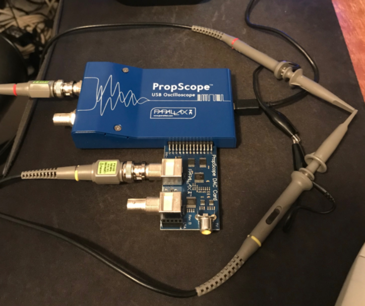
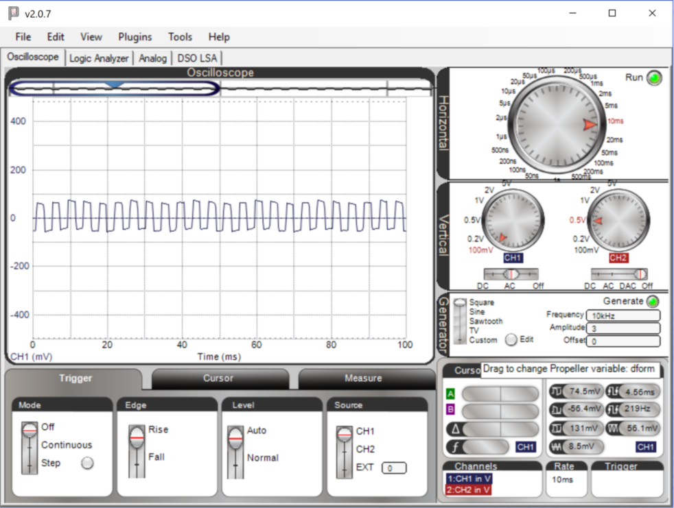
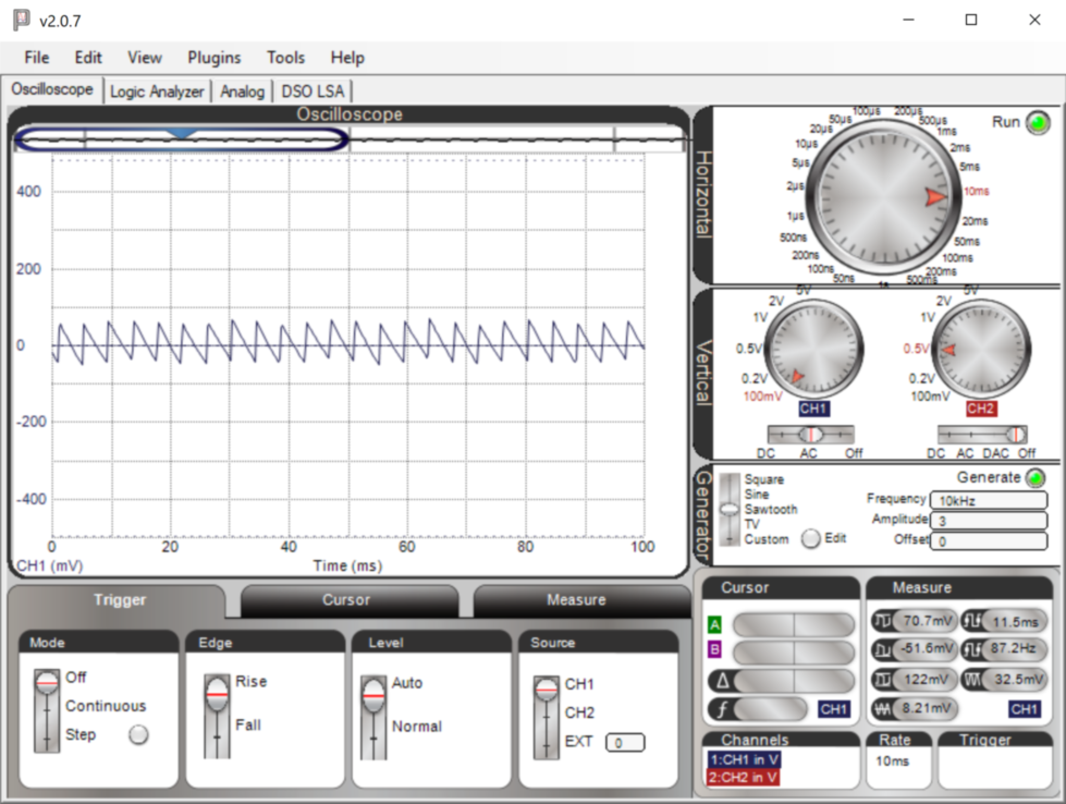
This research was conducted during the Fab Academy 2019 cycle. Although it did not accomplish the goals of the assignment, it was interesting to see this device display like an oscilloscope on my computer screen.
- Installed and tested USB Oscilloscope - Parallax Propscope 25MHz

Documented what you have learned in electronics design:
- Documented what you have learned in electronics design:
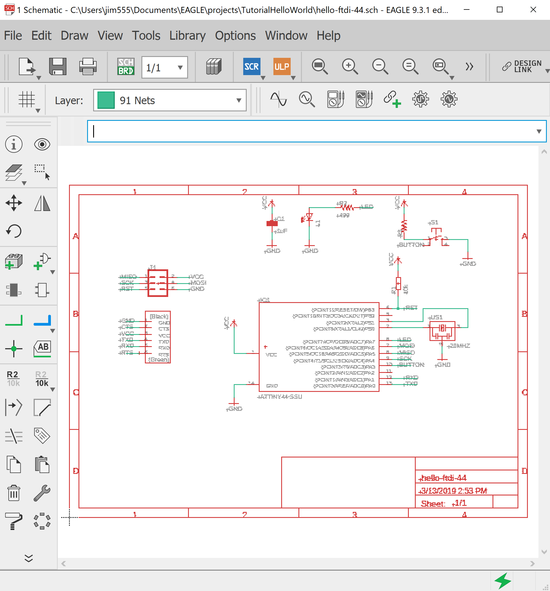
When I visited LCCC, I had been dabbling in Eagle, but I really wanted to learn to use the python code that Neil showed us. Paul and Bridgette helped, but I just didn’t like the interface. Eagle was nice for stuffing the board, but the trace placement was a little frustrating. I couldn’t put the traces exactly where I wanted to and was at the mercy of the “program”. This was in the “Make Something Big” week and I was already behind. I really needed to get things going to get caught up.
- Installed Eagle PCB design software and designed echo hello-world guided through the tutorial.
Included original design files (Eagle, KiCad, etc.):
- Included original design files (Eagle, KiCad, etc.):
Design Files Eagle
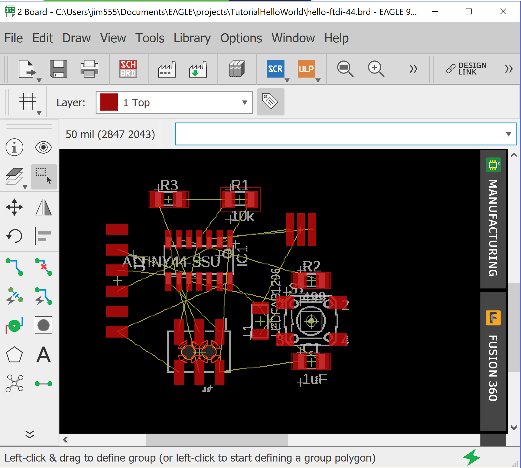
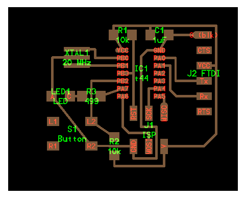
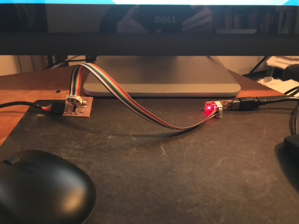
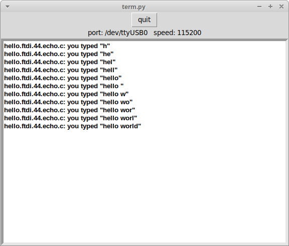
When I got back home, I really immersed myself into the python and got “outside”. I followed a video demonstration of pcb.py that used the hello.ftdi.44 board during the Fab Academy 2019 cycle, but during the Fab Academy 2023 cycle I could only find Neil’s video showing step-by-step how to understand how code could turn into a graphic representation of a board. I used the board image and the hello.ftdi.44.py to get the hang of it. Once I got the switch and LED figured out, I needed to learn how to program the board. I wasn’t even sure if my FabTinyISP would be able to program my Hello World board. Thankfully, I did manage to program and Putty into the Hello World board and make it talk to me 🙂
- Used pcb.py|frep.py 250 after completing Eagle design. It is difficult to describe the process, but I essentially retyped Neil’s code in the “define board” block of code and watched the board come to life as I typed. I made the modifications necessary (shown below) to include a button (S1) and LED (LED1) as shown in the tutorial. I also found some help from an archive from 2017 to help me understand the wiring. Thank you Fab Lab nerve centre and Fab Lab Leon!!
Code Example
#
# define board. Used Neil's example as a guide, but stuffed every part and
#               made the traces "by hand"
#

w = .015
width = 1.5
height = 1.2
mask = .004
x = 1
y = 1
z = -.005
d = .06

pcb = PCB(x,y,width,height,mask)

IC1 = ATtiny44_SOICN('IC1\nt44')
pcb = IC1.add(pcb,x+.87,y+.77,z)

J1 = header_ISP('J1\nISP')
pcb = J1.add(pcb,IC1.x+.05,IC1.pad[7].y-.22,z,angle=90)

pcb = wire(pcb,w,
   IC1.pad[8],
   point(J1.pad[1].x,IC1.pad[8].y,z),
   J1.pad[1])

pcb = wire(pcb,w,
   IC1.pad[9],
   point(J1.pad[3].x,IC1.pad[9].y,z),
   J1.pad[3])

pcb = wire(pcb,w,
   IC1.pad[7],
   point(IC1.pad[7].x,J1.y+.02,z),
   point(IC1.pad[7].x+.04,J1.y-.02,z),
   point(J1.pad[4].x,J1.y-.02,z),
   J1.pad[4])

pcb = wire(pcb,w,
   IC1.pad[4],
   point(J1.pad[5].x,IC1.pad[4].y,z),
   J1.pad[5])

pcb = wire(pcb,w,
   IC1.pad[14],
   point(J1.x-.01,IC1.pad[14].y,z),
   point(J1.x-.05,IC1.pad[14].y-.04,z),
   point(J1.x-.05,J1.y+.02,z),
   point(J1.x+.05,J1.y+.02,z),
   point(J1.x+.05,J1.pad[2].y-.08,z),
   point(J1.pad[6].x,J1.pad[2].y-.08,z),
   J1.pad[6])

J2 = header_FTDI('J2 FTDI')
pcb = J2.add(pcb,x+width-.22,IC1.y-.0,z,angle=0)

pcb = wire(pcb,w,
   J1.pad[2],
   point(J2.x,J1.pad[2].y,z),
   point(J2.x+.08,J1.pad[2].y+.08,z),
   point(J2.x+.08,J2.pad[3].y,z),
   J2.pad[3])

pcb = wire(pcb,w,
   IC1.pad[13],
   point(IC1.pad[13].x+.105,IC1.pad[13].y,z),
   point(IC1.pad[13].x+.105,J2.pad[4].y,z),
   J2.pad[4])

pcb = wire(pcb,w,
   IC1.pad[12],
   point(IC1.pad[12].x+.07,IC1.pad[12].y,z),
   point(IC1.pad[12].x+.07,J2.pad[5].y+.04,z),
   point(IC1.pad[12].x+.11,J2.pad[5].y,z),
   J2.pad[5])

XTAL1 = XTAL_EFOBM('XTAL1\n20 MHz')
pcb = XTAL1.add(pcb,IC1.pad[4].x-.3,IC1.pad[13].y+.003,z,angle=-90)

pcb = wire(pcb,w,
   IC1.pad[2],
   point(XTAL1.x+.12,IC1.pad[2].y,z),
   point(XTAL1.x+.12,XTAL1.pad[1].y,z),
   XTAL1.pad[1])

#pcb = wire(pcb,w,
#   J1.pad[6],
#   point(J1.pad[6].x,J1.pad[6].y-.08,z),
#   point(XTAL1.x-.04,J1.pad[6].y-.08,z),
#   point(XTAL1.x-.12,J1.pad[6].y,z),
#   point(XTAL1.x-.12,XTAL1.pad[2].y,z),
#   XTAL1.pad[2])

pcb = wire(pcb,w,
   IC1.pad[3],
   XTAL1.pad[3])


R1 = R_1206('R1\n10k');
pcb = R1.add(pcb,IC1.pad[1].x,IC1.pad[1].y+.1,z)

pcb = wire(pcb,w,
   R1.pad[1],
   IC1.pad[1])

pcb = wire(pcb,w,
   J2.pad[3],
   point(J2.pad[3].x+.08,J2.pad[3].y,z),
   point(J2.pad[3].x+.08,R1.y+.06,z),
   point(R1.pad[1].x,R1.y+.06,z),
   R1.pad[1])

pcb = wire(pcb,w,
   R1.pad[2],
   point(J1.pad[5].x,R1.y,z),
   J1.pad[5])

C1 = C_1206('C1\n1uF');
pcb = C1.add(pcb,IC1.pad[14].x,R1.y,z)

pcb = wire(pcb,w,
   IC1.pad[14],
   C1.pad[2])

pcb = wire(pcb,w,
   C1.pad[1],
   point(C1.pad[1].x,C1.y+.06,z))

pcb = wire(pcb,w,
   J2.pad[1],
   C1.pad[2])

S1 = button_6mm('S1\nButton');
pcb = S1.add(pcb,J1.pad[5].x-.4,IC1.pad[7].y-.245,z)

pcb = wire(pcb,w,
   IC1.pad[5],
   point(S1.x+.125,IC1.pad[5].y,z),
   S1.pad[4])

pcb = wire(pcb,w,
   S1.pad[3],
   J1.pad[6])

R2 = R_1206('R2\n10k');
pcb = R2.add(pcb,S1.pad[2].x+.4,J1.pad[4].y,z,angle=-90)

pcb = wire(pcb,w,
   R2.pad[1],
   S1.pad[4])

pcb = wire(pcb,w,
   R2.pad[2],
   point(R2.pad[2].x,R2.pad[2].y-.07,z),
   point(J1.pad[2].x,J1.pad[2].y-.13,z),
   J1.pad[2])

#J2.pad[3],
#   point(J2.pad[3].x+.08,J2.pad[3].y,z),
#   point(J2.pad[3].x+.08,R1.y+.06,z),
#   point(R1.pad[1].x,R1.y+.06,z),
#   R1.pad[1])

LED1 = LED_1206('LED1\nLED')
pcb = LED1.add(pcb,S1.pad[1].x+.05,IC1.pad[7].y,z)

pcb = wire(pcb,w,
   LED1.pad[1],
   point(LED1.x-.055,XTAL1.pad[2].y,z),
   XTAL1.pad[2])

pcb = wire(pcb,w,
   S1.pad[3],
   LED1.pad[1])

R3 = R_1206('R3\n499');
pcb = R3.add(pcb,S1.pad[3].x,IC1.pad[7].y,z)

pcb = wire(pcb,w,
   R3.pad[2],
   IC1.pad[6])

pcb = wire(pcb,w,
   LED1.pad[2],
   R3.pad[1])
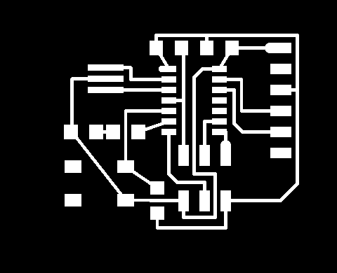
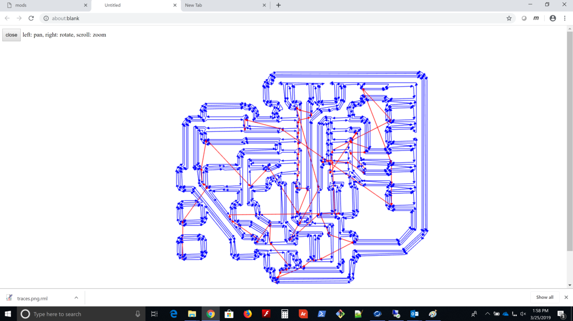
- Used pcb.py and frep.py to “Design It” and generate these images to bring into mods
- “Make It”
Included a ‘hero shot’:
-
Included a ‘hero shot’:
-
“Stuff It”
- “Program It”
Make the hex code to be flashed
jimhart@jimhart-Xubuntu2:~/avr$ make -f hello.ftdi.44.echo.interrupt.c.make
avr-gcc -mmcu=attiny44 -Wall -Os -DF_CPU=20000000 -I./ -o hello.ftdi.44.echo.interrupt.out hello.ftdi.44.echo.interrupt.c
avr-objcopy -O ihex hello.ftdi.44.echo.interrupt.out hello.ftdi.44.echo.interrupt.c.hex;\
avr-size --mcu=attiny44 --format=avr hello.ftdi.44.echo.interrupt.out
AVR Memory Usage
----------------
Device: attiny44

Program:     830 bytes (20.3% Full)
(.text + .data + .bootloader)

Data:         74 bytes (28.9% Full)
(.data + .bss + .noinit)
Flash to board through ftdi using avrdude
jimhart@jimhart-Xubuntu2:~/avr$ avrdude -c usbtiny -p attiny44 -U flash:w:hello.ftdi.44.echo.interrupt.c.hex

avrdude: AVR device initialized and ready to accept instructions

Reading | ################################################## | 100% 0.00s

avrdude: Device signature = 0x1e9207 (probably t44)
avrdude: NOTE: "flash" memory has been specified, an erase cycle will be performed
         To disable this feature, specify the -D option.
avrdude: erasing chip
avrdude: reading input file "hello.ftdi.44.echo.interrupt.c.hex"
avrdude: input file hello.ftdi.44.echo.interrupt.c.hex auto detected as Intel Hex
avrdude: writing flash (830 bytes):

Writing | ################################################## | 100% 1.27s

avrdude: 830 bytes of flash written
avrdude: verifying flash memory against hello.ftdi.44.echo.interrupt.c.hex:
avrdude: load data flash data from input file hello.ftdi.44.echo.interrupt.c.hex:
avrdude: input file hello.ftdi.44.echo.interrupt.c.hex auto detected as Intel Hex
avrdude: input file hello.ftdi.44.echo.interrupt.c.hex contains 830 bytes
avrdude: reading on-chip flash data:

Reading | ################################################## | 100% 1.66s

avrdude: verifying ...
avrdude: 830 bytes of flash verified

avrdude: safemode: Fuses OK (E:FF, H:DF, L:5E)

avrdude done.  Thank you.
- “Test It”
This is a continuation of the Electronics Design week in Fab Academy 2023
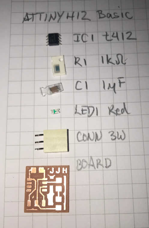
Since I intend to use a Tiny412 microcontroller for my final project, I will design a basic board using this mcu to blink a LED. I made this board during Output Devices, but discovered that it was insufficient for the assignment and designed another board to output to an OLED. So here we go!
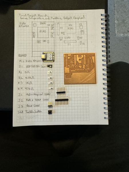
I decided to start at the beginning; just make the schematic and board for a basic attiny412 blinking the LED, so that’s what I set out to do. I looked at Neil’s hello.t412.3.blink.png and listed the components in my note book. Actually, I did that later, but this is probably the correct way to do it:
Checked your board can be fabricated:
- Checked your board can be fabricated:
So how did I make that board! :) I’ll tell the story:
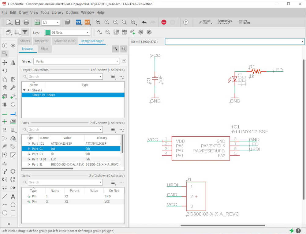
- With the list of parts, I went into Eagle made a new project and made sure the libraries were there. After making a new Schematic, I used ADD to add the parts in the Schematic Editor. Using Net, I added wires to each of the connections and used Name to interconnect all of the connections. After a lot of practice, it was a breeze. Once the schematic is done, you should use ERC under Tools to check for electrical errors: Tools > ERC and look for anny errors or omissions. I had to add the values of the capacitor and resistor. Very helpful! Here is the result:
- I used the autoroute after I arranged the components in the same position Neil had them and the results weren’t too bad, but I did delete spme routes and fixed them. I also ran DRC under Tools > DRC to check the Design Rules found in fab.dru. It actually turned out nicely:
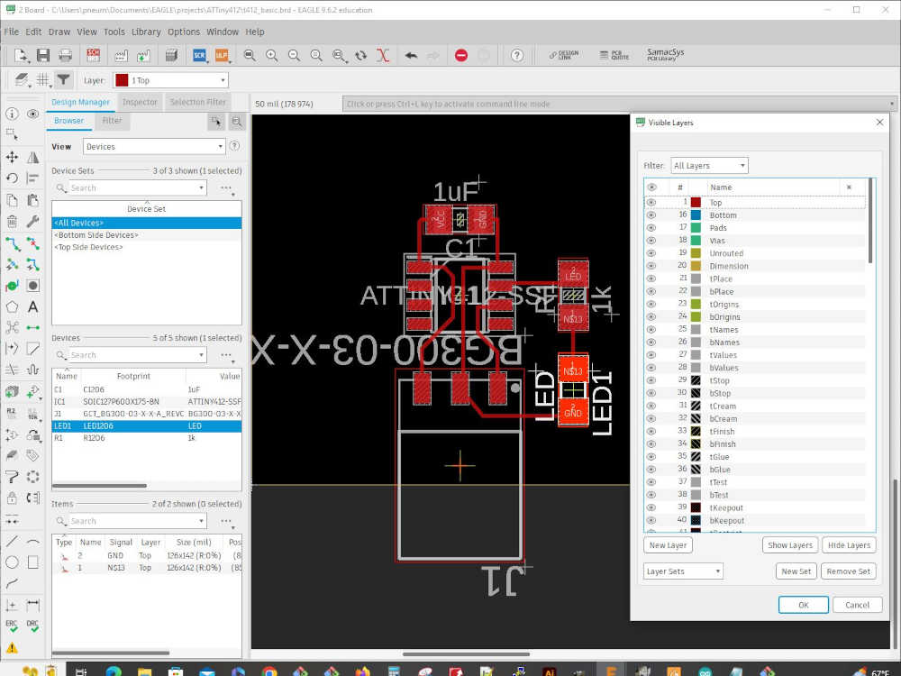
- This is the top layer after I finished the design:
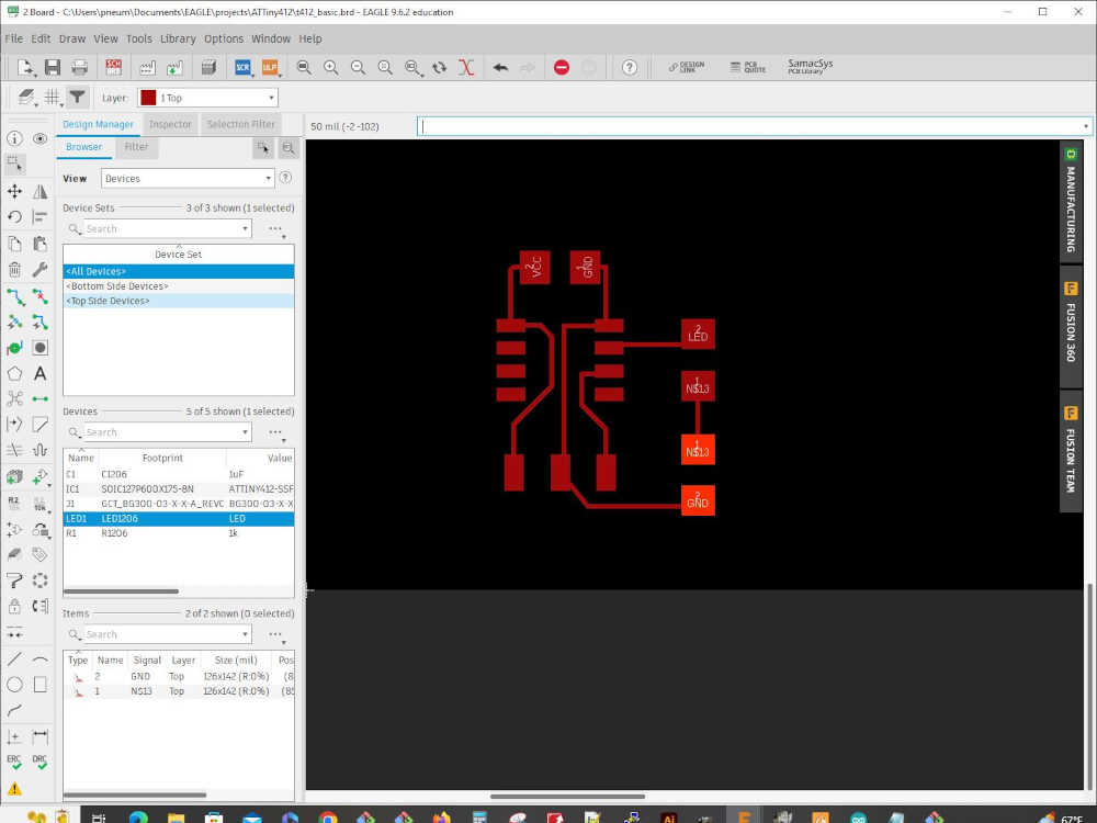
- The next step is to File > Export > Image > give the file a name > Check Monochrome > Set Resolution to 1000 > Set Area to Full. This is what I received:

- With the output in GIMP, I cropped it to the size I thought would work as a board (similar to Neil’s example) > Changed the canvas size and added 40 pixels (make sure Width and Height are linked) > Press the Tab key > Click Center > Resize All Layers > Fill with White > Click Resize > Export as a png file. This is the result (you can’t see the white border, but it has one):

- The next part was tricky and I can’t remember exactly how I got it to work, but basically, I made the center white and the border black. I’ll try again later and document it here. As promised: After you crop the output, it is better to Select All > Copy > File > New (this opens a new file with the dimensions of the copied image with a white background) > Don’t Paste the image > Just Change the canvas size as mentioned above, but fill the border with the foreground color instead of White (Make sure you center. Voila! You have a black frame around the white center. This is what you need for the png to bring into mods:

-
I used mods and brought the png files in and save the g-code as I did here
-
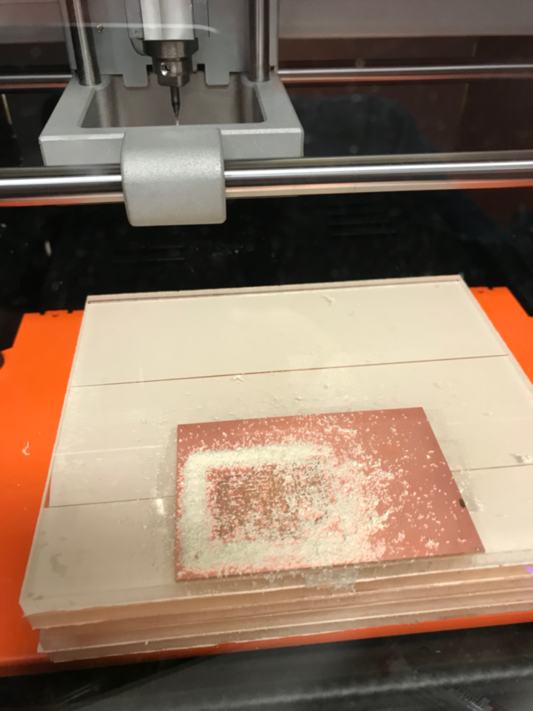
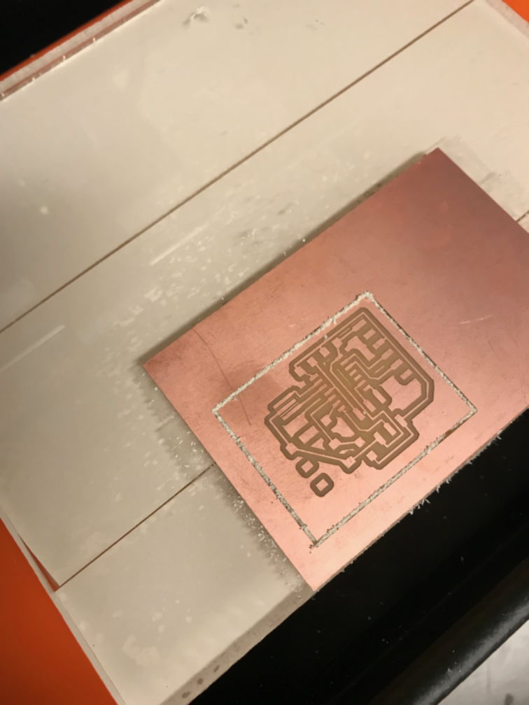
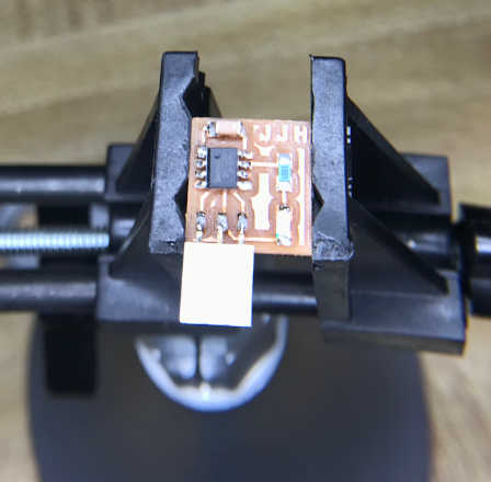
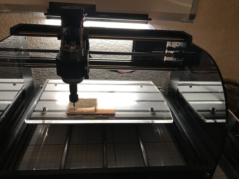
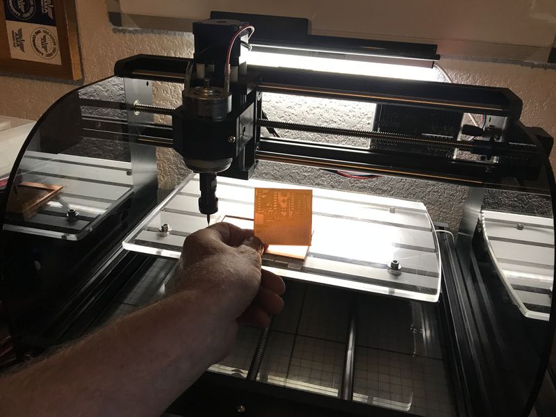
I milled the board very easily after so much practice with the serial-updi interface board :)
-
The board was stuffed:
- The first attempt to program the board failed because I had the serial-updi interface reversed:
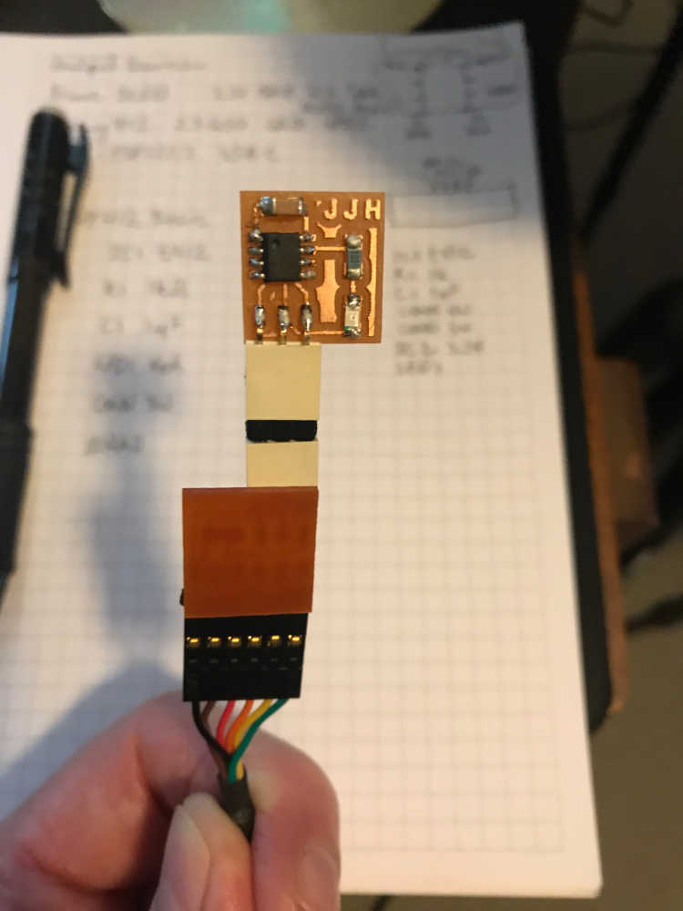
- The second attempt was successful using Neil’s blink.ino from embedded programming:
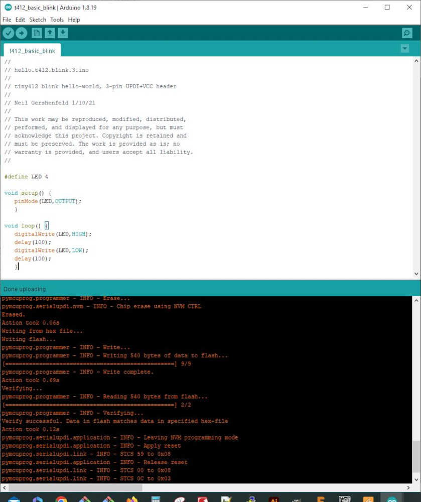
Sketch uses 540 bytes (13%) of program storage space. Maximum is 4096 bytes.
Global variables use 10 bytes (3%) of dynamic memory, leaving 246 bytes for local variables. Maximum is 256 bytes.
C:\Users\pneum\AppData\Local\Arduino15\packages\megaTinyCore\tools\python3\3.7.2-post1/python3 -u C:\Users\pneum\AppData\Local\Arduino15\packages\megaTinyCore\hardware\megaavr\2.5.11/tools/prog.py -t uart -u COM11 -b 230400 -d attiny412 --fuses 2:0x02 6:0x04 8:0x00 -fC:\Users\pneum\AppData\Local\Temp\arduino_build_20051/t412_basic_blink.ino.hex -a write -v
SerialUPDI
UPDI programming for Arduino using a serial adapter
Based on pymcuprog, with significant modifications
By Quentin Bolsee and Spence Konde
Version 1.2.3 - Jan 2022
Using serial port COM11 at 230400 baud.
Target: attiny412
Set fuses: ['2:0x02', '6:0x04', '8:0x00']
Action: write
File: C:\Users\pneum\AppData\Local\Temp\arduino_build_20051/t412_basic_blink.ino.hex
pymcuprog.programmer - INFO - Setting up programming session for 'attiny412'
pymcuprog.deviceinfo.deviceinfo - INFO - Looking for device attiny412
pymcuprog.serialupdi.physical - INFO - Opening port 'COM11' at '115200' baud
pymcuprog.serialupdi.link - INFO - STCS 08 to 0x03
pymcuprog.serialupdi.link - INFO - STCS 06 to 0x02
pymcuprog.serialupdi.link - INFO - LDCS from 0x00
pymcuprog.serialupdi.link - INFO - UPDI init OK
pymcuprog.serialupdi.link - INFO - STCS 06 to 0x02
pymcuprog.serialupdi.link - INFO - Setting UPDI clock to 8 MHz
pymcuprog.serialupdi.link - INFO - STCS 02 to 0x09
pymcuprog.serialupdi.physical - INFO - Switching to '230400' baud
pymcuprog.serialupdi.application - INFO - SIB: 'tinyAVR P:0D:0-3M2 (02.59B14.0)'
pymcuprog.serialupdi.application - INFO - Device family ID: 'tinyAVR'
pymcuprog.serialupdi.application - INFO - NVM interface: 'P:0'
pymcuprog.serialupdi.application - INFO - Debug interface: 'D:0'
pymcuprog.serialupdi.application - INFO - PDI oscillator: '3M2'
pymcuprog.serialupdi.application - INFO - Extra info: '(02.59B14.0)'
pymcuprog.serialupdi.application - INFO - Using 16-bit UPDI
pymcuprog.serialupdi.link - INFO - LDCS from 0x00
pymcuprog.serialupdi.application - INFO - PDI revision = 0x02
pymcuprog.serialupdi.link - INFO - LDCS from 0x0B
pymcuprog.serialupdi.link - INFO - LDCS from 0x0B
pymcuprog.serialupdi.application - INFO - Entering NVM programming mode
pymcuprog.serialupdi.link - INFO - LDCS from 0x07
pymcuprog.serialupdi.application - INFO - Apply reset
pymcuprog.serialupdi.link - INFO - STCS 59 to 0x08
pymcuprog.serialupdi.application - INFO - Release reset
pymcuprog.serialupdi.link - INFO - STCS 00 to 0x08
pymcuprog.serialupdi.link - INFO - LDCS from 0x0B
pymcuprog.serialupdi.link - INFO - LDCS from 0x0B
pymcuprog.serialupdi.link - INFO - LDCS from 0x0B
pymcuprog.serialupdi.link - INFO - LDCS from 0x0B
pymcuprog.serialupdi.link - INFO - LDCS from 0x0B
pymcuprog.nvm - INFO - No specific initializer for this provider
Pinging device...
pymcuprog.programmer - INFO - Reading device ID...
pymcuprog.serialupdi.application - INFO - SIB: 'tinyAVR P:0D:0-3M2 (02.59B14.0)'
pymcuprog.serialupdi.application - INFO - Device family ID: 'tinyAVR'
pymcuprog.serialupdi.application - INFO - NVM interface: 'P:0'
pymcuprog.serialupdi.application - INFO - Debug interface: 'D:0'
pymcuprog.serialupdi.application - INFO - PDI oscillator: '3M2'
pymcuprog.serialupdi.application - INFO - Extra info: '(02.59B14.0)'
pymcuprog.serialupdi.application - INFO - Using 16-bit UPDI
pymcuprog.serialupdi.link - INFO - LDCS from 0x00
pymcuprog.serialupdi.application - INFO - PDI revision = 0x02
pymcuprog.serialupdi.link - INFO - LDCS from 0x0B
pymcuprog.serialupdi.application - INFO - Device ID from pyupdi = '1E9223' rev 'C'
pymcuprog.nvm - INFO - Device ID: '1E9223'
pymcuprog.nvm - INFO - Device revision: 'C'
pymcuprog.nvm - INFO - Device serial number: 'b'304b444549304eb70231''
Ping response: 1E9223
Setting fuse 0x2=0x2
Writing literal values...
pymcuprog.programmer - INFO - Write...
pymcuprog.programmer - INFO - Writing 1 bytes of data to fuses...
pymcuprog.programmer - INFO - Write complete.
Verifying literal values...
pymcuprog.programmer - INFO - Reading 1 bytes from fuses...
pymcuprog.programmer - INFO - Verifying...
Action took 0.19s
Setting fuse 0x6=0x4
Writing literal values...
pymcuprog.programmer - INFO - Write...
pymcuprog.programmer - INFO - Writing 1 bytes of data to fuses...
pymcuprog.programmer - INFO - Write complete.
Verifying literal values...
pymcuprog.programmer - INFO - Reading 1 bytes from fuses...
pymcuprog.programmer - INFO - Verifying...
Action took 0.19s
Setting fuse 0x8=0x0
Writing literal values...
pymcuprog.programmer - INFO - Write...
pymcuprog.programmer - INFO - Writing 1 bytes of data to fuses...
pymcuprog.programmer - INFO - Write complete.
Verifying literal values...
pymcuprog.programmer - INFO - Reading 1 bytes from fuses...
pymcuprog.programmer - INFO - Verifying...
Action took 0.19s
Finished writing fuses.
Chip/Bulk erase,
Memory type eeprom is conditionally erased (depending upon EESAVE fuse setting)
Memory type flash is always erased
Memory type lockbits is always erased
...
pymcuprog.programmer - INFO - Erase...
pymcuprog.serialupdi.nvm - INFO - Chip erase using NVM CTRL
Erased.
Action took 0.06s
Writing from hex file...
Writing flash...
pymcuprog.programmer - INFO - Write...
pymcuprog.programmer - INFO - Writing 540 bytes of data to flash...
[==================================================] 9/9
pymcuprog.programmer - INFO - Write complete.
Action took 0.69s
Verifying...
pymcuprog.programmer - INFO - Reading 540 bytes from flash...
[==================================================] 2/2
pymcuprog.programmer - INFO - Verifying...
Verify successful. Data in flash matches data in specified hex-file
Action took 0.12s
pymcuprog.serialupdi.application - INFO - Leaving NVM programming mode
pymcuprog.serialupdi.application - INFO - Apply reset
pymcuprog.serialupdi.link - INFO - STCS 59 to 0x08
pymcuprog.serialupdi.application - INFO - Release reset
pymcuprog.serialupdi.link - INFO - STCS 00 to 0x08
pymcuprog.serialupdi.link - INFO - STCS 0C to 0x03
pymcuprog.serialupdi.physical - INFO - Closing port 'COM11'
Included a ‘hero shot’:
- Included a ‘hero shot’:
This is a continuation of the Electronics Design week in Fab Academy 2024
Prototyping for the Final Project
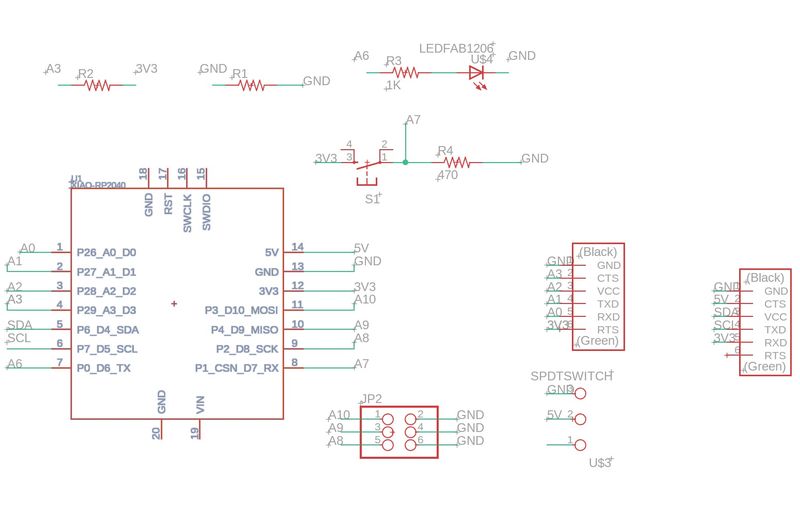
For Electronics Design I will need to make a board to host the microcontroller and receive the inputs as well as send the outputs. I propose to use the Fab-XIAO with a minor FABCAT Hack that consists of a pull-up resistor for the temperature sensor. Adrian, thank you for your excellent guidance and inspiration!
This is a minor addition to so great a work:
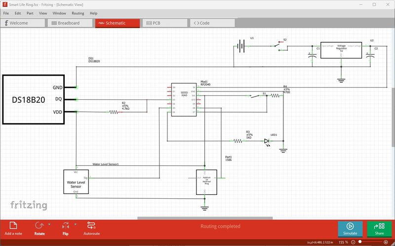
This is a Fritzing schematic of the Smart Life Ring electronic system. The voltage regulator will be on a separate power module board and will be supplied by a 7.4V 1500mAH Li-Po battery.
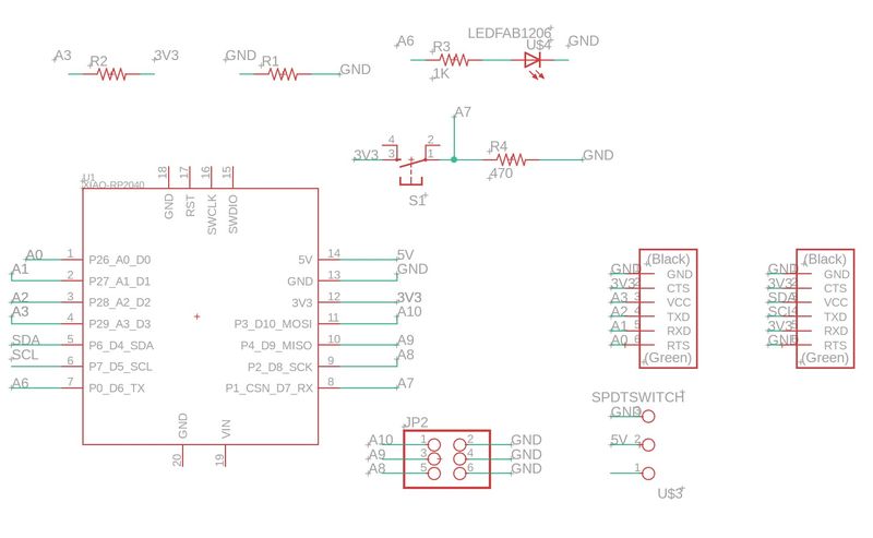
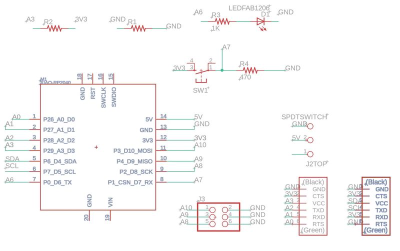
After discussing this with my Instructor, Adrian wanted me to show the schematic from Fusion 360 and I provided this schematic.
Adrian recommended that I add two more connectors and I explained that I intended to connect the battery power through a voltage regulator and connect to the 5v and GND pins and showed him this image.
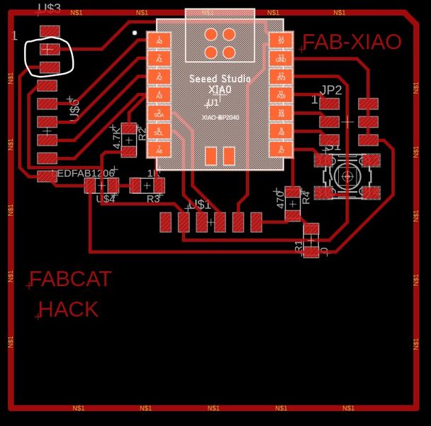
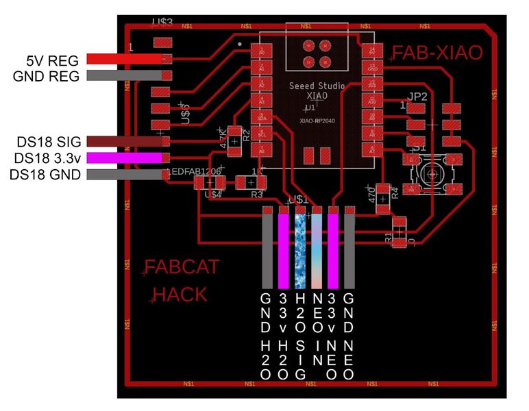
Adrian wisely insisted that I show how I will connect all of my components, so I designed a Photoshop image that included all of my connections.
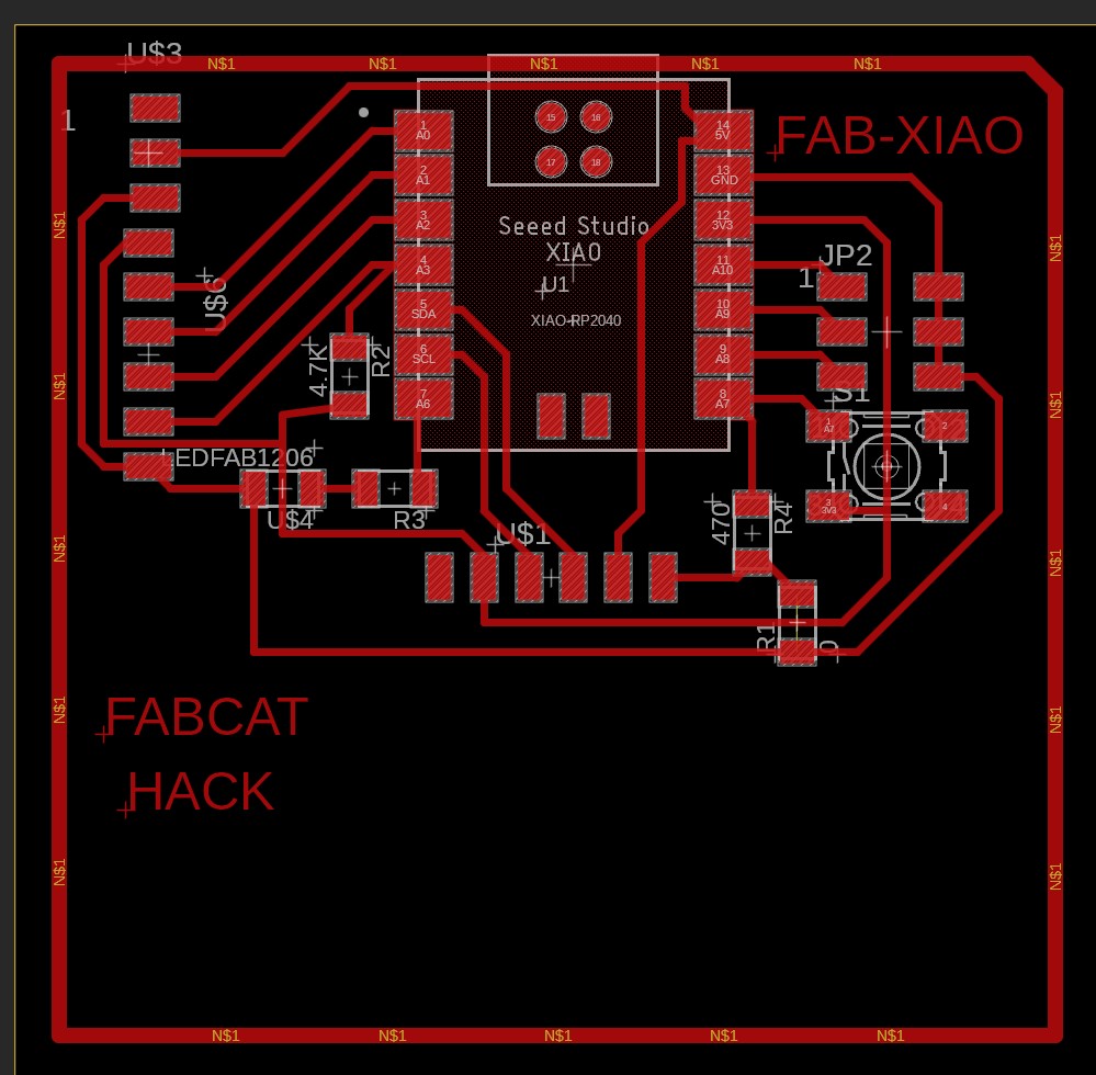
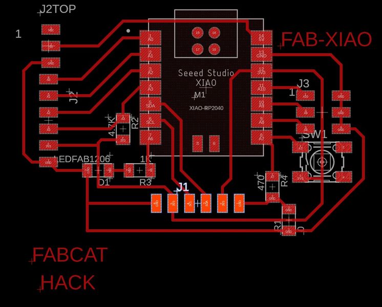
This was a valuable learning experience. I discovered that I did not have enough 3.3v connections to connect all of my components and I needed to reroute my wires in Fusion 360 that gave me even more experience toward Electronics Design. So I rerouted to “Try to arrange the systems all together (make GND, VCC and Signal packets). System Integration.” as my Instructor said. Here is the Fusion 360 board.
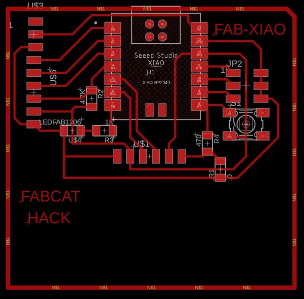
And this is the Fusion 360 schematic with all of the connections properly assigned.
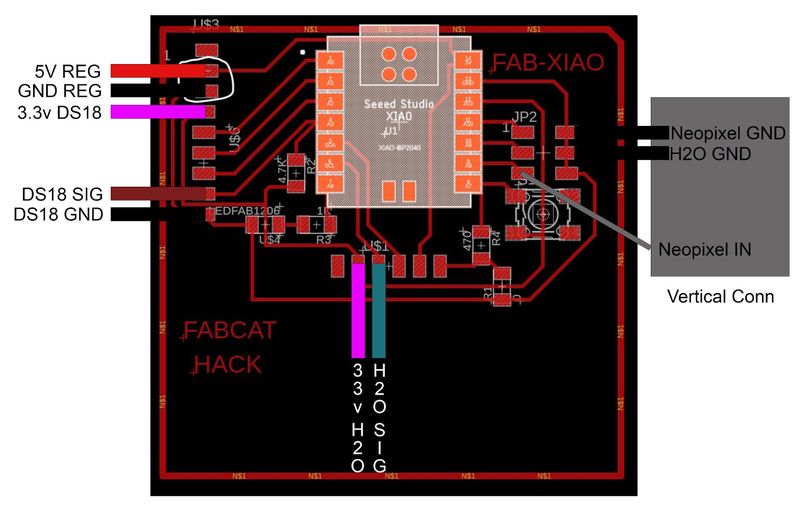
This is the Photoshop image with the connections labeled.
It is wonderful to have a patient Instructor :) With that sent for review, my Instructor said, “Perfect Jim. If you tried the neopixels with 3.3V and they work perfectly. Forward; It’s time to make the board.” Thank you Adrian!
I wish I could say that I just sent it to the milling machine and finished, but that is not what happened. I still need to take it a few more steps with the bits before I change the atoms. After crashing my 1/64” endmill while zeroing the Z axis, it was a long night and I had to save this for the next day after Global Open Time. I received help and guidance from my Instructor for the next steps and I will record the steps here.
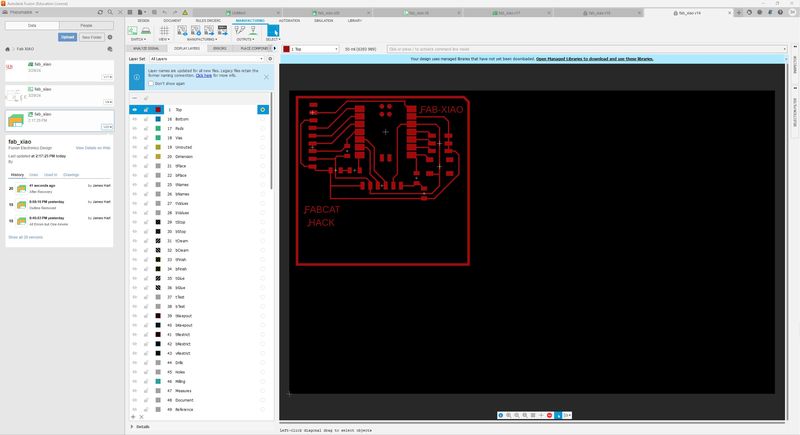
First, I had to learn a new workflow and realize that I couldn’t figure out how to export the monochrome image from Fusion 360 directly. I figured out another way ;) Turn off all layers except for the TOP.
Then use File > Export > Select Type as EAGLE 9.X brd compatible Files (*.brd) and export to an appropriate folder.
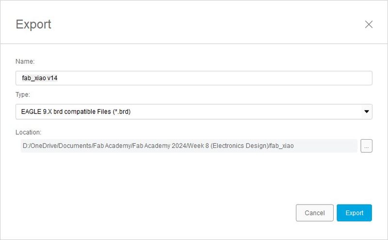
Next, open the .brd file in Eagle 9.X; I have 9.6.2.
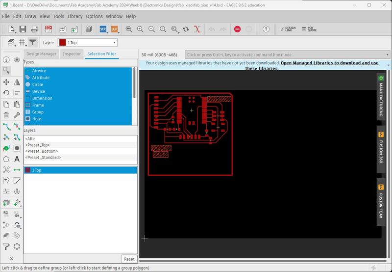
This is familiar territory now. Just follow the workflow from Electronics Design
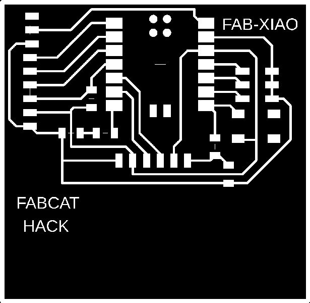
This is the traces image I obtained from GIMP.
This is the border file I obtained from GIMP.

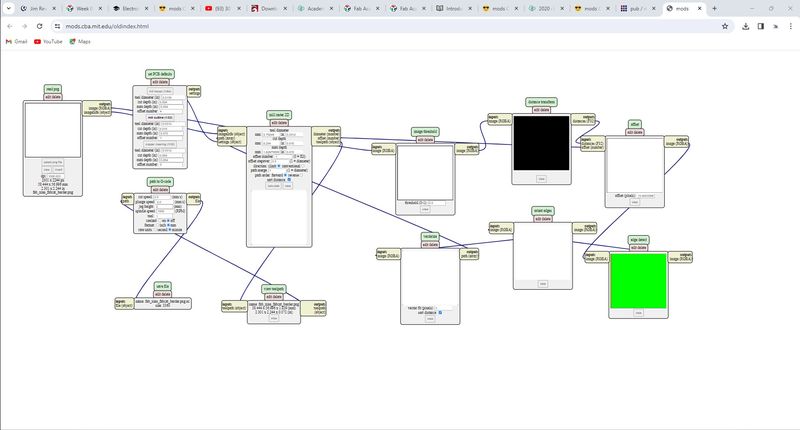
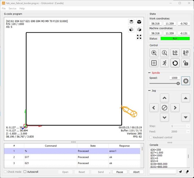
Using the old mods, because I am more familiar with it, I generated the gcode for the traces.
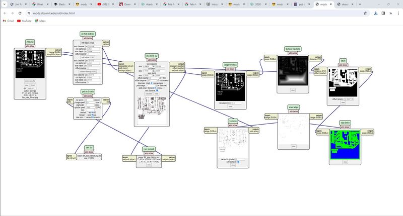
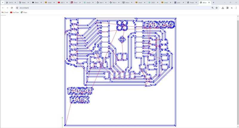
This is the output.
And the borders.
This is the output.

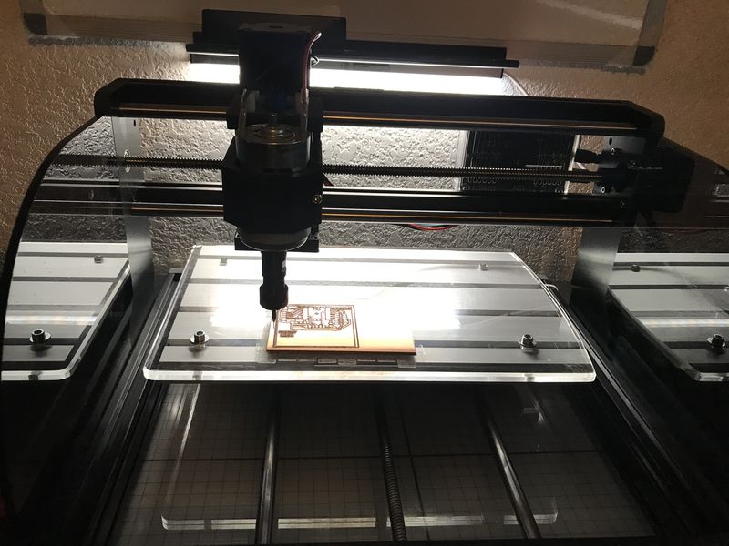
Now I must mill the board. First, I send the traces to MySweety.
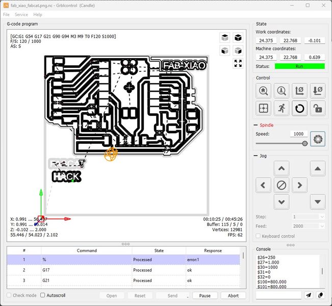
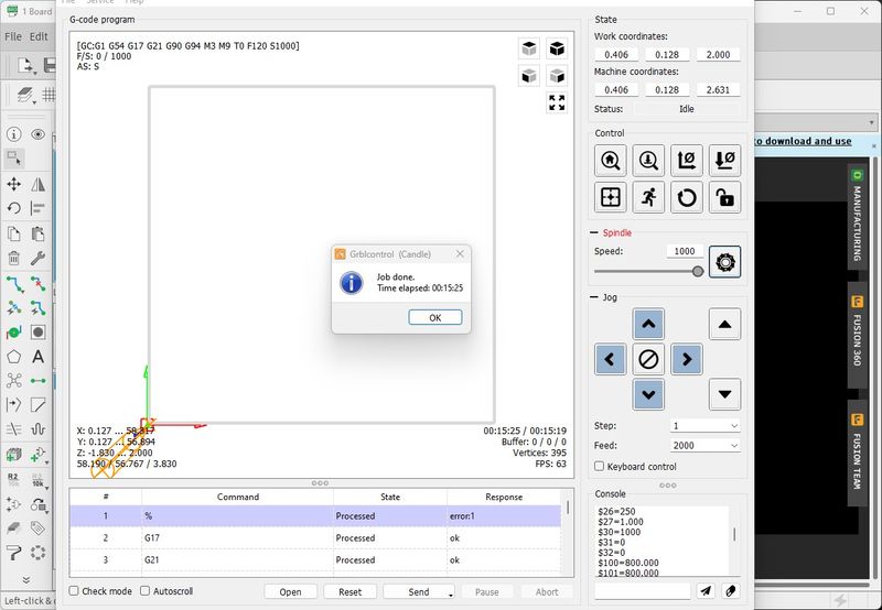
This is the finish time.
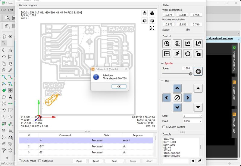
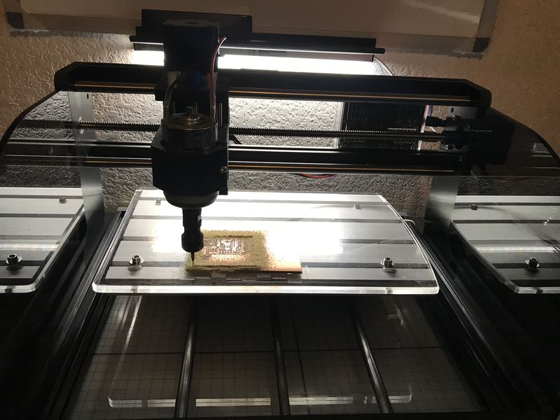
Then I send the borders to MySweety.
This is the finish time.
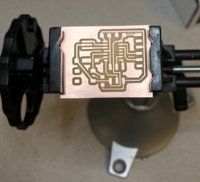
This is the finished board.
The next step is to stuff the board. For that, I will need to collect the parts from the Inventory and place them in a tray. I remembered the mention of a very nice inventory system in the Review for Electronics Design at 51:46 on the video from Fab Lab Kerala called FabStash. Though I don’t have access to login, I like the layout and the print out from the web app. Adrian has a nice web interface for the Fab-XIAO and it can be changed a little to meet my needs one I copy it to the clipboard. Then I paste it into Excel, make changes, then paste it to TableConvert and this is my table.
| Item | References | Value | Price | Quantity | Subtotal |
|---|---|---|---|---|---|
| 1 | PCB Copper Clad Board | uxcell 7X10cm | $0.95 | 1 | $0.95 |
| 2 | R0, R1K1, R470, R4K7 | R_1206 | 0.05 | 4 | $0.20 |
| 3 | D1 | LEDFAB1206 | $0.23 | 1 | $0.23 |
| 4 | SW1 | Button_Omron_B3SN_6.0x6.0mm | $1.00 | 1 | $1.00 |
| 5 | M1 | Module_XIAO-RP2040 | $4.68 | 1 | $4.68 |
| 6 | J1 | Conn_PinHeader_1x06_P2.54mm_Horizontal_SMD | $0.60 | 1 | $0.60 |
| 7 | J2, J2TOP | Conn_PinHeader_1x09_P2.54mm_Horizontal_SMD | $0.90 | 1 | $0.90 |
| 8 | J3 | Conn_PinHeader_2x03_P2.54mm_Vertical_SMD | $0.84 | 1 | $0.84 |
| Total | $9.40 |
This is the updated schematic using the references in the BOM.
This is the updated board using the references in the BOM.
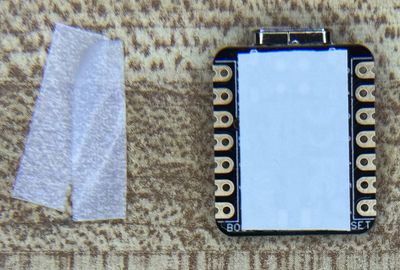
I applied label maker tape to the back of the XIAO RP2040 for extra insulation. This is the tape and the XIAO.
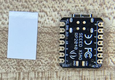
This is with the tape applied. The 12mm tape is the perfect size :)
This is the collection of parts for stuffing the board.
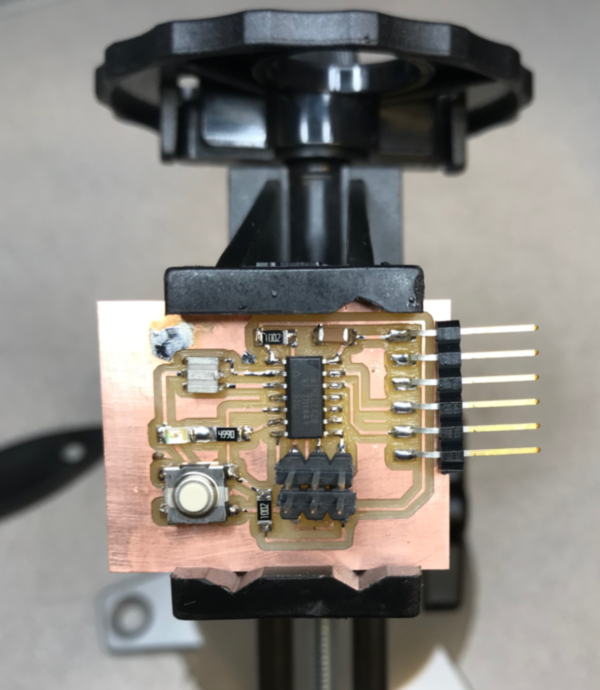
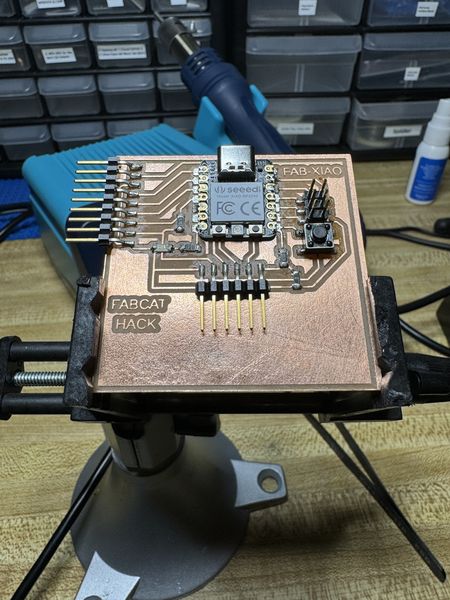
This is the stuffed Fab-XIAO-FABCAT board.
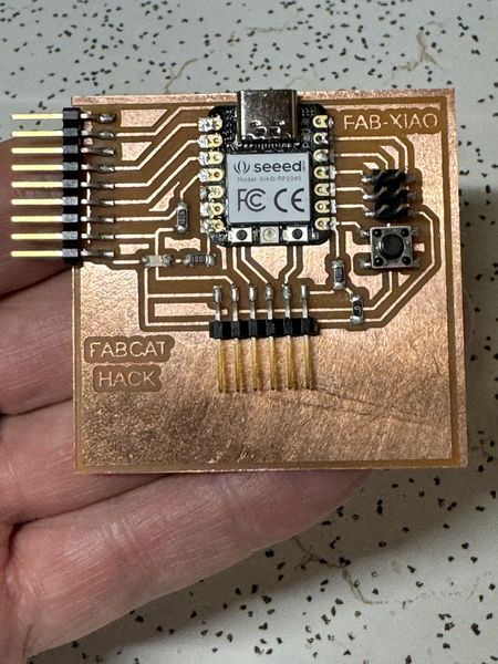
Included a ‘hero shot’:
This is the Hero Shot :)
Testing the Final Project Board
While I was soldering, I tested the connections for the resistors and the Clear Blue LED; they were all successful. Now I will test the board with power to the XIAO RP2040 using the USB-C connection.
Now I have setup the Miniware Digital Power Supply (MDP-P905) to provide a constant 5V and a maximum of 1.0A to the 5v and GND pins of the Fab-XIAO-FABCAT board.
This video shows the supply voltage and current as well as the proper operation of the Fab-XIAO-FABCAT board.
The testing provided valuable data; especially for the required current and power consumption, but this is only for the default setup of the XIAO RP2040. Now I will program the RP2040 to blink the external LED (D1) with the push of a switch (SW1).
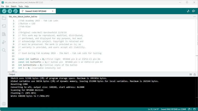
This is the program provided by Adrian Torres for the Fab-XIAO button. As Adrian did, I will upload to the RP2040 using the Arduino IDE 2.3.2. I am using COM4 with the Seeed XIAO RP2040 board selected.
//Fab Academy 2023 - Fab Lab León
//Button + LED
//Fab-Xiao
//
//Original code:Neil Gershenfeld 12/8/19
// This work may be reproduced, modified, distributed,
// performed, and displayed for any purpose, but must
// acknowledge this project. Copyright is retained and
// must be preserved. The work is provided as is; no
// warranty is provided, and users accept all liability.
//
// Used during Fab Academy 2024 - Jim Hart - Fab Lab León for testing

const int ledPin1 = 0;//first light  RP2040 pin 0 or ESP32-C3 pin D6
const int buttonPin = 1;// button pin  RP2040 pin 1 or ESP32-C3 pin D7
int buttonState = 0;//initial state of the button
int i = 0; //variable intensity led

void setup() { //declaration of inputs and outputs
  pinMode(ledPin1, OUTPUT);
  pinMode(buttonPin, INPUT);
}
void loop() {
  buttonState = digitalRead(buttonPin);// we read the state of the button
  if (buttonState == HIGH) { //if we press the button
  digitalWrite(ledPin1, HIGH);
  delay(500);
  digitalWrite(ledPin1, LOW);
  delay(500);
  digitalWrite(ledPin1, HIGH);
  delay(500);
  digitalWrite(ledPin1, LOW);
  delay(500);
  digitalWrite(ledPin1, HIGH);
  delay(2000);
  digitalWrite(ledPin1, LOW);
  delay(1000);

}
  else {  //if we don't press the button
  digitalWrite(ledPin1, LOW);
  }
}
First, I compiled it to be sure there were not errors. Then I uploaded to the RP2040. And received a good report.
Then I tested the button to verify proper operation.
Included original design files (Eagle, KiCad, etc.):
- Included original design files (Eagle, KiCad, etc.):
Design Files Eagle