Input Devices
This week I will learn about input devices. This will include:
Unit Description
Group assignment:
- Probe an input device(s)’s analog and digital signals
- Document your work on the group work page and reflect on your individual page what you learned
Individual assignment:
- Measure something: add a sensor to a microcontroller board that you have designed and read it.
Learning outcomes
- Demonstrate workflows used in sensing something with input device(s) and MCU board
Checklist
Linked to the group assignment page:
-
Linked to the group assignment page:
-
There are two types of assignments, one group and one individual, since I am alone in my personal Fab Lab I will do both. All of my work will be documented here, so there won’t be a group assignment page.
-
Probe an input device(s)’s analog and digital signals
First, I had to research the different tools that we use in the Fab Lab for probing. I consulted with Copilot to get some assistance and had great success. My first prompt was: Sent by you: I have the following tools: Digital multimeter (XL830L), Oscilloscope (ADS1014D and DS213), Logic Analyzer (LA104) and KeeYees USB Logic Analyzer. What is the difference between each of these tools? The response reinforced what I knew and enlightened me on several concepts. The summary is given here:
- Multimeters provide an overview of basic electrical parameters.
- Oscilloscopes visualize waveforms for detailed analysis.
- Logic analyzers focus on digital signals, while mixed-signal variants handle both digital and analog signals.
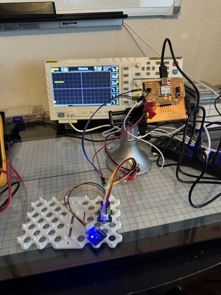
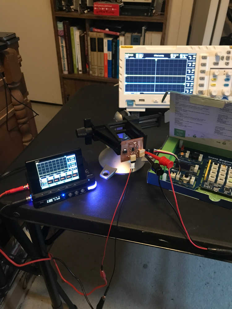
In order to do this, I will need to connect the input devices to my recently made FABCAT board. This is the board I will use in my Final Project and the input devices will be digital and analog temperature sensors.
Using screw terminals and cables mentioned below, I was able to connect the digital temperature sensor (DS18B20) to the board while having convenient connections for probing and monitoring the voltage and waveforms as I operated the board.
This is the setup:
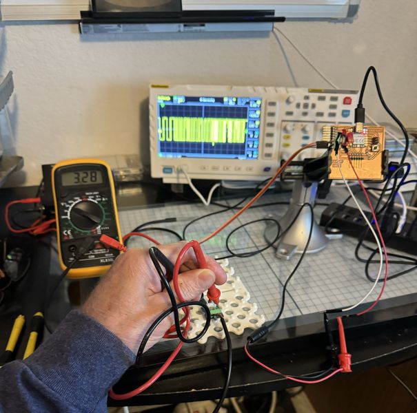
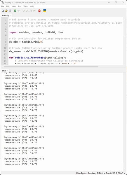
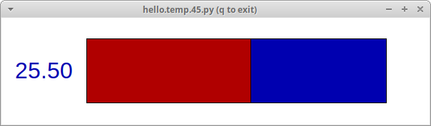
I learned a lot from Copilot and checked the recommendations with my equipment. I first measured the volatage with the multimeter and then connected the ground lead (black) to the ground on the board and connected the positive lead (red) to the 1-wire pin of the temperature sensor (with power turned off). Then I powered on the board and uploaded the code as shown further down the page. This is the serial monitor output from Thonny.
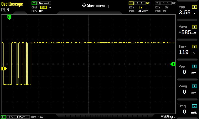
My oscilloscope was set to Normal Trigger mode with the trigger at zero volts. My volts/per division was 1V and my Timebase was set at 1 mSec/per division. This is the signal I displayed on the oscilloscope.
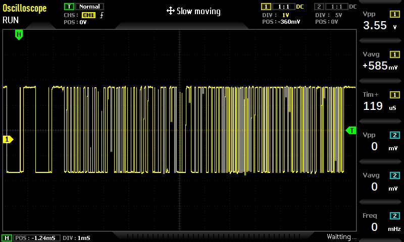
Since there are two pulse signals generated during communications, I captured both. I look forward to learning more about the details of these signals.
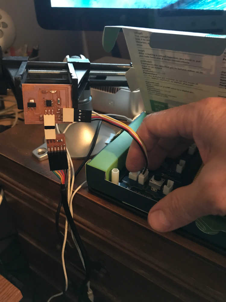
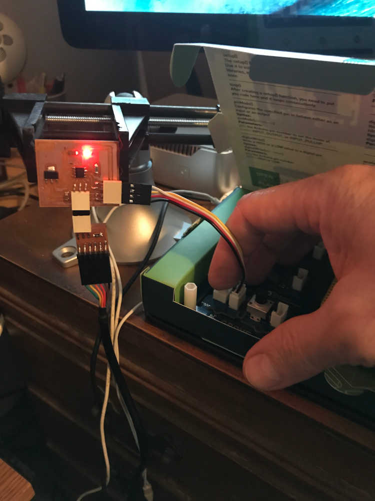
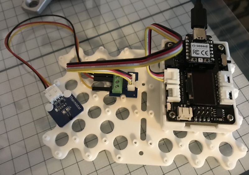
My analog input device will be for temperature as well. I cover the details on the code further down the page with a Seeed Studio XIAO Expansion Board, but I am using the FABCAT board that I made to show the probing here in the group assignment section. I am using the same thermistor sensor that I used below for prototyping my Final Project Temperature Sensing to RGB LED Output.
This is the setup:
This video demonstrates the analog output of the thermistor on the serial monitor as well as the oscilloscope as I touch the thermistor and make the temperature go up.
Documented your design and fabrication process or linked to the board you made in a previous assignment:
- Documented your design and fabrication process or linked to the board you made in a previous assignment:
Results from Fab Academy 2019 cycle:
-
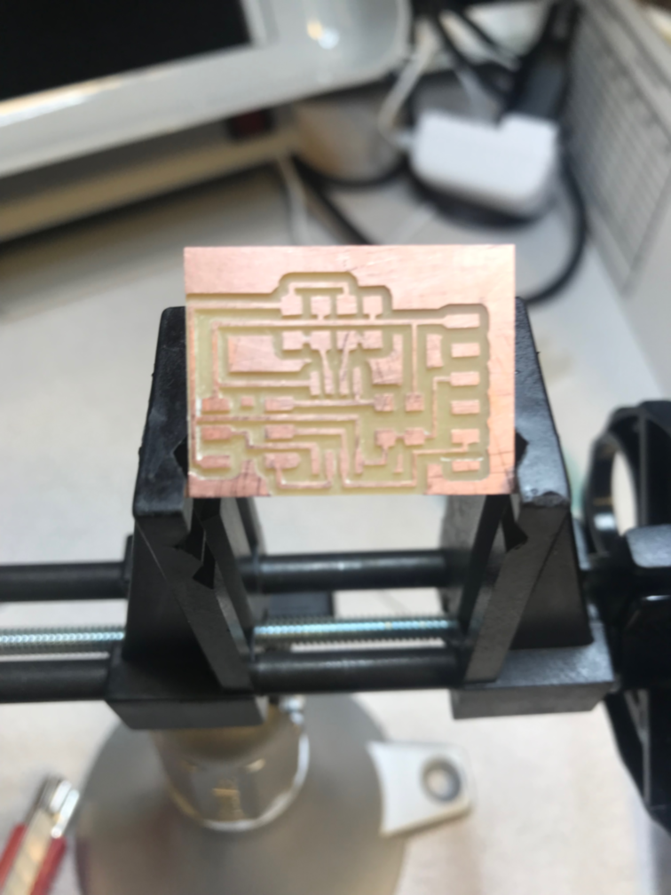
Used the board building workflow of pcb.py coupled with mods. I stood on the shoulders of Neil (our giant :) to get the temperature reading that I will need for the final project. This was more of an imitation/duplication of Neil’s board as I was still learning how to design.
-
Made the board
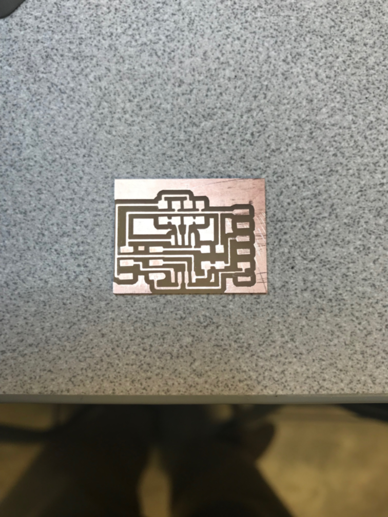
- Stuffed the board
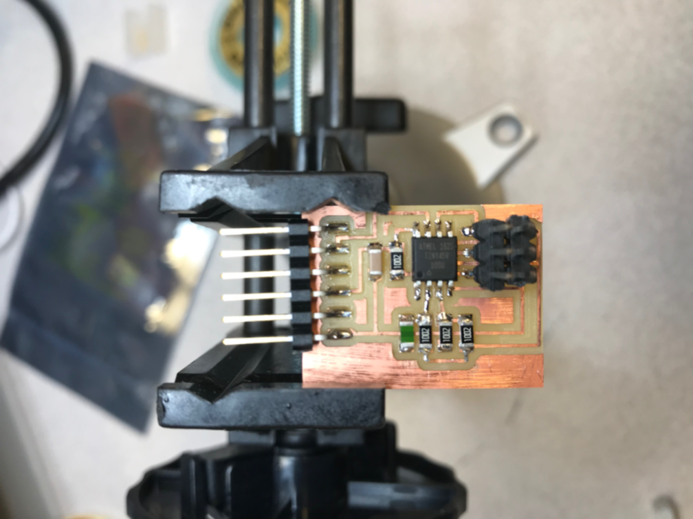
-
Explained the programming process/es you used:
-
Programmed the board and tested it
Code Example
jimhart@jim-Xubuntu3:~/Documents/temperature$ make -f hello.temp.45.make
avr-gcc -mmcu=attiny45 -Wall -Os -DF_CPU=8000000 -I./ -o hello.temp.45.out hello.temp.45.c
avr-objcopy -O ihex hello.temp.45.out hello.temp.45.c.hex;\
avr-size --mcu=attiny45 --format=avr hello.temp.45.out
AVR Memory Usage
----------------
Device: attiny45

Program:     478 bytes (11.7% Full)
(.text + .data + .bootloader)

Data:          0 bytes (0.0% Full)
(.data + .bss + .noinit)


jimhart@jim-Xubuntu3:~/Documents/temperature$ make -f hello.temp.45.make program-usbtiny
avr-objcopy -O ihex hello.temp.45.out hello.temp.45.c.hex;\
avr-size --mcu=attiny45 --format=avr hello.temp.45.out
AVR Memory Usage
----------------
Device: attiny45

Program:     478 bytes (11.7% Full)
(.text + .data + .bootloader)

Data:          0 bytes (0.0% Full)
(.data + .bss + .noinit)


avrdude -p t45 -P usb -c usbtiny -U flash:w:hello.temp.45.c.hex

avrdude: AVR device initialized and ready to accept instructions

Reading | ################################################## | 100% 0.00s

avrdude: Device signature = 0x1e9206 (probably t45)
avrdude: NOTE: "flash" memory has been specified, an erase cycle will be performed
         To disable this feature, specify the -D option.
avrdude: erasing chip
avrdude: reading input file "hello.temp.45.c.hex"
avrdude: input file hello.temp.45.c.hex auto detected as Intel Hex
avrdude: writing flash (478 bytes):

Writing | ################################################## | 100% 0.78s

avrdude: 478 bytes of flash written
avrdude: verifying flash memory against hello.temp.45.c.hex:
avrdude: load data flash data from input file hello.temp.45.c.hex:
avrdude: input file hello.temp.45.c.hex auto detected as Intel Hex
avrdude: input file hello.temp.45.c.hex contains 478 bytes
avrdude: reading on-chip flash data:

Reading | ################################################## | 100% 0.89s

avrdude: verifying ...
avrdude: 478 bytes of flash verified

avrdude: safemode: Fuses OK (E:FF, H:DF, L:62)

avrdude done.  Thank you.
Previous Research and Discoveries
To expand my knowledge, I connected a simple input device to my t412_oled_board.
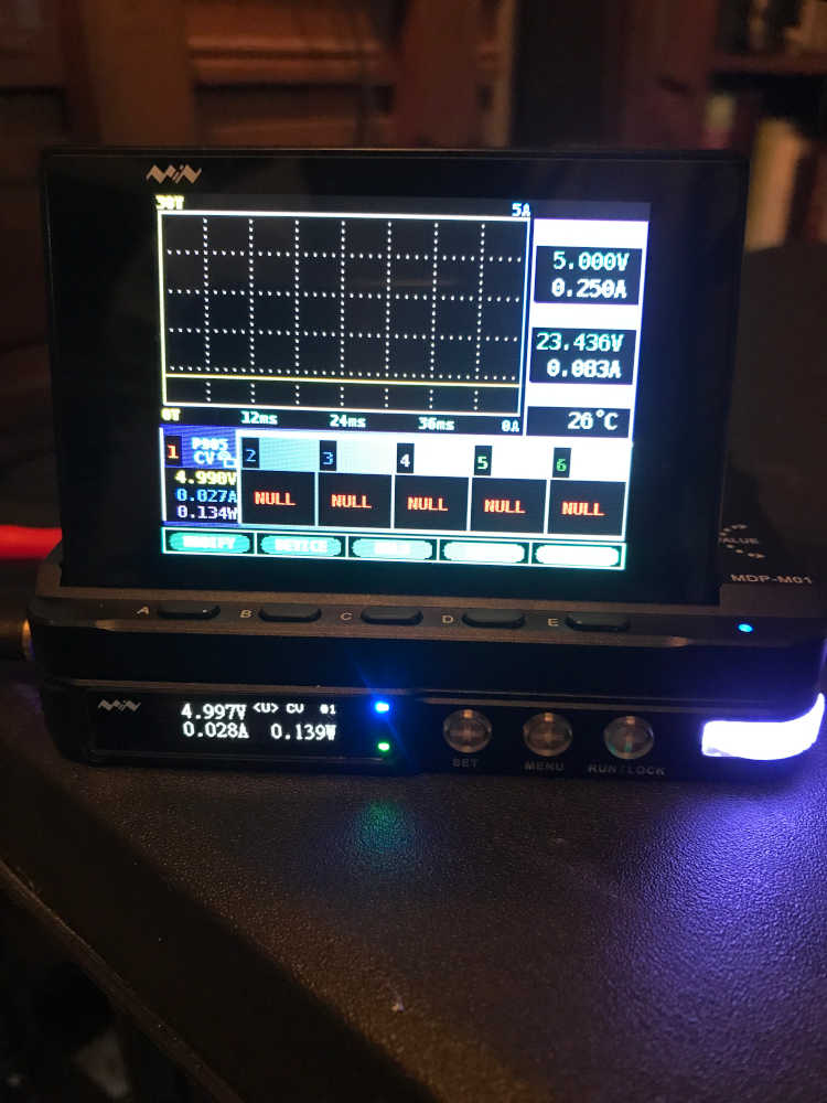
After making the cables mentioned below, I was able to connect the power supply and monitor the voltage, current, and power as I operated the pushbutton.
This is the setup:
This is when the pushbutton is not pushed:
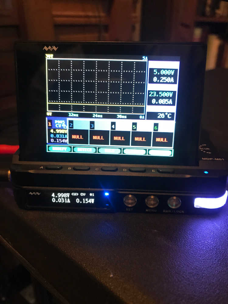
This is when the pushbutton is pushed:
I connected the oscilloscope to the ground and signal wire (SCL) to monitor the voltage change as I pushed the pushbutton. You will have to watch in this video:
- Documented what you learned from interfacing an input device(s) to your microcontroller and how the physical property relates to the measured results:
There are many input devices in the Grove Beginners Kit, Grove Starter Kit for Seeeed XIAO, and the Sunfounder Sensor Kit V2.0 for Arduino; I will demonstrate and document the use of some of these input devices.
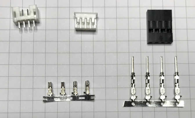
In my personal Fab Lab I have 2.0mm and 2.54mm Connector Kits
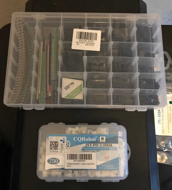
and the crimpers required for these kits.

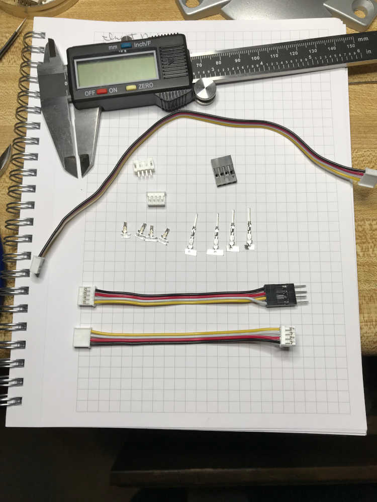
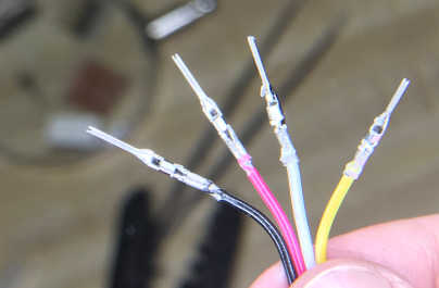
I modified one of the Grove cables to allow interfacing with my t412_oled_board through the OLED Interface.
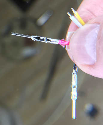
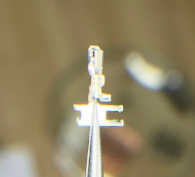
Strip the conductor and align in the pin:
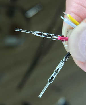
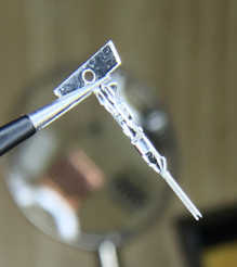
Crimp the pin:
Complete crimping of all pins:
Align pins in the connector:
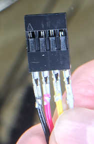
Push pins into connector until the pin is secured:
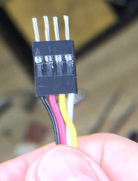
I am using my t412_oled_board that I designed and fabricated in Output Devices week to receive the signals provided by the input devices. The cool thing about this spiral is the through hole connector that you see in the image above. I can mount that on any board and interface with all of the input devices in my kits. In another spiral, I will fabricate input devices for you to make for yourself :) I really like to have connections that are temporary and moveable.
- Explained the programming process/es you used:
The Arduino IDE was used during the programming process. There are examples available for each of the input devices that I modified to use with my t412_oled_board. I started with a pushbutton to keep it simple. We will see where I finish ;)
I used the Button program under File > Examples > 02.Digital > Button
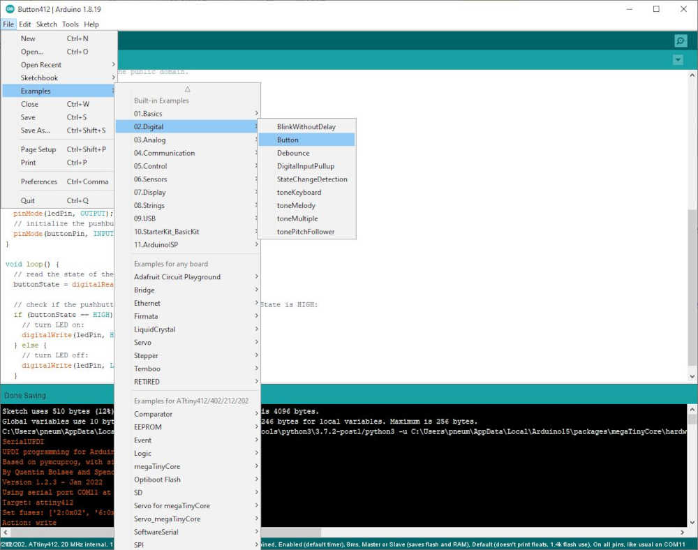
Then I modified it to include the changes needed to use the pushbutton input device:
/*
  Button

  Turns on and off a light emitting diode(LED) connected to digital pin 4,
  when pressing a pushbutton attached to pin 3.

  The circuit:
  - OLED Interface pin 1 is GND (Black wire)
  - OLED Interface pin 2 is +3.3V (Red Wire)
  - OLED Interface pin 3 is SCL is connected to the SIG connection on the button (Yellow Wire)
  - OLED Interface pin 4 is not connected (NC) on the Grove button
  - LED attached from pin 3 to ground through 1 Kohm resistor on ATTiny412 OLED dev board
  - Input device is a momentary normally open pushbutton from Grove Beginner Kit attached to pin 4 on ATTiny412 OLED dev board


  - Note: on most Arduinos there is already an LED on the board
    attached to pin 13. However, this is an ATTiny412 OLED dev board with a SMD Red LED.

  created 2005
  by DojoDave <http://www.0j0.org>
  modified 30 Aug 2011
  by Tom Igoe
  modified 18 Apr 2023
  by Jim Hart For Tiny412: ledPin to pin 4, buttonPin to pin 3

  This example code is in the public domain.

  https://www.arduino.cc/en/Tutorial/BuiltInExamples/Button
*/

// constants won't change. They're used here to set pin numbers:
const int buttonPin = 3;     // the number of the pushbutton pin
const int ledPin =  4;      // the number of the LED pin

// variables will change:
int buttonState = 0;         // variable for reading the pushbutton status

void setup() {
  // initialize the LED pin as an output:
  pinMode(ledPin, OUTPUT);
  // initialize the pushbutton pin as an input:
  pinMode(buttonPin, INPUT);
}

void loop() {
  // read the state of the pushbutton value:
  buttonState = digitalRead(buttonPin);

  // check if the pushbutton is pressed. If it is, the buttonState is HIGH:
  if (buttonState == HIGH) {
    // turn LED on:
    digitalWrite(ledPin, HIGH);
  } else {
    // turn LED off:
    digitalWrite(ledPin, LOW);
  }
}
I uploaded this file using UPDI with the help of Serial UPDI from SpenceKonde and had a successful upload:
Sketch uses 510 bytes (12%) of program storage space. Maximum is 4096 bytes.
Global variables use 10 bytes (3%) of dynamic memory, leaving 246 bytes for local variables. Maximum is 256 bytes.
C:\Users\pneum\AppData\Local\Arduino15\packages\megaTinyCore\tools\python3\3.7.2-post1/python3 -u C:\Users\pneum\AppData\Local\Arduino15\packages\megaTinyCore\hardware\megaavr\2.5.11/tools/prog.py -t uart -u COM11 -b 230400 -d attiny412 --fuses 2:0x02 6:0x04 8:0x00 -fC:\Users\pneum\AppData\Local\Temp\arduino_build_35935/Button412.ino.hex -a write -v
SerialUPDI
UPDI programming for Arduino using a serial adapter
Based on pymcuprog, with significant modifications
By Quentin Bolsee and Spence Konde
Version 1.2.3 - Jan 2022
Using serial port COM11 at 230400 baud.
Target: attiny412
Set fuses: ['2:0x02', '6:0x04', '8:0x00']
Action: write
File: C:\Users\pneum\AppData\Local\Temp\arduino_build_35935/Button412.ino.hex
pymcuprog.programmer - INFO - Setting up programming session for 'attiny412'
pymcuprog.deviceinfo.deviceinfo - INFO - Looking for device attiny412
pymcuprog.serialupdi.physical - INFO - Opening port 'COM11' at '115200' baud
pymcuprog.serialupdi.link - INFO - STCS 08 to 0x03
pymcuprog.serialupdi.link - INFO - STCS 06 to 0x02
pymcuprog.serialupdi.link - INFO - LDCS from 0x00
pymcuprog.serialupdi.link - INFO - UPDI init OK
pymcuprog.serialupdi.link - INFO - STCS 06 to 0x02
pymcuprog.serialupdi.link - INFO - Setting UPDI clock to 8 MHz
pymcuprog.serialupdi.link - INFO - STCS 02 to 0x09
pymcuprog.serialupdi.physical - INFO - Switching to '230400' baud
pymcuprog.serialupdi.application - INFO - SIB: 'tinyAVR P:0D:0-3M2 (02.59B14.0)'
pymcuprog.serialupdi.application - INFO - Device family ID: 'tinyAVR'
pymcuprog.serialupdi.application - INFO - NVM interface: 'P:0'
pymcuprog.serialupdi.application - INFO - Debug interface: 'D:0'
pymcuprog.serialupdi.application - INFO - PDI oscillator: '3M2'
pymcuprog.serialupdi.application - INFO - Extra info: '(02.59B14.0)'
pymcuprog.serialupdi.application - INFO - Using 16-bit UPDI
pymcuprog.serialupdi.link - INFO - LDCS from 0x00
pymcuprog.serialupdi.application - INFO - PDI revision = 0x02
pymcuprog.serialupdi.link - INFO - LDCS from 0x0B
pymcuprog.serialupdi.link - INFO - LDCS from 0x0B
pymcuprog.serialupdi.application - INFO - Entering NVM programming mode
pymcuprog.serialupdi.link - INFO - LDCS from 0x07
pymcuprog.serialupdi.application - INFO - Apply reset
pymcuprog.serialupdi.link - INFO - STCS 59 to 0x08
pymcuprog.serialupdi.application - INFO - Release reset
pymcuprog.serialupdi.link - INFO - STCS 00 to 0x08
pymcuprog.serialupdi.link - INFO - LDCS from 0x0B
pymcuprog.serialupdi.link - INFO - LDCS from 0x0B
pymcuprog.nvm - INFO - No specific initializer for this provider
Pinging device...
pymcuprog.programmer - INFO - Reading device ID...
pymcuprog.serialupdi.application - INFO - SIB: 'tinyAVR P:0D:0-3M2 (02.59B14.0)'
pymcuprog.serialupdi.application - INFO - Device family ID: 'tinyAVR'
pymcuprog.serialupdi.application - INFO - NVM interface: 'P:0'
pymcuprog.serialupdi.application - INFO - Debug interface: 'D:0'
pymcuprog.serialupdi.application - INFO - PDI oscillator: '3M2'
pymcuprog.serialupdi.application - INFO - Extra info: '(02.59B14.0)'
pymcuprog.serialupdi.application - INFO - Using 16-bit UPDI
pymcuprog.serialupdi.link - INFO - LDCS from 0x00
pymcuprog.serialupdi.application - INFO - PDI revision = 0x02
pymcuprog.serialupdi.link - INFO - LDCS from 0x0B
pymcuprog.serialupdi.application - INFO - Device ID from pyupdi = '1E9223' rev 'C'
pymcuprog.nvm - INFO - Device ID: '1E9223'
pymcuprog.nvm - INFO - Device revision: 'C'
pymcuprog.nvm - INFO - Device serial number: 'b'304b444549306e851e1d''
Ping response: 1E9223
Setting fuse 0x2=0x2
Writing literal values...
pymcuprog.programmer - INFO - Write...
pymcuprog.programmer - INFO - Writing 1 bytes of data to fuses...
pymcuprog.programmer - INFO - Write complete.
Verifying literal values...
pymcuprog.programmer - INFO - Reading 1 bytes from fuses...
pymcuprog.programmer - INFO - Verifying...
Action took 0.19s
Setting fuse 0x6=0x4
Writing literal values...
pymcuprog.programmer - INFO - Write...
pymcuprog.programmer - INFO - Writing 1 bytes of data to fuses...
pymcuprog.programmer - INFO - Write complete.
Verifying literal values...
pymcuprog.programmer - INFO - Reading 1 bytes from fuses...
pymcuprog.programmer - INFO - Verifying...
Action took 0.19s
Setting fuse 0x8=0x0
Writing literal values...
pymcuprog.programmer - INFO - Write...
pymcuprog.programmer - INFO - Writing 1 bytes of data to fuses...
pymcuprog.programmer - INFO - Write complete.
Verifying literal values...
pymcuprog.programmer - INFO - Reading 1 bytes from fuses...
pymcuprog.programmer - INFO - Verifying...
Action took 0.19s
Finished writing fuses.
Chip/Bulk erase,
Memory type eeprom is conditionally erased (depending upon EESAVE fuse setting)
Memory type flash is always erased
Memory type lockbits is always erased
...
pymcuprog.programmer - INFO - Erase...
pymcuprog.serialupdi.nvm - INFO - Chip erase using NVM CTRL
Erased.
Action took 0.06s
Writing from hex file...
Writing flash...
pymcuprog.programmer - INFO - Write...
pymcuprog.programmer - INFO - Writing 510 bytes of data to flash...
[==================================================] 8/8
pymcuprog.programmer - INFO - Write complete.
Action took 0.63s
Verifying...
pymcuprog.programmer - INFO - Reading 510 bytes from flash...
pymcuprog.programmer - INFO - Verifying...
Verify successful. Data in flash matches data in specified hex-file
Action took 0.08s
pymcuprog.serialupdi.application - INFO - Leaving NVM programming mode
pymcuprog.serialupdi.application - INFO - Apply reset
pymcuprog.serialupdi.link - INFO - STCS 59 to 0x08
pymcuprog.serialupdi.application - INFO - Release reset
pymcuprog.serialupdi.link - INFO - STCS 00 to 0x08
pymcuprog.serialupdi.link - INFO - STCS 0C to 0x03
pymcuprog.serialupdi.physical - INFO - Closing port 'COM11'
This allowed me to use a pushbutton to control the LED on my t412_oled_board:
- Explained any problems you encountered and how you fixed them:
The crimping process was probably the most difficult part of this week. The 2.0mm connectors are small and the wire is thin.
I have two crimpers, one is ratcheting and one is not. The ratcheting crimper crimped too tight and the pin broke off the first two attempts. On the third attempt the insulation was too far into the front and did not have continuity when I tested it with a multimeter. The fourth attempt was successful. I decided to use the non-ratcheting crimper and had much better results. After completing the two cables, I measured the width of the pins and found that the 2.54mm pins are 1.6mm wide rather than 1.3mm;
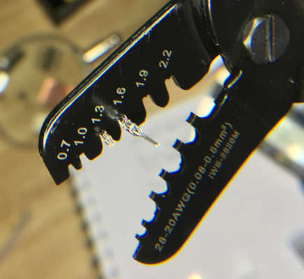
although they crimped okay, I could get a cleaner looking crimp by using the correct size. Lesson learned! It is a very tedious process, but a valuable skill for interfacing devices.
Included a ‘hero shot’ of your board:
- Included a ‘hero shot’ of your board:
Prototyping for the Final Project
-
In an effort to focus my attention on the Final Project (so I can finish Fab Academy), my Remote Instructor, Pablo gave me an assignment to demonstrate the concept of giving an output (RGB LED) based on an input (temperature sensor). First, I needed to make a QuenTorres swd+uart adapter+hello board - XIAO RP2040 that I made in Electronics Production week to complete this assignment, so I ran out of time. However, I will still finish this assignment as I can.
-
I have a lot of learning material that I have wanted to use, so I will document the learning process here. My plan is to use the SunFounder Sensor Kit V2.0 to become familiar with the concept. I plan to use the RGB LED Module
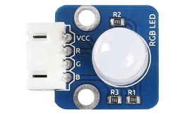
And the Thermistor Module
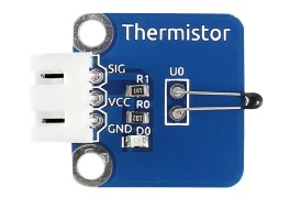
-
The tutorial calls for an Arduino, but I plan to use the XIAO RP2040 since my Instructor recommended this. I also have a nice development board to help me do this Seeed Studio XIAO Starter Kit I will be using the development board tutorial by SeeedStudio. So here we go.
-
First, I had to download and install Arduino IDE since this is a newer computer than the one I have been developing with. Seeed Studio gave me the link in the tutorial. Next, I had to add Seeed Studio XIAO to Arduino IDE. Since I have many of their boards, I added all three links as they recommended. It took quite a while to download. All three boards were installed.
-
Next I connected the RP2040 that I used in the QuenTorres board and plugged it into the Seeed Studio XIAO Expansion Board. I followed the instructions, but still received an error as before. What appears to be the RP2040 mounting its uf2 drive showed that drive in the Port list, so I selected that drive and tried again. It worked that time and the Port then went back to COM8. This is the output:
Sketch uses 52260 bytes (2%) of program storage space. Maximum is 2093056 bytes.
Global variables use 10232 bytes (3%) of dynamic memory, leaving 251912 bytes for local variables. Maximum is 262144 bytes.
Resetting COM8
Converting to uf2, output size: 140288, start address: 0x2000
Scanning for RP2040 devices
Flashing F: (RPI-RP2)
Wrote 140288 bytes to F:/NEW.UF2
-
So what I thought was a coding error before, was a misunderstanding on my part. Another learning opportunity! Once I communicated with the board, it worked every time.
-
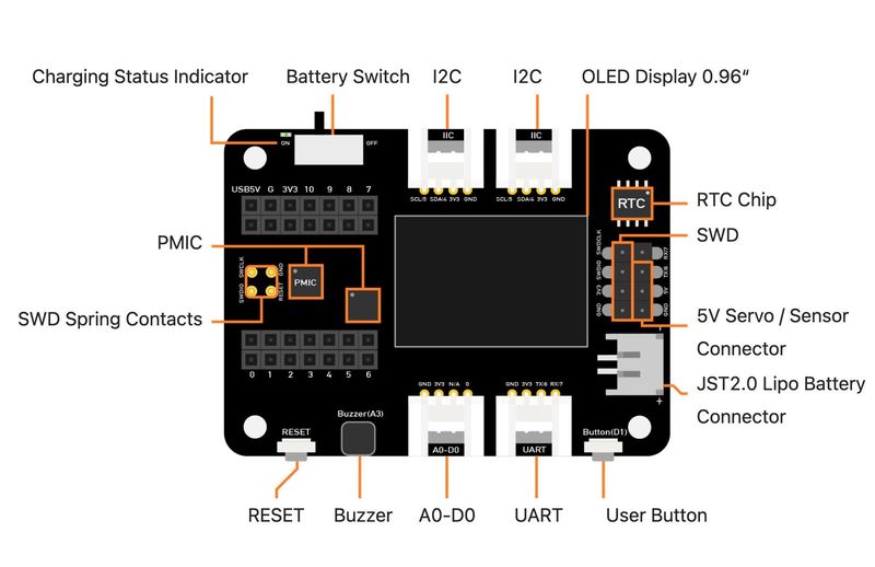
Now that I am on a roll, I will introduce you to the Seeed Studio XIAO Expansion Board. After I have a handle on the process and the programming, I hope to demonstrate with the QuenTorres.
-
This is the Seeed Studio XIAO Expansion Board.
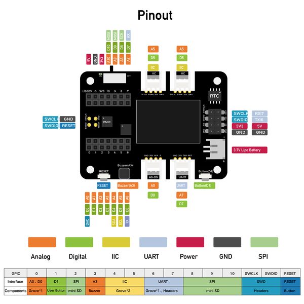
- This is the Seeed Studio XIAO Expansion Board pinout.
-
It is a very versatile board and I hope to make something similar in another spiral. For now, I will use it to detect temperature with the thermistor module.
-
As an interface between the modules, I will use a Grove Screw Terminal module
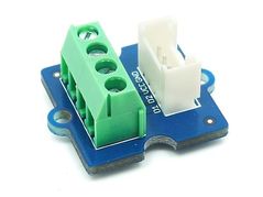
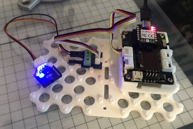
- This enables me to adapt a 3-wire device to a 4-wire connector without fabricating the cable. I will do this later, but this is for prototyping. Here you have the setup of the Temperature Prototype.
- This is the code I obtained from the Sensor Kit V2.0 for Arduino. It has been modified/commented out lines to exclude the use of a LCD display. I will only be using the serial monitor to see what is happening.
#include <Wire.h>
// #include <LiquidCrystal_I2C.h>
// initialize the library with the numbers of the interface pins
// LiquidCrystal_I2C lcd(0x27,16,2);  // set the LCD address to 0x27 for a 16 chars and 2 line display

#define analogPin  A0 //the thermistor attach to
#define beta 3950 //the beta of the thermistor
#define resistance 10 //the value of the pull-up resistor


void setup()
{
  // set up the LCD's number of columns and rows:
  // lcd.init();  //initialize the lcd
  // lcd.backlight();  //open the backlight
  Serial.begin(9600);
}

void loop()
{
  long a =1023 - analogRead(analogPin);  //read thermistor value
  Serial.print("Raw reading ");
  Serial.println(a);
  //the calculating formula of temperature
  float tempC = beta /(log((1025.0 * 10 / a - 10) / 10) + beta / 298.0) - 273.0;
  float tempF = 1.8*tempC + 32.0;
  Serial.print("Centigrade ");
  Serial.println(tempC);
  Serial.print("Fahrenheit ");
  Serial.println(tempF);
  Serial.println("");
  delay(1000);

  // // Print a message of "Temp: "to the LCD.
  // lcd.setCursor(0, 0);// set the cursor to column 0, line 0
  // lcd.print("Temp: ");  // Print a message of "Temp: "to the LCD.
  // lcd.print(tempC); // Print a centigrade temperature to the LCD.
  // // Print the unit of the centigrade temperature to the LCD.
  // lcd.write(char(223));
  // lcd.print("C");//print the unit" ℃  "
  // lcd.setCursor(0, 1);// set the cursor to column 0, line 1
  // lcd.print("Fahr: ");
  // lcd.print(tempF);// Print a Fahrenheit temperature to the LCD.
  // lcd.write(char(223)); // Print the unit of the Fahrenheit temperature to the LCD.
  // lcd.print(" F");//print the unit"°F"
  // delay(200); //wait for 100 milliseconds
}
- First I plug in the USB to the XIAO RP2040 I have mounted on the expansion board.
- Now I communicate with the XIAO using the Arduino IDE and open the analogRes.ino file.
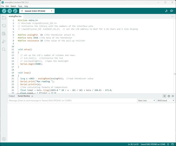
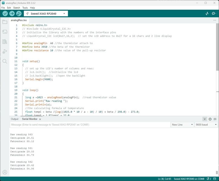
- I Click Upload and the file is compiled and uploaded and you can see the output in the Serial Monitor

- The Fahrenheit temperature is about 73 degrees in my Fab Lab and that is being displayed. When I touch the thermistor for about 30 seconds, you can see the temperature rises to almost 85 degrees.
-
This concludes the test of the thermistor, now on to the RGB module :)
-
Now that I understand the temperature sensing using a trusted module, I need to shift to a temperature sensor that is waterproof. I have been following Random Nerd Tutorials (RNT) since 3/23/2023 and they have inspired me in so many ways. Recently, they sent me an offer for their new ebook Learn Raspberry Pi Pico/Pico W with MicroPython that arrived just in time. When I browsed through the book, I found a lesson on the DS18B20 Addressable Temperature Sensor. I had been experimenting with the LM75 during Networking and Communications, as well as the THERMISTOR NTC 10KOHM 3750K 1206 on Neil’s hello.temp.45 board I made above. I was almost ready to use them and waterproof the boards when this RNT book showed up; very timely! The tutorial begins with the through-hole package, but shows the waterproof version too. I was really excited :)
-
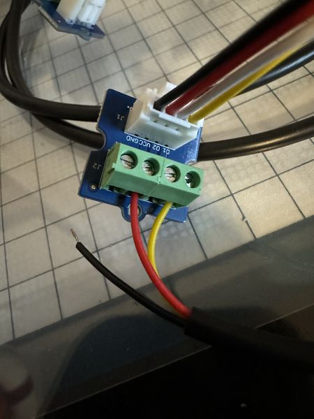
The DS18B20 requires a 4.7Kohm pull-up resistor between the 3.3V and the Data line. At first I used a through-hole resistor like those provided by the vendor, but I modified the Grove Screw Terminal by soldering a 1206 SMD 4.7Kohm resistor between the JST connector pins on the bottom of the board.
-
I had been using Arduino IDE as the programming software, so I thought I would try that first. I installed the Arduino library for the Maxim Integrated DS18B20 1-Wire temperature sensor provided by matmunk Mathias Munk Hansen and used the Single detector code and received the following error:
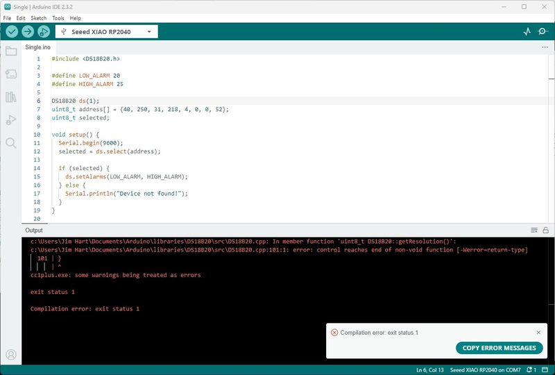
-
I spent some time trying to learn how to resolve the issue, but ultimately I decided to follow the tutorial provided by RNT. This required switching to Thonny and using MicroPython. I discussed the process of installing MicroPython in Embedded Programming toward the bottom of the page. Make sure you boot the RPi Pico/XIAO RP2040 to enter the bootloader by holding down the Boot switch while pressing and releasing the Reset switch before installing MicroPython.
-
I connected the DS18B20 sensor to the UART port on the Seeed Studio Dev Board; this provides 3.3V, Ground, and the UART D7(RX) or GPIO 1.
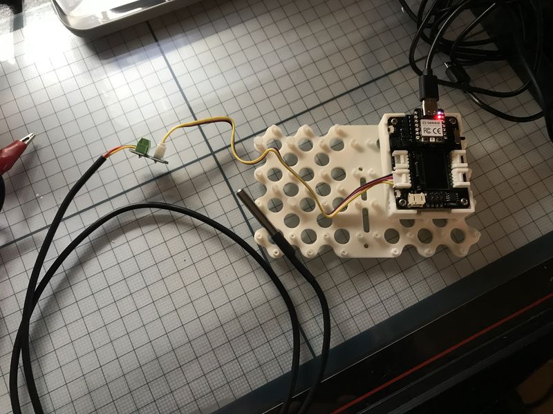
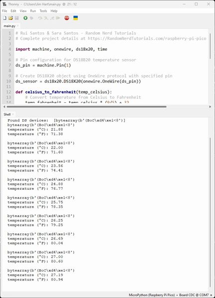
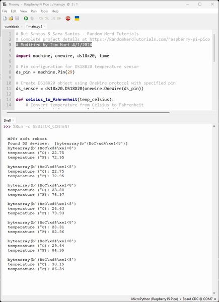
- I ran the following code from the RNT tutorial:
# Rui Santos & Sara Santos - Random Nerd Tutorials
# Complete project details at https://RandomNerdTutorials.com/raspberry-pi-pico-w-micropython-ebook/
# Modified by Jim Hart 4/1/2024

import machine, onewire, ds18x20, time

# Pin configuration for DS18B20 temperature sensor
ds_pin = machine.Pin(1)

# Create DS18X20 object using OneWire protocol with specified pin
ds_sensor = ds18x20.DS18X20(onewire.OneWire(ds_pin))

def celsius_to_fahrenheit(temp_celsius):
    # Convert temperature from Celsius to Fahrenheit
    temp_fahrenheit = temp_celsius * (9/5) + 32
    return temp_fahrenheit

# Scan for DS18B20 sensors and print their ROM addresses
roms = ds_sensor.scan()
print('Found DS devices: ', roms)

while True:
    # Initiate temperature conversion for all sensors
    ds_sensor.convert_temp()
    time.sleep_ms(750)  # Wait for the conversion to complete (750 ms is recommended)

    for rom in roms:
        print(rom)

        # Read temperature in Celsius from the sensor
        temp_c = ds_sensor.read_temp(rom)

        # Convert Celsius temperature to Fahrenheit
        temp_f = celsius_to_fahrenheit(temp_c)

        # Print the temperature readings
        print('temperature (ºC):', "{:.2f}".format(temp_c))
        print('temperature (ºF):', "{:.2f}".format(temp_f))
        print()

    time.sleep(5)  # Wait for 5 seconds before taking readings again
And this is the response with temperature rising due to me holding the sensor in my hand:
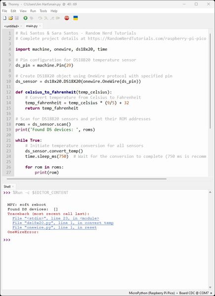
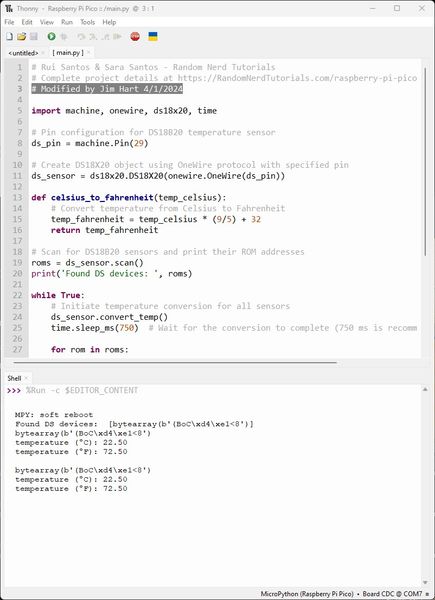
Now that I have fabricated the Fab_XIAO_FABCAT board and tested it, I will test the DS18B20 temperature sensor that I have attached to Pin 29. I will be using Thonny to upload MicroPython as I did before.
First, I had to install MicroPython on the XIAO RP2040 and then Stop/Restart. Thankfully, the main.py code was still in the Thonny IDE, so all I had to do was change the machine.Pin(1) to machine.Pin(29) and connect the DS18B20 temperature sensor to that Pin.
Unfortunately, I did not receive the response from the RP2040 like I did before.
By this time, I had spent most of the day fabricating the board and doing initial testing with great success. This change in flow was discouraging but did not dampen my enthusiasm or thought flow. I immediately started taking voltage measurements with a multimeter and found 3.3v where it was supposed to be, but there were some fluctuations. I needed to rest, but I did not stop thinking about it. Did I need to reflow the solder joints for the RP2040…etc. So many questions. I didn’t go to sleep for a while due to thinking. I finally drifted away to get some rest. I woke up about two hours later and remembered the 4.7Kohm pull-up resistor I had soldered on the screw terminal board for the DS18B20 temperature sensor AND that I had included the resistor on the Fab_XIAO_FABCAT board for this purpose. I was encouraged by this thought, but I knew I had to get more sleep. I couldn’t wait to check this out.
After the FAB City meeting, I checked my work. Sure enough, I left the screw terminal with the pull-up resistor in place.
So, this is my setup to interface with the Fab_XIAO_FABCAT board for prototyping and testing. I have screw terminal that have the Grove JST-PH socket that allows me to quickly change connections.
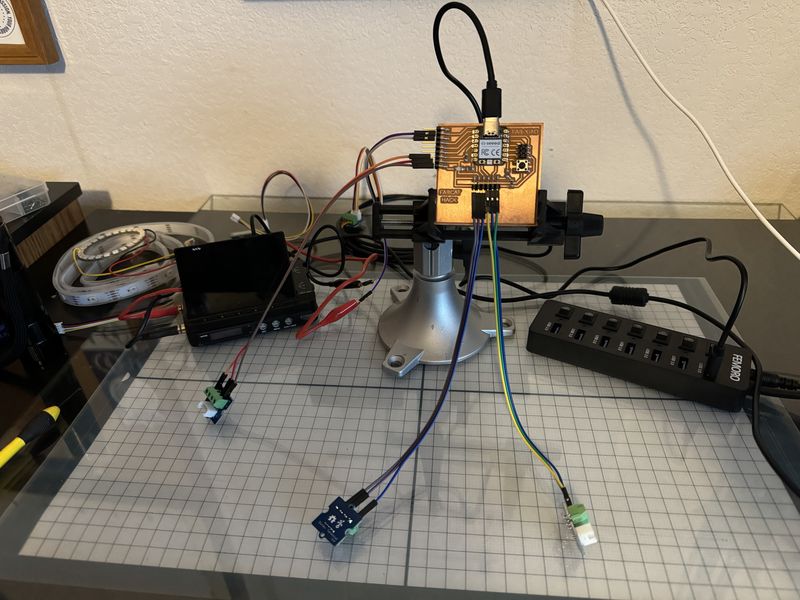
And this is the setup for interfacing the DS18B20 temperature sensor with the Fab_XIAO_FABCAT board. Notice that I have two screw terminals involved.
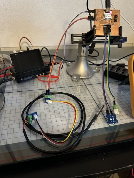
It seemed easier to keep the screw terminal connected to the DS18B20 temperature sensor, but I forgot about the resistor :)
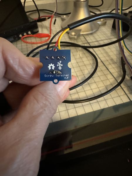
This is the screw terminal to connect to the Fab_XIAO_FABCAT board.
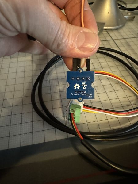
This is the screw terminal to connect to the DS18B20 temperature sensor.
So now I will switch out the screw terminal with the resistor for one without a resistor…HOLD IT! When I picked up the screw terminal with the resistor, the ground wire came out!
Rather than change out the screw terminal I decided to try it by plugging the ground wire back in and tightening the screw. Guess what?! Yep, it works :)
WooHoo!!!
I went ahead and changed out the screw terminal so I could simulate the way it will be in operation and it worked as well :)
This concludes my testing of the DS18B20 temperature sensor as an input device for the Fab_XIAO_FABCAT board. Now on to the Grove Water Sensor. This is a new one for me but I think it is important since my Final Project will be in the water.
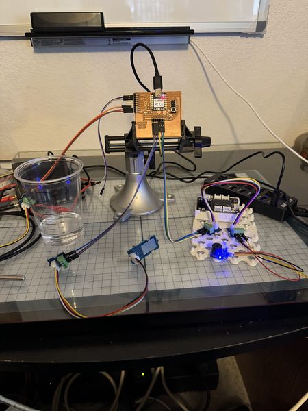
This is my setup to interface with the Fab_XIAO_FABCAT board for prototyping and testing. I have screw terminals that have the Grove JST-PH socket that allows me to quickly change connections. The Grove Water Sensor is connected through a screw terminal and a jumper. I will be using a SunFounder Passive Buzzer for an output and connect it to the Fab_XIAO_FABCAT board where the Neopixel would normally be connected. Since the Passive buzzer has 3 wires, I will use screw terminals as the interface.
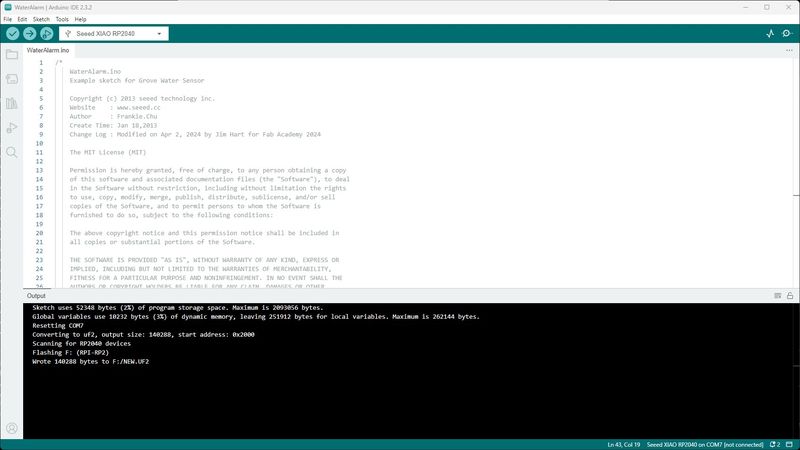
Now I will upload the following code provided by Seeed Studio and modified for the Pins I will be using Pin 7 for the Water Sensor and Pin 6 for the Passive Buzzer.
/*
    WaterAlarm.ino
    Example sketch for Grove Water Sensor

    Copyright (c) 2013 seeed technology inc.
    Website    : www.seeed.cc
    Author     : Frankie.Chu
    Create Time: Jan 18,2013
    Change Log : Modified on Apr 2, 2024 by Jim Hart for Fab Academy 2024

    The MIT License (MIT)

    Permission is hereby granted, free of charge, to any person obtaining a copy
    of this software and associated documentation files (the "Software"), to deal
    in the Software without restriction, including without limitation the rights
    to use, copy, modify, merge, publish, distribute, sublicense, and/or sell
    copies of the Software, and to permit persons to whom the Software is
    furnished to do so, subject to the following conditions:

    The above copyright notice and this permission notice shall be included in
    all copies or substantial portions of the Software.

    THE SOFTWARE IS PROVIDED "AS IS", WITHOUT WARRANTY OF ANY KIND, EXPRESS OR
    IMPLIED, INCLUDING BUT NOT LIMITED TO THE WARRANTIES OF MERCHANTABILITY,
    FITNESS FOR A PARTICULAR PURPOSE AND NONINFRINGEMENT. IN NO EVENT SHALL THE
    AUTHORS OR COPYRIGHT HOLDERS BE LIABLE FOR ANY CLAIM, DAMAGES OR OTHER
    LIABILITY, WHETHER IN AN ACTION OF CONTRACT, TORT OR OTHERWISE, ARISING FROM,
    OUT OF OR IN CONNECTION WITH THE SOFTWARE OR THE USE OR OTHER DEALINGS IN
    THE SOFTWARE.
*/

/*macro definition of water sensor and the buzzer*/
#define WATER_SENSOR 7
#define BUZZER 6
void setup() {
    pins_init();
}
void loop() {
    if (isExposedToWater()) {
        soundAlarm();
    }
}
void pins_init() {
    pinMode(WATER_SENSOR, INPUT);
    pinMode(BUZZER, OUTPUT);
}
/************************************************************************/
/*Function: When the sensor is exposed to the water, the buzzer sounds  */
/*          for 2 seonds.                                               */
void soundAlarm() {
    for (uint8_t i = 0; i < 20; i ++) {
        digitalWrite(BUZZER, HIGH);
        delay(50);
        digitalWrite(BUZZER, LOW);
        delay(50);
    }
}
/************************************************************************/
/*Function: Determine whether the sensor is exposed to the water        */
/*Parameter:-void                                                       */
/*Return:   -boolean,if it is exposed to the water,it will return ture. */
boolean isExposedToWater() {
    if (digitalRead(WATER_SENSOR) == LOW) {
        return true;
    } else {
        return false;
    }
}
I successfully uploaded WaterAlarm.ino after booting into the bootloader by pressing and holding the Boot button on the RP2040 while momentarily pressing the Reset button.
Now I will submerge the Water Sensor in water while I record the event.
Included original design files and source code:
-
Included original design files and source code: