Output Devices
This week I will learn about output devices. This will include:
Unit Description
Group assignment:
- Measure the power consumption of an output device.
- Document your work on the group work page and reflect on your individual page what you learned.
Individual assignment:
- Add an output device to a microcontroller board you’ve designed and program it to do something.
Learning outcomes
- Demonstrate workflows used in controlling an output device(s) with MCU board you have designed.
Checklist
Linked to the group assignment page
-
Linked to the group assignment page:
-
There are two types of assignments, one group and one individual, since I am alone in my personal Fab Lab I will do both. All of my work will be documented here, so there won’t be a group assignment page.
Documented how you determined power consumption of an output device with your group:
- Documented how you determined power consumption of an output device with your group:
I have some measurements that I did during the Fab Academy 2019 cycle; they are documented below. However, they were direct readings and were not the result of a microcontroller driving an output device; I will document that here:
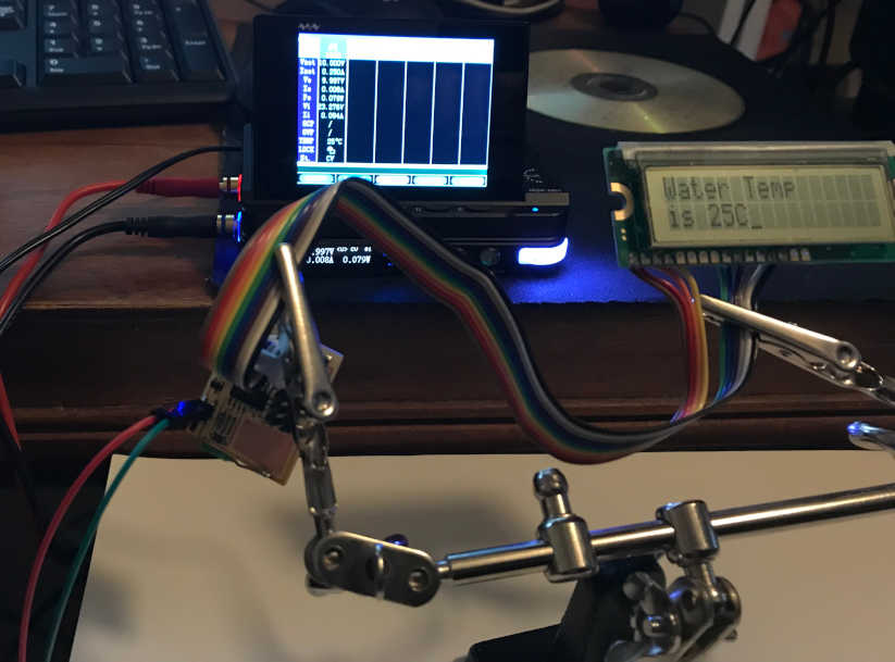
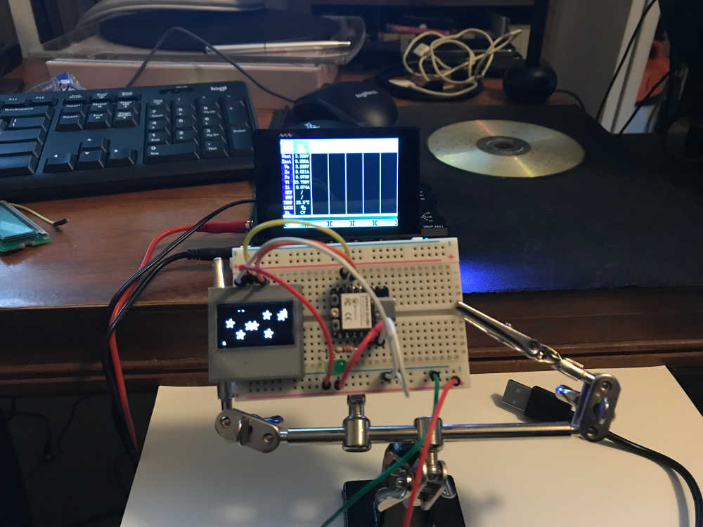
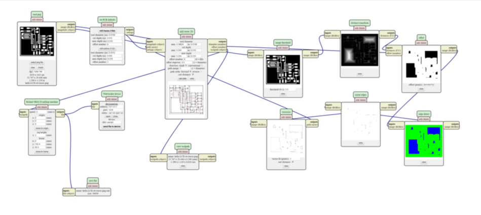
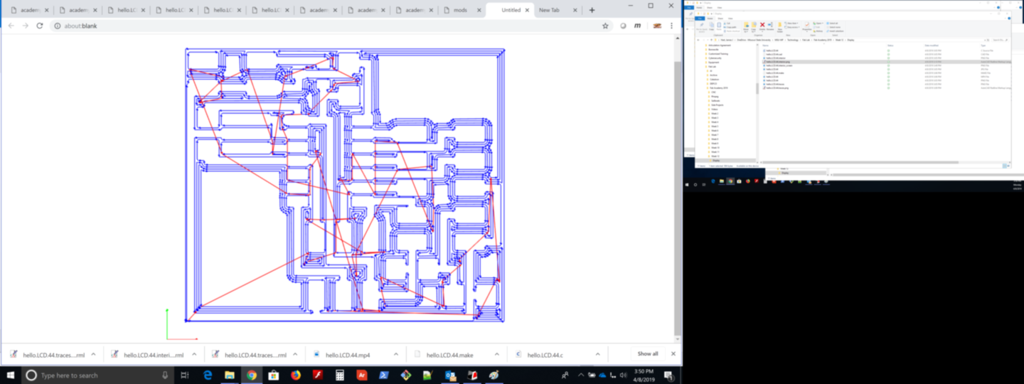
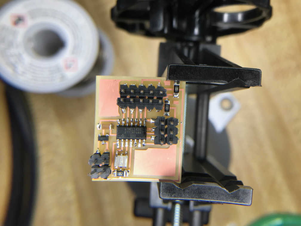
- I setup a breadboard to prototype my microcontrollers before actually designing and making a development board with a microcontroller driving an output. I did fabricate the board Neil shared with us that drives a LCD display. It has an attiny44 as the mcu. I used Neil’s C code and modified the message. This is the power used during operation:
-
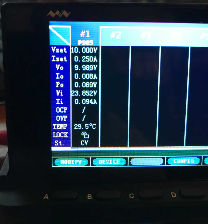
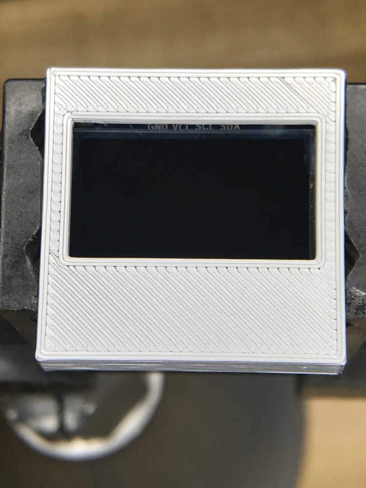
The image above shows the screen of the Smart Digital Monitor (MDP-M01) that is sitting on the Digital Power Supply (MDP-P905) that you can see in the below image. Both are made by SainSmart and come as a unit pair: SainSmart MDP-XP Mini Digital Programmable Power Supply Set with 30V/5A 90W 2.4G Wireless Connection, 2.8 Inch TFT Screen It was part of the Fab Academy Inventory in 2021, but I think they have a newer version now. It is an awesome troubleshooting and debugging tool as well as a portable power supply.
-
PLEASE READ THE MDP-P905 AND MDP-M01 MANUALS BEFORE OPERATING. To setup the Mini Digital Power System, I plug the MDP-M01 into the MDP-P905 with the provided cable. Provide power to the MDP-P905 with an AC/DC power adapter or a USB-C connector.
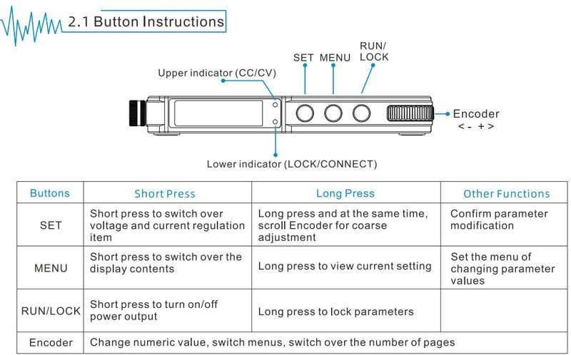
- Turn on the MDP-P905 by pressing the Run/Lock Button. Press Menu to toggle between the Input and Output menus until Output (voltage/current) are displayed on the small screen to the left. Press Set to select Voltage and/or Current and adjust the setting using the Encoder (Wheel) to the desired value.
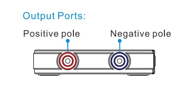
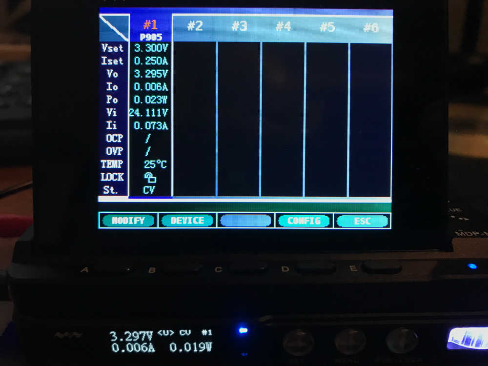
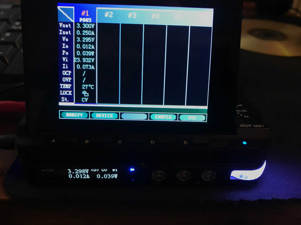
Attach the Red (positive) lead into the Red (postive pole) output port. Attach the Black (negative) lead into the Blue (Negative pole) output port. Attach these leads to the appropriate connections on the tested device. Push Run button to begin supplying power. The below screen provides the status of the values in a more readable format, but does not alter the operation of the MDP-P905.
- In the live image above, the values from device #1 are displayed in the first column. It there were other devices connected wirelessly, they would be displayed in the other columns…many capabilities.
- That is the basic operation for applying voltage to a device. There are many other capabilities covered in the manual.
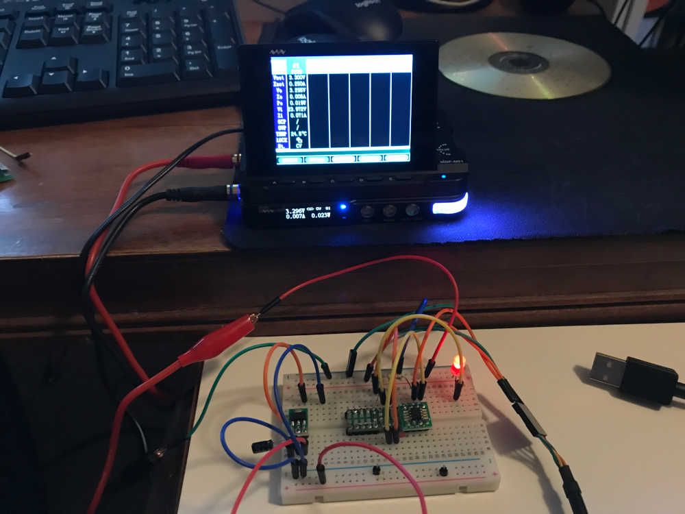
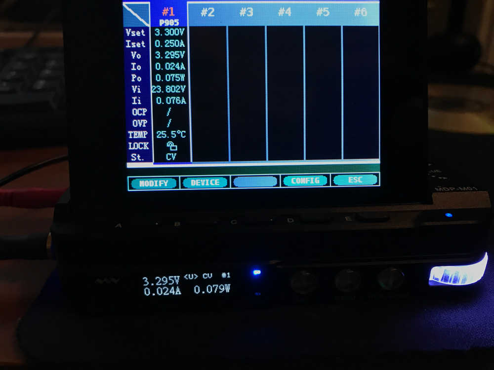
- This is the prototyped attiny412 blinking the LED and the power used during operation:
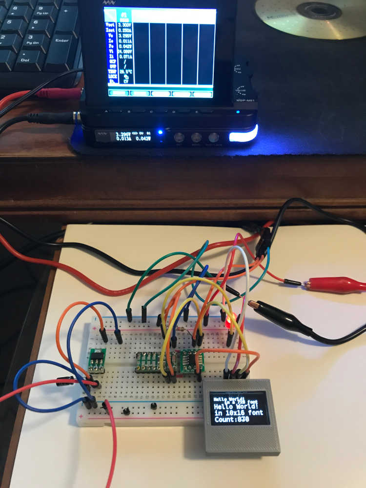
- This is the prototyped XIAO ESP32C3 operating an OLED and the power used during operation:
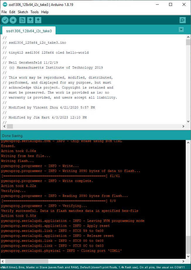
- And I am so happy to add this prototype of the attiny412 operating an OLED and the power used during operation:
It is difficult to tag each moment of learning, design and fabrication, programming processes, and problems solved because they are interrelated, integrated and occur throughout this learning experience. Therefore, I am listing these requirements at the beginning to let you know they occurred in various order throughout; I hope you enjoy the experience like I did :) I’ll do my best to document what happened.
Documented what you learned from interfacing output device(s) to microcontroller and controlling the device(s):
- Documented what you learned from interfacing output device(s) to microcontroller and controlling the device(s):
Linked to the board you made in a previous assignment or documented your design and fabrication process if you made a new board:
- Linked to the board you made in a previous assignment or documented your design and fabrication process if you made a new board:
Explained the programming process/es you used:
- Explained the programming process/es you used:
Explained any problems you encountered and how you fixed them:
- Explained any problems you encountered and how you fixed them:
My method of design may be a bit unorthodox to standard engineering practices, but my way enables me to touch things to organize them in my mind; I guess you could say I am hardware oriented although I do spend a lot of time in software. My goal for this assignment is to use an OLED to display temperature since that was one on my original final project ideas. Since this will be remotely read, I will design this spiral around the XIAO ESP32C3, but I will begin by learning with the XIAO RP2040 since I have tested it and confirmed its operation. Once I test the OLED on the RP2040, I will shift to the ESP32C3. Prototyping will begin on a breadboard to operationally test then design a pcb for both devices.
The OLED is a prefabbed board with an exposed back and 4 pins for power and I2C communications.
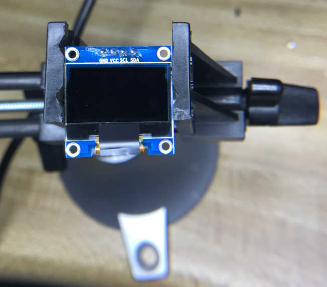
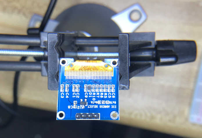
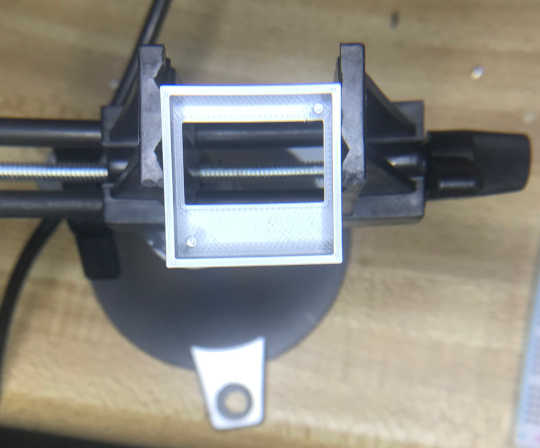
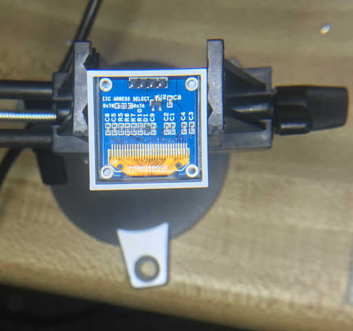
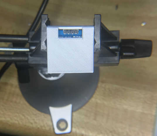
I thought it would be better to have a case for it, so I searched for one and found 0.96” OLED case by floz on thingiverse I setup my 3D printer, warmed it up and sent the file as g-code provided from the PrusaSlicer application. I am so glad I know how to do that :) I intend to modify the design for my final project.
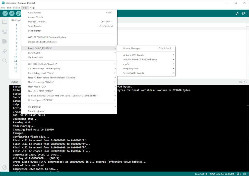
- I began by getting the RP2040 to blink an external LED. Then I tried to use a tutorial to get an output from the OLED. There were dependencies that I could not make work, so I went directly to the ESP32C3 instead. I eventually got an external LED to blink, but I was expecting an LED on the board to blink; this didn’t happen, so I fussed with the boot and reset buttons to no avail. I finally reread the instructions, after much frustration, to find that there is no LED on the dev board and an external LED along with a resistor is required. I uploaded the blinkesp32.ino provided during the SeeedStudio XIAO_ESP32C3_Getting_Started tutorial to the board using Arduino IDE 2.0.4 directly through USB and it worked.
Sketch uses 219040 bytes (16%) of program storage space. Maximum is 1310720 bytes.
Global variables use 15692 bytes (4%) of dynamic memory, leaving 311988 bytes for local variables. Maximum is 327680 bytes.
esptool.py v4.5.1
Serial port COM6
Connecting...
Chip is ESP32-C3 (revision v0.4)
Features: WiFi, BLE
Crystal is 40MHz
MAC: 34:85:18:03:58:f8
Uploading stub...
Running stub...
Stub running...
Changing baud rate to 921600
Changed.
Configuring flash size...
Flash will be erased from 0x00000000 to 0x00003fff...
Flash will be erased from 0x00008000 to 0x00008fff...
Flash will be erased from 0x0000e000 to 0x0000ffff...
Flash will be erased from 0x00010000 to 0x00047fff...
Compressed 13152 bytes to 9473...
Writing at 0x00000000... (100 %)
Wrote 13152 bytes (9473 compressed) at 0x00000000 in 0.2 seconds (effective 466.8 kbit/s)...
Hash of data verified.
Compressed 3072 bytes to 146...
Writing at 0x00008000... (100 %)
Wrote 3072 bytes (146 compressed) at 0x00008000 in 0.0 seconds (effective 497.2 kbit/s)...
Hash of data verified.
Compressed 8192 bytes to 47...
Writing at 0x0000e000... (100 %)
Wrote 8192 bytes (47 compressed) at 0x0000e000 in 0.1 seconds (effective 700.1 kbit/s)...
Hash of data verified.
Compressed 228992 bytes to 128694...
Writing at 0x00010000... (12 %)
Writing at 0x0001a7b3... (25 %)
Writing at 0x00021bb2... (37 %)
Writing at 0x00027a31... (50 %)
Writing at 0x0002e004... (62 %)
Writing at 0x00033d5f... (75 %)
Writing at 0x0003b9b3... (87 %)
Writing at 0x00042721... (100 %)
Wrote 228992 bytes (128694 compressed) at 0x00010000 in 1.9 seconds (effective 943.1 kbit/s)...
Hash of data verified.

Leaving...
Hard resetting via RTS pin...
-
My next task was to output to the OLED with the ESP32C3. In my previous wanderings, I found a website that had me upload the X_USBbridge. I had many problems that were too many to go back through. The short story…the author was using a Raspberry Pi and I am using a Windows 10 machine. I wasn’t paying close enough attention, but saw and learned a lot. So, I happen to have a Raspberry Pi 4 beside me…I had to give it a try. First, I got the Blink program to run, and now let’s see what happens. By the way, I am using Arduino 2 on the Windows box and Arduino 1.8.13 on the Raspberry Pi. The author specified the Seeeduino XIAO, but the RPi knew better; and the website: recommended the same… I used the Seeed XIAO RP2040 as recommended since it was in the list after adding it to the Board Manager. The author also recommended the ssd1306 library by Alexey Dynda; I went with that. This provided me the ssd1306_demo.ino as the author used in the video/website. After all of that, I again received an error: util/delay_basic.h: No such file or directory. I have to move on, so I will deal with this later if necessary. Another thanks to Adrian for posting the Arduino pinout for the XIAO RP2040 and the XIAO ESP32C3!!
-
SideBar: I have had difficulty understanding the purpose of the Boot Button and the proper time to use it. I didn’t have to use this button until I got to a place where I could not upload from the Arduino IDE. I was working with a bit of code for USB to Serial Bridge and changed it until it worked; then I couldn’t undo what I changed. The only solution was to unplug from the PC, hold down the Boot Button, and plug it back into the PC; then I uploaded the blinkesp32.ino successfully, but it didn’t blink until I pushed the Reset Button. I think I have it now ;)
-
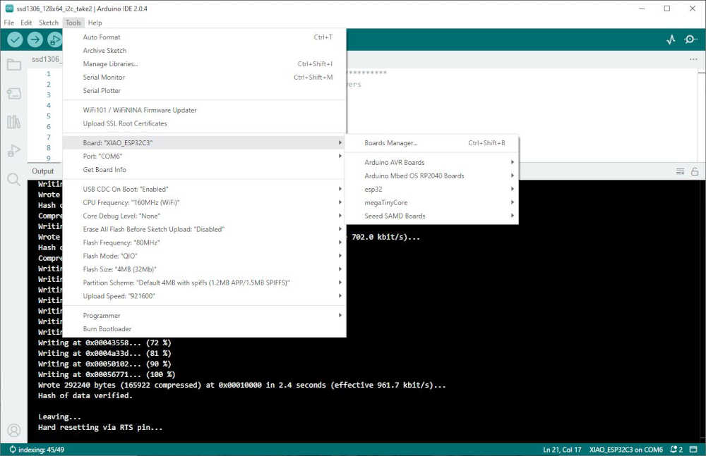
Another iteration with XIAO ESP32C3 and back to Windows > First, I made sure the blinkesp32.ino would compile and upload when I was using XIAO_ESP32C3 from the Board Manager through the esp32 by Espressif Systems package. I had to change the LED pin to D10 since it is different than the XIAO RP2040, that is pin 3 for the same pin… Thanks again Adrian!!! Following the tutorial I was instructed to use the SSD1306 library from Adafruit. After installing the library it provided me the ssd1306_demo.ino as the author used from the Adafruit SSD1306 selection. I made sure the port was connected and the XIAO_ESP32C3 board was selected, then I compiled and uploaded this program. The output looked good in the Arduino IDE, but I did not get the display I was expecting; in other words, I got nothing :) However, as I was compiling and uploading…in the back of my mind I remembered the oled address that I searched for in a previous iteration. This is the line I went to in the code:
#define SCREEN_ADDRESS 0x3D ///< See datasheet for Address; 0x3D for 128x64, 0x3C for 128x32
From experience I know that 0x3D needs to be 0x3C, so I changed it, saved it, compiled it, uploaded it (after checking my port connection), and voila!, I have output on the OLED :) Now that was a lot of work to make sure that my design was going to work; even though I haven’t designed it yet. All of that was done on a breadboard, and I am so glad I didn’t try to design it first.
Sketch uses 276088 bytes (21%) of program storage space. Maximum is 1310720 bytes.
Global variables use 16292 bytes (4%) of dynamic memory, leaving 311388 bytes for local variables. Maximum is 327680 bytes.
esptool.py v4.5.1
Serial port COM6
Connecting...
Chip is ESP32-C3 (revision v0.4)
Features: WiFi, BLE
Crystal is 40MHz
MAC: 34:85:18:03:58:f8
Uploading stub...
Running stub...
Stub running...
Changing baud rate to 921600
Changed.
Configuring flash size...
Flash will be erased from 0x00000000 to 0x00003fff...
Flash will be erased from 0x00008000 to 0x00008fff...
Flash will be erased from 0x0000e000 to 0x0000ffff...
Flash will be erased from 0x00010000 to 0x00057fff...
Compressed 13152 bytes to 9473...
Writing at 0x00000000... (100 %)
Wrote 13152 bytes (9473 compressed) at 0x00000000 in 0.2 seconds (effective 476.0 kbit/s)...
Hash of data verified.
Compressed 3072 bytes to 146...
Writing at 0x00008000... (100 %)
Wrote 3072 bytes (146 compressed) at 0x00008000 in 0.0 seconds (effective 535.9 kbit/s)...
Hash of data verified.
Compressed 8192 bytes to 47...
Writing at 0x0000e000... (100 %)
Wrote 8192 bytes (47 compressed) at 0x0000e000 in 0.1 seconds (effective 702.0 kbit/s)...
Hash of data verified.
Compressed 292240 bytes to 165922...
Writing at 0x00010000... (9 %)
Writing at 0x0001a871... (18 %)
Writing at 0x00022c72... (27 %)
Writing at 0x00029b15... (36 %)
Writing at 0x0002faf7... (45 %)
Writing at 0x00035d6b... (54 %)
Writing at 0x0003ba44... (63 %)
Writing at 0x00043558... (72 %)
Writing at 0x0004a33d... (81 %)
Writing at 0x00050102... (90 %)
Writing at 0x00056771... (100 %)
Wrote 292240 bytes (165922 compressed) at 0x00010000 in 2.4 seconds (effective 961.7 kbit/s)...
Hash of data verified.

Leaving...
Hard resetting via RTS pin...
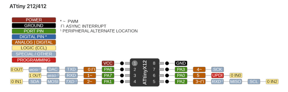
One last thing to check is how to display using an OLED from an attiny412… I search for assistance and found help from Edward Faako where I found the pins I need to use SCK and SDA for the OLED pins. I will also be using the GND and 3V3 pins. Thank you, Edward!
So I removed the OLED from my XIAO-ESP32-C3 breadboard and mounted it on the attiny412 breadboard. I thought I would give the OLED demo code a try to see if it would work as is. Since I am using UPDI to program, I shifted to Arduino IDE 1.18.19 since this was the process I used to program the attiny412 for the hello.t412.blink.ino provided by Neil. Thank you, Neil! The Arduino IDE attempted to compile, but I had an error:
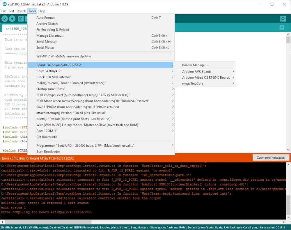
Arduino: 1.8.19 (Windows 10), Board: "ATtiny412/402/212/202, ATtiny412, 20 MHz internal, 1.8V (5 MHz or less), Disabled/Disabled, EEPROM retained, Enabled (default timer), 8ms, Master or Slave (saves flash and RAM), Default (doesn't print floats, 1.4k flash use), On all pins, like usual"

C:\Users\pneum\Documents\Arduino\libraries\Adafruit_SSD1306\Adafruit_SSD1306.cpp: In member function 'void Adafruit_SSD1306::ssd1306_commandList(const uint8_t*, uint8_t)':

C:\Users\pneum\Documents\Arduino\libraries\Adafruit_SSD1306\Adafruit_SSD1306.cpp:422:20: warning: comparison between signed and unsigned integer expressions [-Wsign-compare]

       if (bytesOut >= WIRE_MAX) {

C:\Users\pneum\Documents\Arduino\libraries\Adafruit_SSD1306\Adafruit_SSD1306.cpp: In member function 'void Adafruit_SSD1306::display()':

C:\Users\pneum\Documents\Arduino\libraries\Adafruit_SSD1306\Adafruit_SSD1306.cpp:1018:20: warning: comparison between signed and unsigned integer expressions [-Wsign-compare]

       if (bytesOut >= WIRE_MAX) {

c:/users/pneum/appdata/local/arduino15/packages/dxcore/tools/avr-gcc/7.3.0-atmel3.6.1-azduino4b/bin/../lib/gcc/avr/7.3.0/../../../../avr/bin/ld.exe: address 0x4da8 of C:\Users\pneum\AppData\Local\Temp\arduino_build_188413/ssd1306_128x64_i2c_take2.ino.elf section `.text' is not within region `text'

c:/users/pneum/appdata/local/arduino15/packages/dxcore/tools/avr-gcc/7.3.0-atmel3.6.1-azduino4b/bin/../lib/gcc/avr/7.3.0/../../../../avr/bin/ld.exe: C:\Users\pneum\AppData\Local\Temp\arduino_build_188413/ssd1306_128x64_i2c_take2.ino.elf section `.rodata' will not fit in region `text'

c:/users/pneum/appdata/local/arduino15/packages/dxcore/tools/avr-gcc/7.3.0-atmel3.6.1-azduino4b/bin/../lib/gcc/avr/7.3.0/../../../../avr/bin/ld.exe: address 0x4da8 of C:\Users\pneum\AppData\Local\Temp\arduino_build_188413/ssd1306_128x64_i2c_take2.ino.elf section `.text' is not within region `text'

c:/users/pneum/appdata/local/arduino15/packages/dxcore/tools/avr-gcc/7.3.0-atmel3.6.1-azduino4b/bin/../lib/gcc/avr/7.3.0/../../../../avr/bin/ld.exe: region `text' overflowed by 15919 bytes

c:/users/pneum/appdata/local/arduino15/packages/dxcore/tools/avr-gcc/7.3.0-atmel3.6.1-azduino4b/bin/../lib/gcc/avr/7.3.0/../../../../avr/lib/avrxmega3/short-calls/crtattiny412.o: In function `__vectors':

../../../../../crt1/gcrt1.S:80:(.vectors+0x1c): relocation truncated to fit: R_AVR_13_PCREL against symbol `__vector_14' defined in .text section in C:\Users\pneum\AppData\Local\Temp\ccxHhbge.ltrans0.ltrans.o

../../../../../crt1/gcrt1.S:85:(.vectors+0x26): relocation truncated to fit: R_AVR_13_PCREL against symbol `__vector_19' defined in .text section in C:\Users\pneum\AppData\Local\Temp\ccxHhbge.ltrans0.ltrans.o

../../../../../crt1/gcrt1.S:88:(.vectors+0x2c): relocation truncated to fit: R_AVR_13_PCREL against symbol `__vector_22' defined in .text section in C:\Users\pneum\AppData\Local\Temp\ccxHhbge.ltrans0.ltrans.o

../../../../../crt1/gcrt1.S:89:(.vectors+0x2e): relocation truncated to fit: R_AVR_13_PCREL against symbol `__vector_23' defined in .text section in C:\Users\pneum\AppData\Local\Temp\ccxHhbge.ltrans0.ltrans.o

../../../../../crt1/gcrt1.S:90:(.vectors+0x30): relocation truncated to fit: R_AVR_13_PCREL against symbol `__vector_24' defined in .text section in C:\Users\pneum\AppData\Local\Temp\ccxHhbge.ltrans0.ltrans.o

c:/users/pneum/appdata/local/arduino15/packages/dxcore/tools/avr-gcc/7.3.0-atmel3.6.1-azduino4b/bin/../lib/gcc/avr/7.3.0/../../../../avr/lib/avrxmega3/short-calls/crtattiny412.o:../../../../../crt1/gcrt1.S:314:(.init9+0x0): relocation truncated to fit: R_AVR_13_PCREL against symbol `main' defined in .text.startup section in C:\Users\pneum\AppData\Local\Temp\ccxHhbge.ltrans0.ltrans.o

c:/users/pneum/appdata/local/arduino15/packages/dxcore/tools/avr-gcc/7.3.0-atmel3.6.1-azduino4b/bin/../lib/gcc/avr/7.3.0/../../../../avr/lib/avrxmega3/short-calls/crtattiny412.o:../../../../../crt1/gcrt1.S:315:(.init9+0x2): relocation truncated to fit: R_AVR_13_PCREL against symbol `exit' defined in .fini9 section in c:/users/pneum/appdata/local/arduino15/packages/dxcore/tools/avr-gcc/7.3.0-atmel3.6.1-azduino4b/bin/../lib/gcc/avr/7.3.0/avrxmega3/short-calls\libgcc.a(_exit.o)

C:\Users\pneum\AppData\Local\Temp\ccxHhbge.ltrans0.ltrans.o: In function `UartClass::_poll_tx_data_empty()':

<artificial>:(.text+0xfc): relocation truncated to fit: R_AVR_13_PCREL against `no symbol'

C:\Users\pneum\AppData\Local\Temp\ccxHhbge.ltrans0.ltrans.o: In function `TWI_MasterSetBaud.part.3':

<artificial>:(.text+0x180a): relocation truncated to fit: R_AVR_13_PCREL against symbol `__udivmodsi4' defined in .text.libgcc.div section in c:/users/pneum/appdata/local/arduino15/packages/dxcore/tools/avr-gcc/7.3.0-atmel3.6.1-azduino4b/bin/../lib/gcc/avr/7.3.0/avrxmega3/short-calls\libgcc.a(_udivmodsi4.o)

C:\Users\pneum\AppData\Local\Temp\ccxHhbge.ltrans0.ltrans.o: In function `Adafruit_SSD1306::clearDisplay() [clone .constprop.40]':

<artificial>:(.text+0x1934): relocation truncated to fit: R_AVR_13_PCREL against symbol `memset' defined in .text.avr-libc section in c:/users/pneum/appdata/local/arduino15/packages/dxcore/tools/avr-gcc/7.3.0-atmel3.6.1-azduino4b/bin/../lib/gcc/avr/7.3.0/../../../../avr/lib/avrxmega3/short-calls\libc.a(memset.o)

C:\Users\pneum\AppData\Local\Temp\ccxHhbge.ltrans0.ltrans.o: In function `UartClass::begin(unsigned long, unsigned int)':

<artificial>:(.text+0x1ab2): additional relocation overflows omitted from the output

collect2.exe: error: ld returned 1 exit status

exit status 1

Error compiling for board ATtiny412/402/212/202.


This report would have more information with
"Show verbose output during compilation"
option enabled in File -> Preferences.
I’m guessing the attiny412 doesn’t have the capacity to hold the software, but I found another student with a similar problem. So I hope to stand on the shoulders of a more learned giant. Thank you, Vincent! The code worked without any modification and I am so thankful! I think I’ll add this to the output devices group assignment above. It’s soooo nice when things work :)
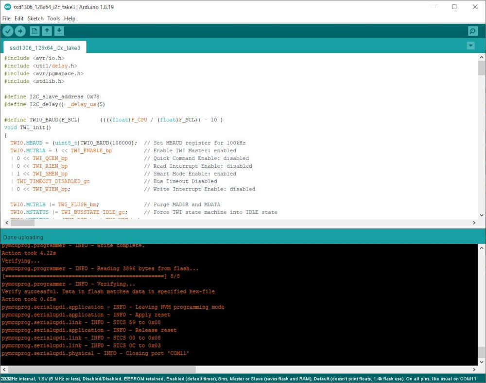
Sketch uses 3896 bytes (95%) of program storage space. Maximum is 4096 bytes.
Global variables use 28 bytes (10%) of dynamic memory, leaving 228 bytes for local variables. Maximum is 256 bytes.
C:\Users\pneum\AppData\Local\Arduino15\packages\megaTinyCore\tools\python3\3.7.2-post1/python3 -u C:\Users\pneum\AppData\Local\Arduino15\packages\megaTinyCore\hardware\megaavr\2.5.11/tools/prog.py -t uart -u COM11 -b 230400 -d attiny412 --fuses 2:0x02 6:0x04 8:0x00 -fC:\Users\pneum\AppData\Local\Temp\arduino_build_577114/ssd1306_128x64_i2c_take3.ino.hex -a write -v
SerialUPDI
UPDI programming for Arduino using a serial adapter
Based on pymcuprog, with significant modifications
By Quentin Bolsee and Spence Konde
Version 1.2.3 - Jan 2022
Using serial port COM11 at 230400 baud.
Target: attiny412
Set fuses: ['2:0x02', '6:0x04', '8:0x00']
Action: write
File: C:\Users\pneum\AppData\Local\Temp\arduino_build_577114/ssd1306_128x64_i2c_take3.ino.hex
pymcuprog.programmer - INFO - Setting up programming session for 'attiny412'
pymcuprog.deviceinfo.deviceinfo - INFO - Looking for device attiny412
pymcuprog.serialupdi.physical - INFO - Opening port 'COM11' at '115200' baud
pymcuprog.serialupdi.link - INFO - STCS 08 to 0x03
pymcuprog.serialupdi.link - INFO - STCS 06 to 0x02
pymcuprog.serialupdi.link - INFO - LDCS from 0x00
pymcuprog.serialupdi.link - INFO - UPDI init OK
pymcuprog.serialupdi.link - INFO - STCS 06 to 0x02
pymcuprog.serialupdi.link - INFO - Setting UPDI clock to 8 MHz
pymcuprog.serialupdi.link - INFO - STCS 02 to 0x09
pymcuprog.serialupdi.physical - INFO - Switching to '230400' baud
pymcuprog.serialupdi.application - INFO - SIB: 'tinyAVR P:0D:0-3M2 (02.59B14.0)'
pymcuprog.serialupdi.application - INFO - Device family ID: 'tinyAVR'
pymcuprog.serialupdi.application - INFO - NVM interface: 'P:0'
pymcuprog.serialupdi.application - INFO - Debug interface: 'D:0'
pymcuprog.serialupdi.application - INFO - PDI oscillator: '3M2'
pymcuprog.serialupdi.application - INFO - Extra info: '(02.59B14.0)'
pymcuprog.serialupdi.application - INFO - Using 16-bit UPDI
pymcuprog.serialupdi.link - INFO - LDCS from 0x00
pymcuprog.serialupdi.application - INFO - PDI revision = 0x02
pymcuprog.serialupdi.link - INFO - LDCS from 0x0B
pymcuprog.serialupdi.link - INFO - LDCS from 0x0B
pymcuprog.serialupdi.application - INFO - Entering NVM programming mode
pymcuprog.serialupdi.link - INFO - LDCS from 0x07
pymcuprog.serialupdi.application - INFO - Apply reset
pymcuprog.serialupdi.link - INFO - STCS 59 to 0x08
pymcuprog.serialupdi.application - INFO - Release reset
pymcuprog.serialupdi.link - INFO - STCS 00 to 0x08
pymcuprog.serialupdi.link - INFO - LDCS from 0x0B
pymcuprog.serialupdi.link - INFO - LDCS from 0x0B
pymcuprog.nvm - INFO - No specific initializer for this provider
Pinging device...
pymcuprog.programmer - INFO - Reading device ID...
pymcuprog.serialupdi.application - INFO - SIB: 'tinyAVR P:0D:0-3M2 (02.59B14.0)'
pymcuprog.serialupdi.application - INFO - Device family ID: 'tinyAVR'
pymcuprog.serialupdi.application - INFO - NVM interface: 'P:0'
pymcuprog.serialupdi.application - INFO - Debug interface: 'D:0'
pymcuprog.serialupdi.application - INFO - PDI oscillator: '3M2'
pymcuprog.serialupdi.application - INFO - Extra info: '(02.59B14.0)'
pymcuprog.serialupdi.application - INFO - Using 16-bit UPDI
pymcuprog.serialupdi.link - INFO - LDCS from 0x00
pymcuprog.serialupdi.application - INFO - PDI revision = 0x02
pymcuprog.serialupdi.link - INFO - LDCS from 0x0B
pymcuprog.serialupdi.application - INFO - Device ID from pyupdi = '1E9223' rev 'C'
pymcuprog.nvm - INFO - Device ID: '1E9223'
pymcuprog.nvm - INFO - Device revision: 'C'
pymcuprog.nvm - INFO - Device serial number: 'b'304b444549308e571e22''
Ping response: 1E9223
Setting fuse 0x2=0x2
Writing literal values...
pymcuprog.programmer - INFO - Write...
pymcuprog.programmer - INFO - Writing 1 bytes of data to fuses...
pymcuprog.programmer - INFO - Write complete.
Verifying literal values...
pymcuprog.programmer - INFO - Reading 1 bytes from fuses...
pymcuprog.programmer - INFO - Verifying...
Action took 0.19s
Setting fuse 0x6=0x4
Writing literal values...
pymcuprog.programmer - INFO - Write...
pymcuprog.programmer - INFO - Writing 1 bytes of data to fuses...
pymcuprog.programmer - INFO - Write complete.
Verifying literal values...
pymcuprog.programmer - INFO - Reading 1 bytes from fuses...
pymcuprog.programmer - INFO - Verifying...
Action took 0.19s
Setting fuse 0x8=0x0
Writing literal values...
pymcuprog.programmer - INFO - Write...
pymcuprog.programmer - INFO - Writing 1 bytes of data to fuses...
pymcuprog.programmer - INFO - Write complete.
Verifying literal values...
pymcuprog.programmer - INFO - Reading 1 bytes from fuses...
pymcuprog.programmer - INFO - Verifying...
Action took 0.19s
Finished writing fuses.
Chip/Bulk erase,
Memory type eeprom is conditionally erased (depending upon EESAVE fuse setting)
Memory type flash is always erased
Memory type lockbits is always erased
...
pymcuprog.programmer - INFO - Erase...
pymcuprog.serialupdi.nvm - INFO - Chip erase using NVM CTRL
Erased.
Action took 0.06s
Writing from hex file...
Writing flash...
pymcuprog.programmer - INFO - Write...
pymcuprog.programmer - INFO - Writing 3896 bytes of data to flash...
[==================================================] 61/61
pymcuprog.programmer - INFO - Write complete.
Action took 4.22s
Verifying...
pymcuprog.programmer - INFO - Reading 3896 bytes from flash...
[==================================================] 8/8
pymcuprog.programmer - INFO - Verifying...
Verify successful. Data in flash matches data in specified hex-file
Action took 0.65s
pymcuprog.serialupdi.application - INFO - Leaving NVM programming mode
pymcuprog.serialupdi.application - INFO - Apply reset
pymcuprog.serialupdi.link - INFO - STCS 59 to 0x08
pymcuprog.serialupdi.application - INFO - Release reset
pymcuprog.serialupdi.link - INFO - STCS 00 to 0x08
pymcuprog.serialupdi.link - INFO - STCS 0C to 0x03
pymcuprog.serialupdi.physical - INFO - Closing port 'COM11'
Now onto designing…
Well almost… I wanted to try a known file that I will need for communicating from the FTDI to UPDI. Adrian provided the png files, so I will take them through Mods as I did before, using my instruction in my repo, to see how this turns out. It’s been a while :)
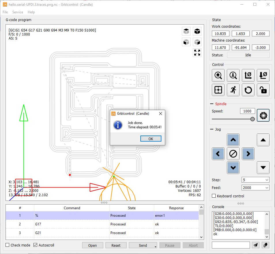
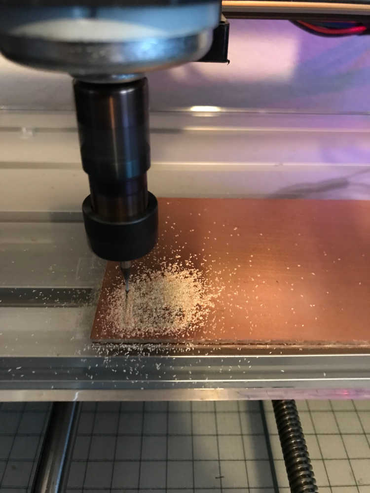
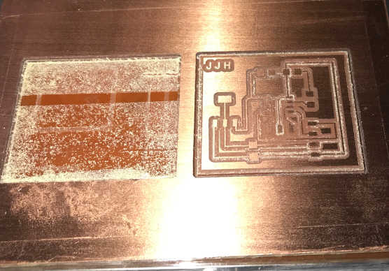
- I downloaded Adrian’s png files > imported them into mods > followed my instructions here under “Evidence of What Happened as a Continuing Student in Fab Academy 2022” > made the one line change in the g-code that I mentioned: It was line 15 “G04 P1000” changed to “G04 P1” (shorter wait :) > plugged in power to the Sweety > plugged in the USB cable > found the Candle software here: C:\Digital Fabrication_Candle3018\Grblcontrol(Candle_1.1.7 ) > ran Grblcontrol (Candle).exe > Loaded hello.serial-UPDI.3.traces.png.nc > Had two errors that I ignored due to experience from previous runs
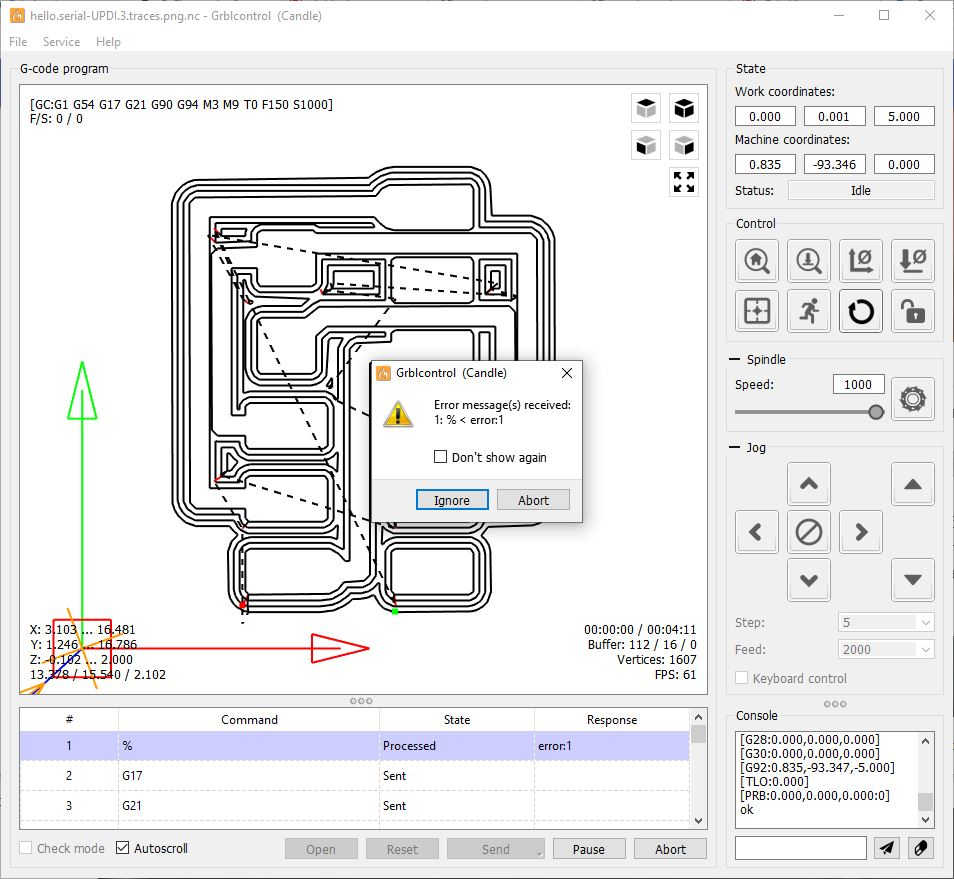
traces milled perfectly
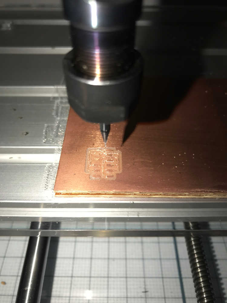
Loaded hello.serial-UPDI.3.interior.png.nc > ignored errors > interior milled perfectly, but the part came loose at the end
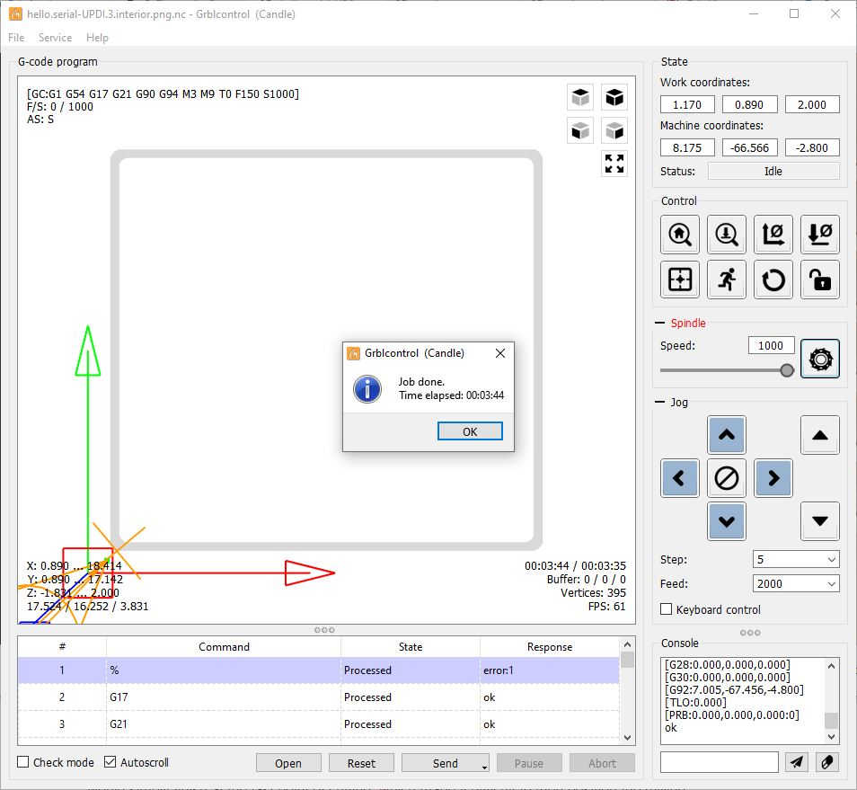
Thankfully there was no damage
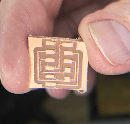
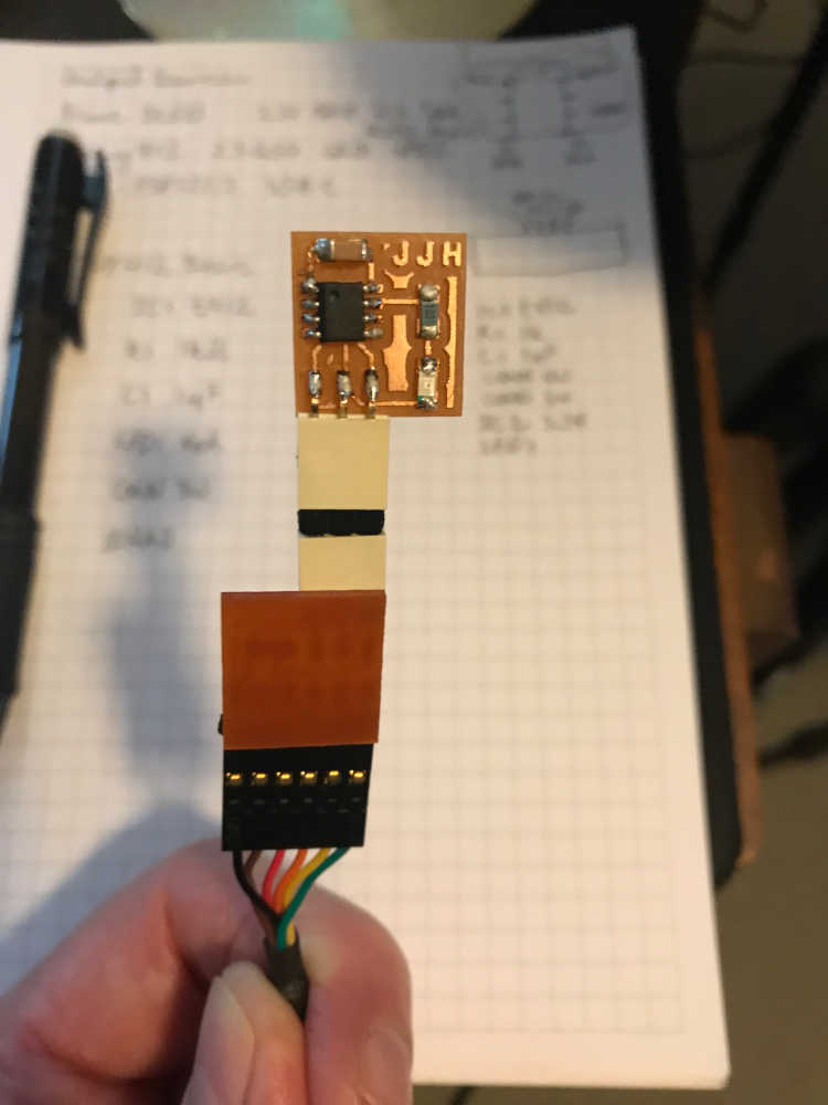
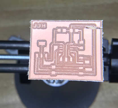
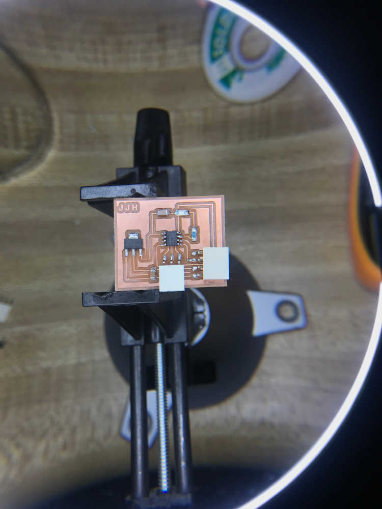
I deburred the part and washed it > Successfully milled the board > Unfortunately, when I was putting the UPDI connector on, one of the pads lifted away > I decided to mill another one rather than try to fix it > Milled another board, but ran out of time. This time I took a picture of the finished board.
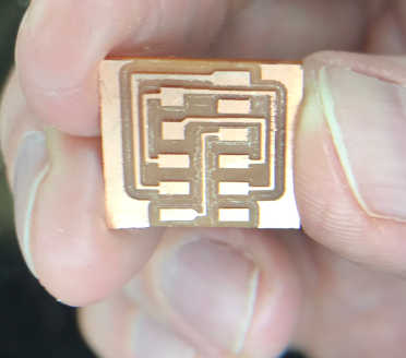
After class, I practiced with the soldering station to see if I could learn from my failure. First I looked up the recommended temperature for soldering and found that my temperature was to high at 450C; it should be 400C. I have 60/40 solder from 2000, so I tried it and it worked great at that temperature. However, I have the non-lead solder recommended in the inventory, so I thought I would try again. Turns out that it works great if you use a little flux paste, so I stuffed the serial-updi interface board.
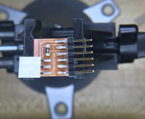
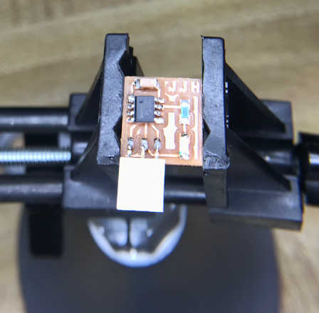
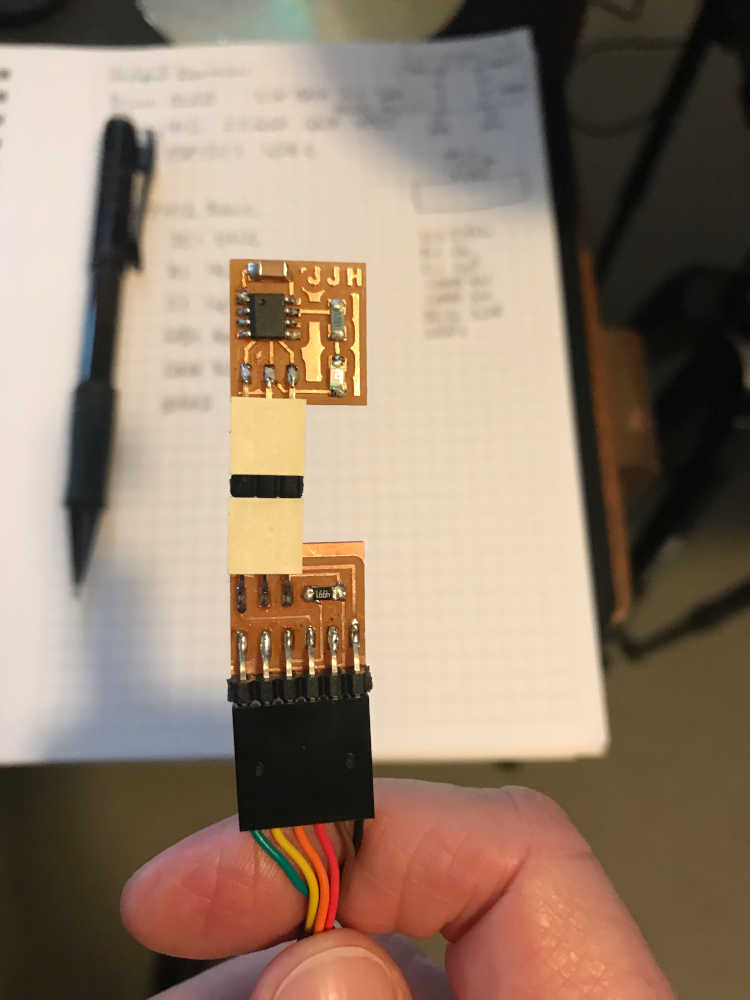
This is the serial-updi interface that I stuffed successfully:
Now to complete design!
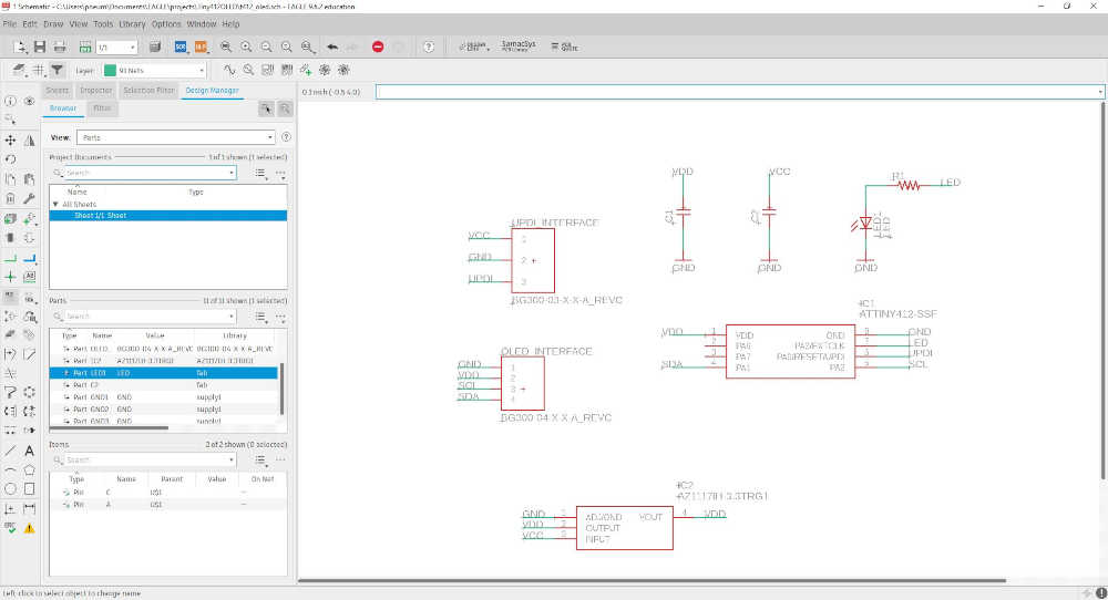
I did a major reboot in design. Although I began designing the attiny412 OLED board, I ran into difficulties with the routing of the wires in Eagle. I had already gone through the proof of concept on a breadboard and confirmed that the design worked. I retraced my steps, added all of the components to the library in Eagle. I designed the schematic and then the board. I could not get the wires to route to my satifaction, so now the “major reboot”: For starters, I have never completely understood the workflow in Eagle; I did go through the tutorial and added a switch and LED, but I never actually output the board to a png and milled it. My method of making it past that obstacle was using pcb.py and frep.py, redoing what Neil showed us in Electronics Production. I really preferred that workflow to Eagle because it made sense and I could do it. Once I finished, I never looked back; life happened and here I am, five years later, doing this again. However, this cycle, I have time to muscle through it. So here we go:
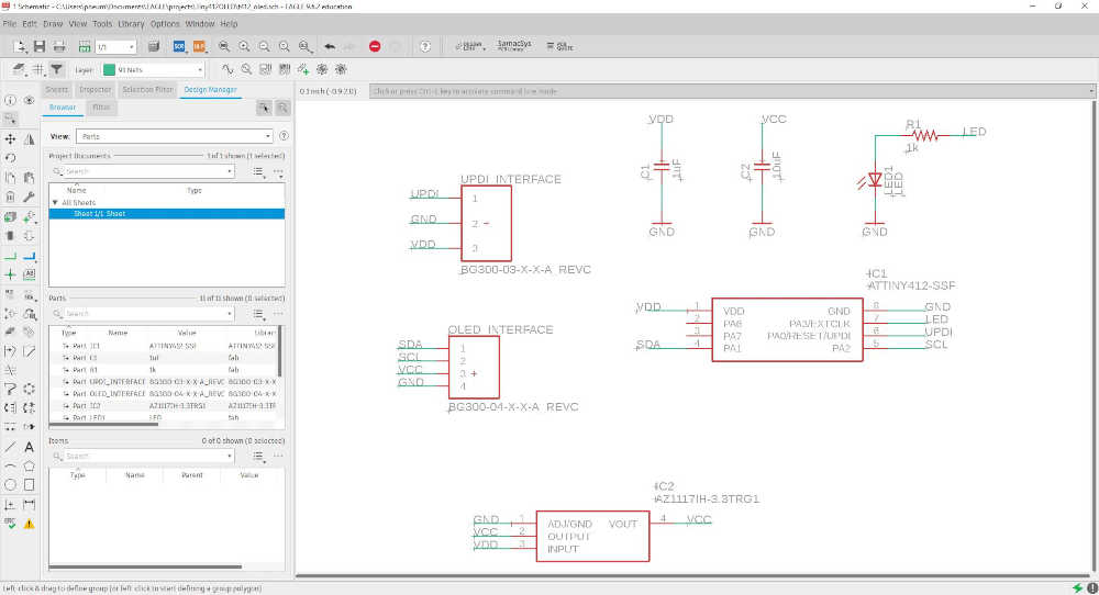
First, here is the schematic of the attiny412 OLED design concept as demonstrated with the breadboard prototype:
This is the rats nest that I abandoned after several attempts (it was getting late):
I got some rest and came back to it the next day. I decided to start at the beginning; just make the schematic and board for a basic attiny412 blinking the LED, so that’s what I set out to do. I looked at Neil’s hello.t412.3.blink.png and listed the components in my note book. Actually, I did that later, but this is probably the correct way to do it:
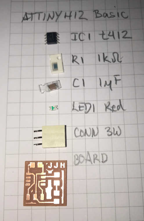
So how did I make that board! :) I’ll tell the story:
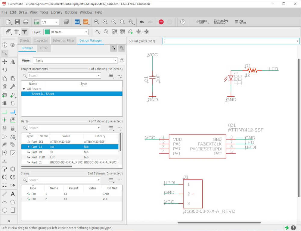
- With the list of parts, I went into Eagle made a new project and made sure the libraries were there. After making a new Schematic, I used ADD to add the parts in the Schematic Editor. Using Net, I added wires to each of the connections and used Name to interconnect all of the connections. After a lot of practice, it was a breeze. Once the schematic is done, you should use ERC under Tools to check for electrical errors. I had to add the values of the capacitor and resistor. Very helpful! Here is the result:
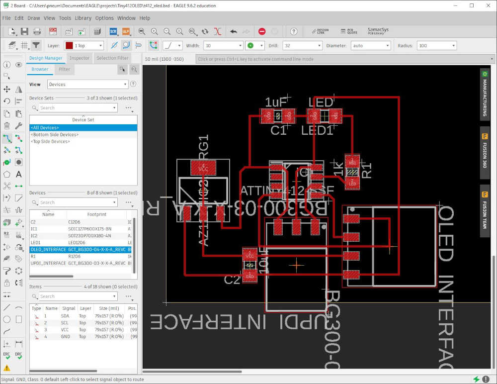
- I used the autoroute after I arranged the components in the same position Neil had them and the results weren’t too bad, but I did delete spme routes and fixed them. I also ran DRC under tools to check the Design Rules found in fab.dru. It actually turned out nicely:
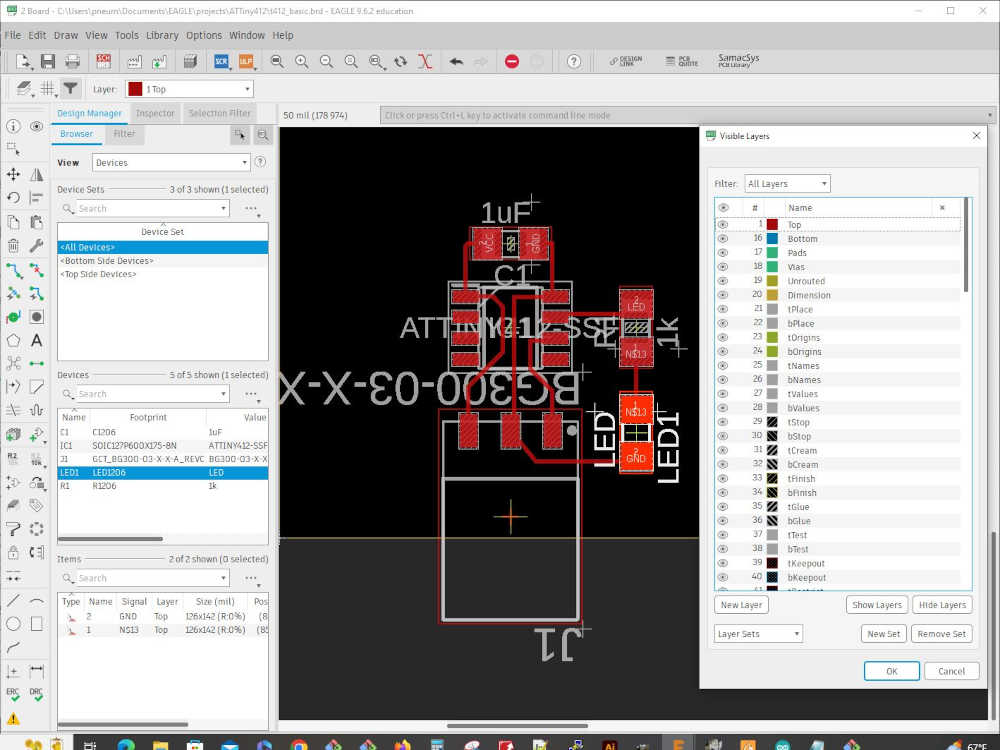
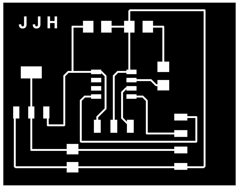
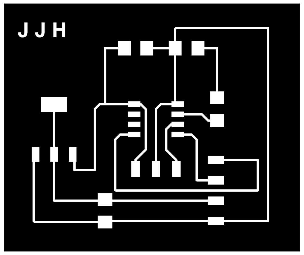
- This is the top layer after I finished the design:
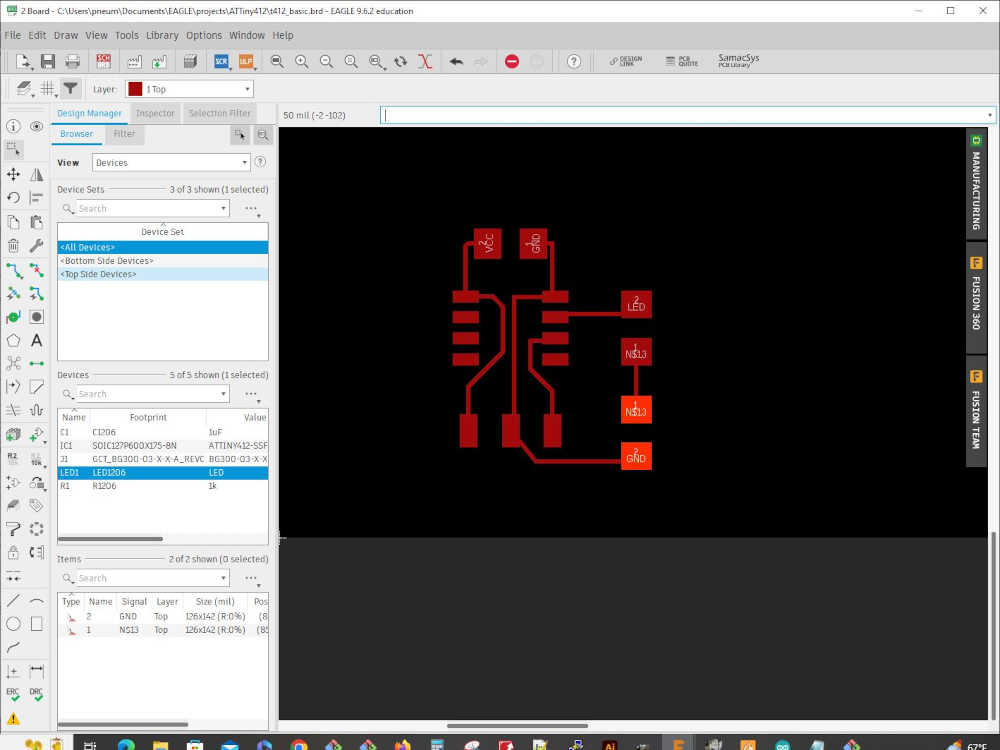
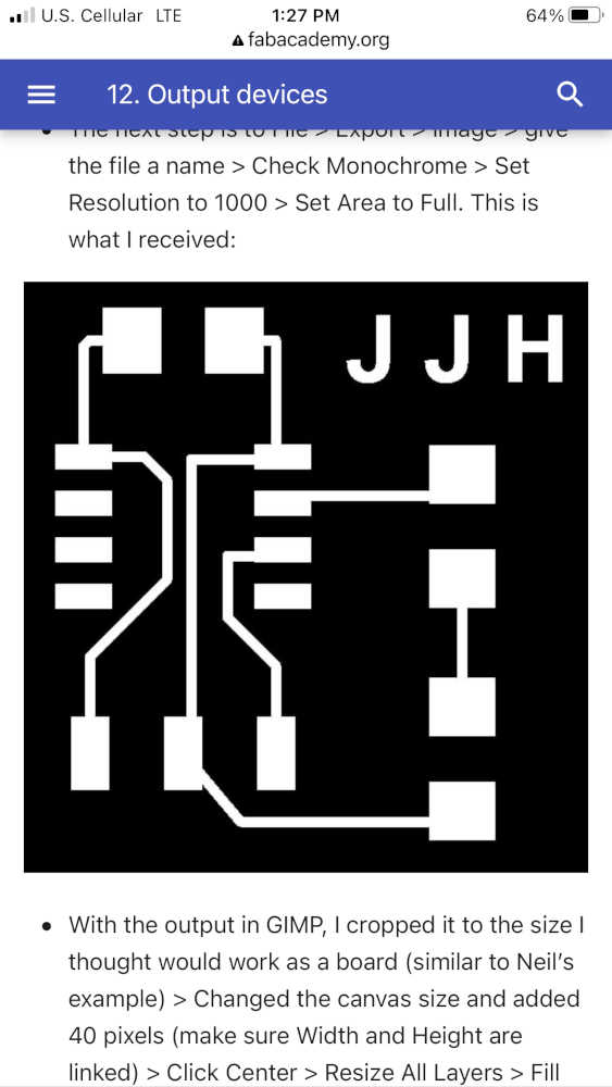
- The next step is to File > Export > Image > give the file a name > Check Monochrome > Set Resolution to 1000 > Set Area to Full. This is what I received:
- With the output in GIMP, I cropped it to the size I thought would work as a board (similar to Neil’s example) > Changed the canvas size and added 40 pixels (make sure Width and Height are linked) > Press the Tab key > Click Center > Resize All Layers > Fill with White > Click Resize > Export as a png file. This is the result (you can’t see the white border, but it has one):

- The next part was tricky and I can’t remember exactly how I got it to work, but basically, I made the center white and the border black. I’ll try again later and document it here. As promised: After you crop the output, it is better to Select All > Copy > File > New (this opens a new file with the dimensions of the copied image with a white background) > Don’t Paste the image > Just Change the canvas size as mentioned above, but fill the border with the foreground color instead of White (Make sure you center. Voila! You have a black frame around the white center. This is what you need for the png to bring into mods:

-
I used mods and brought the png files in and save the g-code as I did here
-
I milled the board very easily after so much practice with the serial-updi interface board :)
-
The board was stuffed:
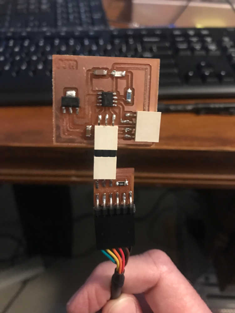
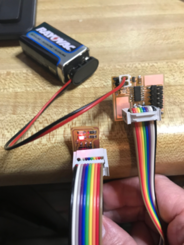
- The first attempt to program the board failed because I had the serial-updi interface reversed:
- The second attempt was successful using Neil’s blink.ino from embedded programming:
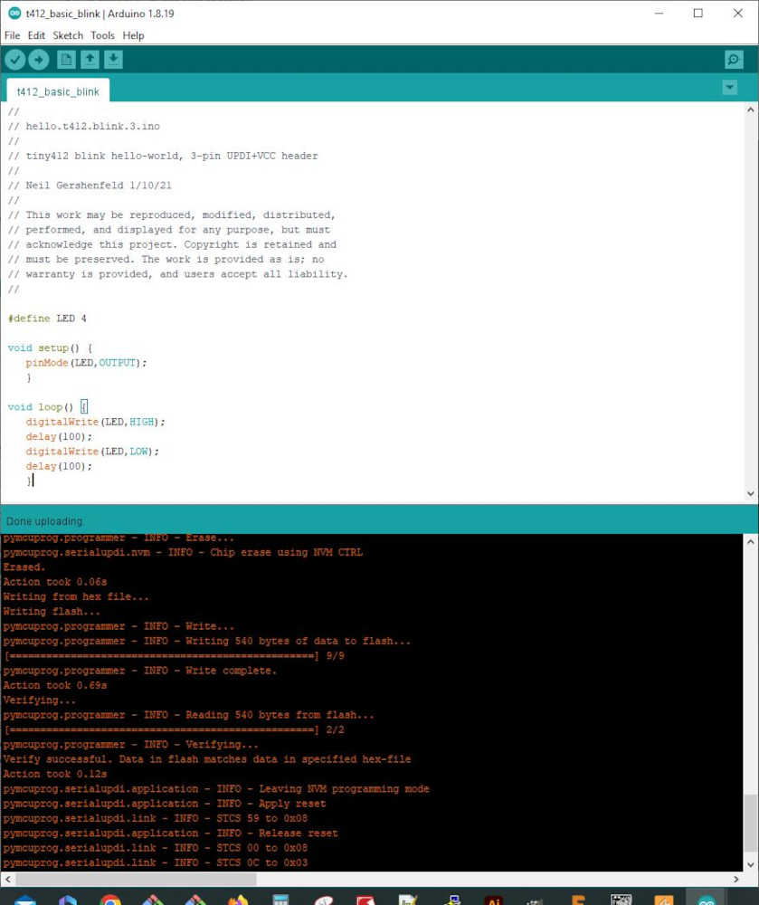
Sketch uses 540 bytes (13%) of program storage space. Maximum is 4096 bytes.
Global variables use 10 bytes (3%) of dynamic memory, leaving 246 bytes for local variables. Maximum is 256 bytes.
C:\Users\pneum\AppData\Local\Arduino15\packages\megaTinyCore\tools\python3\3.7.2-post1/python3 -u C:\Users\pneum\AppData\Local\Arduino15\packages\megaTinyCore\hardware\megaavr\2.5.11/tools/prog.py -t uart -u COM11 -b 230400 -d attiny412 --fuses 2:0x02 6:0x04 8:0x00 -fC:\Users\pneum\AppData\Local\Temp\arduino_build_20051/t412_basic_blink.ino.hex -a write -v
SerialUPDI
UPDI programming for Arduino using a serial adapter
Based on pymcuprog, with significant modifications
By Quentin Bolsee and Spence Konde
Version 1.2.3 - Jan 2022
Using serial port COM11 at 230400 baud.
Target: attiny412
Set fuses: ['2:0x02', '6:0x04', '8:0x00']
Action: write
File: C:\Users\pneum\AppData\Local\Temp\arduino_build_20051/t412_basic_blink.ino.hex
pymcuprog.programmer - INFO - Setting up programming session for 'attiny412'
pymcuprog.deviceinfo.deviceinfo - INFO - Looking for device attiny412
pymcuprog.serialupdi.physical - INFO - Opening port 'COM11' at '115200' baud
pymcuprog.serialupdi.link - INFO - STCS 08 to 0x03
pymcuprog.serialupdi.link - INFO - STCS 06 to 0x02
pymcuprog.serialupdi.link - INFO - LDCS from 0x00
pymcuprog.serialupdi.link - INFO - UPDI init OK
pymcuprog.serialupdi.link - INFO - STCS 06 to 0x02
pymcuprog.serialupdi.link - INFO - Setting UPDI clock to 8 MHz
pymcuprog.serialupdi.link - INFO - STCS 02 to 0x09
pymcuprog.serialupdi.physical - INFO - Switching to '230400' baud
pymcuprog.serialupdi.application - INFO - SIB: 'tinyAVR P:0D:0-3M2 (02.59B14.0)'
pymcuprog.serialupdi.application - INFO - Device family ID: 'tinyAVR'
pymcuprog.serialupdi.application - INFO - NVM interface: 'P:0'
pymcuprog.serialupdi.application - INFO - Debug interface: 'D:0'
pymcuprog.serialupdi.application - INFO - PDI oscillator: '3M2'
pymcuprog.serialupdi.application - INFO - Extra info: '(02.59B14.0)'
pymcuprog.serialupdi.application - INFO - Using 16-bit UPDI
pymcuprog.serialupdi.link - INFO - LDCS from 0x00
pymcuprog.serialupdi.application - INFO - PDI revision = 0x02
pymcuprog.serialupdi.link - INFO - LDCS from 0x0B
pymcuprog.serialupdi.link - INFO - LDCS from 0x0B
pymcuprog.serialupdi.application - INFO - Entering NVM programming mode
pymcuprog.serialupdi.link - INFO - LDCS from 0x07
pymcuprog.serialupdi.application - INFO - Apply reset
pymcuprog.serialupdi.link - INFO - STCS 59 to 0x08
pymcuprog.serialupdi.application - INFO - Release reset
pymcuprog.serialupdi.link - INFO - STCS 00 to 0x08
pymcuprog.serialupdi.link - INFO - LDCS from 0x0B
pymcuprog.serialupdi.link - INFO - LDCS from 0x0B
pymcuprog.serialupdi.link - INFO - LDCS from 0x0B
pymcuprog.serialupdi.link - INFO - LDCS from 0x0B
pymcuprog.serialupdi.link - INFO - LDCS from 0x0B
pymcuprog.nvm - INFO - No specific initializer for this provider
Pinging device...
pymcuprog.programmer - INFO - Reading device ID...
pymcuprog.serialupdi.application - INFO - SIB: 'tinyAVR P:0D:0-3M2 (02.59B14.0)'
pymcuprog.serialupdi.application - INFO - Device family ID: 'tinyAVR'
pymcuprog.serialupdi.application - INFO - NVM interface: 'P:0'
pymcuprog.serialupdi.application - INFO - Debug interface: 'D:0'
pymcuprog.serialupdi.application - INFO - PDI oscillator: '3M2'
pymcuprog.serialupdi.application - INFO - Extra info: '(02.59B14.0)'
pymcuprog.serialupdi.application - INFO - Using 16-bit UPDI
pymcuprog.serialupdi.link - INFO - LDCS from 0x00
pymcuprog.serialupdi.application - INFO - PDI revision = 0x02
pymcuprog.serialupdi.link - INFO - LDCS from 0x0B
pymcuprog.serialupdi.application - INFO - Device ID from pyupdi = '1E9223' rev 'C'
pymcuprog.nvm - INFO - Device ID: '1E9223'
pymcuprog.nvm - INFO - Device revision: 'C'
pymcuprog.nvm - INFO - Device serial number: 'b'304b444549304eb70231''
Ping response: 1E9223
Setting fuse 0x2=0x2
Writing literal values...
pymcuprog.programmer - INFO - Write...
pymcuprog.programmer - INFO - Writing 1 bytes of data to fuses...
pymcuprog.programmer - INFO - Write complete.
Verifying literal values...
pymcuprog.programmer - INFO - Reading 1 bytes from fuses...
pymcuprog.programmer - INFO - Verifying...
Action took 0.19s
Setting fuse 0x6=0x4
Writing literal values...
pymcuprog.programmer - INFO - Write...
pymcuprog.programmer - INFO - Writing 1 bytes of data to fuses...
pymcuprog.programmer - INFO - Write complete.
Verifying literal values...
pymcuprog.programmer - INFO - Reading 1 bytes from fuses...
pymcuprog.programmer - INFO - Verifying...
Action took 0.19s
Setting fuse 0x8=0x0
Writing literal values...
pymcuprog.programmer - INFO - Write...
pymcuprog.programmer - INFO - Writing 1 bytes of data to fuses...
pymcuprog.programmer - INFO - Write complete.
Verifying literal values...
pymcuprog.programmer - INFO - Reading 1 bytes from fuses...
pymcuprog.programmer - INFO - Verifying...
Action took 0.19s
Finished writing fuses.
Chip/Bulk erase,
Memory type eeprom is conditionally erased (depending upon EESAVE fuse setting)
Memory type flash is always erased
Memory type lockbits is always erased
...
pymcuprog.programmer - INFO - Erase...
pymcuprog.serialupdi.nvm - INFO - Chip erase using NVM CTRL
Erased.
Action took 0.06s
Writing from hex file...
Writing flash...
pymcuprog.programmer - INFO - Write...
pymcuprog.programmer - INFO - Writing 540 bytes of data to flash...
[==================================================] 9/9
pymcuprog.programmer - INFO - Write complete.
Action took 0.69s
Verifying...
pymcuprog.programmer - INFO - Reading 540 bytes from flash...
[==================================================] 2/2
pymcuprog.programmer - INFO - Verifying...
Verify successful. Data in flash matches data in specified hex-file
Action took 0.12s
pymcuprog.serialupdi.application - INFO - Leaving NVM programming mode
pymcuprog.serialupdi.application - INFO - Apply reset
pymcuprog.serialupdi.link - INFO - STCS 59 to 0x08
pymcuprog.serialupdi.application - INFO - Release reset
pymcuprog.serialupdi.link - INFO - STCS 00 to 0x08
pymcuprog.serialupdi.link - INFO - STCS 0C to 0x03
pymcuprog.serialupdi.physical - INFO - Closing port 'COM11'
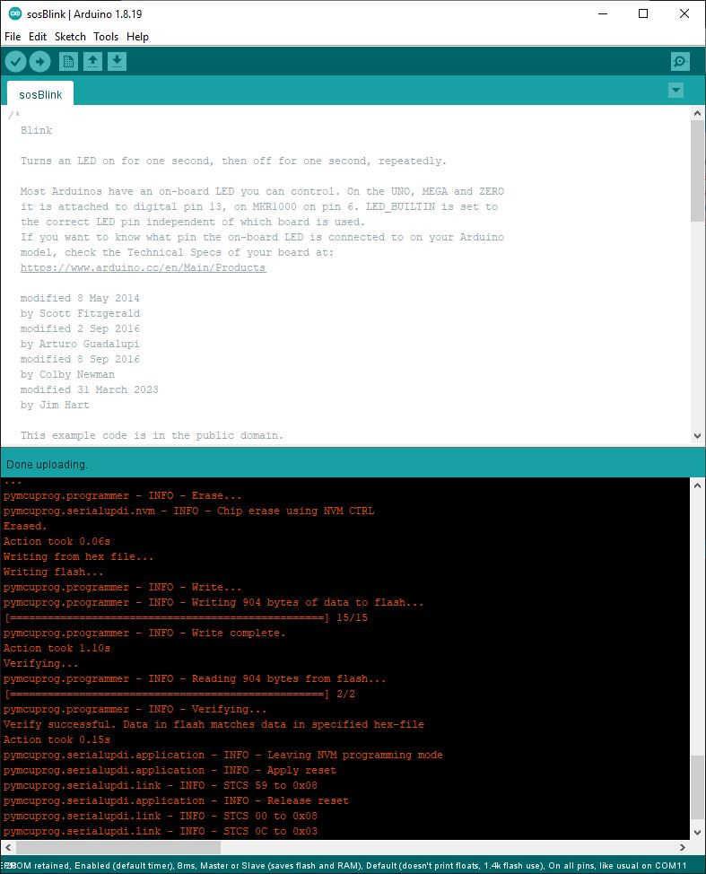
- The third attempt was successful using the Arduino Blink Example after modifying for S-O-S signal:
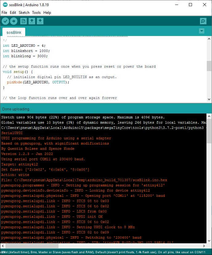
Sketch uses 904 bytes (22%) of program storage space. Maximum is 4096 bytes.
Global variables use 10 bytes (3%) of dynamic memory, leaving 246 bytes for local variables. Maximum is 256 bytes.
C:\Users\pneum\AppData\Local\Arduino15\packages\megaTinyCore\tools\python3\3.7.2-post1/python3 -u C:\Users\pneum\AppData\Local\Arduino15\packages\megaTinyCore\hardware\megaavr\2.5.11/tools/prog.py -t uart -u COM11 -b 230400 -d attiny412 --fuses 2:0x02 6:0x04 8:0x00 -fC:\Users\pneum\AppData\Local\Temp\arduino_build_701307/sosBlink.ino.hex -a write -v
SerialUPDI
UPDI programming for Arduino using a serial adapter
Based on pymcuprog, with significant modifications
By Quentin Bolsee and Spence Konde
Version 1.2.3 - Jan 2022
Using serial port COM11 at 230400 baud.
Target: attiny412
Set fuses: ['2:0x02', '6:0x04', '8:0x00']
Action: write
File: C:\Users\pneum\AppData\Local\Temp\arduino_build_701307/sosBlink.ino.hex
pymcuprog.programmer - INFO - Setting up programming session for 'attiny412'
pymcuprog.deviceinfo.deviceinfo - INFO - Looking for device attiny412
pymcuprog.serialupdi.physical - INFO - Opening port 'COM11' at '115200' baud
pymcuprog.serialupdi.link - INFO - STCS 08 to 0x03
pymcuprog.serialupdi.link - INFO - STCS 06 to 0x02
pymcuprog.serialupdi.link - INFO - LDCS from 0x00
pymcuprog.serialupdi.link - INFO - UPDI init OK
pymcuprog.serialupdi.link - INFO - STCS 06 to 0x02
pymcuprog.serialupdi.link - INFO - Setting UPDI clock to 8 MHz
pymcuprog.serialupdi.link - INFO - STCS 02 to 0x09
pymcuprog.serialupdi.physical - INFO - Switching to '230400' baud
pymcuprog.serialupdi.application - INFO - SIB: 'tinyAVR P:0D:0-3M2 (02.59B14.0)'
pymcuprog.serialupdi.application - INFO - Device family ID: 'tinyAVR'
pymcuprog.serialupdi.application - INFO - NVM interface: 'P:0'
pymcuprog.serialupdi.application - INFO - Debug interface: 'D:0'
pymcuprog.serialupdi.application - INFO - PDI oscillator: '3M2'
pymcuprog.serialupdi.application - INFO - Extra info: '(02.59B14.0)'
pymcuprog.serialupdi.application - INFO - Using 16-bit UPDI
pymcuprog.serialupdi.link - INFO - LDCS from 0x00
pymcuprog.serialupdi.application - INFO - PDI revision = 0x02
pymcuprog.serialupdi.link - INFO - LDCS from 0x0B
pymcuprog.serialupdi.link - INFO - LDCS from 0x0B
pymcuprog.serialupdi.application - INFO - Entering NVM programming mode
pymcuprog.serialupdi.link - INFO - LDCS from 0x07
pymcuprog.serialupdi.application - INFO - Apply reset
pymcuprog.serialupdi.link - INFO - STCS 59 to 0x08
pymcuprog.serialupdi.application - INFO - Release reset
pymcuprog.serialupdi.link - INFO - STCS 00 to 0x08
pymcuprog.serialupdi.link - INFO - LDCS from 0x0B
pymcuprog.serialupdi.link - INFO - LDCS from 0x0B
pymcuprog.nvm - INFO - No specific initializer for this provider
Pinging device...
pymcuprog.programmer - INFO - Reading device ID...
pymcuprog.serialupdi.application - INFO - SIB: 'tinyAVR P:0D:0-3M2 (02.59B14.0)'
pymcuprog.serialupdi.application - INFO - Device family ID: 'tinyAVR'
pymcuprog.serialupdi.application - INFO - NVM interface: 'P:0'
pymcuprog.serialupdi.application - INFO - Debug interface: 'D:0'
pymcuprog.serialupdi.application - INFO - PDI oscillator: '3M2'
pymcuprog.serialupdi.application - INFO - Extra info: '(02.59B14.0)'
pymcuprog.serialupdi.application - INFO - Using 16-bit UPDI
pymcuprog.serialupdi.link - INFO - LDCS from 0x00
pymcuprog.serialupdi.application - INFO - PDI revision = 0x02
pymcuprog.serialupdi.link - INFO - LDCS from 0x0B
pymcuprog.serialupdi.application - INFO - Device ID from pyupdi = '1E9223' rev 'C'
pymcuprog.nvm - INFO - Device ID: '1E9223'
pymcuprog.nvm - INFO - Device revision: 'C'
pymcuprog.nvm - INFO - Device serial number: 'b'304b444549304eb70231''
Ping response: 1E9223
Setting fuse 0x2=0x2
Writing literal values...
pymcuprog.programmer - INFO - Write...
pymcuprog.programmer - INFO - Writing 1 bytes of data to fuses...
pymcuprog.programmer - INFO - Write complete.
Verifying literal values...
pymcuprog.programmer - INFO - Reading 1 bytes from fuses...
pymcuprog.programmer - INFO - Verifying...
Action took 0.19s
Setting fuse 0x6=0x4
Writing literal values...
pymcuprog.programmer - INFO - Write...
pymcuprog.programmer - INFO - Writing 1 bytes of data to fuses...
pymcuprog.programmer - INFO - Write complete.
Verifying literal values...
pymcuprog.programmer - INFO - Reading 1 bytes from fuses...
pymcuprog.programmer - INFO - Verifying...
Action took 0.19s
Setting fuse 0x8=0x0
Writing literal values...
pymcuprog.programmer - INFO - Write...
pymcuprog.programmer - INFO - Writing 1 bytes of data to fuses...
pymcuprog.programmer - INFO - Write complete.
Verifying literal values...
pymcuprog.programmer - INFO - Reading 1 bytes from fuses...
pymcuprog.programmer - INFO - Verifying...
Action took 0.19s
Finished writing fuses.
Chip/Bulk erase,
Memory type eeprom is conditionally erased (depending upon EESAVE fuse setting)
Memory type flash is always erased
Memory type lockbits is always erased
...
pymcuprog.programmer - INFO - Erase...
pymcuprog.serialupdi.nvm - INFO - Chip erase using NVM CTRL
Erased.
Action took 0.06s
Writing from hex file...
Writing flash...
pymcuprog.programmer - INFO - Write...
pymcuprog.programmer - INFO - Writing 904 bytes of data to flash...
[==================================================] 15/15
pymcuprog.programmer - INFO - Write complete.
Action took 1.11s
Verifying...
pymcuprog.programmer - INFO - Reading 904 bytes from flash...
[==================================================] 2/2
pymcuprog.programmer - INFO - Verifying...
Verify successful. Data in flash matches data in specified hex-file
Action took 0.18s
pymcuprog.serialupdi.application - INFO - Leaving NVM programming mode
pymcuprog.serialupdi.application - INFO - Apply reset
pymcuprog.serialupdi.link - INFO - STCS 59 to 0x08
pymcuprog.serialupdi.application - INFO - Release reset
pymcuprog.serialupdi.link - INFO - STCS 00 to 0x08
pymcuprog.serialupdi.link - INFO - STCS 0C to 0x03
pymcuprog.serialupdi.physical - INFO - Closing port 'COM11'
Continuation of “Major Reboot”; in other words…Spiral Development! Below, you will see the video as my ‘hero shot’. At the time, I was feeling like a hero, but that was only the beginning. I thought I was done and updated my Nueval entry for Output Devices, but then I saw a FAQ entry at the bottom of the page, “Is it ok to use the LED in the hello board as an output device for this assignment?” and the “Answer: No, you need to do more.” Arghhhh! as in the Neil video. The message in my hero shot video is appropriate :)
Included a ‘hero shot’ of your board:
- Included a ‘hero shot’ of your board:
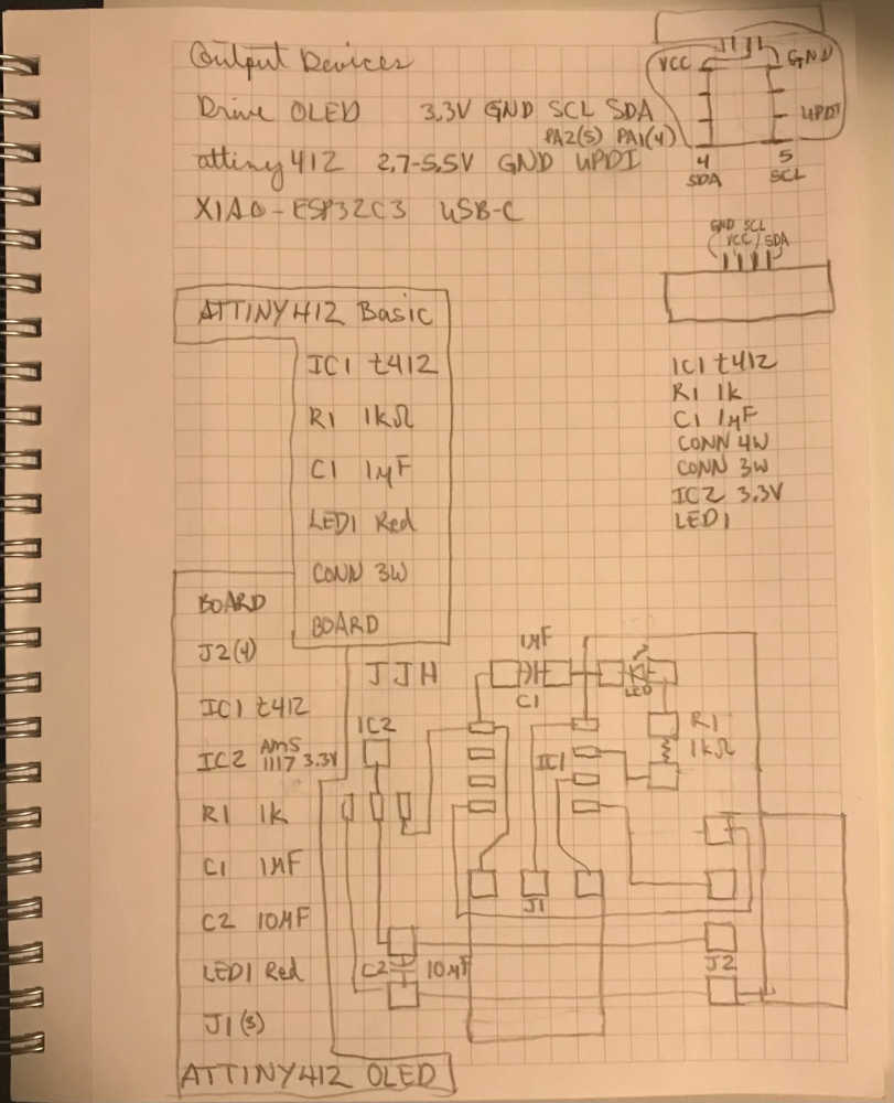
Not to worry! As a hero, you are never done; you must keep on keepin’ on! With my newly found and developed skills in Eagle, I shouldered up and got back on the task at hand. Since I already had the beginning of a solution in Eagle with the Tiny412OLED project (the one that intimidated me before), I opened it up to refresh my memory. All parts were in the schematic and the board was already built. I made a sketch in my notebook to figure out what needed to happen in order to make it work. At the time, my computer was unplugged due to the thunderstorms around and upon us, so I used my phone to display the png of the t412_basic_board that I had in my repo and took a screenshot:
Then I laid a piece of vellum paper on my phone and sketched the image:
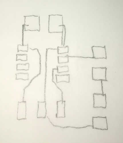
Using this, I transferred it to my notebook and made modifications to include the new parts for the schematic to determine how to wire it:
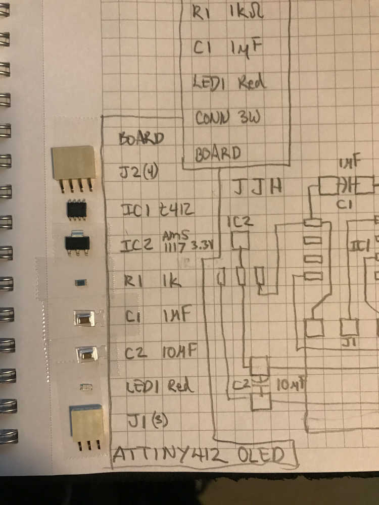
Then I gathered my materials:
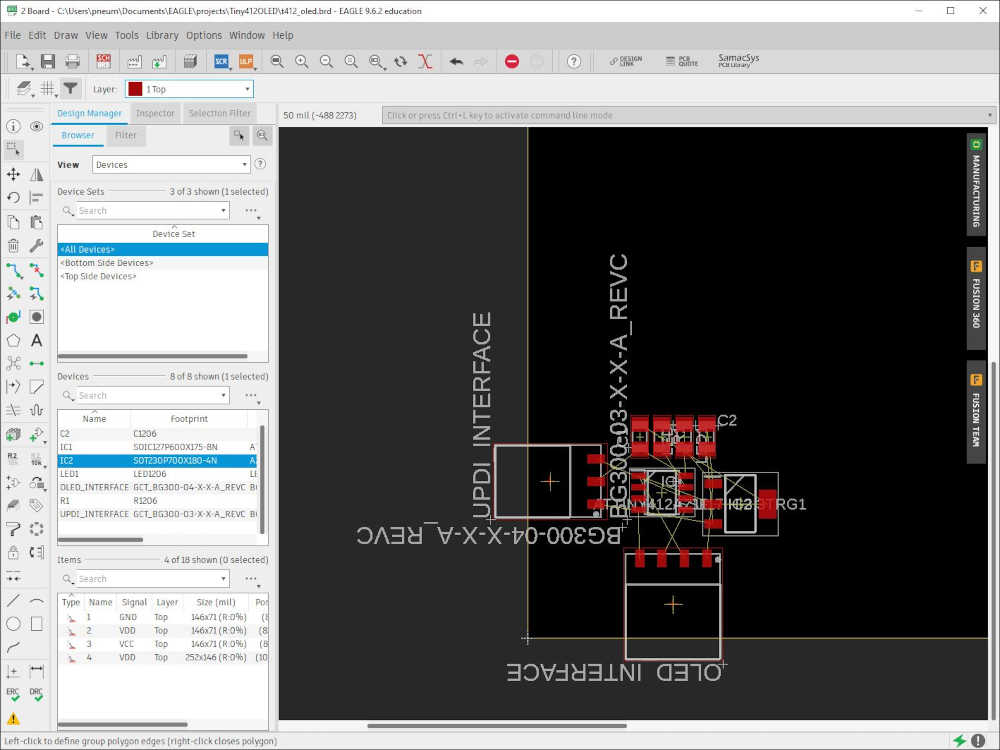
At this point, I looked at the schematic and there was very little to change. I ran the ERC and found that I left the values off of my discrete devices, so I added them and all was good. In the board, I had to move components around to get the wiring to work as I have in my sketch. It was much easier working from the sketch since I had already settled it in my mind; I used it as a guide. I didn’t mess with the airwires since it was already electrically correct. As I moved parts around, I saw my plan fall into place; it was a great feeling of accomplishment. A note to self: Always start with something simple and then expand it to the next level…Spiral Development! Well here is where I ended up after all the moves:
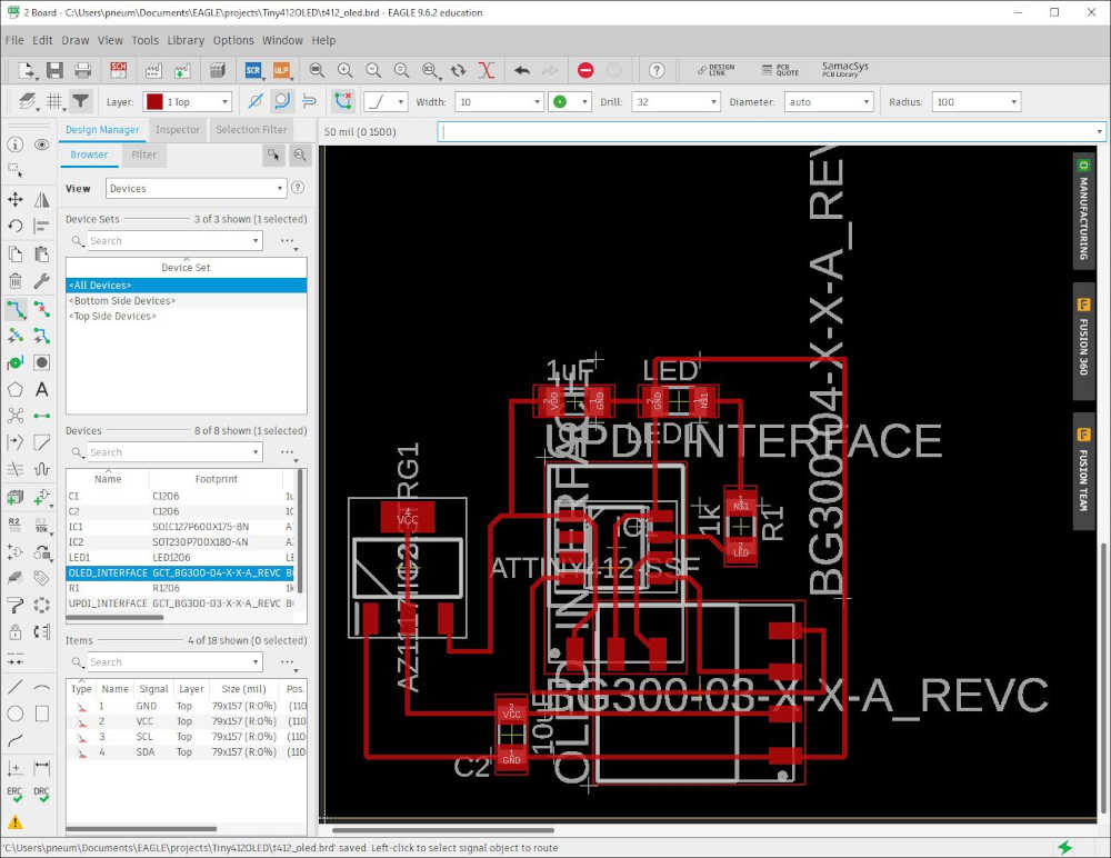
Everything was wired correctly and the DRC passed except for the UPDI and OLED Interfaces overlapping each other. I approved the warnings and moved on. This is the image of the top level:
The day was coming to an end, so I thought I better send this to a png and then to g-code:

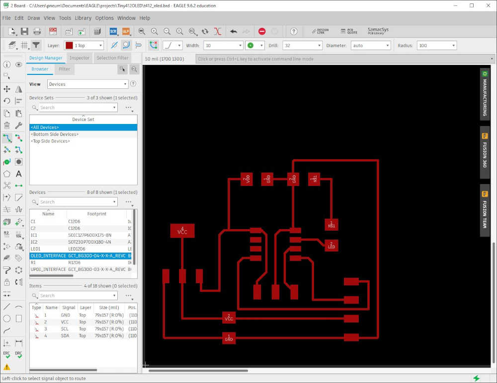
After sleeping on this, I was not satisfied with the interfaces laying on each other in the board view. I knew that they were electrically the same and I just had to rotate the connectors 180 degrees; however, I wanted to get it right in case somebody used this in the future. It required me to delete the names/labels on the connectors and flip them 180 degrees. I also discovered that I had the VCC and VDD mixed up in a couple places, so I fixed that too. This is the result in the schematic view:
Before:
After:
Now I have to reroute the airwires and all will be well. This is the result of that work:
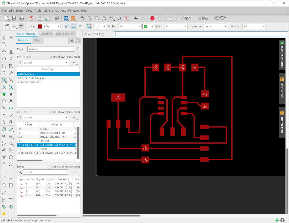
The top level didn’t change much, but I feel better about it now ;)
Next is exporting to a png and making the g-code.
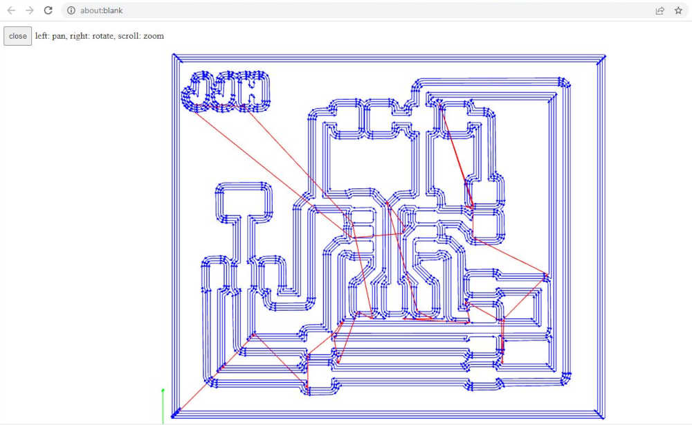
Traces:
Send the above to mods through G-code mill 2D PCB png as explained earlier (mill traces 1/64, spindle speed 1000, calculate):
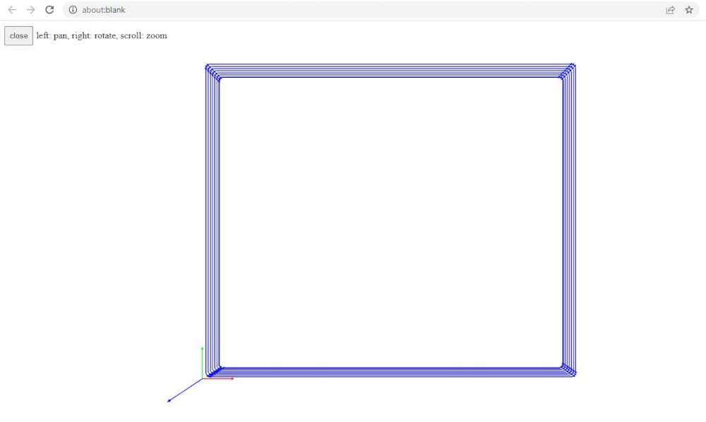
Interior:

Send the above to mods through G-code mill 2D PCB png as explained earlier (mill traces 1/32, spindle speed 1000, calculate):
Using the generated g-code, I send it to the Sweety mill (CNC3018Pro) I am using Grblcontrol(Candle Version 1.1.7). However, a line needs to be edited in the g-code or you will wait forever, so make sure you edit the following line:
G04 P1000 //Line 15 in my file
To this:
G04 P1 //Line 15 in my file
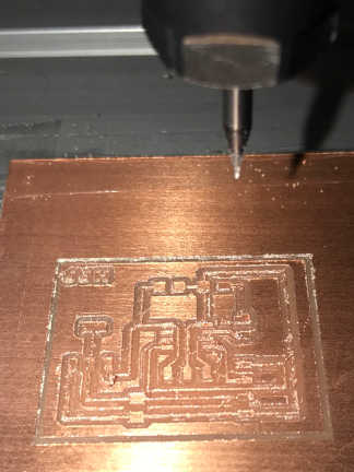
Before I actually cut the board, I cut air to make sure the dimensions were right; I’m so glad that I did! I used the same piece of FR-1 to make the ATTiny412 Basic board as well as the Serial-UPDI Interfaces. Turns out there was not enough real estate left, so I put a fresh board in. I discovered that putting a layer of regular plastic tape before the double-sided tape helps it stick to the wasteboard better, so I tried that. It’s amazing how much quiter the cutting is! It holds the board still, so there’s less vibration. We’ll see how it turns out ;)
Everything appears to be going smooth!
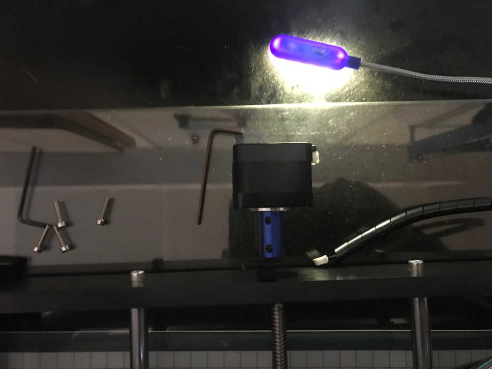
I began cutting out the interior board and during the last two laps, the Y-axis just stopped moving toward the front, but the spindle was still spinning. All of a sudden, it started milling toward the left and destroying my board!
I aborted the job and began investigating. The X and Z axis were working fine, but the Y axis stopped spinning the lead screw. I turned everything off and tried the lead screw by hand and it worked just fine. I plugged in the power and USB cable and tested again. The Y axis motor is responding, but it is not turning the lead screw. It appears the coupling is slipping on the motor side; I will have to disassemble the Y axis motor assembly to verify that is the problem.

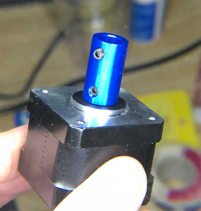
That was the problem. There is a flat side to the shaft on the stepper motor as well as rounded. There are two set screws 180 degrees from each other.
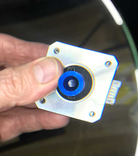
One set screw should be on the flat side and tightened first, followed by tightening the other.
The coupling was loose enough for the motor shaft to be pulled away without resistance. It is amazing that I was getting good results up to the moment it failed. Additionally, it is amazing that the 1/32 endmill did not break when it plowed though the entire depth of the circuit board. The board is 1/16” thick and the endmill is only 1/32”. That is twice the thickness it should cut and it did not fail. I will see how long it lasts until it needs to be replaced :)
I milled another board without any issues. There was very little deburring to do!
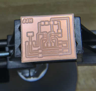
Stuffed t412_oled_board!!
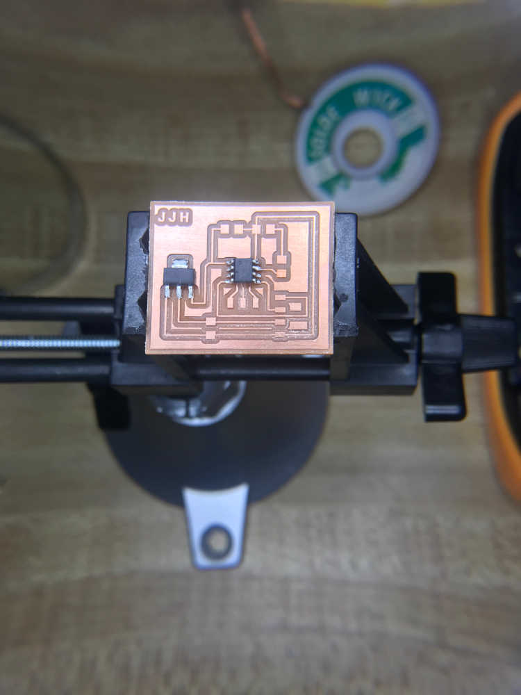
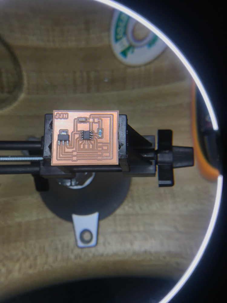
Programmed t412_oled_board!!
Sketch uses 904 bytes (22%) of program storage space. Maximum is 4096 bytes.
Global variables use 10 bytes (3%) of dynamic memory, leaving 246 bytes for local variables. Maximum is 256 bytes.
C:\Users\pneum\AppData\Local\Arduino15\packages\megaTinyCore\tools\python3\3.7.2-post1/python3 -u C:\Users\pneum\AppData\Local\Arduino15\packages\megaTinyCore\hardware\megaavr\2.5.11/tools/prog.py -t uart -u COM11 -b 230400 -d attiny412 --fuses 2:0x02 6:0x04 8:0x00 -fC:\Users\pneum\AppData\Local\Temp\arduino_build_172617/sosBlink.ino.hex -a write -v
SerialUPDI
UPDI programming for Arduino using a serial adapter
Based on pymcuprog, with significant modifications
By Quentin Bolsee and Spence Konde
Version 1.2.3 - Jan 2022
Using serial port COM11 at 230400 baud.
Target: attiny412
Set fuses: ['2:0x02', '6:0x04', '8:0x00']
Action: write
File: C:\Users\pneum\AppData\Local\Temp\arduino_build_172617/sosBlink.ino.hex
pymcuprog.programmer - INFO - Setting up programming session for 'attiny412'
pymcuprog.deviceinfo.deviceinfo - INFO - Looking for device attiny412
pymcuprog.serialupdi.physical - INFO - Opening port 'COM11' at '115200' baud
pymcuprog.serialupdi.link - INFO - STCS 08 to 0x03
pymcuprog.serialupdi.link - INFO - STCS 06 to 0x02
pymcuprog.serialupdi.link - INFO - LDCS from 0x00
pymcuprog.serialupdi.link - INFO - UPDI init OK
pymcuprog.serialupdi.link - INFO - STCS 06 to 0x02
pymcuprog.serialupdi.link - INFO - Setting UPDI clock to 8 MHz
pymcuprog.serialupdi.link - INFO - STCS 02 to 0x09
pymcuprog.serialupdi.physical - INFO - Switching to '230400' baud
pymcuprog.serialupdi.application - INFO - SIB: 'tinyAVR P:0D:0-3M2 (02.59B14.0)'
pymcuprog.serialupdi.application - INFO - Device family ID: 'tinyAVR'
pymcuprog.serialupdi.application - INFO - NVM interface: 'P:0'
pymcuprog.serialupdi.application - INFO - Debug interface: 'D:0'
pymcuprog.serialupdi.application - INFO - PDI oscillator: '3M2'
pymcuprog.serialupdi.application - INFO - Extra info: '(02.59B14.0)'
pymcuprog.serialupdi.application - INFO - Using 16-bit UPDI
pymcuprog.serialupdi.link - INFO - LDCS from 0x00
pymcuprog.serialupdi.application - INFO - PDI revision = 0x02
pymcuprog.serialupdi.link - INFO - LDCS from 0x0B
pymcuprog.serialupdi.link - INFO - LDCS from 0x0B
pymcuprog.serialupdi.application - INFO - Entering NVM programming mode
pymcuprog.serialupdi.link - INFO - LDCS from 0x07
pymcuprog.serialupdi.application - INFO - Apply reset
pymcuprog.serialupdi.link - INFO - STCS 59 to 0x08
pymcuprog.serialupdi.application - INFO - Release reset
pymcuprog.serialupdi.link - INFO - STCS 00 to 0x08
pymcuprog.serialupdi.link - INFO - LDCS from 0x0B
pymcuprog.serialupdi.link - INFO - LDCS from 0x0B
pymcuprog.serialupdi.link - INFO - LDCS from 0x0B
pymcuprog.serialupdi.link - INFO - LDCS from 0x0B
pymcuprog.serialupdi.link - INFO - LDCS from 0x0B
pymcuprog.nvm - INFO - No specific initializer for this provider
Pinging device...
pymcuprog.programmer - INFO - Reading device ID...
pymcuprog.serialupdi.application - INFO - SIB: 'tinyAVR P:0D:0-3M2 (02.59B14.0)'
pymcuprog.serialupdi.application - INFO - Device family ID: 'tinyAVR'
pymcuprog.serialupdi.application - INFO - NVM interface: 'P:0'
pymcuprog.serialupdi.application - INFO - Debug interface: 'D:0'
pymcuprog.serialupdi.application - INFO - PDI oscillator: '3M2'
pymcuprog.serialupdi.application - INFO - Extra info: '(02.59B14.0)'
pymcuprog.serialupdi.application - INFO - Using 16-bit UPDI
pymcuprog.serialupdi.link - INFO - LDCS from 0x00
pymcuprog.serialupdi.application - INFO - PDI revision = 0x02
pymcuprog.serialupdi.link - INFO - LDCS from 0x0B
pymcuprog.serialupdi.application - INFO - Device ID from pyupdi = '1E9223' rev 'C'
pymcuprog.nvm - INFO - Device ID: '1E9223'
pymcuprog.nvm - INFO - Device revision: 'C'
pymcuprog.nvm - INFO - Device serial number: 'b'304b444549306e851e1d''
Ping response: 1E9223
Setting fuse 0x2=0x2
Writing literal values...
pymcuprog.programmer - INFO - Write...
pymcuprog.programmer - INFO - Writing 1 bytes of data to fuses...
pymcuprog.programmer - INFO - Write complete.
Verifying literal values...
pymcuprog.programmer - INFO - Reading 1 bytes from fuses...
pymcuprog.programmer - INFO - Verifying...
Action took 0.19s
Setting fuse 0x6=0x4
Writing literal values...
pymcuprog.programmer - INFO - Write...
pymcuprog.programmer - INFO - Writing 1 bytes of data to fuses...
pymcuprog.programmer - INFO - Write complete.
Verifying literal values...
pymcuprog.programmer - INFO - Reading 1 bytes from fuses...
pymcuprog.programmer - INFO - Verifying...
Action took 0.19s
Setting fuse 0x8=0x0
Writing literal values...
pymcuprog.programmer - INFO - Write...
pymcuprog.programmer - INFO - Writing 1 bytes of data to fuses...
pymcuprog.programmer - INFO - Write complete.
Verifying literal values...
pymcuprog.programmer - INFO - Reading 1 bytes from fuses...
pymcuprog.programmer - INFO - Verifying...
Action took 0.19s
Finished writing fuses.
Chip/Bulk erase,
Memory type eeprom is conditionally erased (depending upon EESAVE fuse setting)
Memory type flash is always erased
Memory type lockbits is always erased
...
pymcuprog.programmer - INFO - Erase...
pymcuprog.serialupdi.nvm - INFO - Chip erase using NVM CTRL
Erased.
Action took 0.06s
Writing from hex file...
Writing flash...
pymcuprog.programmer - INFO - Write...
pymcuprog.programmer - INFO - Writing 904 bytes of data to flash...
[==================================================] 15/15
pymcuprog.programmer - INFO - Write complete.
Action took 1.10s
Verifying...
pymcuprog.programmer - INFO - Reading 904 bytes from flash...
[==================================================] 2/2
pymcuprog.programmer - INFO - Verifying...
Verify successful. Data in flash matches data in specified hex-file
Action took 0.15s
pymcuprog.serialupdi.application - INFO - Leaving NVM programming mode
pymcuprog.serialupdi.application - INFO - Apply reset
pymcuprog.serialupdi.link - INFO - STCS 59 to 0x08
pymcuprog.serialupdi.application - INFO - Release reset
pymcuprog.serialupdi.link - INFO - STCS 00 to 0x08
pymcuprog.serialupdi.link - INFO - STCS 0C to 0x03
pymcuprog.serialupdi.physical - INFO - Closing port 'COM11'
Tested t412_oled_board with SOS!!
1
Programmed t412_oled_board with Hello World!!
Sketch uses 3890 bytes (94%) of program storage space. Maximum is 4096 bytes.
Global variables use 28 bytes (10%) of dynamic memory, leaving 228 bytes for local variables. Maximum is 256 bytes.
C:\Users\pneum\AppData\Local\Arduino15\packages\megaTinyCore\tools\python3\3.7.2-post1/python3 -u C:\Users\pneum\AppData\Local\Arduino15\packages\megaTinyCore\hardware\megaavr\2.5.11/tools/prog.py -t uart -u COM11 -b 230400 -d attiny412 --fuses 2:0x02 6:0x04 8:0x00 -fC:\Users\pneum\AppData\Local\Temp\arduino_build_456985/ssd1306_128x64_i2c_take3.ino.hex -a write -v
SerialUPDI
UPDI programming for Arduino using a serial adapter
Based on pymcuprog, with significant modifications
By Quentin Bolsee and Spence Konde
Version 1.2.3 - Jan 2022
Using serial port COM11 at 230400 baud.
Target: attiny412
Set fuses: ['2:0x02', '6:0x04', '8:0x00']
Action: write
File: C:\Users\pneum\AppData\Local\Temp\arduino_build_456985/ssd1306_128x64_i2c_take3.ino.hex
pymcuprog.programmer - INFO - Setting up programming session for 'attiny412'
pymcuprog.deviceinfo.deviceinfo - INFO - Looking for device attiny412
pymcuprog.serialupdi.physical - INFO - Opening port 'COM11' at '115200' baud
pymcuprog.serialupdi.link - INFO - STCS 08 to 0x03
pymcuprog.serialupdi.link - INFO - STCS 06 to 0x02
pymcuprog.serialupdi.link - INFO - LDCS from 0x00
pymcuprog.serialupdi.link - INFO - UPDI init OK
pymcuprog.serialupdi.link - INFO - STCS 06 to 0x02
pymcuprog.serialupdi.link - INFO - Setting UPDI clock to 8 MHz
pymcuprog.serialupdi.link - INFO - STCS 02 to 0x09
pymcuprog.serialupdi.physical - INFO - Switching to '230400' baud
pymcuprog.serialupdi.application - INFO - SIB: 'tinyAVR P:0D:0-3M2 (02.59B14.0)'
pymcuprog.serialupdi.application - INFO - Device family ID: 'tinyAVR'
pymcuprog.serialupdi.application - INFO - NVM interface: 'P:0'
pymcuprog.serialupdi.application - INFO - Debug interface: 'D:0'
pymcuprog.serialupdi.application - INFO - PDI oscillator: '3M2'
pymcuprog.serialupdi.application - INFO - Extra info: '(02.59B14.0)'
pymcuprog.serialupdi.application - INFO - Using 16-bit UPDI
pymcuprog.serialupdi.link - INFO - LDCS from 0x00
pymcuprog.serialupdi.application - INFO - PDI revision = 0x02
pymcuprog.serialupdi.link - INFO - LDCS from 0x0B
pymcuprog.serialupdi.link - INFO - LDCS from 0x0B
pymcuprog.serialupdi.application - INFO - Entering NVM programming mode
pymcuprog.serialupdi.link - INFO - LDCS from 0x07
pymcuprog.serialupdi.application - INFO - Apply reset
pymcuprog.serialupdi.link - INFO - STCS 59 to 0x08
pymcuprog.serialupdi.application - INFO - Release reset
pymcuprog.serialupdi.link - INFO - STCS 00 to 0x08
pymcuprog.serialupdi.link - INFO - LDCS from 0x0B
pymcuprog.serialupdi.link - INFO - LDCS from 0x0B
pymcuprog.nvm - INFO - No specific initializer for this provider
Pinging device...
pymcuprog.programmer - INFO - Reading device ID...
pymcuprog.serialupdi.application - INFO - SIB: 'tinyAVR P:0D:0-3M2 (02.59B14.0)'
pymcuprog.serialupdi.application - INFO - Device family ID: 'tinyAVR'
pymcuprog.serialupdi.application - INFO - NVM interface: 'P:0'
pymcuprog.serialupdi.application - INFO - Debug interface: 'D:0'
pymcuprog.serialupdi.application - INFO - PDI oscillator: '3M2'
pymcuprog.serialupdi.application - INFO - Extra info: '(02.59B14.0)'
pymcuprog.serialupdi.application - INFO - Using 16-bit UPDI
pymcuprog.serialupdi.link - INFO - LDCS from 0x00
pymcuprog.serialupdi.application - INFO - PDI revision = 0x02
pymcuprog.serialupdi.link - INFO - LDCS from 0x0B
pymcuprog.serialupdi.application - INFO - Device ID from pyupdi = '1E9223' rev 'C'
pymcuprog.nvm - INFO - Device ID: '1E9223'
pymcuprog.nvm - INFO - Device revision: 'C'
pymcuprog.nvm - INFO - Device serial number: 'b'304b444549306e851e1d''
Ping response: 1E9223
Setting fuse 0x2=0x2
Writing literal values...
pymcuprog.programmer - INFO - Write...
pymcuprog.programmer - INFO - Writing 1 bytes of data to fuses...
pymcuprog.programmer - INFO - Write complete.
Verifying literal values...
pymcuprog.programmer - INFO - Reading 1 bytes from fuses...
pymcuprog.programmer - INFO - Verifying...
Action took 0.19s
Setting fuse 0x6=0x4
Writing literal values...
pymcuprog.programmer - INFO - Write...
pymcuprog.programmer - INFO - Writing 1 bytes of data to fuses...
pymcuprog.programmer - INFO - Write complete.
Verifying literal values...
pymcuprog.programmer - INFO - Reading 1 bytes from fuses...
pymcuprog.programmer - INFO - Verifying...
Action took 0.19s
Setting fuse 0x8=0x0
Writing literal values...
pymcuprog.programmer - INFO - Write...
pymcuprog.programmer - INFO - Writing 1 bytes of data to fuses...
pymcuprog.programmer - INFO - Write complete.
Verifying literal values...
pymcuprog.programmer - INFO - Reading 1 bytes from fuses...
pymcuprog.programmer - INFO - Verifying...
Action took 0.19s
Finished writing fuses.
Chip/Bulk erase,
Memory type eeprom is conditionally erased (depending upon EESAVE fuse setting)
Memory type flash is always erased
Memory type lockbits is always erased
...
pymcuprog.programmer - INFO - Erase...
pymcuprog.serialupdi.nvm - INFO - Chip erase using NVM CTRL
Erased.
Action took 0.06s
Writing from hex file...
Writing flash...
pymcuprog.programmer - INFO - Write...
pymcuprog.programmer - INFO - Writing 3890 bytes of data to flash...
[==================================================] 61/61
pymcuprog.programmer - INFO - Write complete.
Action took 4.22s
Verifying...
pymcuprog.programmer - INFO - Reading 3890 bytes from flash...
[==================================================] 8/8
pymcuprog.programmer - INFO - Verifying...
Verify successful. Data in flash matches data in specified hex-file
Action took 0.58s
pymcuprog.serialupdi.application - INFO - Leaving NVM programming mode
pymcuprog.serialupdi.application - INFO - Apply reset
pymcuprog.serialupdi.link - INFO - STCS 59 to 0x08
pymcuprog.serialupdi.application - INFO - Release reset
pymcuprog.serialupdi.link - INFO - STCS 00 to 0x08
pymcuprog.serialupdi.link - INFO - STCS 0C to 0x03
pymcuprog.serialupdi.physical - INFO - Closing port 'COM11'
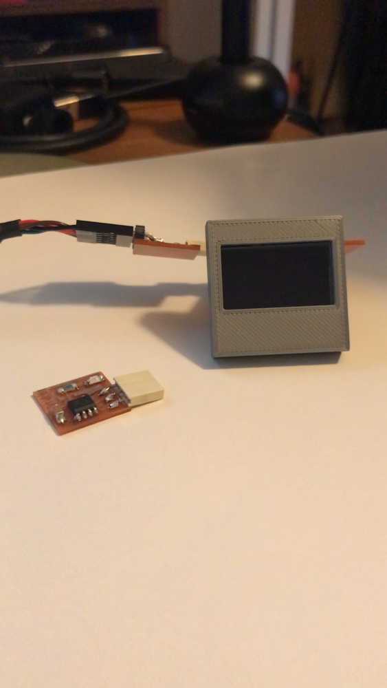
Tested t412_oled_board with Hello World!!!
Included a ‘hero shot’ of your board:
- Included a ‘hero shot’ of your board:
Included original source code and any new design files:
- Included original source code and any new design files:
Design Files and Source Code: Eagle, GIMP, Arduino, G-Code
Previous Research
-
Went through the electronic parts inventory to review what was available for the “displays” project listing. I intended to use the LCD display to prepare for its use in my final project. All parts are available.
-
Measured the power consumption of incandescent (100%), fluorescent (50%), and LED (25%) light bulbs.
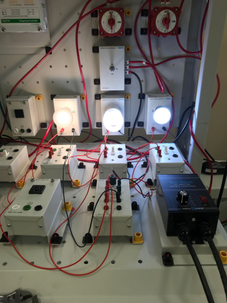
- incandescent (100% - 24 watts)
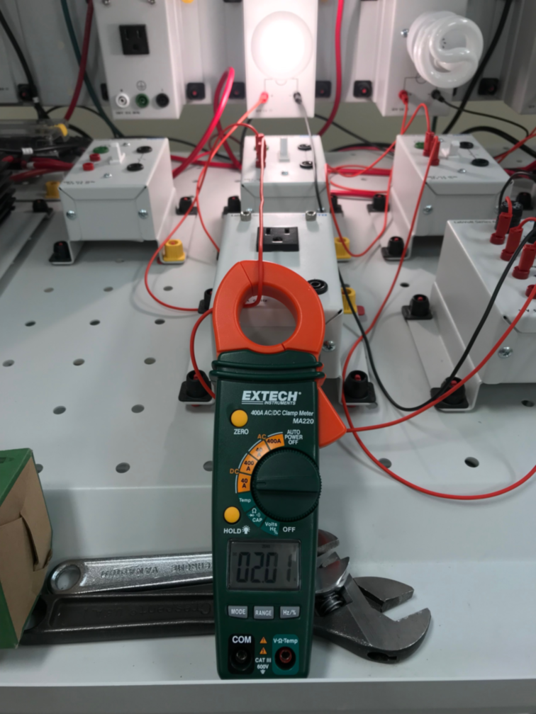
- fluorescent (50% - 12 watts)
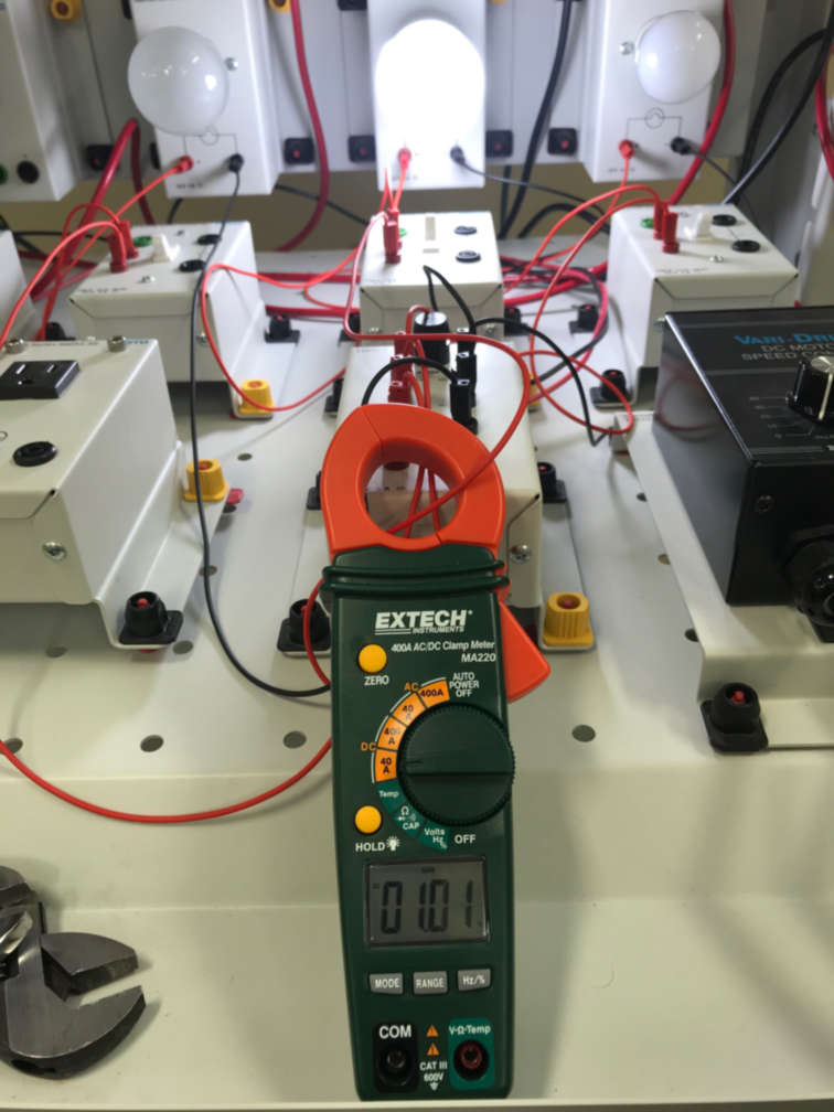
- LED (25% - 6 watts)

Results
In retrospect, I can see how much trouble I was having at this time. I felt like I had to do something, so I made a board designed by Neil, listed under displays in this unit’s material as hello.LCD.44. I knew I needed to have an output and I wanted to output the temperature. At the time, I could not imagine how that could be done. My only option was to imitate what Neil had done just to get the mechanics down. The following was the outcome of my early learning in the Fab Academy 2019 cycle. At the time, I had no idea I would be repeating this course at least 4 more times. I am happy to say that I did get the board working; although I did not design it. I still have difficulties with designing in Fab Academy 2023…
-
Description: Complete assignments and produce outcomes of Week 12 Output devices.
-
Requirements: Show how I made and programmed the board; explained any problems and how I fixed them; include a ‘hero shot’ of my board
-
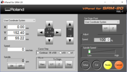
Planning: Setup the Roland SRM-20 mill for board production.
-
Materials: Using current laptop, internet connection, and Roland SRM-20 mill. Used acrylic boards to make a sacrificial platform. Solder station and supplies. Microcontroller: 1x ATTiny 44 microcontroller; Discrete devices: 1x Resonator 20MHz; 1x Resistor 1k ohm; 1x 10k ohm resistors; 1x Resistor 100k ohm; 1x IC 5.0v 100mA LDO Voltage Regulator; 1x Capacitor 1uF; 1x 2x2 pin header; 1x 2x3 pin header; 1x 2x5 pin header; 1x LCD Module
-
Problems: I made 2 test boards; 1 successful and 1 failed due to crashed 1/64 endmill in the process; I believe it was end of usefulness. The copper trace pulled away on the J2 power connector.
-
Corrections: Used the successful board. Only used the 2 pins for power.
-
Workflow: I used the mods to produce the LCD board. No problems in the use. Mods makes it so easy. Thank you, Neil!
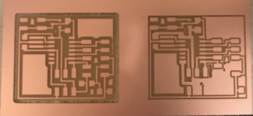
- Success: I made 2 boards. The second one had the endmill failure.
Code Example
jimhart@jimhart-Xubuntu2:~/display/displaytemp$ sudo make -f hello.video.44.make program-usbtiny
[sudo] password for jimhart:
avr-gcc -mmcu=attiny44 -Wall -Os -DF_CPU=20000000 -I./ -o hello.video.44.out hello.video.44.c
avr-objcopy -O ihex hello.video.44.out hello.video.44.c.hex;\
avr-size --mcu=attiny44 --format=avr hello.video.44.out
AVR Memory Usage
----------------
Device: attiny44

Program:     470 bytes (11.5% Full)
(.text + .data + .bootloader)

Data:          1 bytes (0.4% Full)
(.data + .bss + .noinit)


avrdude -p t44 -P usb -c usbtiny -U flash:w:hello.video.44.c.hex

avrdude: AVR device initialized and ready to accept instructions

Reading | ################################################## | 100% 0.00s

avrdude: Device signature = 0x1e9207 (probably t44)
avrdude: NOTE: "flash" memory has been specified, an erase cycle will be performed
         To disable this feature, specify the -D option.
avrdude: erasing chip
avrdude: reading input file "hello.video.44.c.hex"
avrdude: input file hello.video.44.c.hex auto detected as Intel Hex
avrdude: writing flash (470 bytes):

Writing | ################################################## | 100% 0.79s

avrdude: 470 bytes of flash written
avrdude: verifying flash memory against hello.video.44.c.hex:
avrdude: load data flash data from input file hello.video.44.c.hex:
avrdude: input file hello.video.44.c.hex auto detected as Intel Hex
avrdude: input file hello.video.44.c.hex contains 470 bytes
avrdude: reading on-chip flash data:

Reading | ################################################## | 100% 0.90s

avrdude: verifying ...
avrdude: 470 bytes of flash verified

avrdude: safemode: Fuses OK (E:FF, H:DF, L:62)

avrdude done.  Thank you.
At the end of the day, you just have to do something. So, this is toward the Final Project gotta get the NeoPixels working ;)
My plan is to use the Dev Board from XIAO: Big Power, Small Board See you tomorrow ;)
Well, I was going to use the Dev Board, but I decided to use the QuenTorres instead. I have been combing the internet looking for exact guidance, but have found a lot of different guides for different systems. Nothing quite like my setup, so I will need to improvise.
Adrian Torres gives guidance for an Adafruit NeoPixel Ring, so I plan to use his code to see what happens. I have the XIAO RP2040 connected to my computer through USB and using Arduino IDE 2.3.2. I loaded the neopixel.ino provided by Adrian and Clicked Compile. This is the error I received.
![]()
I knew I would receive the error because of the missing library Adrian told me about, so I searched for neopixel and you see the results guided me to the correct library. However, I became nervous and decided to do some more research.
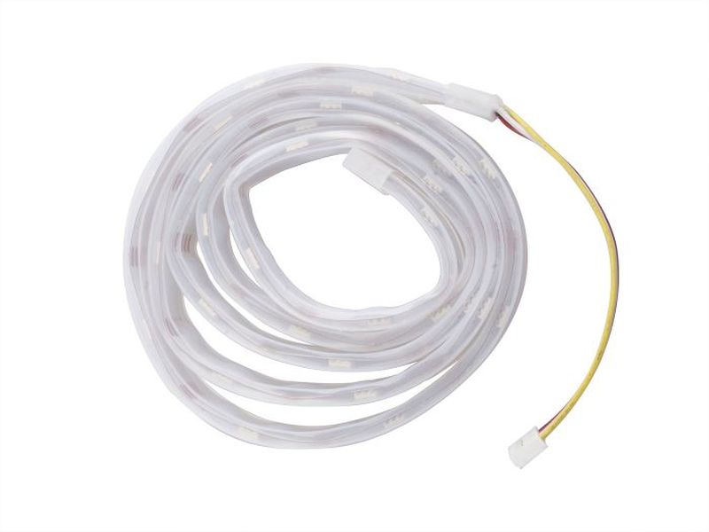
I have a Grove - WS2813 RGB LED Strip Waterproof - 30 LED/m - 1m. It has the WS2813 RGB LED rather than the WS2812 that Adrian is using. I was looking for the wiring diagram I had seen earlier, but could not find it. I found the neopixel tutorial I was hoping for XIAO: Big Power, Small Board They are using the exact strip that I have and also drive it using the Dev Board, so I will do that first.
This is the RGB LED Strip
And this is my setup
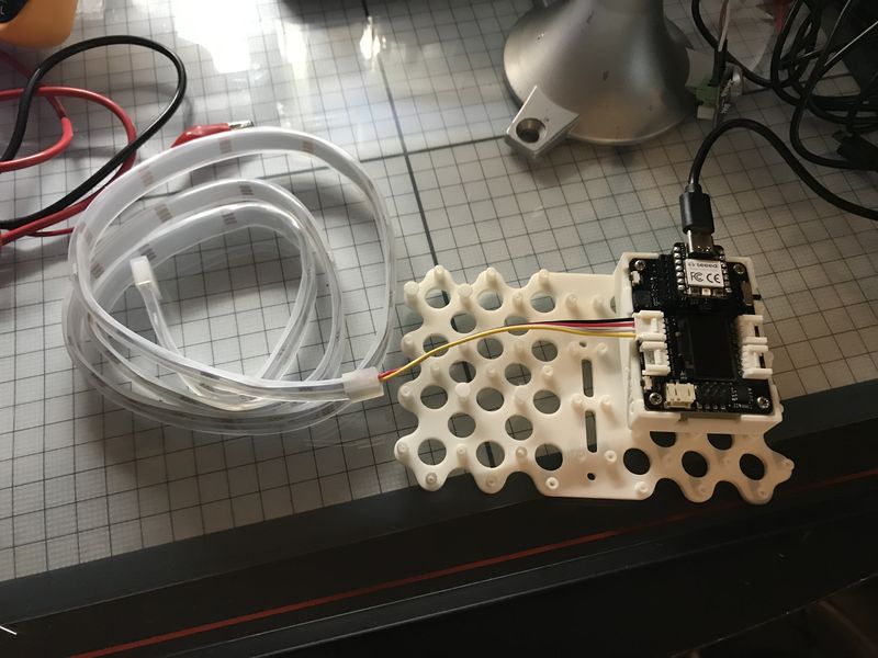
I have a feeling the library I found in the search was the correct one, but I will follow the tutorial recommendation to be safe. This is the guidance:
“Add the Adafruit_NeoPixel Library Before starting to program the RGB LED strip with the Arduino IDE, you need to add the necessary library files. Enter the library file address https://github.com/adafruit/Adafruit_NeoPixel in the browser address bar, enter the GitHub page, click Code→Download ZIP to download the resource package Adafruit_NeoPixel-master.zip to your local machine.”
It was the same library, so I justed installed it in the Arduino IDE.
![]()
I continued to follow the tutorial.
“Open the Simple Example You can open the simple example through the following path: File → Examples → Adafruit NeoPixel → simple. Once the example program is opened, we can see the following program:”
// NeoPixel Ring simple sketch (c) 2013 Shae Erisson
// Released under the GPLv3 license to match the rest of the
// Adafruit NeoPixel library

#include <Adafruit_NeoPixel.h>
#ifdef __AVR__
 #include <avr/power.h> // Required for 16 MHz Adafruit Trinket
#endif

// Which pin on the Arduino is connected to the NeoPixels?
#define PIN        6 // On Trinket or Gemma, suggest changing this to 1

// How many NeoPixels are attached to the Arduino?
#define NUMPIXELS 16 // Popular NeoPixel ring size

// When setting up the NeoPixel library, we tell it how many pixels,
// and which pin to use to send signals. Note that for older NeoPixel
// strips you might need to change the third parameter -- see the
// strandtest example for more information on possible values.
Adafruit_NeoPixel pixels(NUMPIXELS, PIN, NEO_GRB + NEO_KHZ800);

#define DELAYVAL 500 // Time (in milliseconds) to pause between pixels

void setup() {
  // These lines are specifically to support the Adafruit Trinket 5V 16 MHz.
  // Any other board, you can remove this part (but no harm leaving it):
#if defined(__AVR_ATtiny85__) && (F_CPU == 16000000)
  clock_prescale_set(clock_div_1);
#endif
  // END of Trinket-specific code.

  pixels.begin(); // INITIALIZE NeoPixel strip object (REQUIRED)
}

void loop() {
  pixels.clear(); // Set all pixel colors to 'off'

  // The first NeoPixel in a strand is #0, second is 1, all the way up
  // to the count of pixels minus one.
  for(int i=0; i<NUMPIXELS; i++) { // For each pixel...

    // pixels.Color() takes RGB values, from 0,0,0 up to 255,255,255
    // Here we're using a moderately bright green color:
    pixels.setPixelColor(i, pixels.Color(0, 150, 0));

    pixels.show();   // Send the updated pixel colors to the hardware.

    delay(DELAYVAL); // Pause before next pass through loop
  }
}
“This program allows the strip to light up 30 beads (green light) in sequence. This is a simple light strip example, and we need to modify some parameters:
#define PIN 0, you need to modify the pin connected to the light strip according to the actual situation. It is connected to the A0 interface of the XIAO expansion board, so it is PIN 0.
#define NUMPIXELS 30, defines the number of LEDs in the light strip. Since the light strip has different models and the number of integrated beads is different, we use a light strip with 30 beads, so it is NUMPIXELS 30.
After modifying the parameters, you can remove the English comments for a clearer view of the code. It occupies a large amount of space.”
This is the resultant code:
#include <Adafruit_NeoPixel.h> // Header file, declaring the library
#ifdef __AVR__
#include <avr/power.h>
#endif

#define PIN 0 // The light strip is connected to pin 0. If you are using XIAO RP2040, please change 0 to A0
#define NUMPIXELS 30 // The number of LED lights on the light strip
Adafruit_NeoPixel pixels(NUMPIXELS, PIN, NEO_GRB + NEO_KHZ800); // Create a new light strip object, define data mode
#define DELAYVAL 500 // The interval time for each light to light up

void setup() {
    #if defined(__AVR_ATtiny85__) && (F_CPU == 16000000)
    clock_prescale_set(clock_div_1);
    #endif
    pixels.begin(); // The light strip is ready to output data
}

void loop() {
    pixels.clear(); // All beads on the light strip are turned off
    for(int i=0; i<NUMPIXELS; i++) {
        pixels.setPixelColor(i, pixels.Color(0, 150, 0)); // Light up the beads in sequence, the color is green
        pixels.show(); // Display the light strip
        delay(DELAYVAL);
    }
}
Prototyping for the Final Project
The code compiled successfully.
I uploaded the code without errors, but the neopixels did not light :( I looked at the code and thought I should change the PIN to A0; then I saw the comment in the code, “If you are using XIAO RP2040, please change 0 to A0” Whoops! It has been a good learning experience. :)
![]()
Now for the exciting moment.
Now from the QuenTorres Dev Board :)
![]()
The purpose of this prototyping was to learn about the neopixel ring that will be used in the Final Project. I made some hardware and software adjustments to accomplish this.
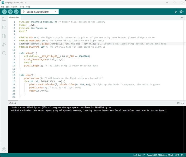
Now that I have fabricated the Fab_XIAO_FABCAT board and tested the Input Devices toward the bottom of the page, it is time to test the output devices I plan to use on the Final Project. As before, I will test the Grove - WS2813 RGB LED Strip Waterproof - 30 LED/m - 1m. Since it worked before on the code I have shown, I will use the same code, but directly from the Adafruit simple.ino provided in the File > Examples > Adafruit NeoPixels section. (Be sure to install the Adafruit NeoPixel Library) I compiled it first to be sure there were no errors. Then I successfully uploaded simple.ino after booting into the bootloader by pressing and holding the Boot button on the RP2040 while momentarily pressing the Reset button. This is the response I received.
![]()
And I get the nice green neopixels on the strip.
![]()
And now for the neopixel ring that I will be using in the Final Project. I saw that I did not list the neopixelRing.ino code that I used before, so I will list it here. I modified the simple.ino and made three different colors (Red, Green, Blue) light around the ring.
#include <Adafruit_NeoPixel.h> // Header file, declaring the library
#ifdef __AVR__
#include <avr/power.h>
#endif

#define PIN 6 // The neopixel ring is connected to pin 6.
#define NUMPIXELS 24 // The number of LED lights on the neopixel ring.
Adafruit_NeoPixel pixels(NUMPIXELS, PIN, NEO_GRB + NEO_KHZ800); // Create a new light strip object, define data mode
#define DELAYVAL 50 // The interval time for each light to light up

void setup() {
    #if defined(__AVR_ATtiny85__) && (F_CPU == 16000000)
    clock_prescale_set(clock_div_1);
    #endif
    pixels.begin(); // The light strip is ready to output data
}

void loop() {
    pixels.clear(); // All beads on the light strip are turned off
    for(int i=0; i<NUMPIXELS; i++) {
        pixels.setPixelColor(i, pixels.Color(25, 0, 0)); // Light up the beads in sequence, the color is red
        pixels.show(); // Display the light strip
        delay(DELAYVAL);
    }
    for(int i=0; i<NUMPIXELS; i++) {
        pixels.setPixelColor(i, pixels.Color(0, 25, 0)); // Light up the beads in sequence, the color is green
        pixels.show(); // Display the light strip
        delay(DELAYVAL);
    }
    for(int i=0; i<NUMPIXELS; i++) {
        pixels.setPixelColor(i, pixels.Color(0, 0, 25)); // Light up the beads in sequence, the color is blue
        pixels.show(); // Display the light strip
        delay(DELAYVAL);
    }
}
The code compiled successfully and uploaded to the Fab_XIAO_FABCAT board.
![]()
This is my setup for the neoPixel Ring connected to the Fab_XIAO_FABCAT board.
![]()
Now for the exciting moment.
This concludes my testing of the NeoPixel Ring as an output device for the Fab_XIAO_FABCAT board.