Project Development
This week I will:
- Complete my final project.
- Track and document my progress.
Learning Outcomes
- Create the project plan
- Track the progress of your project
- Summarise and communicate the essence of your project development
Checklist
During Week 1 and Week 2, I thought about my final project idea and started getting used to the documentation process. I will update this page as the idea transforms.
Communication of an initial project proposal
Introduction:
The initial project proposal has the intent of communicating the ultimate Final Project that I will be able to make after completing the 20 weeks of learning leading up to its completion. After discovering the Fab Academy, the prospect of being able make (almost) anything enables me to think of many ideas I have only dreamed of making before this time.
The projects that I complete as I work toward the Final Project will allow me to explore the possibilities, as well as refine the vision of the Final Project.
Scenario:
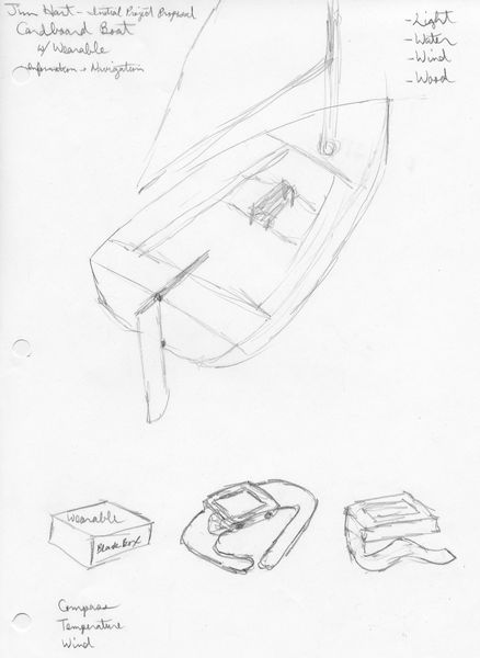
The greatest attraction that guided me to the Fab Academy was the desire to build a wooden sailboat; something that has been too lofty for my skill set. While this may be too ambitious for the timeframe allotted, a cardboard boat may be a more doable project.
Although a cardboard boat would be feasible, it only produces the first 3 outcomes, without producing the fourth: “Demonstrate competence in design, fabrication and programming of my own fabbed microcontroller PCB, including an input & output device”. To produce the fourth outcome, I propose making a wearable information and navigation device; one that would keep a sailor informed while underway.
While most of the parts will be obtained from existing resources, new and reused, the goal to design and fabricate my own parts instead of buying off-the-shelf components will be accomplished in the wearable information device.
As this work progresses, the projects of each week will be explored while the results will be incorporated into this project; the refinement of the results will insure the development of the carboard boat and wearable device as well as the following deliverables:
- Slide: 1920 x 1080 pixels with your name, project name, Fab Lab name, a photo/render/sketch of your project, a brief description of what your project is/does
- ~1 minute (10MB/1080p/720p) video of you explaining your project
- Separate Final Project page that briefly summarizes your project and
- BOM (Bill of Materials) for your project
- Links of page to any weeks that I worked on my final project
- Links to my presentation.png and presentation.mp4
- All original design files in the archive (2D & 3D, board files & code) No external hosting of final project files
- The license I chose
- Acknowledgement of work done by others
Deliverable:
- Post the Initial Project Proposal on my Fab Academy site
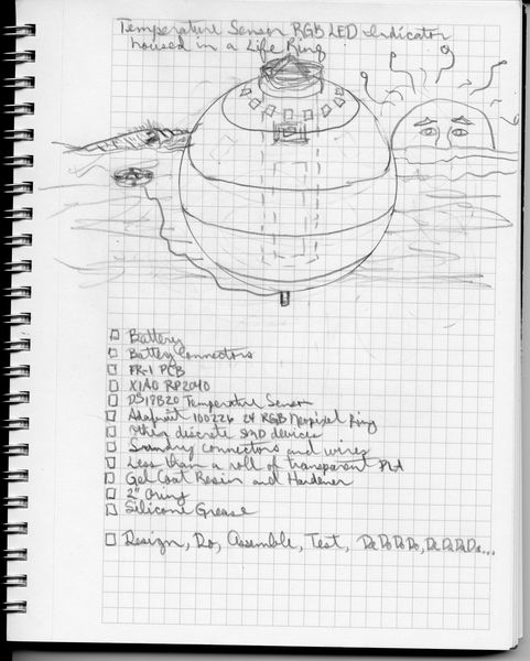
- After many iterations in Fab Academy, I have decided to focus on a single project within the original “many projects.” Returning to the challenge, “Demonstrate competence in design, fabrication and programming of my own fabbed microcontroller PCB, including an input & output device”. The Final Project has become a Smart Life Ring.
First, I need to design my own board that will accomplish the concept of this Final Project while keeping it simple ;) I will use the XIAO RP2040 on a board that provides power from an external LiPo battery, takes an input from a temperature sensor, and provide an output from a RGB LED.
Second, I need to design a sphere that will contain the electronics while keeping them safe from the water environment they will be in.
Finally, I will need to design a floatation device that keeps the sphere afloat while making it recoverable.
The following documentation consists of many spirals in Fab Academy.
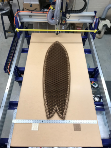
- I always wanted to be able to make a cardboard surfboard. Thanks, Mike Sheldrake! Cardboard Surfboards I will use this as a prototype for my final project. I’ll cut a 5‘10” Fish when I get back to the GOCAT Fab Lab.
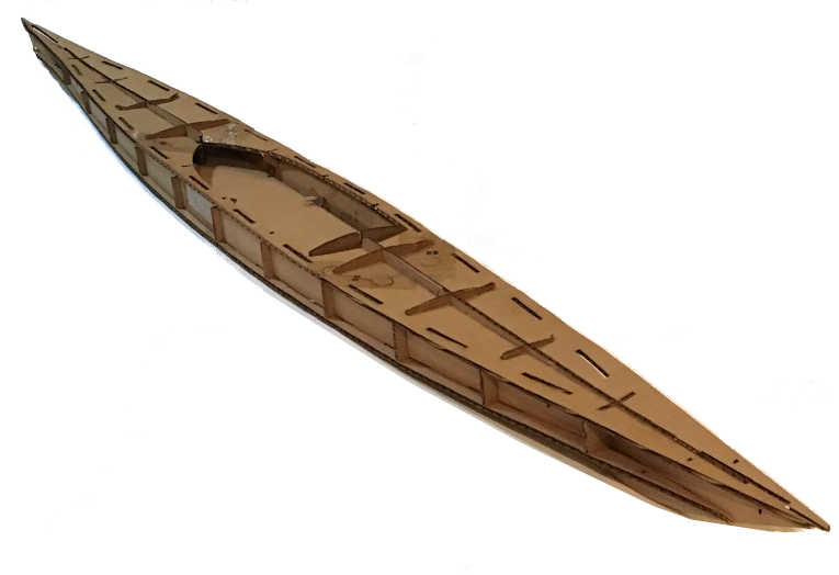
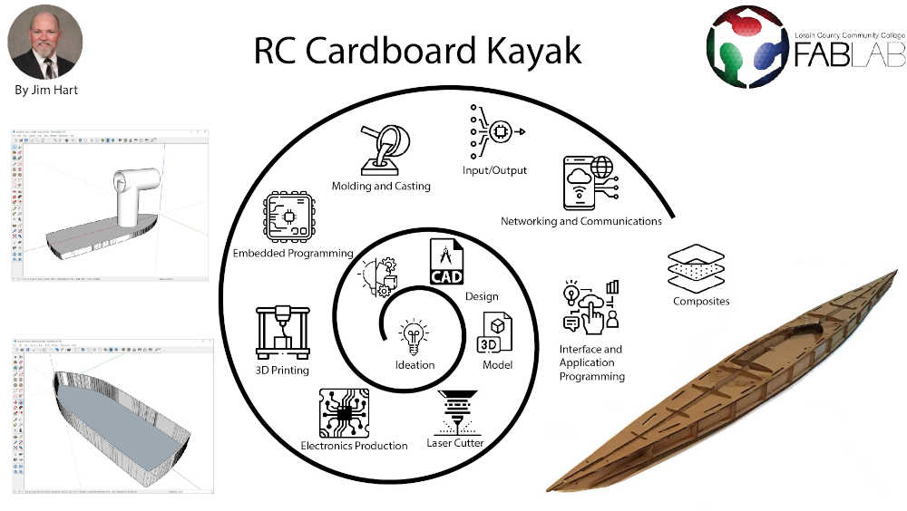
- This is a prototype of a cardboard kayak
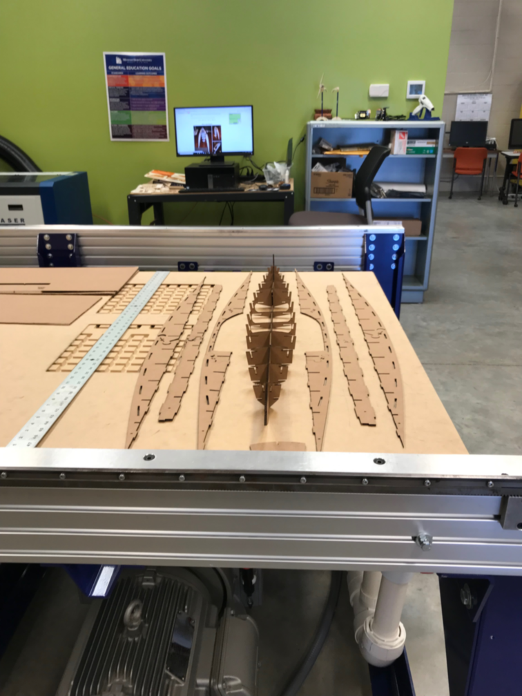
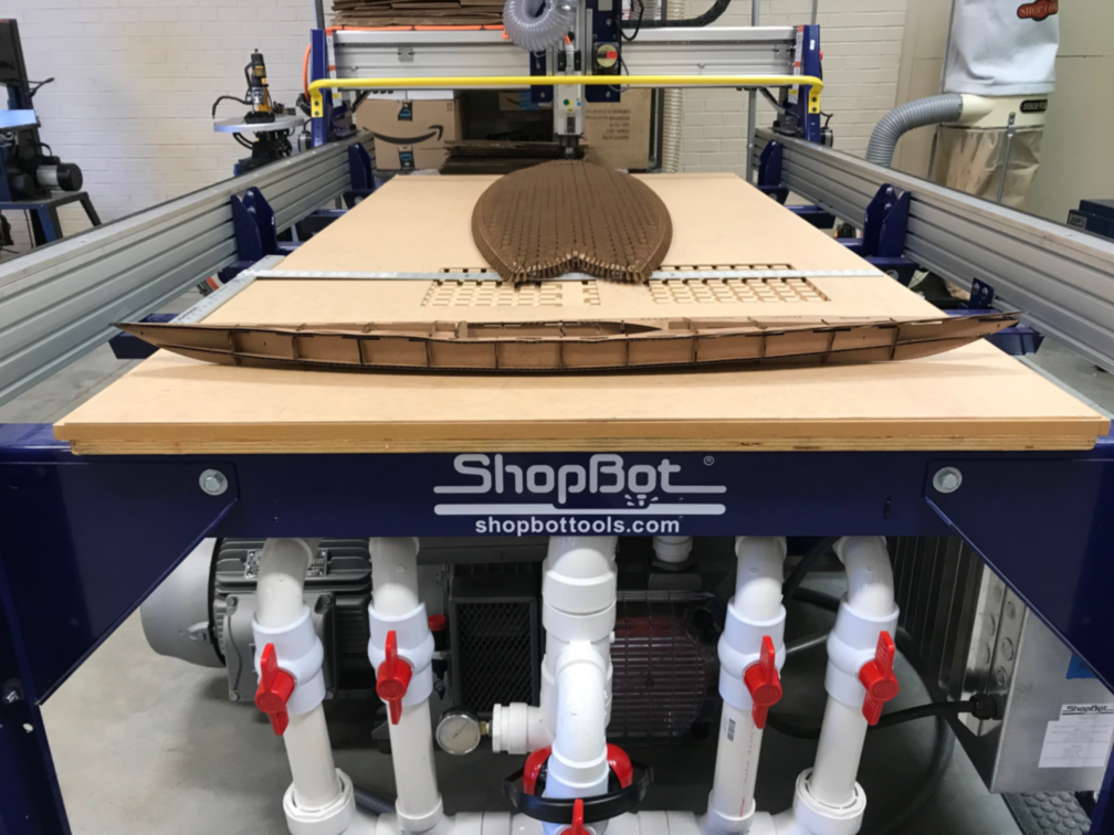
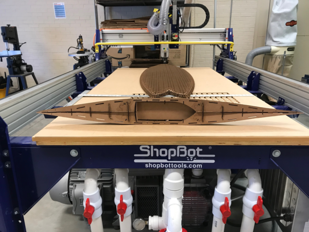
- Without access to a substantial laser cutter, I must use my prototype as the final project. I will be skinning the prototype and adding a propulsion pod.
- I will be placing the propusion pod in the cardboard kayak.
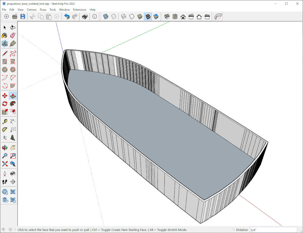
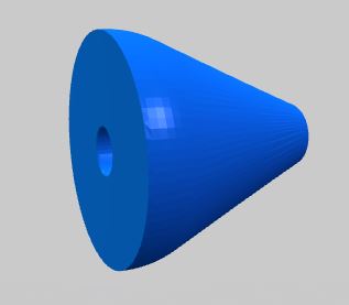
- This is the base of the propulsion pod.
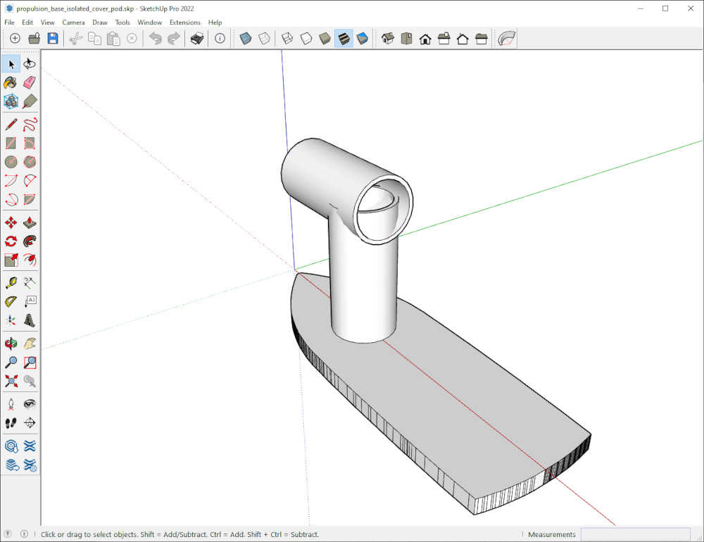
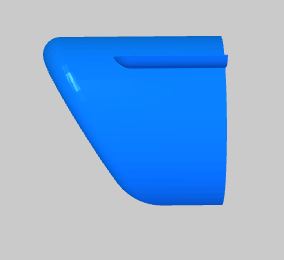
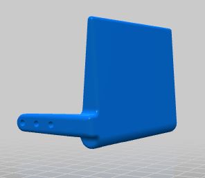
- This is the cover with a housing to mount the brushless DC motor used for propulsion.
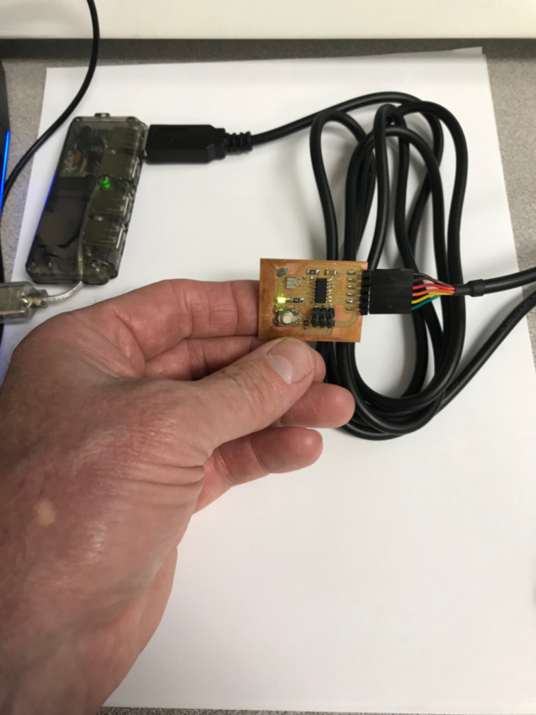
- This is my prototype of the distress signal board
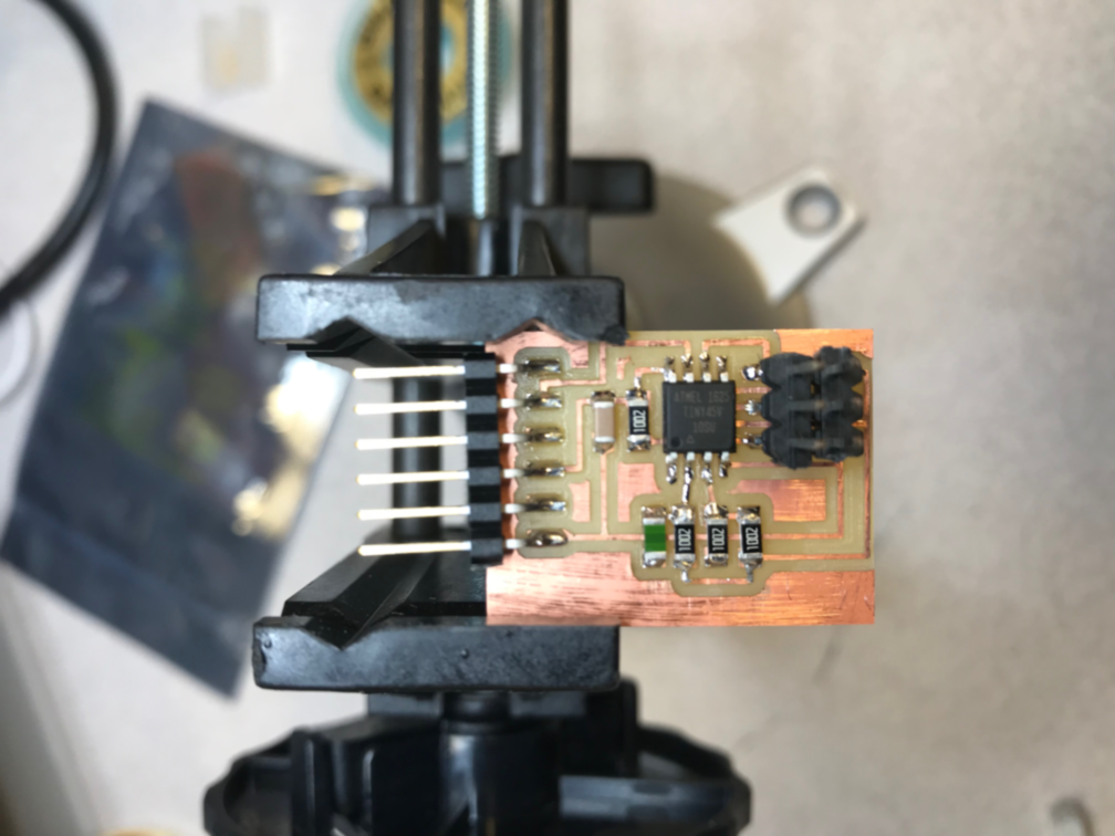
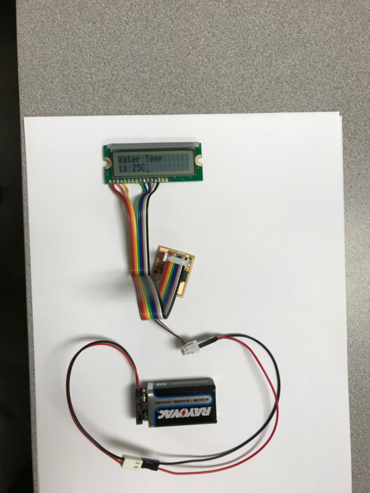
- This is my prototype of the temperature detection and readout
During the Fab Academy 2023 cycle, I had inspiration to further develop this final project during 3D Scanning and Printing week. I knew I would have to 3D print portions of the project, so I made a list:
-
Cardboard Kayak - Computer-Controlled Cutting and Composites
-
Cardboard Propulsion Pod - Computer-Controlled Cutting and Composites
-
Paper Tube Fairing - Elliptoid Vertical and Cylindrical Horizontal - 3D Print and Composites
-
Paper Tube Pontoons with 3D printed bow and stern fairing - Mechanical Design, 3D Print and Composites
-
Rudder Assembly - 3D Print
-
Wooden Cross Members - Computer-Controlled Machining, Composites, 3D Print
-
Brushless DC motor with ESC - 3D Print Mount and Output Devices
-
LiPO Battery - 3D Print Battery Compartment
-
Remote Control - Off the shelf
-
Temperature sensor and remote wearable display - 3D Print, Electronics Design and Production, Input Devices, Output Devices, Molding and Casting, Networking and Communications, Interface and Application Programming
-
Distress signal light - Networking and Communications
I looked on thingiverse for inspiration and found the design by CollegeEngineeringStudent RC Retrieval Pontoon Boat that might work.
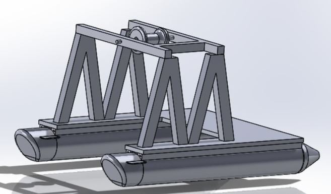
I intend to use fiberglass coated paper tubes as the pontoon with the bow and stern as 3D printed parts.
To steer the boat I intend to use a pair of rudders in the airstream mounted on the rear of the propulsion pod. They will be controlled by a servo motor.
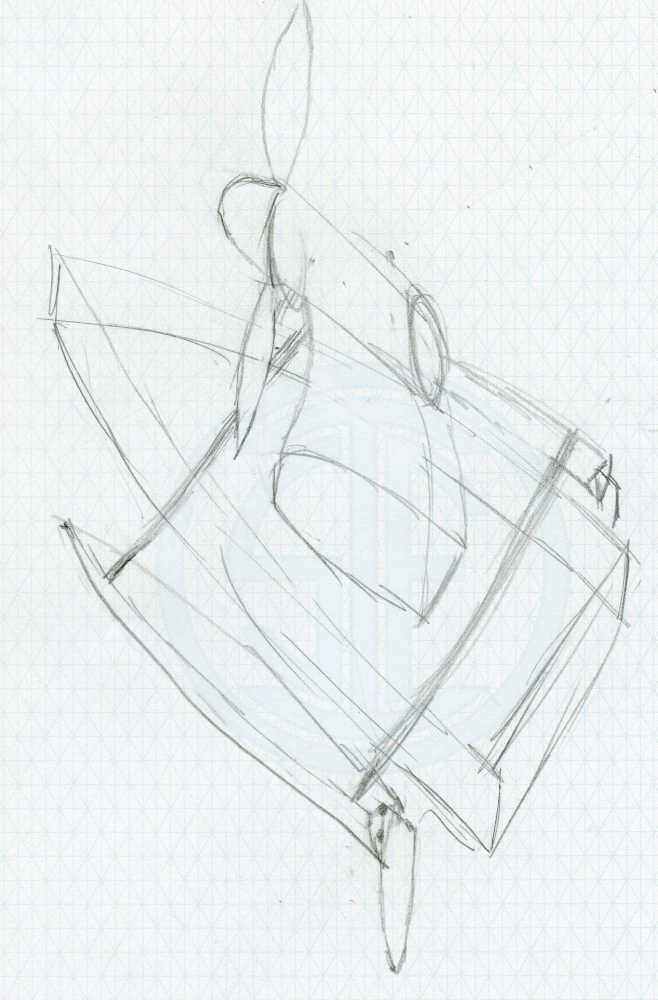
Pictures of a mockup of the Final Project idea:
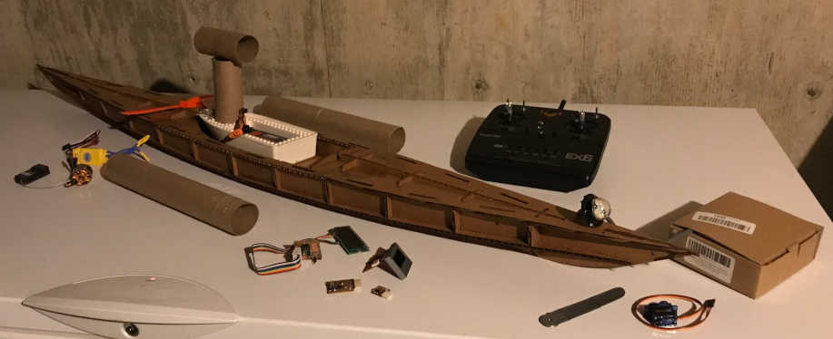
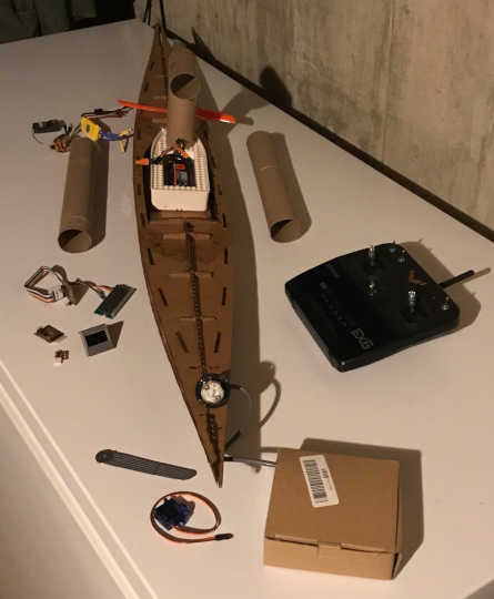
And a video for a better look:
The original Final Project consisted of many projects. With guidance from my Instructors, Pablo Nunez and Adrian Torres, as well as Rico Kanthatham the scope needs to be reduced. All progress toward the Final Project will be archived in the Project Development page. Content related to Managing Projects as presented by Norella Coronell and May El-Dardiry will be listed on this Final Project page.
What tasks have been completed?:
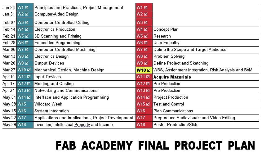
- What tasks have been completed?:
2 deliverables per week, one regarding the assignment (Globally) and the other the final project (Locally)
I have worked diligently on the above plan provided by Norella Coronell and May El-Dardiry; many thanks to them! I could not have done this without their direction.
What tasks remain?:
- What tasks remain?:
The checkmarks in the above schedule are based on work I have accomplished and the completion in Nueval. When my Local and Global Evaluators consider my work complete, I will adjust the Plan to reflect their approval. For all intents and purposes, I believe I have accomplished the requirements of each assignment. However, I have missed things before :)
What has worked? what hasn’t?:
- What has worked? what hasn’t?:
In a nutshell, this Cycle has worked; the previous Cycles did not work sufficiently to call this Course done. However, I have learned many valuable lessons along the way that have been applied to this Cycle. The greatest contribution to my success has been my Instructors coaching me, Rico Kanthatham introducing me to using VSCode and XnConvert for documentation, and the guidance of Norella and May with Project Management.
What questions need to be resolved?:
- What questions need to be resolved?:
Are my assignments sufficient? Did I document enough to demonstrate my understanding and accomplishment of the assignments. The answers to those questions will determine where I need to focus my attention.
What will happen when?:
- What will happen when?:
I am scheduled to present my Final Project to Professor Neil on Wednesday at the end of the session. You are welcome to join with us or view the video if you can’t be there. I have made every preparation to be ready, but I know there are many things that could be improved. I look forward to what I will learn in this last assignment of the Fab Academy 2024 Cycle.
What have you learned?:
- What have you learned?:
There is not sufficient time or space to record what I have learned over the past 8 years since my introduction to the Fab Academy. However, I do intend to give back to this Network as much as is humanly possible to repay the value that has been invested in my learning. Fab All-In is “Designed to increase belonging, expand (inclusive, urgent, enivro-social-econ-cultural-etc) impact, and create community.” I intend to be the embodiment of that concept with the intent to help others make it through the moments that I struggled with. I look forward to learning more!
My repo is filled with the lessons I have learned and will be updated as time allows and my mind recalls…to the end of my days.
This is a continuation of my learning and a compilation of how my ThermoSphere Final Project developed and utimately succeeded during my presentation on June 5, 2024.
W4 Concept Plan
-
Potential ideas for your final project with General Brainstorm and discussion with your local instructor.
-
Helps cancel unreachable ideas.
During Week 1 and Week 2, I thought about my final project idea and started getting used to the documentation process. I will update this page as the idea transforms.
Communication of an initial project proposal
Introduction:
The initial project proposal has the intent of communicating the ultimate Final Project that I will be able to make after completing the 20 weeks of learning leading up to its completion. After discovering the Fab Academy, the prospect of being able make (almost) anything enables me to think of many ideas I have only dreamed of making before this time.
The projects that I complete as I work toward the Final Project will allow me to explore the possibilities, as well as refine the vision of the Final Project.
Scenario:
The greatest attraction that guided me to the Fab Academy was the desire to build a wooden sailboat; something that has been too lofty for my skill set. While this may be too ambitious for the timeframe allotted, a cardboard boat may be a more doable project.
Although a cardboard boat would be feasible, it only produces the first 3 outcomes, without producing the fourth: “Demonstrate competence in design, fabrication and programming of my own fabbed microcontroller PCB, including an input & output device”. To produce the fourth outcome, I propose making a wearable information and navigation device; one that would keep a sailor informed while underway.
While most of the parts will be obtained from existing resources, new and reused, the goal to design and fabricate my own parts instead of buying off-the-shelf components will be accomplished in the wearable information device.
As this work progresses, the projects of each week will be explored while the results will be incorporated into this project; the refinement of the results will insure the development of the carboard boat and wearable device as well as the following deliverables:
- Slide: 1920 x 1080 pixels with your name, project name, Fab Lab name, a photo/render/sketch of your project, a brief description of what your project is/does
- ~1 minute (10MB/1080p/720p) video of you explaining your project
- Separate Final Project page that briefly summarizes your project and
- BOM (Bill of Materials) for your project
- Links of page to any weeks that I worked on my final project
- Links to my presentation.png and presentation.mp4
- All original design files in the archive (2D & 3D, board files & code) No external hosting of final project files
- The license I chose
- Acknowledgement of work done by others
Deliverables:
Assignment
- Post the Initial Project Proposal on my Fab Academy site
- Since this Final Project Plan begins with Week 4, the other assignments (Global) have been completed and documented on the following pages:
W1 Principles and Practices, Project Management W2 Computer-Aided Design W3 Computer-Controlled Cutting W4 Electronics Production
I will use these skills in portions of my Final Project and document where this occurs.
Final Project
- Keep It Simple
Rather than build a cardboard boat with electronics, build the electronics for Fab Academy, and then build the boat.
- Accomplish One Idea
Build a device that senses temperature and provides an output.
- Cancel Unreachables
I have not learned how to properly design a boat, but I do know how to design electronics. Put the boat in a drydock for a future spiral. Focus on electronics.
W5 Research
-
General to particular research, this should help students identify their topic, context and users.
-
Identify products that look similar to the concept of their project, for sure there are some parts that can contribute and you can direct better as an instructor.
Deliverables:
Final Project
-
Something Related to the Original Idea
-
Something Someone Has Done
Through collaboration with my Instructors we decided to make something that senses temperature and lights a RGB LED. This is related to my original idea and many people have done this.
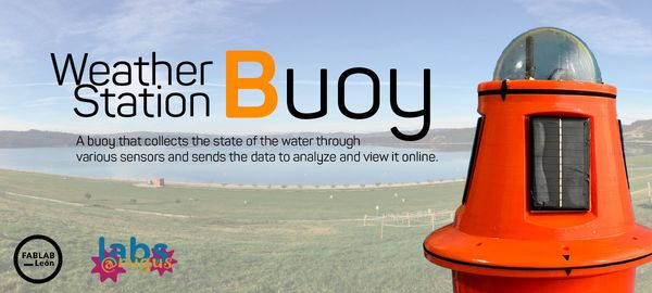
Adrian Torres recommended this Weather Station Buoy for inspiration.
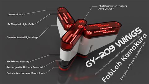
Rico Kanthatham inspired me with his Final Project.
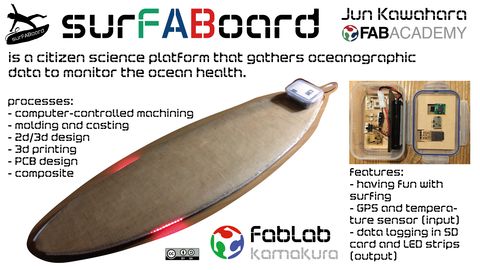
Rico also gave my guidance to another student from his Fab Lab, Jun Kawahara
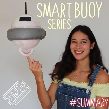
Through the Weather Station Buoy, I found additional inspiration for something more within my grasp with a smaller Smart Buoy.
In my wanderings I had an idea to change the Final Project completely; to an Automated Rat Trap. This was just another distraction (trap); although a good idea, it is not Simple.
W6 User Empathy
-
Create meaningful designs
-
What is the need? Will people be able to interact with your idea? Who finds this useful? Lab? Community? Country? World?
-
Human-centered Design
Deliverables
Assignment
This week my Instructors and I decided on a design that is meaningful, useful, and human-centered.
Reminder: Make a prototype of your project: Xiao + RGB LED (or led strips) + Temperature sensor. Connect in protoboard and program it.
Final Project
- Meaningful Design
Smart Life Ring
- Interact With Idea
Power Switch
- Useful To Who
Water Sports
- Human-centered Design
Life Ring for Water Rescue
Temperature Sensing to RGB LED Output Prototype
-
In an effort to focus my attention on the Final Project (so I can finish Fab Academy), my Remote Instructor, Pablo gave me an assignment to demonstrate the concept of giving an output (RGB LED) based on an input (temperature sensor). First, I needed to make a QuenTorres swd+uart adapter+hello board - XIAO RP2040 that I made in Electronics Production week to complete this assignment, so I ran out of time. However, I will still finish this assignment as I can.
-
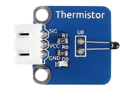
I have a lot of learning material that I have wanted to use, so I will document the learning process here. My plan is to use the SunFounder Sensor Kit V2.0 to become familiar with the concept. I plan to use the RGB LED Module
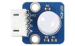
And the Thermistor Module
-
The tutorial calls for an Arduino, but I plan to use the XIAO RP2040 since my Instructor recommended this. I also have a nice development board to help me do this Seeed Studio XIAO Starter Kit I will be using the development board tutorial by SeeedStudio. So here we go.
-
First, I had to download and install Arduino IDE since this is a newer computer than the one I have been developing with. Seeed Studio gave me the link in the tutorial. Next, I had to add Seeed Studio XIAO to Arduino IDE. Since I have many of their boards, I added all three links as they recommended. It took quite a while to download. All three boards were installed.
-
Next I connected the RP2040 that I used in the QuenTorres board and plugged it into the Seeed Studio XIAO Expansion Board. I followed the instructions, but still received an error as before. What appears to be the RP2040 mounting its uf2 drive showed that drive in the Port list, so I selected that drive and tried again. It worked that time and the Port then went back to COM8. This is the output:
Sketch uses 52260 bytes (2%) of program storage space. Maximum is 2093056 bytes.
Global variables use 10232 bytes (3%) of dynamic memory, leaving 251912 bytes for local variables. Maximum is 262144 bytes.
Resetting COM8
Converting to uf2, output size: 140288, start address: 0x2000
Scanning for RP2040 devices
Flashing F: (RPI-RP2)
Wrote 140288 bytes to F:/NEW.UF2
-
So what I thought was a coding error before, was a misunderstanding on my part. Another learning opportunity! Once I communicated with the board, it worked every time.
-
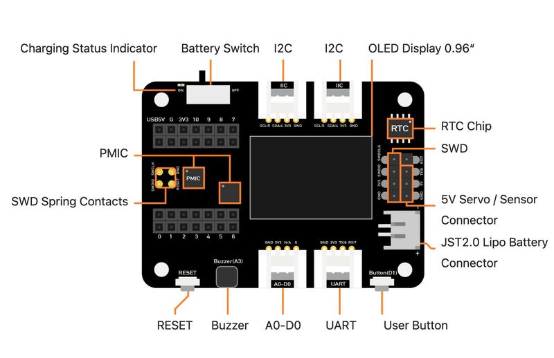
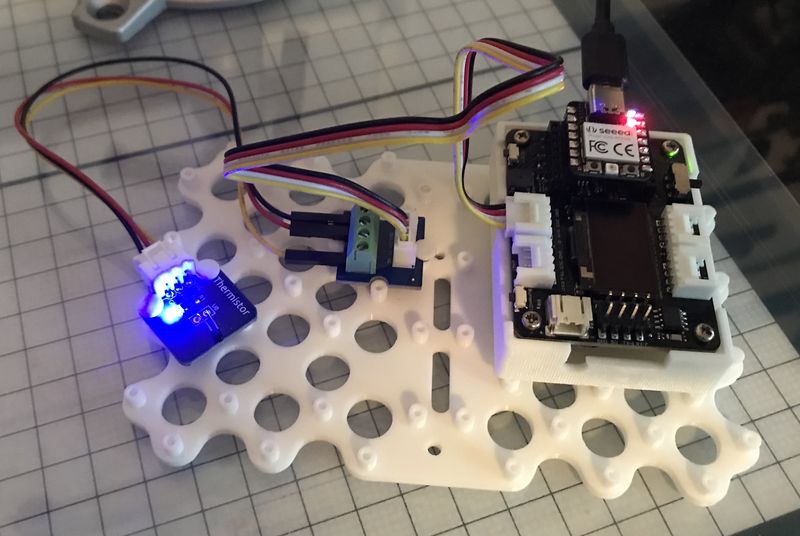
Now that I am on a roll, I will introduce you to the Seeed Studio XIAO Expansion Board. After I have a handle on the process and the programming, I hope to demonstrate with the QuenTorres.
-
This is the Seeed Studio XIAO Expansion Board.
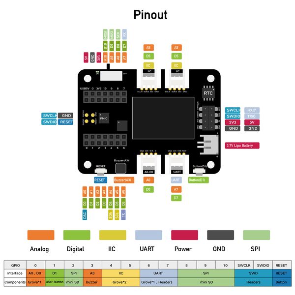
- This is the Seeed Studio XIAO Expansion Board pinout.
-
It is a very versatile board and I hope to make something similar in another spiral. For now, I will use it to detect temperature with the thermistor module.
-
As an interface between the modules, I will use a Grove Screw Terminal module
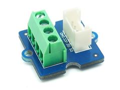
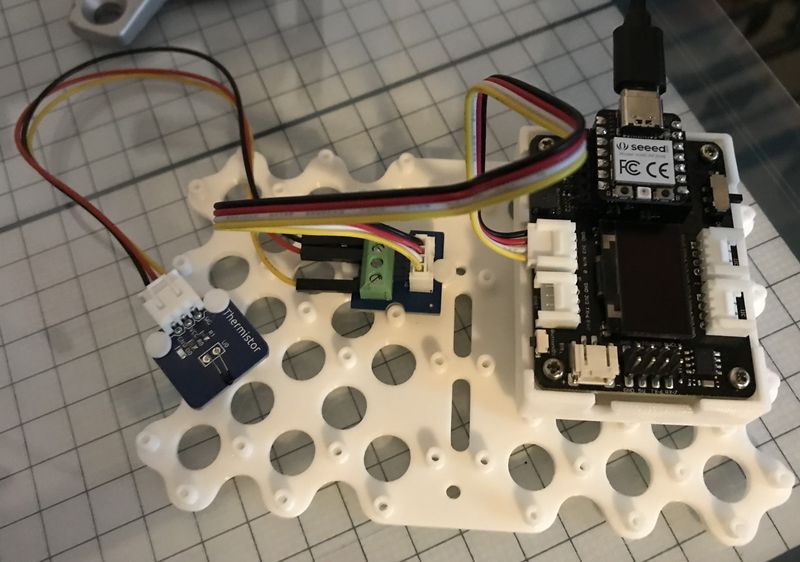
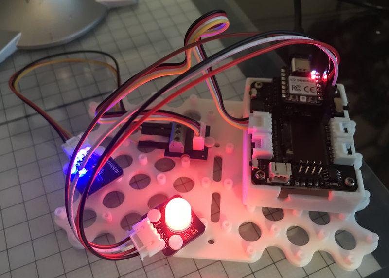
- This enables me to adapt a 3-wire device to a 4-wire connector without fabricating the cable. I will do this later, but this is for prototyping. Here you have the setup of the Temperature Prototype.
- This is the code I obtained from the Sensor Kit V2.0 for Arduino. It has been modified/commented out lines to exclude the use of a LCD display. I will only be using the serial monitor to see what is happening.
#include <Wire.h>
// #include <LiquidCrystal_I2C.h>
// initialize the library with the numbers of the interface pins
// LiquidCrystal_I2C lcd(0x27,16,2);  // set the LCD address to 0x27 for a 16 chars and 2 line display

#define analogPin  A0 //the thermistor attach to
#define beta 3950 //the beta of the thermistor
#define resistance 10 //the value of the pull-up resistor


void setup()
{
  // set up the LCD's number of columns and rows:
  // lcd.init();  //initialize the lcd
  // lcd.backlight();  //open the backlight
  Serial.begin(9600);
}

void loop()
{
  long a =1023 - analogRead(analogPin);  //read thermistor value
  Serial.print("Raw reading ");
  Serial.println(a);
  //the calculating formula of temperature
  float tempC = beta /(log((1025.0 * 10 / a - 10) / 10) + beta / 298.0) - 273.0;
  float tempF = 1.8*tempC + 32.0;
  Serial.print("Centigrade ");
  Serial.println(tempC);
  Serial.print("Fahrenheit ");
  Serial.println(tempF);
  Serial.println("");
  delay(1000);

  // // Print a message of "Temp: "to the LCD.
  // lcd.setCursor(0, 0);// set the cursor to column 0, line 0
  // lcd.print("Temp: ");  // Print a message of "Temp: "to the LCD.
  // lcd.print(tempC); // Print a centigrade temperature to the LCD.
  // // Print the unit of the centigrade temperature to the LCD.
  // lcd.write(char(223));
  // lcd.print("C");//print the unit" ℃  "
  // lcd.setCursor(0, 1);// set the cursor to column 0, line 1
  // lcd.print("Fahr: ");
  // lcd.print(tempF);// Print a Fahrenheit temperature to the LCD.
  // lcd.write(char(223)); // Print the unit of the Fahrenheit temperature to the LCD.
  // lcd.print(" F");//print the unit"°F"
  // delay(200); //wait for 100 milliseconds
}
- First I plug in the USB to the XIAO RP2040 I have mounted on the expansion board.
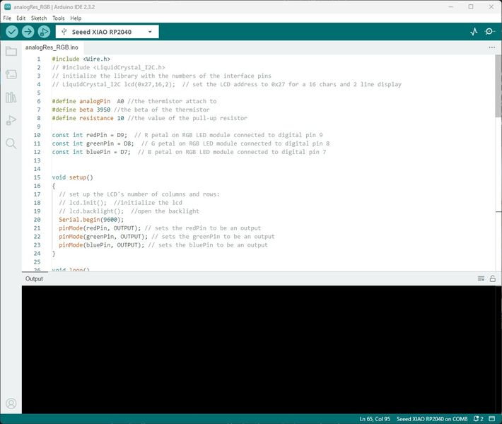
- Now I communicate with the XIAO using the Arduino IDE and open the analogRes.ino file.
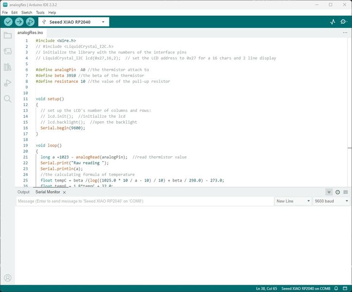
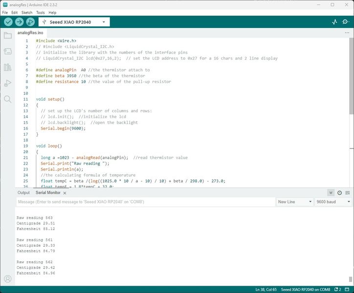
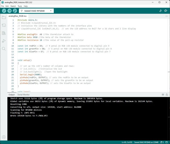
- I Click Upload and the file is compiled and uploaded and you can see the output in the Serial Monitor

- The Fahrenheit temperature is about 73 degrees in my Fab Lab and that is being displayed. When I touch the thermistor for about 30 seconds, you can see the temperature rises to almost 85 degrees.
-
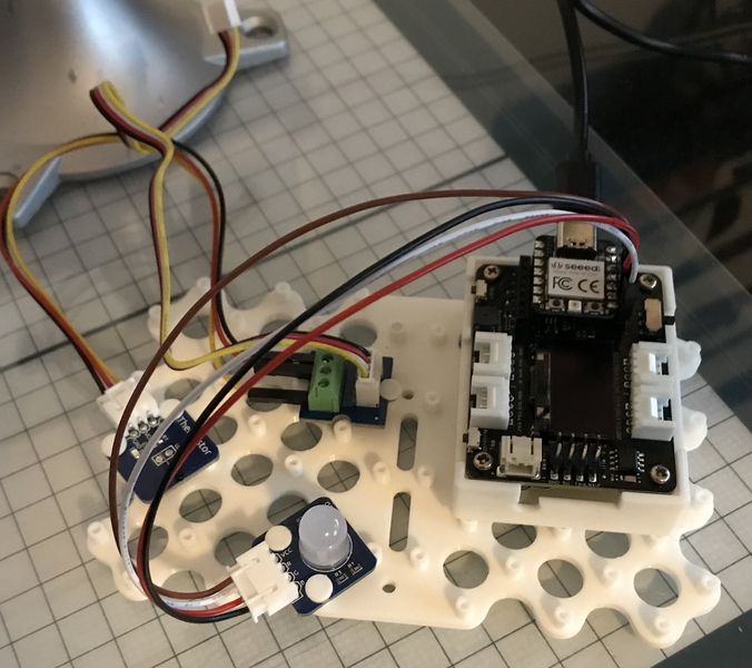
This concludes the test of the thermistor, now on to the RGB module :)
-
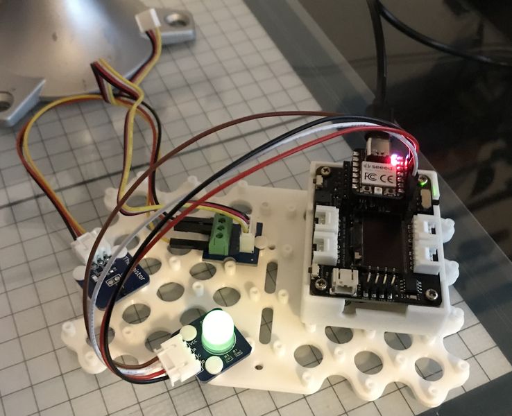
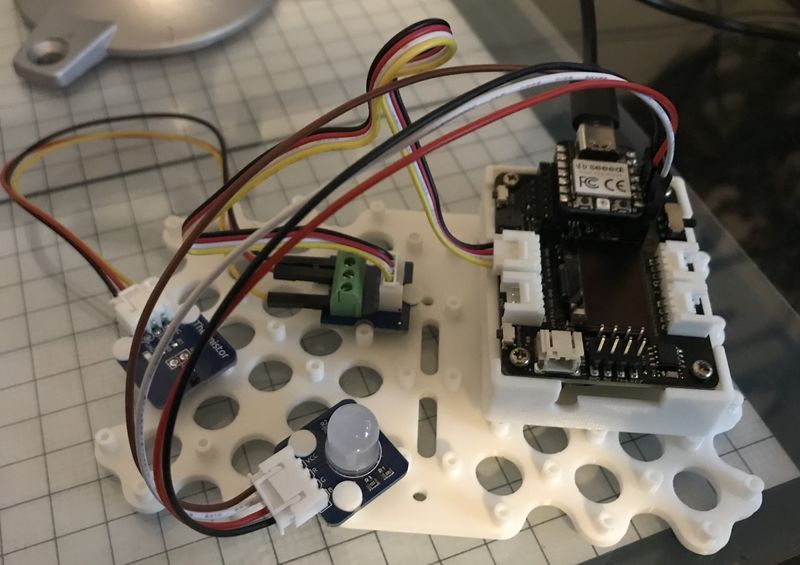
Here you have the setup of the RGB Prototype.
- This is the code I obtained from the Sensor Kit V2.0 for Arduino. It has been modified to use the XIAO RP2040 breakout pins on the expansion board: D7, D8, and D9. You can see the pinout in the image on the page above. I left the comments as is so you can see the difference between the pins used for the XIAO and the Arduino UNO.
/*************************************************************************
 * name:Rainbow LED
 * Function:you can see RGB LED flash red, green and blue first, and then change to red, orange, yellow, green, blue, indigo and purple.
 * Note:because the RGB module is common anode,so when you want to turn on a color ,you need to set it as 0
 ********************************************************************/
const int redPin = D9;  // R petal on RGB LED module connected to digital pin 11
const int greenPin = D8;  // G petal on RGB LED module connected to digital pin 10
const int bluePin = D7;  // B petal on RGB LED module connected to digital pin 9
/**************************************************************************/
void setup()
{
  pinMode(redPin, OUTPUT); // sets the redPin to be an output
  pinMode(greenPin, OUTPUT); // sets the greenPin to be an output
  pinMode(bluePin, OUTPUT); // sets the bluePin to be an output
}
/***************************************************************************/
void loop()  // run over and over again
{
  // Basic colors:
  color(0,255,255); // turn the RGB LED red
  delay(1000); // delay for 1 second
  color(255,0,255); // turn the RGB LED green
  delay(1000); // delay for 1 second
  color(255,255,0); // turn the RGB LED blue
  delay(1000); // delay for 1 second
  // Example blended colors:
  color(0,255,255); // turn the RGB LED red
  delay(1000); // delay for 1 second
  color(0,128,255); // turn the RGB LED orange
  delay(1000); // delay for 1 second
  color(0,0,255); // turn the RGB LED yellow
  delay(1000); // delay for 1 second
  color(255,0,255); // turn the RGB LED green
  delay(1000); // delay for 1 second
  color(255,255,0); // turn the RGB LED blue
  delay(1000); // delay for 1 second
  color(255,0,0); // turn the RGB LED  indigo
  delay(1000); // delay for 1 second
  color(128,255,0); // turn the RGB LED purple
  delay(1000); // delay for 1 second
}
/******************************************************/
void color (unsigned char red, unsigned char green, unsigned char blue)     // the color generating function
{
  analogWrite(redPin, red);
  analogWrite(bluePin, blue);
  analogWrite(greenPin, green);
}
/******************************************************/
- First I plug in the USB to the XIAO RP2040 I have mounted on the expansion board.
- Now I communicate with the XIAO using the Arduino IDE and open the RGB.ino file.
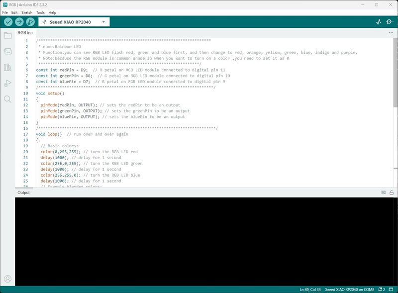
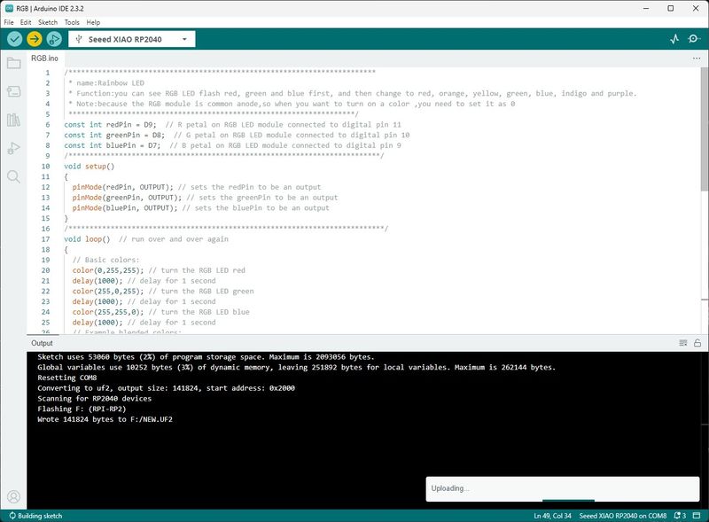
- I Click Upload and the file is compiled and uploaded and you can see the output in the Output panel.
- Here you can see the prototype in action :) Pretty colors!
-
This concludes the test of the RGB LED, now on to the making them work together :)
-
This is an exciting time for me because I have never got this far with my Final Project. I ‘m so thankful that my Instructor pointed my in the right direction. Keep it simple and accomplish your goal in small steps. I have been told that before, but I never seem to get it and then I get overwhelmed by all the possible details and potential failures. I guess I get the proverbial Analysis Paralysis :) Well here it goes!
-
Seeing the temperature readout and the RGB LED change was the success I needed to push forward to the goal. I have some programming experience, so I have the confidence to move forward. I recently had a lesson from my Instructor during Global Open Time about programming and really needed that for this project.
-
I started with the analogRes.ino listed above, saved it as analogRes_RGB.ino and copied and pasted the parts I thought I needed to make this work. This is what I ended up with.
#include <Wire.h>
// #include <LiquidCrystal_I2C.h>
// initialize the library with the numbers of the interface pins
// LiquidCrystal_I2C lcd(0x27,16,2);  // set the LCD address to 0x27 for a 16 chars and 2 line display

#define analogPin  A0 //the thermistor attach to
#define beta 3950 //the beta of the thermistor
#define resistance 10 //the value of the pull-up resistor

const int redPin = D9;  // R petal on RGB LED module connected to digital pin 9
const int greenPin = D8;  // G petal on RGB LED module connected to digital pin 8
const int bluePin = D7;  // B petal on RGB LED module connected to digital pin 7


void setup()
{
  // set up the LCD's number of columns and rows:
  // lcd.init();  //initialize the lcd
  // lcd.backlight();  //open the backlight
  Serial.begin(9600);
  pinMode(redPin, OUTPUT); // sets the redPin to be an output
  pinMode(greenPin, OUTPUT); // sets the greenPin to be an output
  pinMode(bluePin, OUTPUT); // sets the bluePin to be an output
}

void loop()
{
  long a =1023 - analogRead(analogPin);  //read thermistor value
  Serial.print("Raw reading ");
  Serial.println(a);
  //the calculating formula of temperature
  float tempC = beta /(log((1025.0 * 10 / a - 10) / 10) + beta / 298.0) - 273.0;
  float tempF = 1.8*tempC + 32.0;
  Serial.print("Centigrade ");
  Serial.println(tempC);
  Serial.print("Fahrenheit ");
  Serial.println(tempF);
  Serial.println("");
  delay(1000); //I put this in the loop because it was going too fast to observe
  if (tempF < 79) { //I selected this temperature since the ambient temperature is about 73 degrees
    color(255,255,0); // turn the RGB LED blue
    delay(1000); // delay for 1 second
  }
  else if (tempF > 79 && tempF < 83) { //I selected these temperatures since they are in the middle
    color(255,0,255); // turn the RGB LED green
    delay(1000); // delay for 1 second
  }
  else if (tempF > 83) { //I selected this temperature since it is below the temperature of my maximum 85 degrees
    color(0,255,255); // turn the RGB LED red
    delay(1000); // delay for 1 second
  }

 color(255,255,0); // turn the RGB LED blue
 delay(1000); // delay for 1 second


  //   // Basic colors:  I left this in the program as a reference
  // color(0,255,255); // turn the RGB LED red
  // delay(1000); // delay for 1 second
  // color(255,0,255); // turn the RGB LED green
  // delay(1000); // delay for 1 second
  // color(255,255,0); // turn the RGB LED blue
  // delay(1000); // delay for 1 second

  // // Print a message of "Temp: "to the LCD. I left this here in case I wanted an LCD output
  // lcd.setCursor(0, 0);// set the cursor to column 0, line 0
  // lcd.print("Temp: ");  // Print a message of "Temp: "to the LCD.
  // lcd.print(tempC); // Print a centigrade temperature to the LCD.
  // // Print the unit of the centigrade temperature to the LCD.
  // lcd.write(char(223));
  // lcd.print("C");//print the unit" ℃  "
  // lcd.setCursor(0, 1);// set the cursor to column 0, line 1
  // lcd.print("Fahr: ");
  // lcd.print(tempF);// Print a Fahrenheit temperature to the LCD.
  // lcd.write(char(223)); // Print the unit of the Fahrenheit temperature to the LCD.
  // lcd.print(" F");//print the unit"°F"
  // delay(200); //wait for 100 milliseconds
}

/******************************************************/
void color (unsigned char red, unsigned char green, unsigned char blue)     // the color generating function
{
  analogWrite(redPin, red);
  analogWrite(bluePin, blue);
  analogWrite(greenPin, green);
}
/******************************************************/
-
When I first ran the program, I had errors because I didn’t include “the color generating function”. At first I was confused because I thought it was a built-in function, but I was wrong. I looked at the RGB code again and found the function at the bottom. I also need to build intelligence into the code to make decisions (Just like Pablo said!) about the temperature and LEDs. At first, I thought the Case Stucture was the way to go, so I tried the structure and had a lot of trouble due to the floating point, so I used the IF/THEN/ELSE to keep it simple and easier to understand. The result is what you see above.
-
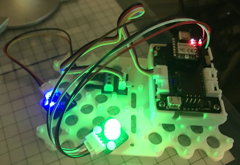
Now I will give it a try. Here you have the setup of the analogRES_RGB Prototype.
- First I plug in the USB to the XIAO RP2040 I have mounted on the expansion board.
- Now I communicate with the XIAO using the Arduino IDE and open the RGB.ino file.
- I Click Upload and the file is compiled and uploaded and you can see the output in the Output panel.
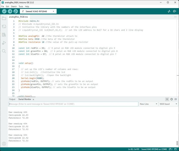
- Here you can see the output in the Serial Monitor.
- Here you can see the prototype in action. I just stays red!
-
This concludes the initial test of the analogRes_RGB Prototype, now on to the troubleshooting :)
-
To troubleshoot, I will need a greater difference in temperature. I have 3 cups, too hot, just right, and too cold; left to right, respectively.
-
To troubleshoot, I have placed a bit of code to change color to blue for one second to see what was going on. That was only confusing because the blue LED would come on momentarily and switch back to red.
-
When I touch “too hot” temperature goes to 93-94 degrees, “just right” 79-80 degrees, and “too cold” is 56-55 degrees. I adjusted the setpoints as follows:
  if (tempF < 65) { //I selected this temperature since the coldest temperature was 56-55 degrees
    color(255,255,0); // turn the RGB LED blue
    delay(1000); // delay for 1 second
  }
  else if (tempF > 75 && tempF < 85) { //I selected these temperatures since they are in the middle
    color(255,0,255); // turn the RGB LED green
    delay(1000); // delay for 1 second
  }
  else if (tempF > 85) { //I selected this temperature since it is below the temperature of hottest 93-94 degrees
    color(0,255,255); // turn the RGB LED red
    delay(1000); // delay for 1 second
-
I expect the light to be blue when it is “too cold”, but it stays red. Further investigation shows that the Red LED wire should be plugged into the D9 pin and the Blue LED wire should be plugged into the D7 pin; they were backwards! I switched them and all was well :)
-
This shows the Serial Monitor when the LED turns Blue for “Too Cold”.
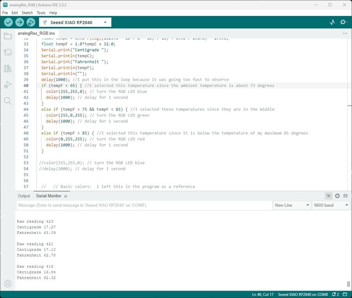
- This shows the Serial Monitor when the LED turns Green for “Just Right”.

- This shows the Serial Monitor when the LED turns Red for “Too Hot”.

- This is the video showing the above results with the long waits in between cut out. Changed the video from 58 seconds to 27 seconds to reduce the size.
- This concludes the troubleshooting and repairing of the analogRes_RGB Prototype, now on to making the PCB to house this concept :)
W7 Define the Scope and Target Audience
-
Bring your ideas back to earth, what is reachable?
-
This will help you guide them on what is possible based on the time they have to complete the project.
-
Study your context and target audience - For who are you designing?
Deliverables
Final Project
- Reachable Idea
Since I have accomplished the assignment from my Instructors, this makes the idea reachable. We have dialed in (focused) on an attainable goal; sense temperature of water and light a RGB LED with a board I have designed.
- Study Context and Audience
I studied the Smart Buoy and there is a lot packed into that little project. I plan to keep this simple ;) I will make a floating device that senses temperature and lights a RGB LED. My audience will have a need for safety while in the water. This Final Project will inform the swimmer and their audience about the safety of the swimmer.
W8 Problem Solving
-
Back to the 2 months left, What problem are you solving?It doesn’t have to solve worldwide problems. Innovativeideas usually solve a problem.
-
Will you be able to complete in 2 months? Phases!
Deliverables
Final Project
- Problem Final Project Solves
There are many problems to be solved, but the key is to finish Fab Academy so I can get on with helping others succeed. To do this I must keep it simple and accomplish my goals one step at a time without being overwhelmed by the prospect of future steps. My Instructors brilliantly enforced this by making me focus on each step/goal on the way to completion.
Ultimately, I want to teach others to succeed in Fab Academy while accomplishing their dreams for the future, while incorporating boat-centered thinking and designing. Rather than starting with the boat, we should start with surviving in the water. If you can’t swim, you will drown. If you can swim, but you get tired, you will drown. We need a floatation device when we are sinking; whether we can swim or not. This Final Project solves that problem. Just like Global Open Time solved that problem during the COVID crisis.
- Can you complete in 2 months?
My Instructors want me to make something that satisfies the requirements of the Final Project in 2 months so I will have time to improve it before I run out of time. That is such a wonderful idea; I give credit to my wise Instructors. Yes, I can complete in 2 months.
- List Phases
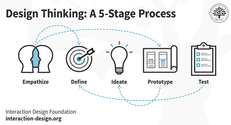
Design Thinking is a non-linear, iterative process that consists of 5 phases: 1. Empathize - what do your customers want when in and near the water? 2. Define - safety and enjoyment. 3. Ideate - how do we accomplish this? by providing safety while informing about the environment. 4. Prototype - sense the environment (temperature of water) and inform others (light a RGB LED) 5. Test - Make it and test it till it works.
You can carry out the stages in parallel, repeat them and circle back to a previous stage at any point in the process—you don’t have to follow them in order.
The 5 phases flow into each other from any direction, but they also inform in a non-linear and iterative process. In words, you Empathize with your users to help Define their needs, their problems, and your insights. You Ideate by challenging assumptions and create ideas for innovative solutions. Then you Prototype to start creating solutions; these prototypes provide opportunities to learn and spark new ideas. Be sure to Test the prototype solutions early and often to realize new ideas for the project while learning about your users and obtaining further insights that can redefine the problem.
So far, I have been doing this with the guidance of my Instructors. Now I know I can do this!
W9 Define Project and Sketching
-
Last chance to change aspects of your project.
-
Time Management
-
Create a solid structure to develop and create your final project idea.
Deliverables
Final Project
- Possible Changes
The thought forming after consulting with my Instructors was to make a ball to throw in the water, sense temperature, and light a RGB LED based on temperature.
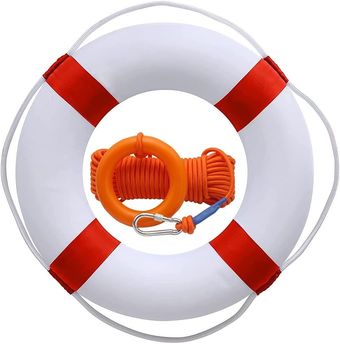
The problem was how to recover the device from the water. I decided on using a life ring with a safety lanyard to hold the device, so it could be recovered after use. This makes the project both informative and useful for water safety.
- Time Management
I really want to understand and apply Supply Side Time Management. What better time to learn and use this principle of time management!? I have been using Trello for project management, but I need to tweak it so it demonstrates supply side time management.
- Design Solid Structure of Idea
First, I need to design my own board that will accomplish the concept of this Final Project while keeping it simple ;) I will use the XIAO RP2040 on a board that provides power from an external LiPo battery, takes an input from a temperature sensor, and provide an output from a RGB LED.
Second, I need to design a sphere that will contain the electronics while keeping them safe from the water environment they will be in.
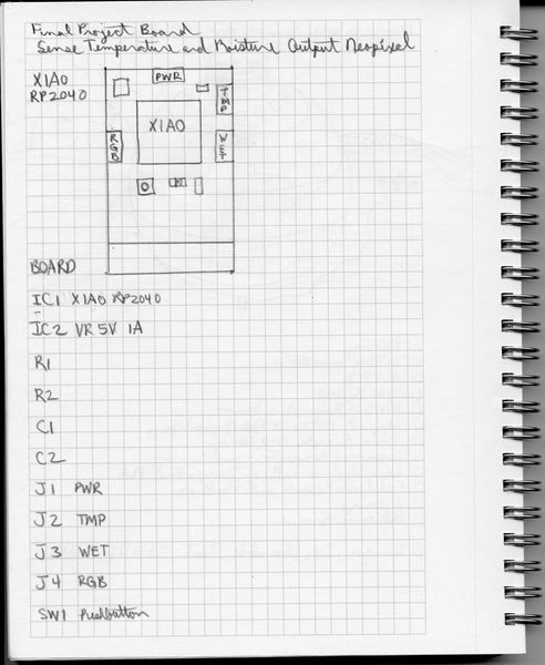
Finally, I will need to design a floatation device that keeps the sphere afloat while making it recoverable. So, here is a sketch of my Final Project at this point.
At the end of this iteration, I prototyped an Output Device for the Final Project. This allowed me to Ideate about the Final Project board design and the connectors I should use.
This pushed me forward to prototyping for the Input Device for the Final Project.
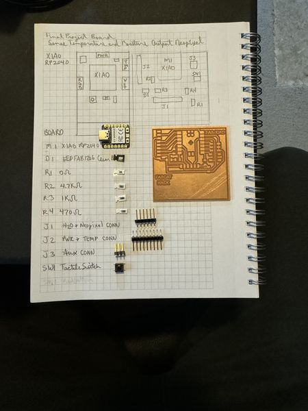
In order to make this happen, I will need to design a board to host the microcontroller and the connections necessary to receive the input and provide the appropriate output. Using the above list of materials, I have made a sketch of the initial concept of the board design.
This is an update of the Final Project Board prior to stuffing.
You can read more about this on the Electronics Design page.
In parallel with the conceptualizing of the board, I have also been thinking about the global structure of this project. I searched for an example of the globe I envisioned while I ordered a life ring to hold it in the center…I’m sure you noticed the life ring in the W6 User Empathy section ;) The life ring was in my mind’s eye, but making/designing the globe was a challenge. So I used the internet to search in Thingiverse.com for “sphere clear pla” because that was what I wanted and the material I intended to use. I got some really cool results, but the best was the Phillips Hue Globe Diffuser. THAT IS IT! I can work with that! So I researched a little bit. Turns out the author, ApatheticEnthusiasts (Robert Barton), did some research too. He summarized as, “This is a remix using parts from two things: Bottom and Top.” Eventually, I ended up with Fusion 360 design files from Abditus2 called the Sensor Sphere Box and the method of designing exactly what I need.
MAJOR NOTE: I did not design this globe from scratch. Let me reiterate, this design was obtained from Thingiverse.com and I was able to download the Fusion 360 files that Abditus2 provided back in December 04, 2018. I am able to manipulate the files and models to make the transformation I need. I did not use all of the models, just the plain sphere and the base unit. I will document the changes that I made so you can see what I have done.
This is the image of the design process, complete with the steps in Fusion 360.
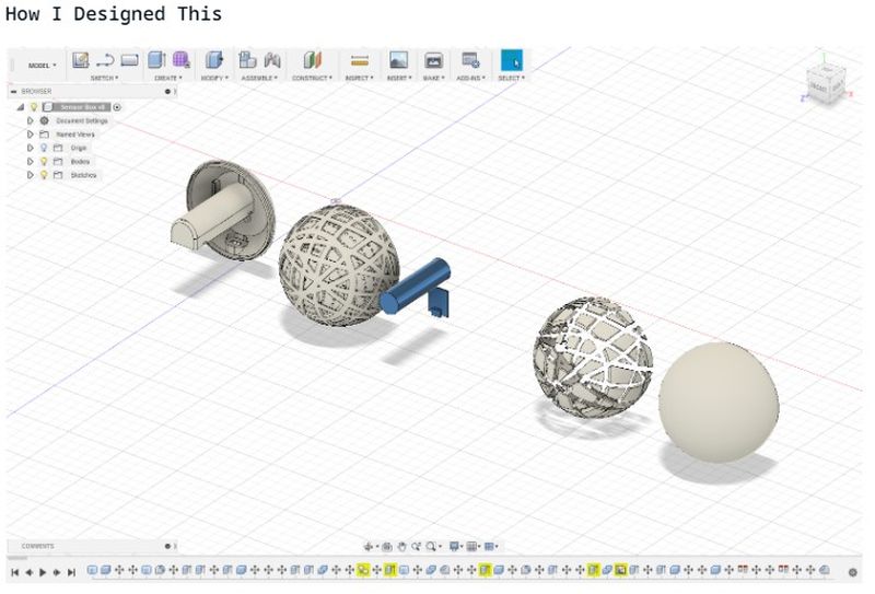
This is the internal design that really fits for what I am trying to do.
So I brought the file into Fusion 360, isolated the parts I was interested in, added a torus to represent the life ring, and I am well on my way to saving this Final Project :) More to follow!
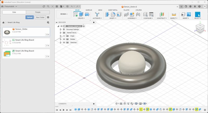
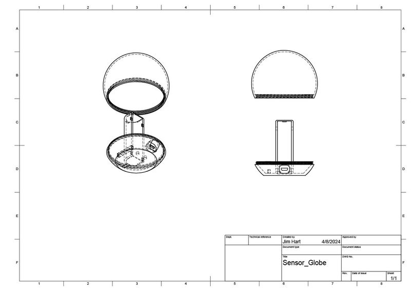
These are the drawings I made in Fusion 360. It took some time to figure out, but MAN, this is so cool!!!
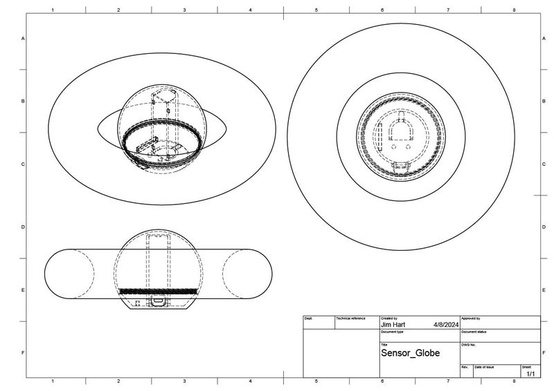
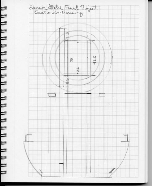
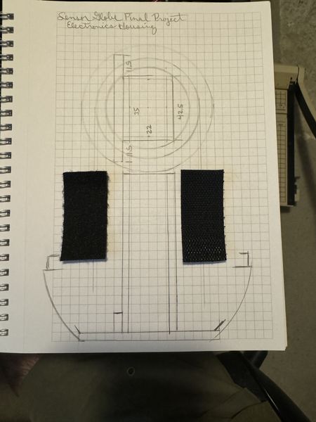
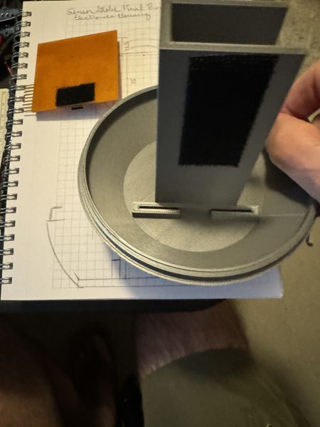
This is a sketch of the Electronics Housing (Globe Base) and what I intended to do with the provided model in order to house the internals of the sensor globe. The 35mm x 22mm rectangle is for the Battery Holder and the long and narrow rectangle is for the FABCAT Board Holder. The inner circle is the NeoPixel Ring.
I have modified the Electronics Housing to be my own. I really appreciate the starting point from the Phillips Hue Globe Diffuser who pointed me to Abditus2. I couldn’t have done it alone! I made it simple; Battery Holder, FABCAT Board Holder, Temperature Sensor Mount, and NeoPixel Ring Mount. If necessary, I will make separate mounts for the Screw Terminal Mounts, but I think they will be fine secured to the Battery Holder with hot glue and hook and latch material.
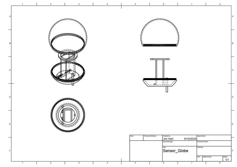
I will put a video here so you can see how I made the transformation. In a nutshell, I removed the internals of Abditus2’s model and replaced them with my own to fit the internal components I will be using. I also modelled a NeoPixel Ring so I could figure out what height it had to be at in my new design. This was probably the coolest thing about it; I literally moved the parts around as if I was using my hands and it really helped with visualizing what I was trying to do. Lastly, I made a hole in the bottom for the temperature sensor and then extruded it so you could see what it would look like. Everything is to scale for the components I will be using; Battery, FABCAT Board, Temperature Sensor, and NeoPixel Ring. I measured them and used the dimensions is the designing process. Fab Academy has really strengthened me in the 2D and 3D design area because I have to do this to realize the full potential of digital fabrication. I’m getting there, but slower than most. Accomplishing what I am about to show you was challenging for me, but I feel like I have accomplished a major milestone in my modelling journey. I hope this helps some students in the future. It was tricky to select every surface before deleting things; sometimes the whole part disappeared and I had to rewind. I hope you enjoy the show ;)
My intention is to add to this Final Project in spirals with the time I have, so it will need to be a flexible/temporary design. Having a threaded globe allows me to make changes while making the design as simple as possible. My plan is to secure the components in the Electronics Housing with hot glue as well as hook and latch material; this allows for changing things as the project develops in spirals without having to reprint the Electronic Housing (Globe Base). This will allow me to fasten additional boards to the Battery Holder on the outside as well as fasten the battery to the inside of the Battery Holder. This design will also allow recharging the battery without having potential leaks through external connectors; in other words, easily remove the battery for recharging.
W10 WBS, Assignment Integration, Risk Analysis and BoM
-
WBS- Work Breakdown Structure (Activities, timeframes, needs, wants, haves)
-
Everything is important but focus on what you will need- What assignments for your final project?
-
What happens if somethings goes wrong?
-
Bill of Materials - hand in to your local instructors
Deliverables
Final Project
- WBS- Work Breakdown Structure (Activities, timeframes, needs, wants, haves)
To make the Work Breakdown Structure (WBS) I used a tool I thought was useful in the past, but never really got to explore it. I have an account with Lucid so I dusted this app off and went to work. This would be a good entry for the Project Management documentation. I will have to add that in another spiral. (Note To Self: Add this to Week1)
The the app has many templates to use and WBS was one of them, so I used the template and added my own information and this is what I have.
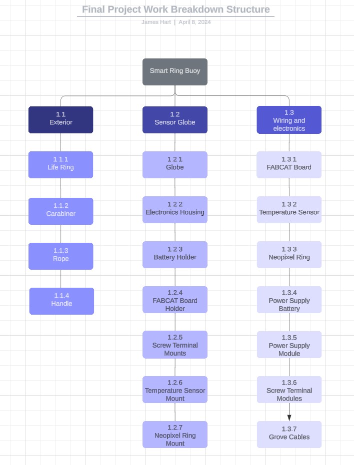
The timeframe is shown at the end of this section. The needs: I need to finish; to do that I will sense temperature and light a neopixel ring. I als want to sense whether there is leakage in the sensor globe and I want a power switch to turn the sensor globe on and off. I have everything to do these things, but I have to finish. Therefore, I will keep it simple. If I have time, I will do more of my wants, but for now…keep it simple.
- Everything is important but focus on what you will need- What assignments for your final project?
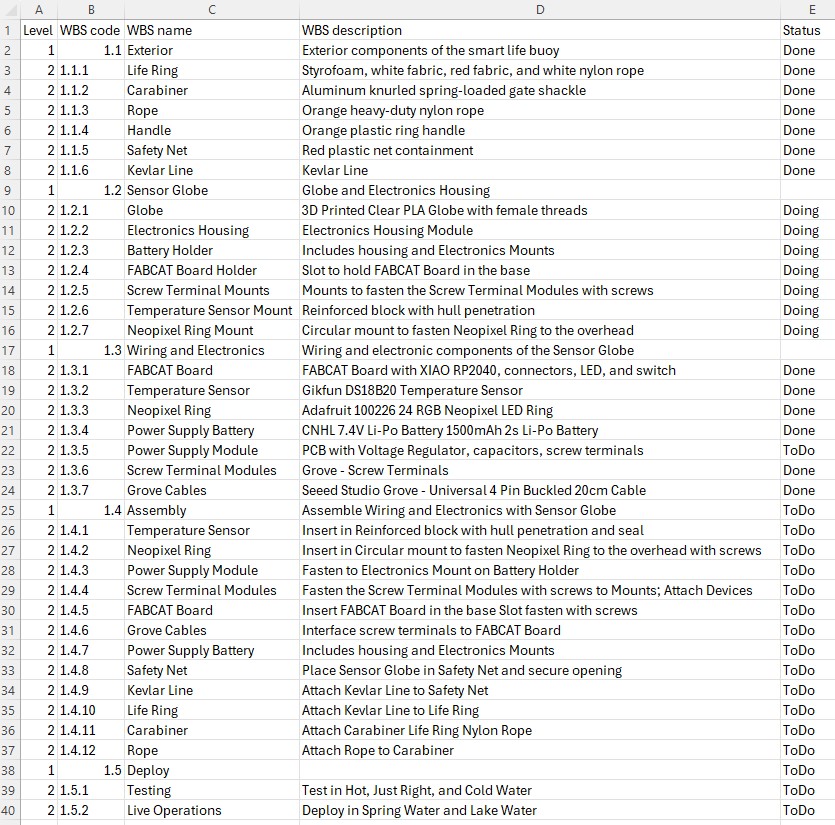
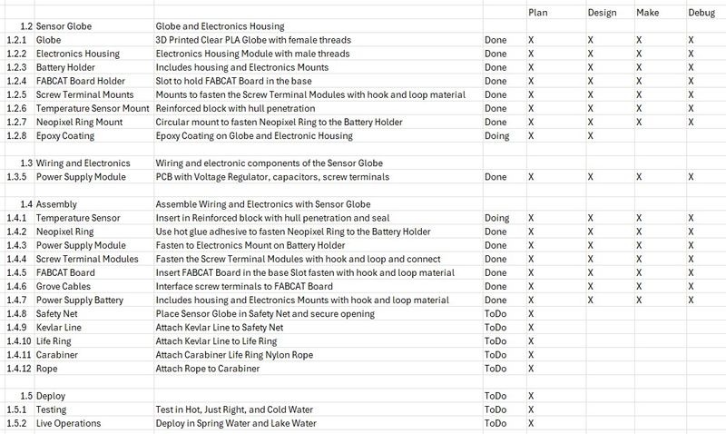
I took the CSV file generated by the WBS and started modifying it. I will need to update the graphic version because I saw a lot of holes and assignments that could be incorporated into the Final Project. I will try to show what I did.
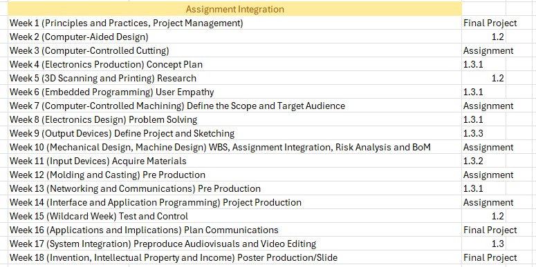
And this table shows the original assignment integration.
Linked from this page to any weeks that you worked on your final project
- Linked from this page to any weeks that you worked on your final project:
There is linkage between the Final Project and all but three of the assignments. The links for each week are in the updated table below
This is the updated table of Assignment Integration
| Assignment Integration | WBS Code |
|---|---|
| Week 1 (Principles and Practices, Project Management) | Final Project |
| Week 2 (Computer-Aided Design) | 1.2 |
| Week 3 (Computer-Controlled Cutting) | 1.2.11 |
| Week 4 (Electronics Production) Concept Plan | 1.3.1 |
| Week 5 (3D Scanning and Printing) Research | 1.2 |
| Week 6 (Embedded Programming) User Empathy | 1.3.1 |
| Week 7 (Computer-Controlled Machining) Define the Scope and Target Audience | Assignment |
| Week 8 (Electronics Design) Problem Solving | 1.3.1 |
| Week 9 (Output Devices) Define Project and Sketching | 1.3.3 |
| Week 10 (Mechanical Design, Machine Design) WBS, Assignment Integration, Risk Analysis and BoM | Assignment |
| Week 11 (Input Devices) Acquire Materials | 1.3.2 |
| Week 12 (Molding and Casting) Pre Production | 1.2.11 |
| Week 13 (Networking and Communications) Pre Production | 1.3.1 |
| Week 14 (Interface and Application Programming) Project Production | Assignment |
| Week 15 (Wildcard Week) Test and Control | 1.2.10 |
| Week 16 (Applications and Implications) Plan Communications | Final Project |
| Week 17 (System Integration) Preproduce Audiovisuals and Video Editing | 1.3 |
| Week 18 (Invention, Intellectual Property and Income) Poster Production/Slide | Final Project |
- What happens if something goes wrong?
Believe me, I have had things go wrong! To be fair, you cannot plan for the unexpected; however, if you know the unexpected will occur, you won’t be so devastated that you just give up when things go wrong. I have not given up and I will continue to adapt and overcome by the Grace of God. It is His strength that keeps me going when the going gets rough. Just keep swimming, swimming, swimming… :)
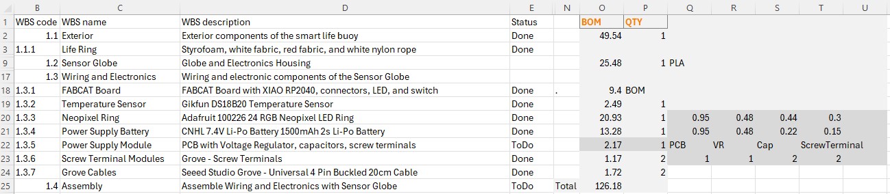
- Bill of Materials - hand in to your local instructors
This is the BoM for the Final Project. Just a word of warning: If you have everything you need in a Fab Lab, this is a realistic number. If you must make a Fab Lab to do this project, like I did, the Bill will be far greater. As I read just this week, “No project was ever completed on time and within budget.” I will try to find the source, but, in my experience, this is a true saying. This statement came from the Risk Analysis and Contingency Plan Guidelines by Sunil Sharma at PMI.org Sharma goes on to say, “Identifying risks associated with a project and mitigating them is a crucial activity of project planning. Managers need to not only analyze project risks, but also must develop contingency plans to address those risks.” I intend to use these guidelines to better understand and mitigate the risks associate with this Final Project.
Included the BOM (Bill of Materials) for your project
- Included the BOM (Bill of Materials) for your project:
| ThermoSphere | Where to buy? | Amount | Price | Total Price |
|---|---|---|---|---|
| 3D PLA filament | Amazon/Prusa Research | 0.1 | 23.99 | $2.40 |
| Polyester film for the decal | Amazon | 0.25 | 22.84 | $5.71 |
| Epoxy resin | Amazon | 0.1 | 59.99 | $6.00 |
| 09-00500 DACRON FABRIC 605 2.97 OZ | AirCraftSpruce.com | 1 | 4.35 | $4.35 |
| Waterproofing beeswax | Locally | 0.1 | 1.97 | $0.20 |
| Snap swivel | Locally | 1 | 0.48 | $0.48 |
| Gikfun DS18B20 Temperature Sensor | Amazon | 1 | 2.49 | $2.49 |
| Adafruit 100226 24 RGB Neopixel LED Ring | Amazon | 1 | 20.93 | $20.93 |
| CNHL 7.4V 1500mAh 2s Li-Po Battery | Amazon | 1 | 13.28 | $13.28 |
| LM1117 5V Voltage Regulator | Digikey | 1 | 0.48 | $0.48 |
| PCB Copper Clad Board uxcell 7X10cm | Amazon | 2 | 0.949 | $1.90 |
| R_1206 | Digikey | 4 | 0.05 | $0.20 |
| LEDFAB1206 | Digikey | 1 | 0.23 | $0.23 |
| Button_Omron_B3SN_6.0x6.0mm | Digikey | 1 | 1 | $1.00 |
| Module_XIAO-RP2040 | Digikey | 1 | 4.68 | $4.68 |
| Conn_PinHeader_1x06_P2.54mm_Horizontal_SMD | Digikey | 1 | 0.6 | $0.60 |
| Conn_PinHeader_1x09_P2.54mm_Horizontal_SMD | Digikey | 1 | 0.9 | $0.90 |
| Conn_PinHeader_2x03_P2.54mm_Vertical_SMD | Digikey | 1 | 0.84 | $0.84 |
| Screw terminal module | Seeed Studio | 2 | 0.15 | $0.30 |
| Capacitors | Digikey | 2 | 0.22 | $0.44 |
| Hook and Loop Tape | Amazon | 0.1 | 17.99 | $1.80 |
| Total | $69.20 |
So when will the WBS be completed? I hope in less than 2 months, but no later than June 5, 2024. This is my schedule right now.
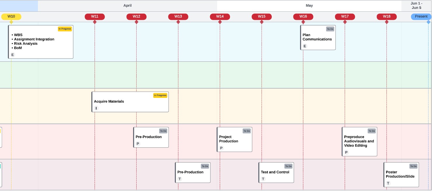
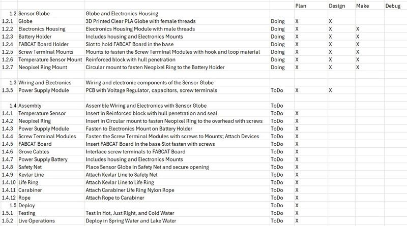
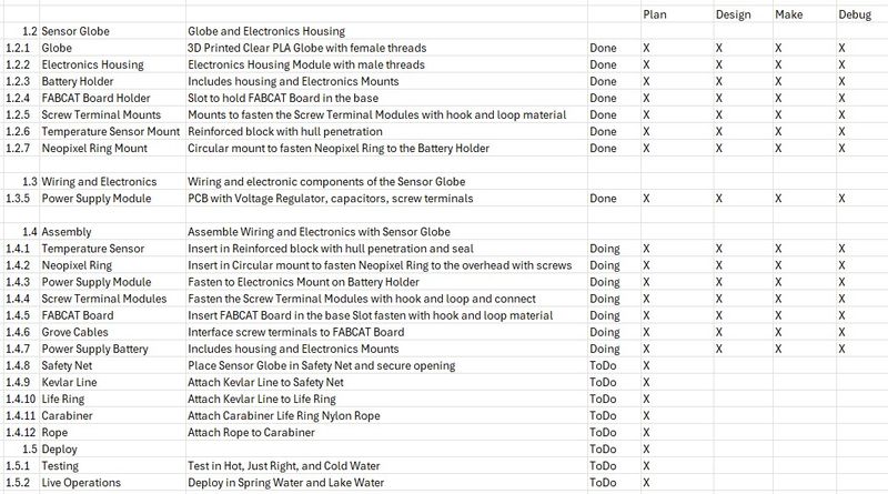
This is a more detailed WBS with the iterations for Plan, Design, Make, and Debug status. I will update this as progress occurs.
W11 Acquire Materials
-
Fab Labs should be provided with all possible materials for students to create their final project. BoM will help for this process to be completed on time.
-
This is the time!
Deliverables
Final Project
- Fab Labs should be provided with all possible materials for students to create their final project
My personal Fab Lab has been in the process of being fully stocked with the inventory required to successfully complete the Fab Academy. It has been a great undertaking as an individual without external funding, but I will say it is doable if managed properly.
- BoM will help for this process to be completed on time
The BoM was documented in the W10 section and the materials are on hand in my personal Fab Lab.
- This is the time!
This is an exciting time! I hope you enjoy the ride :) Here we go!
This is the WBS status as of Week 11. Slightly ahead of schedule!
W12-W13 Pre-Production
-
Based on their schedule students can start producing some of the parts of their project and test the concepts you had for it.
-
It’s About Continuous Testing & Managing wisely your resources (time, materials, effort).
Deliverables
Final Project
- Based on their schedule students can start producing some of the parts of their project and test the concepts you had for it
We are well into the second half of Fab Academy and I feel confident about the whole process of learning in this environment. The two most difficult parts for me has been design and documentation; I am more confident in both of these areas and I can see the finish line.
This cycle I have been blessed with wonderful Instructors, all of the required inventory, and plenty of time to explore this learning space.
As you can see, I have already begun making parts of my project and testing the concepts I have incorporated into the Final Project. The heart of the project is the FABCAT board and I am confident that it can perform as imagined. I have also completed most of the designs for the rest of the parts and will be making them soon.
- It’s About Continuous Testing & Managing wisely your resources (time, materials, effort)
As you have seen in the previous sections, I have been diligently testing the concepts of the Final Project while managing the time, materials, and effort required to be successful. I will continue to be disciplined in these areas with the guidance of my Instructors who have been so helpful.
With the Design for the Electronics Holder complete, it is time to Make. This will be a Pre-Production/Prototype run to verify that the Design was correct and Debug if necessary.
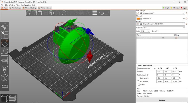
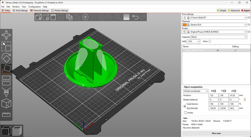
The 3D printing required exporting the model designed in Fusion 360 to a STL format, then importing it into PrusaSlicer. Since this has been practiced many times before, I was fairly comfortable with the process. I still learned a bit more. When I imported the STL into PrusaSlicer, the model was on its side.
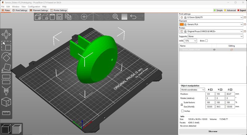
I used the Rotate tool and the widget to rotate the model as close to 90 degrees as I could get it. There is not a method to type the value in, so using the mouse was the best I could do. I got it to 90.03 and thought that was good enough.
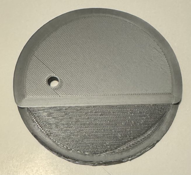
The small difference caused the model to be slightly off the plane and made a separation in the base. This was puzzling to me, but I went with it and figured it would work out. I exported the g-code and tried to print. This is what the bottom looked like.
And this is the top.
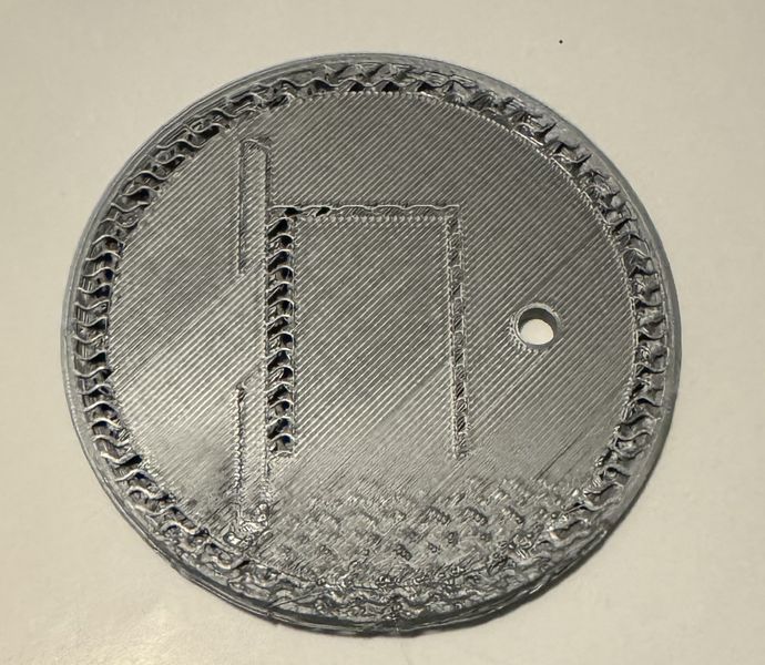
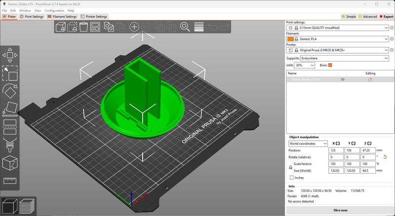
The edge lifted up so much that it caused the first crash I have had on my Prusa 3D printer. I stopped the print and went back to the design. The design was still the same and I changed the orientation of one of the models thinking that was the problem. It still came into PrusaSlicer on its side. But this time I decided to use “Place on face”.
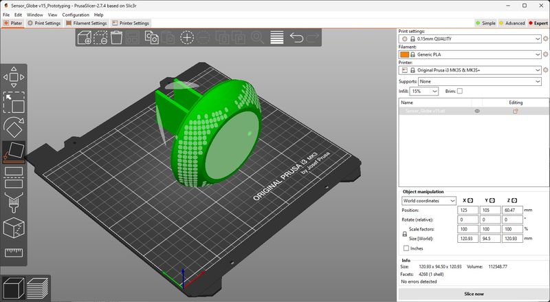
As soon as I clicked on the base face, it rotated to the perfect position.
I exported the model with the same settings, but this time I added supports everywhere. (Just to be safe :)
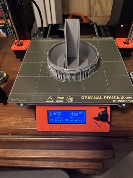
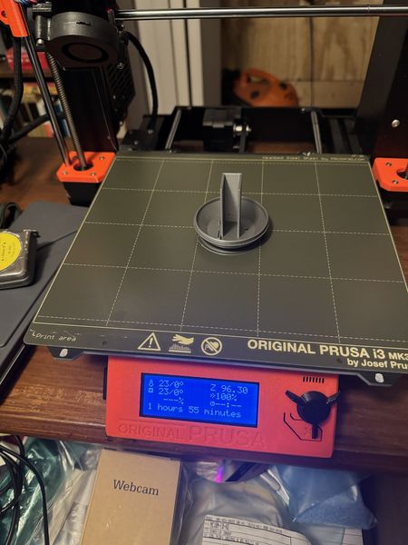
The print job took 11.5 hours, but it was worth the wait.
I wanted to make sure the prototype had the proper dimensions.
Perfect fit! Now for the post-processing :)
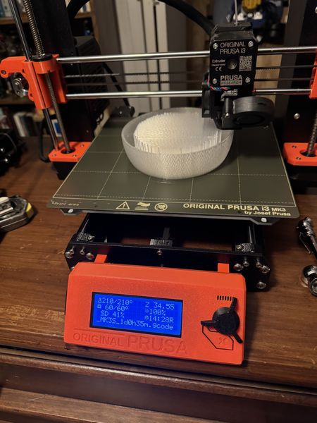
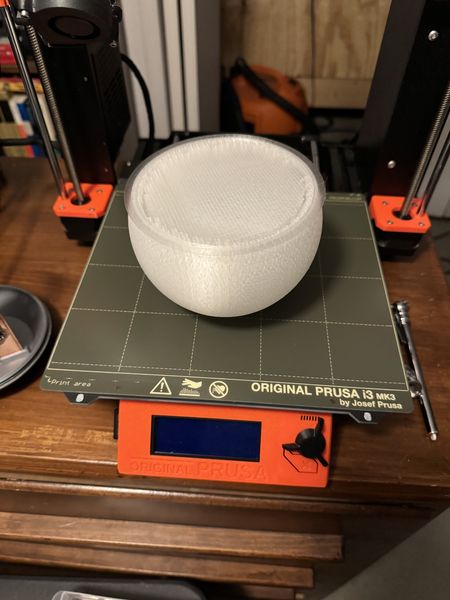
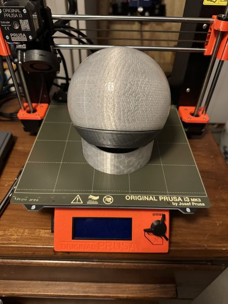
The next print job was the globe. I imported it the same as the Electronics Housing. I oriented it in the upward position and chose supports everywhere. I exported the g-code and it said it would take 24.5 hours. I started it Friday night and on Saturday morning I decided to listen to it while I probed analog and digital devices. What an enjoyable experience :) This is what I found in the morning.
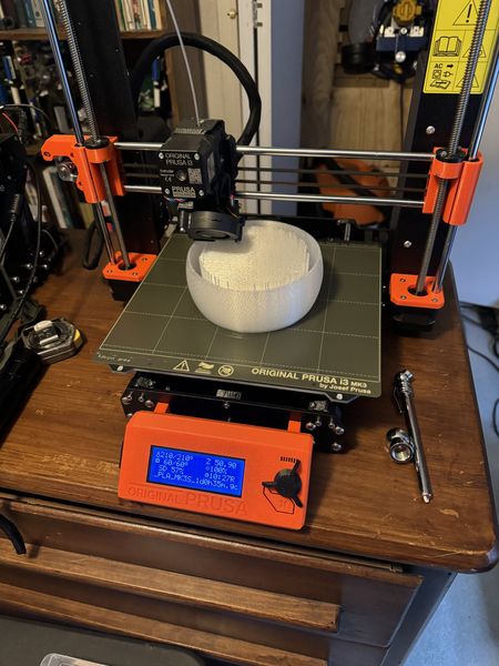
A little bit later. Looking pretty cool!
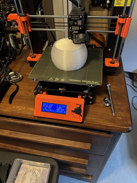
Almost there!
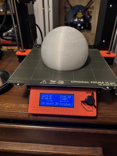
Would you look at that!
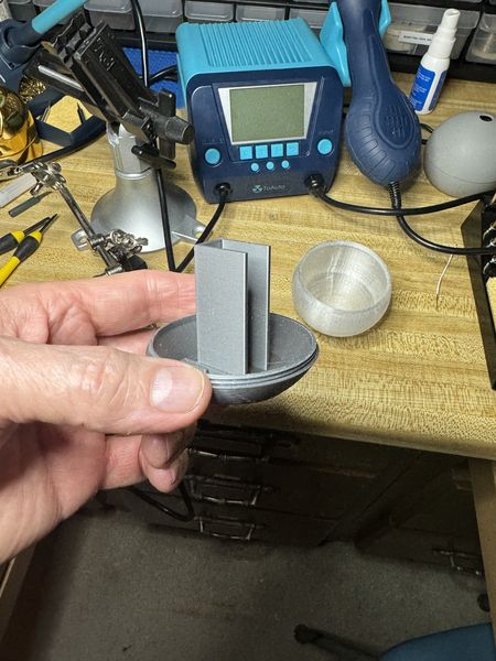
Post-processing was a very rewarding experience. Here is the globe parted from the 3D printer.
This after I cut around the edges.
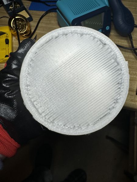
I pulled the support out of the globe and here is a good picture.
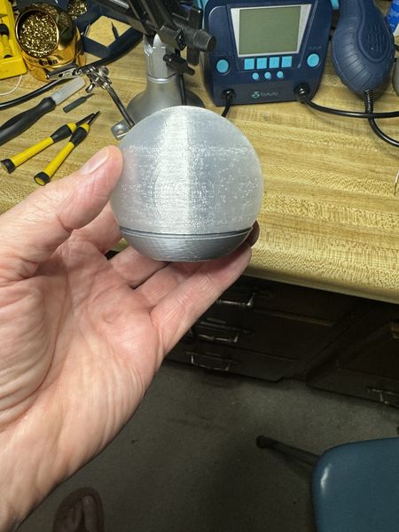
Perfect fit!
In addition to the 3D print jobs shown here, there were other print jobs that happened for the production of the Stand and Stand Adapter in Wildcard Week.
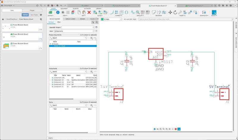
While I was waiting on the print job, I worked on designing the Power Supply Module… This seemed like a simple task since I had designed more complex boards. To be safe, I did some research on the Internet. I found some good help from LM1117 Linear Voltage Regulator by AaronPrice. I didn’t need a variable power supply, but this was a nice Instructable. Since there were so few parts, I decided to design in the Fusion 360 app. This was no small feat, but it all turned out well. This is my schematic.
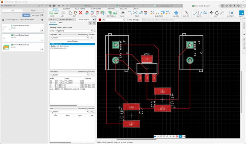
This is my board.
I used my documentation from Electronics Design to refresh my memory.
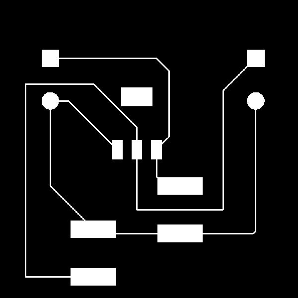
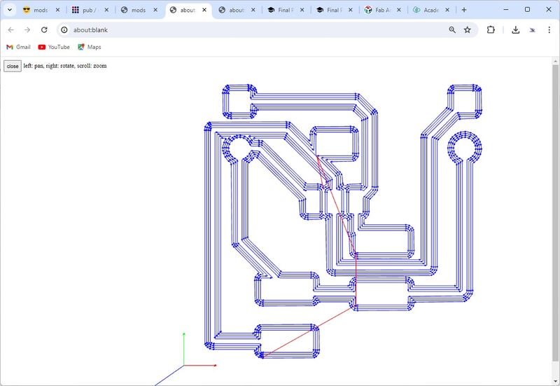
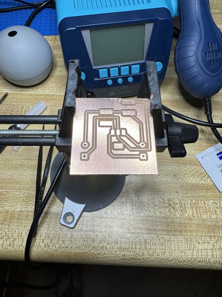
First, I save the Fusion 360 project as an Eagle 9.x format as I described in Electronics Design and exported the trace image, drills, and border for GIMP. After cropping them to the proper size, this is what I sent to mods.
The trace image.
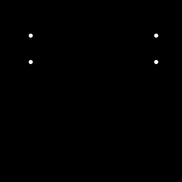
Drill holes for the through-hole screw terminals.
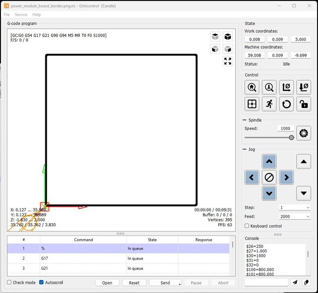
And border to cut out the board.

I used mods old index to generate the G-code from mill 2D PCB png.
The trace image.
Drill holes for the through-hole screw terminals.
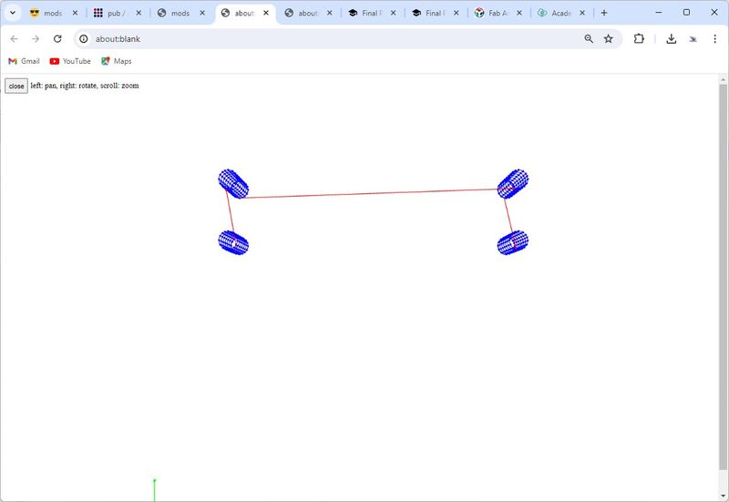
And border to cut out the board.

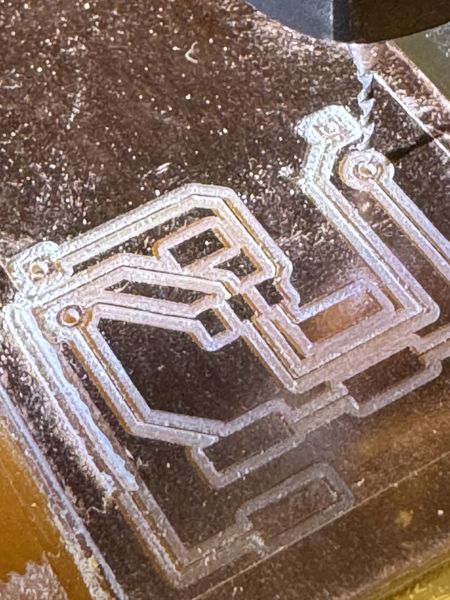
Now I need to mill the Power Supply Module board. Thankfully, I already had my FR-1 mounted from my last job. I pressed down on the material to make the tape stick again and I taped around the edges for extra protection. I only had 37mm wide material left and the board required just that. I wanted to run the traces first to be sure I had enough room.
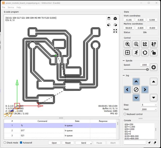
First, I raised the endmill and zeroed Z to cut air and figure out if it would fit. It was just big enough :)
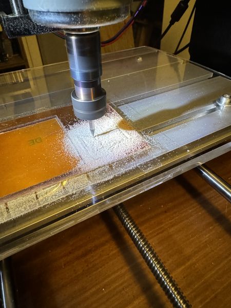
Then I drilled the holes using this g-code.
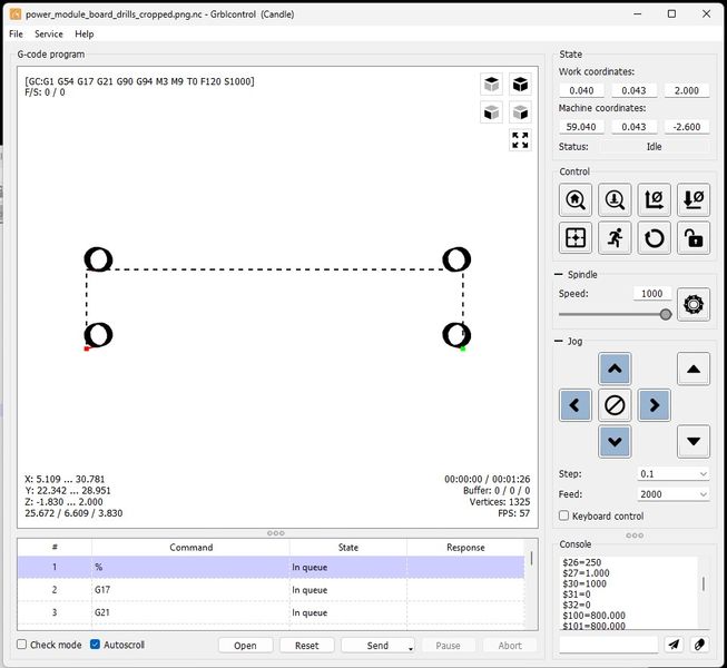
Again, I cut air, and I am so glad I did. When I designed the board I used vias to make the holes. I had never designed through-holes, so this was a first. I’m glad I was cautious. Although they were in the right place, they were way too big. My solution was to operate the CNC using the Candle interface to position the endmill (using the g-code generated image). I changed the endmill to 1mm since the posts on the screw terminals were 0.95mm and drilled each hole to a depth of 1.8mm at 0.1mm increments. Kind of a hack, but it worked beautifully. The posts were 5mm apart and it was so cool to use the machine with precision.
This is the border for cutting out the board.
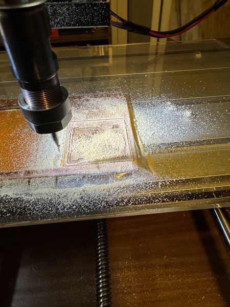
I ran the jog, but I was a little nervous about the tape holding, so I kept my finger on the mouse to abort if necessary. I’m glad I did, because the board popped up a little on the last round and I aborted. It made it successfully.
I cleaned the board to prepare it for stuffing. The traces were real thin, so I was nervous, but they all survived.
This is the electronics side stuffed. The capacitors were a surprise. I thought I was using 1206, but the pads were huge and too far apart. I had selected the wrong capacitor footprint in Fusion 360. It was from the Fab inventory, but not the one I wanted. All I had in this size footprint was a 100uF electrolytic capacitor. I did some research and found someone who used a 100uF electrolytic capacitor for a LM1117 circuit and it worked just fine, so I did the same. I’ll tell you what; these are not fun to solder. The base is plastic and it melts when touched with the solder iron. A very delicate process! But I got it done; although it was a little messy :)
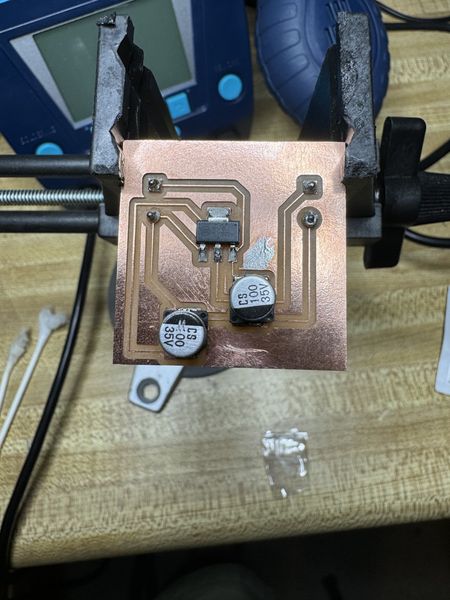
Then I soldered the screw terminals in the through-holes. I used clear tape to hold them in place while I soldered the and it worked fine.
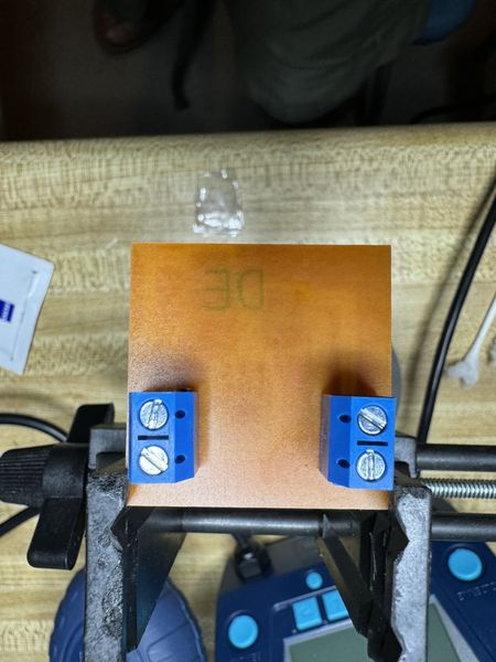
I cleaned up the board with cotton swabs and alcohol, then brushed off the cotton fibers that remained.
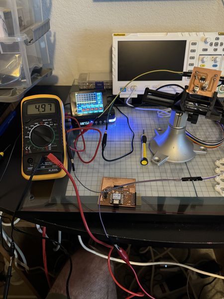
Now for testing! It was getting late, but I just had to see this board working. It was the first of its kind for me and I was pretty excited. I should have taken pictures, but I was on an adventure of discovery. I connected my MDP-P905 digital power supply to the input and connected my multimeter to the output. I set the input to the 7.4V setting for the battery I planned to use and set the current to 1A since that was the fuse I plan to use. When I applied power, the voltage input was good and the current settled at 35mA. However the output was fluctuating and various voltages up to 8V and thereabouts. I had a faulty circuit somewhere. I used my multimeter to trace from the input to the output and found the faulty trace that was the ground wire to the input capacitor. This is after I fixed it, but you can see the missing piece of the trace.
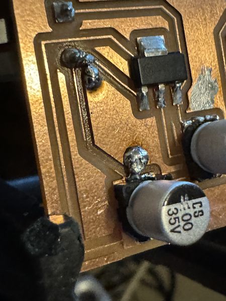
Long story short, I thought it vaporized, but it was done by me when I cleaned the board. After bridging the solder and testing, the power supply module worked and powered up my FABCAT board.
This is the setup to test the power supply module. You can see the output on the multimeter.
This shows the output of the digital power supply.
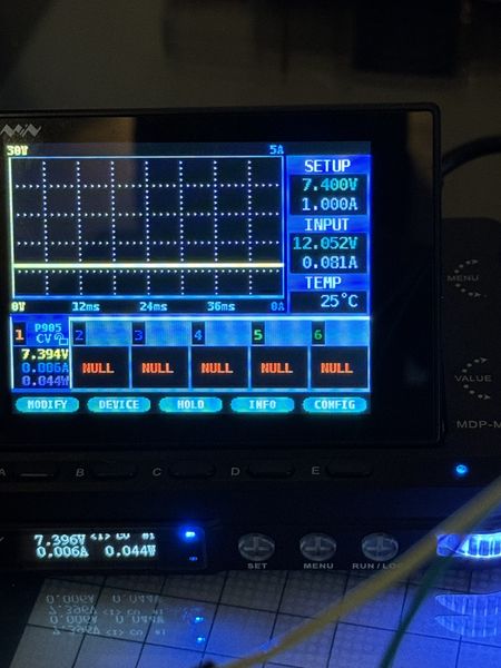
This is a video of powering up the FABCAT board with the digital power supply.
Now I have a power supply to prototype the Final Project :)
The next step is to install the hardware in Electronics Housing. The simplest way I could think of and still look acceptable was to use hook and loop material with adhesive on one side. Here’s the sketch and where the material will go.
Hook applied.
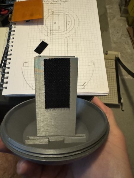
Loop applied.
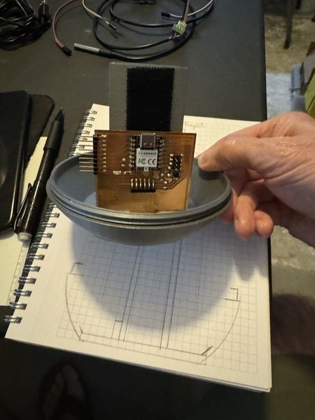
FABCAT Board attached.
Power supply loop.
Power supply attached.
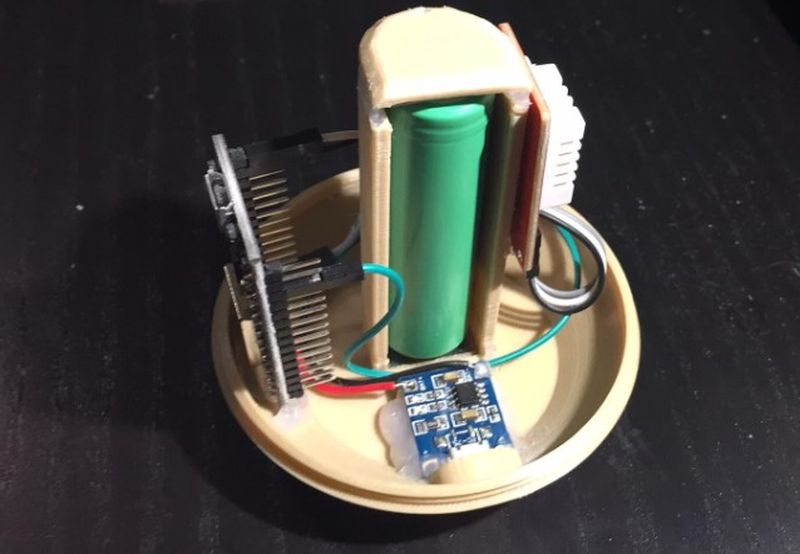
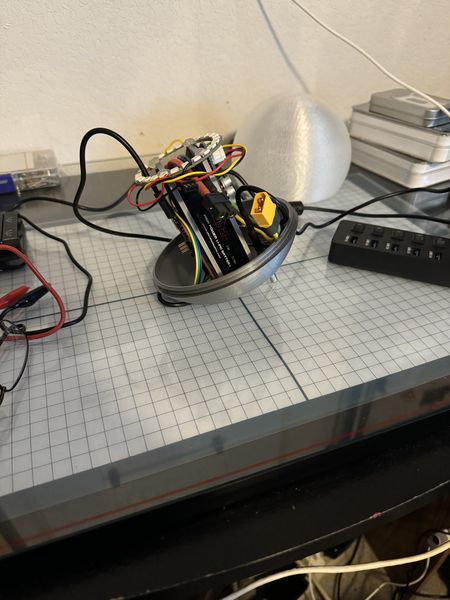
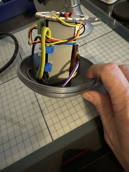
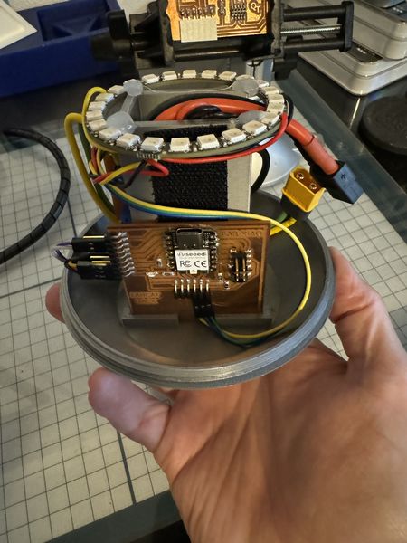
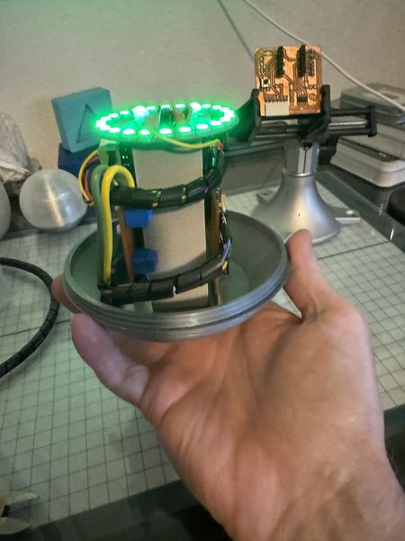
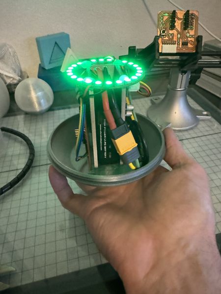
Here’s a few shots after assembly.
![]()
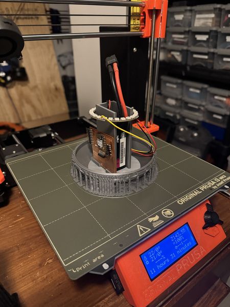
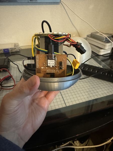
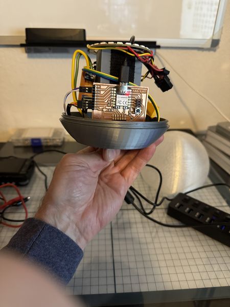
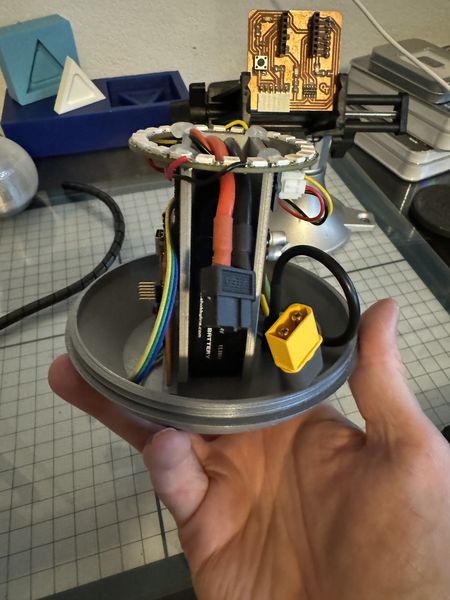
Now that the hardware is installed, I need to apply battery power and test the FABCAT board operating on the onboard battery. This is an image of the Electronics Housing operating on battery power.
The next step is to program the FABCAT using the USB-C connection. To do this I must disconnect the battery. While I do this, I will add some hook and loop inside the Battery Holder to hold the battery in place during operation.
This will hold the battery in place.
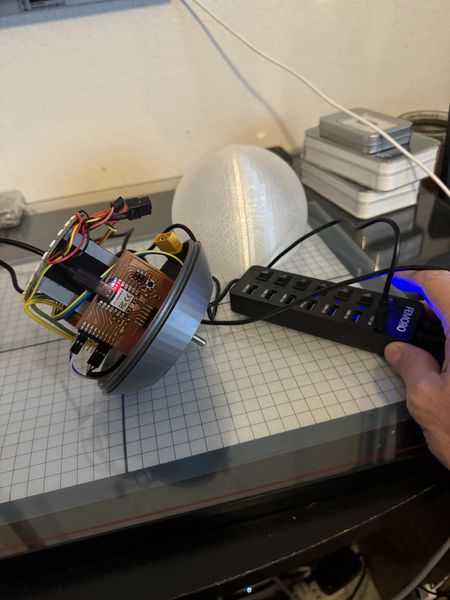
With the battery secured and disconnected, I will plug in the USB-C connector to the FABCAT board to connect to the computer.
Then I turn on the USB hub to connect to the computer.
To follow the order of testing from before, I will upload the temperature sensor program using Thonny.
# Rui Santos & Sara Santos - Random Nerd Tutorials
# Complete project details at https://RandomNerdTutorials.com/raspberry-pi-pico-w-micropython-ebook/
# Modified by Jim Hart 4/1/2024

import machine, onewire, ds18x20, time

# Pin configuration for DS18B20 temperature sensor
ds_pin = machine.Pin(29)

# Create DS18X20 object using OneWire protocol with specified pin
ds_sensor = ds18x20.DS18X20(onewire.OneWire(ds_pin))

def celsius_to_fahrenheit(temp_celsius):
    # Convert temperature from Celsius to Fahrenheit
    temp_fahrenheit = temp_celsius * (9/5) + 32
    return temp_fahrenheit

# Scan for DS18B20 sensors and print their ROM addresses
roms = ds_sensor.scan()
print('Found DS devices: ', roms)

while True:
    # Initiate temperature conversion for all sensors
    ds_sensor.convert_temp()
    time.sleep_ms(750)  # Wait for the conversion to complete (750 ms is recommended)

    for rom in roms:
        print(rom)

        # Read temperature in Celsius from the sensor
        temp_c = ds_sensor.read_temp(rom)

        # Convert Celsius temperature to Fahrenheit
        temp_f = celsius_to_fahrenheit(temp_c)

        # Print the temperature readings
        print('temperature (ºC):', "{:.2f}".format(temp_c))
        print('temperature (ºF):', "{:.2f}".format(temp_f))
        print()

    time.sleep(5)  # Wait for 5 seconds before taking readings again
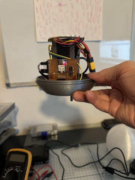
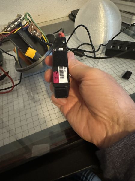
I am holding the buoy by the temperature sensor.
This screenshot shows the temperature rising.
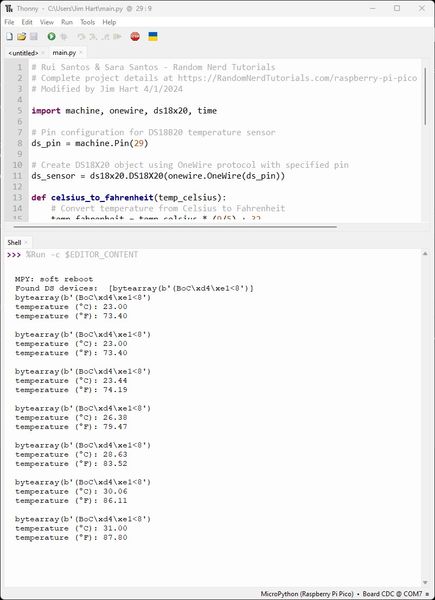
This concludes the temperature test of the Smart Ring Buoy.
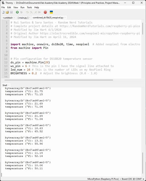
To contnue the order of testing from before, I will upload a neopixel program using Thonny. This neopixel ring program was written for the NeoPixel WS2812B RGB LED with Raspberry Pi Pico (MicroPython). Since I am using a 24 LED Neopixel Ring and the XIAO RP2040, I will make the changes necessary and document the changes.
# Original Author https://electrocredible.com/neopixel-micropython-raspberry-pi-pico-ws2812b/
# Modified by Jim Hart on April 16, 2024

import neopixel
from machine import Pin
import time

ws_pin = 6 # This is the pin I have the signal line attached to
led_num = 24 # This is the number of LEDs on my NeoPixel Ring
BRIGHTNESS = 0.2  # Adjust the brightness (0.0 - 1.0)

neoRing = neopixel.NeoPixel(Pin(ws_pin), led_num)

def set_brightness(color):
    r, g, b = color
    r = int(r * BRIGHTNESS)
    g = int(g * BRIGHTNESS)
    b = int(b * BRIGHTNESS)
    return (r, g, b)

def loop():
    # Display red
    color = (255, 0, 0)  # Red color
    color = set_brightness(color)
    neoRing.fill(color)
    neoRing.write()
    time.sleep(1)

    # Display green
    color = (0, 255, 0)  # Green color
    color = set_brightness(color)
    neoRing.fill(color)
    neoRing.write()
    time.sleep(1)

    # Display blue
    color = (0, 0, 255)  # Blue color
    color = set_brightness(color)
    neoRing.fill(color)
    neoRing.write()
    time.sleep(1)

while True:
    loop()
This is the Thonny IDE.
![]()
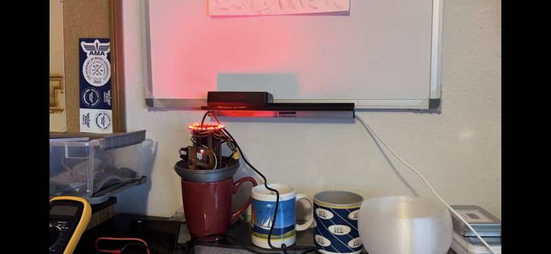
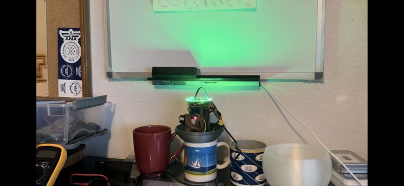
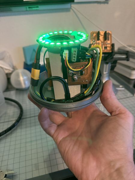
You can see the NeoPixel Ring operating in Red.
![]()
You can see the NeoPixel Ring operating in Green on Battery Power.
![]()
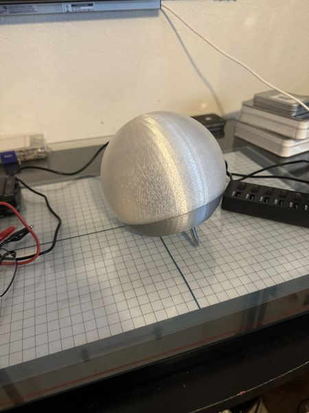
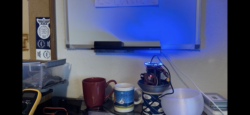
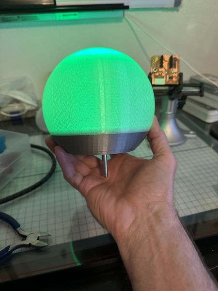
You can see the NeoPixel Ring operating in Blue on Battery Power with the Globe on.
![]()
This concludes the test of the NeoPixel Ring in the Smart Ring Buoy, now on to making them work together :)
This is the WBS status going into Week 12. Pre-Production is well on its way!
Since this is also Molding and Casting week, I will work on 1.2.8 Epoxy Coating while I continue with testing the programming and electronics.
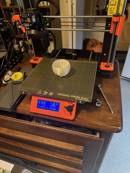
My first task is to print a prototype (50% scale) of the Globe and Electronics Housing. Note: I am printing the Globe upside down per my Instructor Pablo’s recommendation. At 50% scale it will only take 3.1 hours to print. This will allow me to test the Marine Epoxy Resin that I intend to coat the Globe and Electronics Housing with.
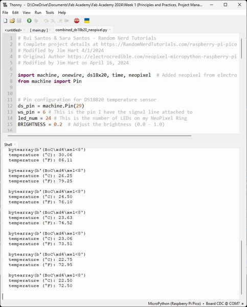
While I wait for the print job, I will work on combining the temperature sensing and NeoPixel Ring output programming.
I combined the two programs above into a single program. I also used the code from the aduino program I used to test the NeoPixel Ring previously.
# Rui Santos & Sara Santos - Random Nerd Tutorials
# Complete project details at https://RandomNerdTutorials.com/raspberry-pi-pico-w-micropython-ebook/
# Modified by Jim Hart 4/1/2024
# Original Author https://electrocredible.com/neopixel-micropython-raspberry-pi-pico-ws2812b/
# Modified by Jim Hart on April 17, 2024

import machine, onewire, ds18x20, time, neopixel  # Added neopixel from electrocredible
from machine import Pin


# Pin configuration for DS18B20 temperature sensor
ds_pin = machine.Pin(29)
ws_pin = 6 # This is the pin I have the signal line attached to
led_num = 24 # This is the number of LEDs on my NeoPixel Ring
BRIGHTNESS = 0.2  # Adjust the brightness (0.0 - 1.0)

# Create DS18X20 object using OneWire protocol with specified pin
ds_sensor = ds18x20.DS18X20(onewire.OneWire(ds_pin))

# Create an instance of the NeoPixel class called neoRing
neoRing = neopixel.NeoPixel(Pin(ws_pin), led_num)

def celsius_to_fahrenheit(temp_celsius):
    # Convert temperature from Celsius to Fahrenheit
    temp_fahrenheit = temp_celsius * (9/5) + 32
    return temp_fahrenheit

def set_brightness(color):
    r, g, b = color
    r = int(r * BRIGHTNESS)
    g = int(g * BRIGHTNESS)
    b = int(b * BRIGHTNESS)
    return (r, g, b)

# Scan for DS18B20 sensors and print their ROM addresses
roms = ds_sensor.scan()
print('Found DS devices: ', roms)

while True:
    # Initiate temperature conversion for all sensors
    ds_sensor.convert_temp()
    time.sleep_ms(750)  # Wait for the conversion to complete (750 ms is recommended)

    for rom in roms:
        print(rom)

        # Read temperature in Celsius from the sensor
        tempC = ds_sensor.read_temp(rom)

        # Convert Celsius temperature to Fahrenheit
        tempF = celsius_to_fahrenheit(tempC)

        # Print the temperature readings
        print('temperature (ºC):', "{:.2f}".format(tempC))
        print('temperature (ºF):', "{:.2f}".format(tempF))
        print()

    time.sleep(5)  # Wait for 5 seconds before taking readings again
    # delay(1000);   # I put this in the loop because it was going too fast to observe
    if (tempF < 65): #{ # I selected this temperature since the ambient temperature is about 73 degrees
    # color(255,255,0); // turn the RGB LED blue
    # delay(1000); // delay for 1 second
    # Display blue
        color = (0, 0, 255)  # Blue color
        color = set_brightness(color)
        neoRing.fill(color)
        neoRing.write()
        time.sleep(1)
    #}
    elif (tempF > 75 and tempF < 85): #{ # I selected these temperatures since they are in the middle
    # color(255,0,255); // turn the RGB LED green
    # delay(1000); // delay for 1 second
    # Display green
        color = (0, 255, 0)  # Green color
        color = set_brightness(color)
        neoRing.fill(color)
        neoRing.write()
        time.sleep(1)
    #}
    elif (tempF > 85): #{ # I selected this temperature since it is below the temperature of my maximum 85 degrees
    # color(0,255,255); // turn the RGB LED red
    # delay(1000); // delay for 1 second
    # Display red
        color = (255, 0, 0)  # Red color
        color = set_brightness(color)
        neoRing.fill(color)
        neoRing.write()
        time.sleep(1)
    #}
I have not programmed in MicroPython much, so I had a few things to learn. The comments use a “#” rather than a “//”. The IF-THEN-ELSE is now ELIF and a “:” after the “(expression) rather than braces. MicroPython is also picky about indentation. After several iterations I had it working in the form above :)
The program must be saved as main.py to the RP2040 in order for it to run on powerup.
Now I need to test the input-processing-output. I don’t have remote read capability yet. That will be another spiral. However, I can connect to the USB-C connection on the RP2040 and watch the serial monitor output during operation.
This is the serial output while in hot water.

This is the NeoPixel Ring properly displaying red.
This is the serial output while in just right water.
This is the NeoPixel Ring properly displaying green.
This is the serial output while in cold water.
This is the NeoPixel Ring properly displaying blue.
Now I will unplug the USB-C cable, connect the battery, screw on the globe, and test the Smart Buoy.
The other test I need to do is check the power usage of the Smart Buoy while it is operating at the battery voltage. This is my setup with the digital power supply connected to the power connector.
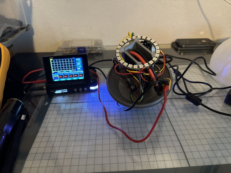
This is a closeup so you can see the settings.
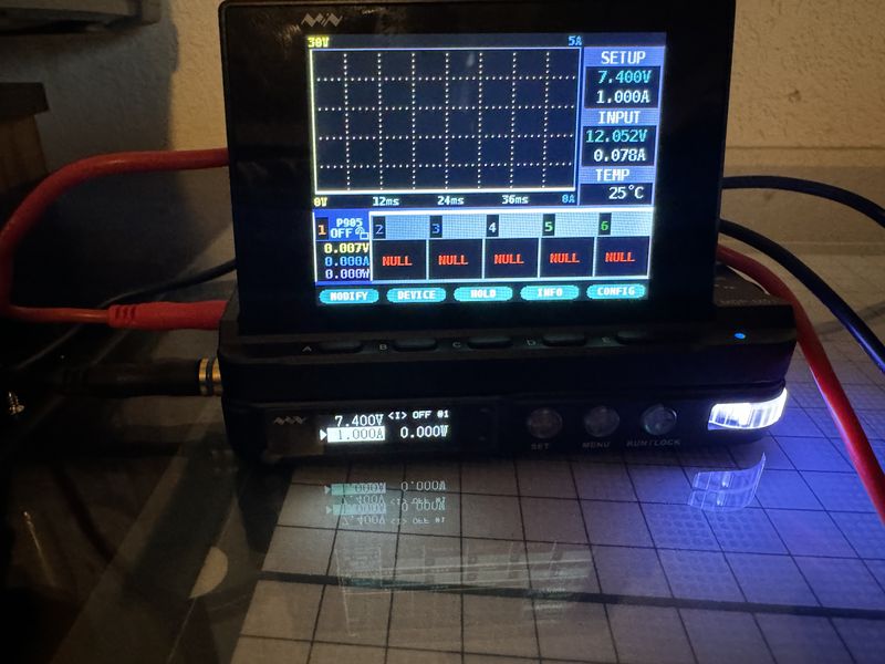
This is a video of the test so you can see the results.
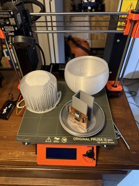
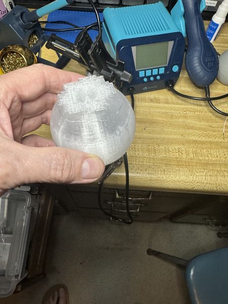
The prototype of the Globe and Electronics Housing finished printing, so I will document that here. This is the Globe when it finished printing.
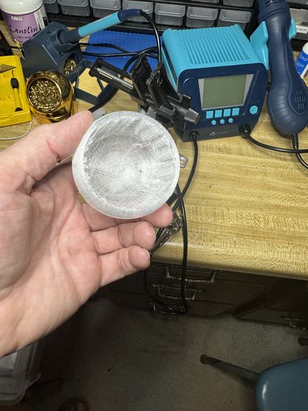
The Globe parted from the 3D printer.
The Globe supports on the inside.
The Electronics Housing when it finished printing.
The Electronics Housing parted from the 3D printer with the post-processed Globe in the back.
They assembled easily just like the full size Smart Buoy.
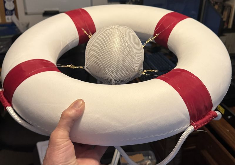
With life and weather preventing, I have not applied marine epoxy to the prototype, but I did make progress toward the safety net this week. My idea is to suspend the smart buoy in a safety net within the life ring. Using my fishing and sailor experience, I decided a fish net would work. This provides support while giving limited access to the water. (I’m not too sure about tossing this project into the water without a safety net ;) I purchased a net and had some basting tape from sailmaking.

I also purchased some twine for this project. This is the twine fixed to the net using basting tape.

I wanted some strong thread to sew the twine to the net, so I purchased some Big Game Braid. This is an image of the sewn on twine.

Next I sewed the hook and loop material to the net and twine. I also placed some loop material on the bottom of the smart buoy to hold the net in place.

This is an image with two ends of the net fixed with hook and loop material.

This is an image with four ends of the net fixed with hook and loop material.

This is a top view with the net fixed in place on the smart buoy.

This is the WBS status going into Week 14. Time for Project Production! I should be finishing up all but Test and Control this week.

W14 Project Production
-
A Milestone!
-
Integrate all the parts so that your ideas start materializing, this will be very helpful for future tasks.
Deliverables
Final Project
- A Milestone!
This truly is a Milestone! Not only is the Final Project fully functional, by following the guidance of the content related to Managing Projects as presented by Norella Coronell and May El-Dardiry, this Final Project is on time and within a reasonable budget for a Personal Fab Lab.
- Integrate all the parts so that your ideas start materializing, this will be very helpful for future tasks.
Documented how you implemented system integration in your final project
- Documented how you implemented system integration in your final project:
During this week, I got a little jump on the upcoming System Integration Week by organizing the wires in the Smart Buoy by using wire management.
Here are some images before wire management.
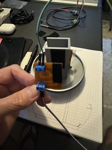
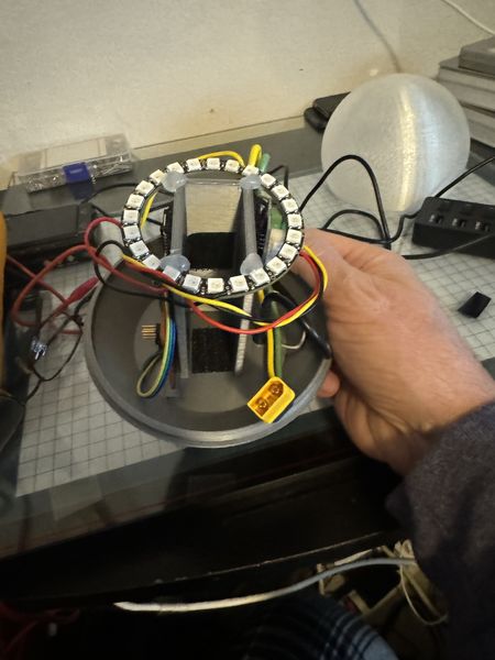
This is the Power Supply Module and the Grove - Screw Terminal Module for the NeoPixwl LED Ring.
This is an empty side showing the back of the Power Supply Module and a “tangle of wires”.
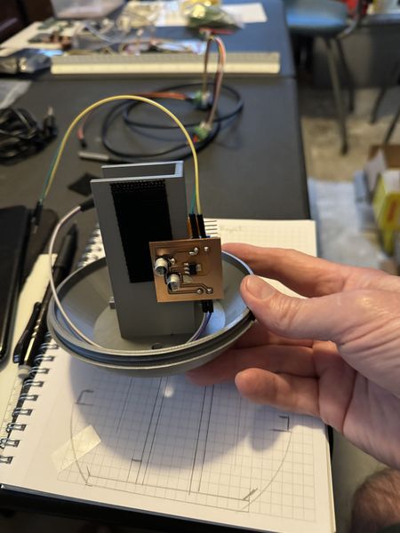
This is the side with the FABCAT Board and more wires.
This is the side for Battery Holder access.
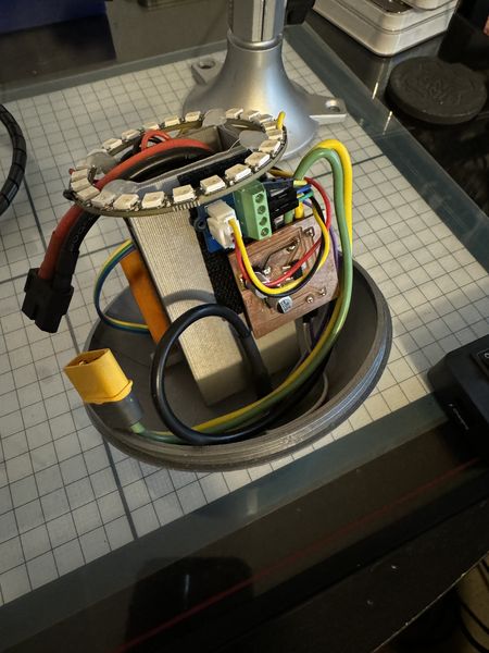
I used the wire management coils that came with my MakerMade CNC500. I had extra so they came in handy. These are images after installing wire management and verifying proper operation.

This is the WBS status going into Week 15. This is the week for Test and Control and that has been completed. I will focus on the Wildcard Week assignment this week.

W15 Test and Control
-
The product/system should at least work.
-
Students should test and and control variables in order to make it work.
Deliverables:
- The product/system should at least work.
Using Design Thinking as presented by Interaction Design Foundation, I have iteratively designed from an idea while empathizing from a user’s perspective, prototyped, tested, as I defined what the end product would be and do. The product/system has worked for some time now, this was built into the design process and my way of working.
- Students should test and and control variables in order to make it work.
I frequently used known working systems to test ideas and then applied the concept to the prototype being developed. This allowed me to see how a working system should respond and then allowed me to fail early without becoming frustrated because I didn’t know what I didn’t know. In other words, I knew what to expect in a working system and this made a benchmark to test against.
Placed Sensor Globe in Safety Net and secured opening; Attached Nylon Line to Safety Net using Snap Swivels; and Attached Nylon Line to Life Ring using Snap Swivels. The Final Project is now a Smart Ring Buoy!
The safety net is there to mitigate the risk of losing the Smart Buoy in the initial stages of operation. There is a possibility of leakage as well as a possibilty of being carried down the river :) Although I could make another one, I will run out of time in doing so. This gives me confidence in tossing my Final Project into the water. As in swimming, you need to know how to tread water before you swim.
There is not much digital fabrication in the above iteration in the Final Project; in fact, I did not use a computer. I used my experience in fishing with my Grampy and the materials I have acquired in my previous fishing adventures. My Grampy taught me how to tie a fisherman’s knot. I was trying to use Trilene Big Game Braid I showed above for the sewing, but I could not get it to cooperate in my fingers. Nylon fishing line does not fray like the braid did, so I thought I would dig up my old fishing line. I have a surf-casting rod and reel in the garage, so I used that line. It worked perfectly and I like that it is clear and barely visible. So that’s what I’m going with for now.
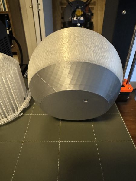
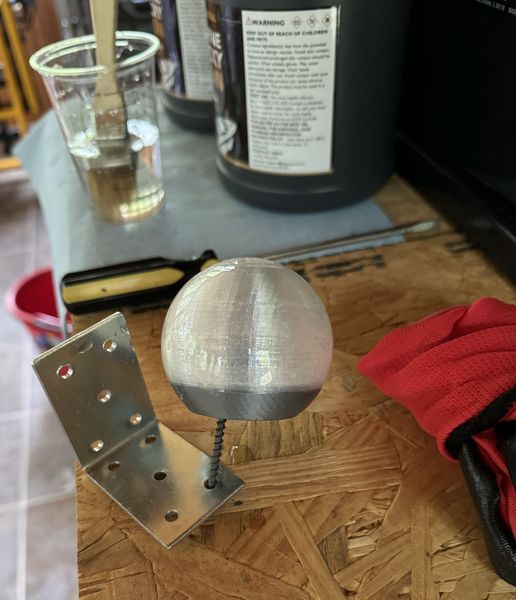
This is Wildcard Week and I have chosen Composites as my topic for the assignment. This fits perfectly into the need to waterproof the Final Project. I became familiar with the process and tested how the resin would go onto the PLA I used for the Sensor Globe and the Electronics Housing. I wanted to use the prototype I showed above just in case I had problems. I’m so glad I did. I coated the Smart Buoy Prototype with Marine Epoxy. It was perfectly glassy and will work wonderfully on the Final Project. I did not separate the globe from the electronics holder while coating it since I held it with a screw in the bottom; it cured like that. I am not able to open it due to the epoxy seeping into the threads. I will definitely be keeping the actual Smart Buoy separated during coating. I even tried to chisel out the epoxy to break the threads loose. Nope! The epoxy is doing what it is made for and won’t give up without ruining the part.
This is my setup for applying the resin.
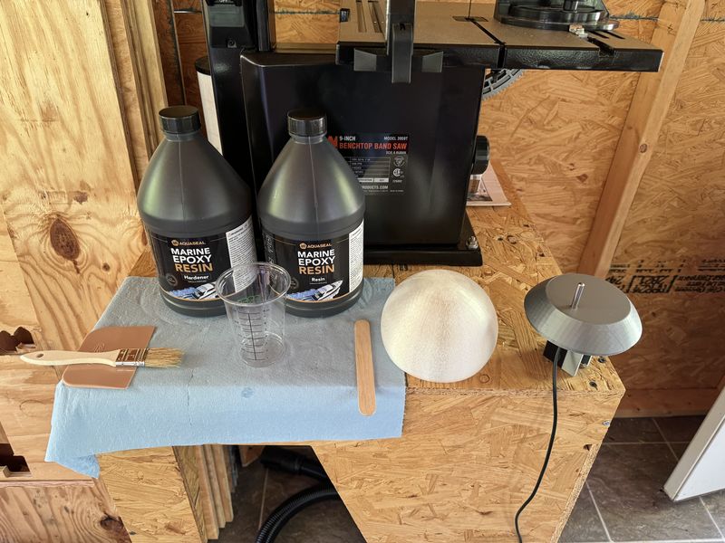
This is after the resin was mixed for 3 minutes, just before application.
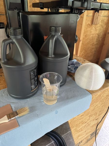
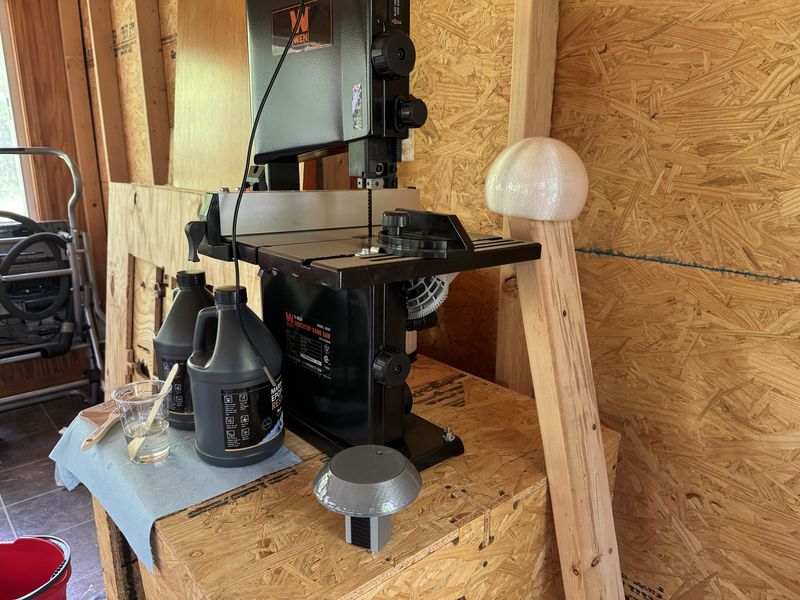
This is after application and the parts are curing.
I coated the edges and the threads to ensure waterproofing. Once they were cured, I try to thread them together. They did not fit! I waited a day and began removing some epoxy little by little (using proper PPE of course). It took a lot of post-processing, but I made them fit again :)
In order to mitigate the risk of damaging the electronics during the resin coating process, I thought I should remove the electronics until the Sensor Globe and Electronics Housing cured. Turns out this was a good choice since I had to post-process the parts to restore proper fit. Now that the parts fit again, I need to re-integrate the electronics with the structural components. I took this opportunity to do a photo shoot of the individual components to demonstrate System Integration.
W16 Plan Communications
-
2 things are required from the student: Slide and Video.
-
Planning especially around audiovisual will help create a nice piece.
-
Why, who, when, where, what and HOW!
Deliverables:
- 2 things are required from the student: Slide and Video.
During the last cycle I produced a Slide with the intention of finishing, so I had a head start on this piece. Although my Final Project has changed, this gives me somewhere to start. I typically need a starting point or something that provides scaffolding that I can flesh out. This is what I started with.
As you can see, this is outdated, but it was a place to start. I have not made many videos, so this is new territory. Most of my videos are from my iPhone and short. I have learned to make the landscape layout and process it with ffmpeg, but that’s about it.
- Planning especially around audiovisual will help create a nice piece.
My Instructor Adrian told me to plan an audiovisual that was 1 minute long. 20 seconds of “Stating the Problem”, 20 seconds of “Showing the Process”, and 20 seconds of “Showing the Solution”. I spoke with my Son-In-Law about video editing. He makes YouTube videos all the time to show what he is doing on the mission field. In just a few minutes he showed me how to use iMovie on my iPhone. I had no idea how easy it was until he showed me. I have been using Adobe Premiere Pro and trying to wrap my brain around it. I saw very quickly that iMovie could do the things I struggled with in Premiere Pro with very little effort. This is when my planning around audiovisual really started. I still use Premiere Pro because I know how and it has features that are easier to do on a computer rather than an iPhone interface.
- Why, who, when, where, what and HOW!
“Why” is really “Stating the Problem”. “HOW” is “Showing the Process”. And “Who, When, Where, and What” is “Showing the Solution”. With these guiding principles the plan is beginning to materialize.
On Saturday, I went to the Mammoth Spring site where I would be demonstrating the ThermoSphere Final Project. I met “Who” and had to explain “What” I was doing, “Where” I wanted to do it, and “When” I would like to complete the test. The story just got interesting. “Who” is one of my prior customers and he is now the Assistant Manager of the Mammoth Spring State Park! What a happy reunion :) He was also one of my fans from the Pyrotechnician days in Thayer, Missouri. He had made posts on YouTube about the incredible fireworks display our Pyro Team performed. This gave me an open door to “What” was about to transpire.
The “Where” is at Mammoth Spring State Park, Arkansas. Where Arkansas’ largest spring flows out of the ground at a rate of 500 cubic feet per second, or 9 million gallons per hour. It forms a 10 acre lake before it flows over the dam and then combines with the Warm Fork Spring River and starts the Spring River. The water temperature of the spring is 58 degrees Fahrenheit throughout the year. The Warm Fork Spring River temperature varies throughout the year; in early June, the temperature is 68 degrees Fahrenheit. The two combine to make the Spring River that is 66 degrees Fahrenheit in early June. This location provides an opportunity to measure all three temperatures within a few yards on a single location on the shore. This is “Where” the test of the ThermoSphere occurs. There were many anglers fishing both times I visited.
This is when I measured the temperature of the Warm Fork Spring River with a barbeque thermometer. It was 68 degrees Fahrenheit.
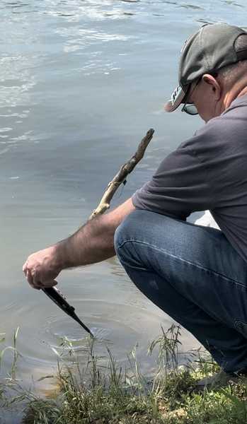
This is when I measured the temperature of Mammoth Spring after the dam. It was 58 degrees Fahrenheit.
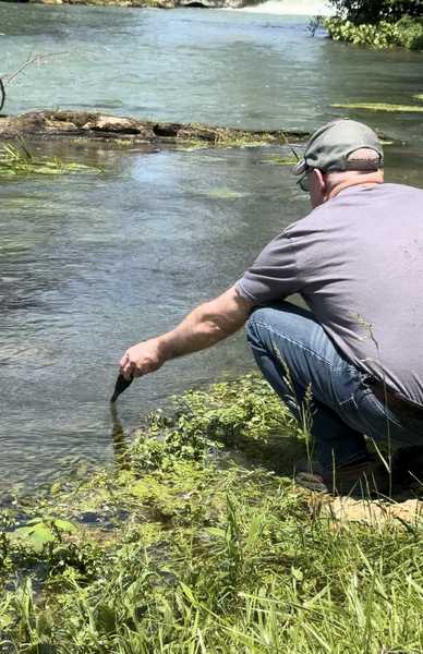
This is when I measured the temperature of Mammoth Spring right at the place where it comes out of the ground. It was 58 degrees Fahrenheit.
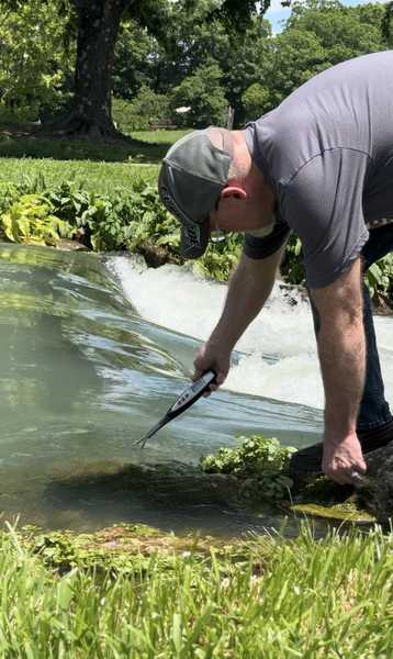
This is when I measured the temperature of Spring River about 1,800 feet down the river. It was 66 degrees Fahrenheit.
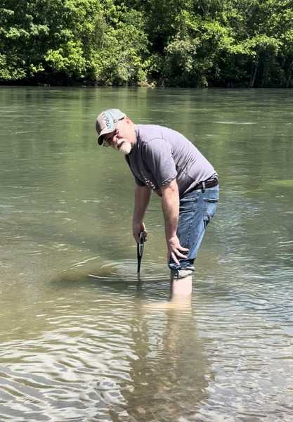
It was important to know the temperatures in advance so I could adjust the setpoint for the test of the Thermosphere. This is a birds eye view.
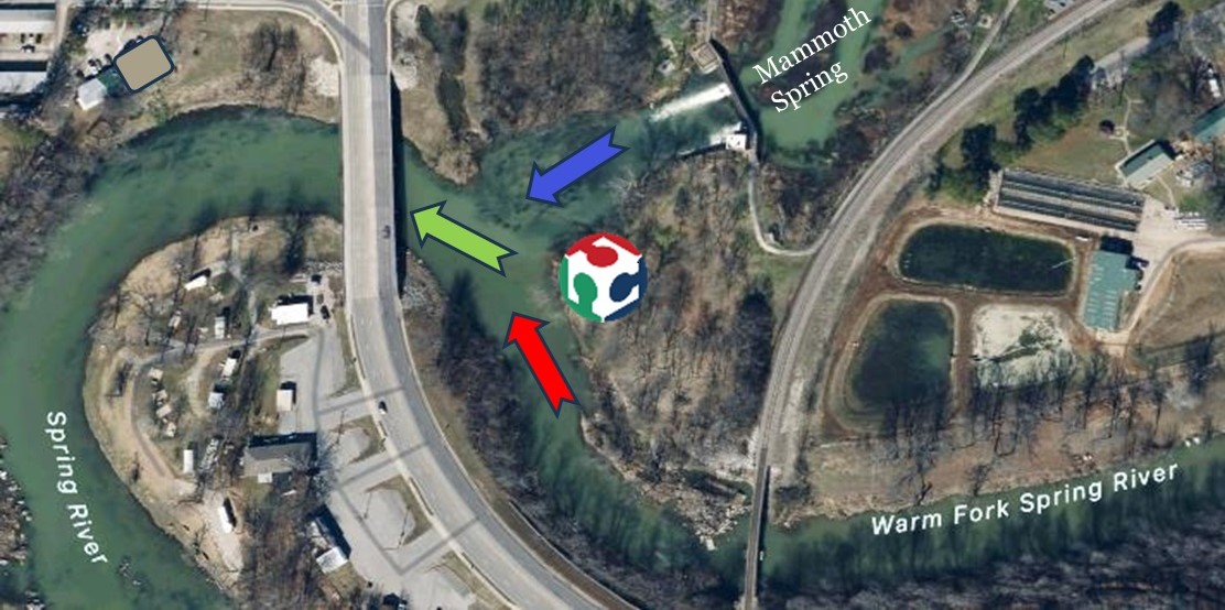
I programmed the setpoints and went back to the same location on Monday. This video shows the concept of what I have been describing.
W17 Pre-Produce Audiovisuals & Video Editing
-
Creating a script of what you want to show will actually help.
-
Parts: Final result, making-of, context and user. Storytelling is always the best way to inspire others.
Deliverables:
- Creating a script of what you want to show will actually help.
Continuing with what has been accomplished, I made a script with post-its on the whiteboard (a process I am only beginning to use :)

I started with the column labels and then began to flesh it out.
- Parts: Final result, making-of, context and user. Storytelling is always the best way to inspire others.
After telling my family about my test results and sending an image, my brothers asked, “What is it, a giant bobber?” Then my brother said, “Trout like the temperature to be below 70 degrees Fahrenheit.” That statement set the stage for the whole story. Use the ThermoSphere to Test The Waters so the user will know if the water temperature is good for trout fishing.
This is a revised script after taking these ideas into account.
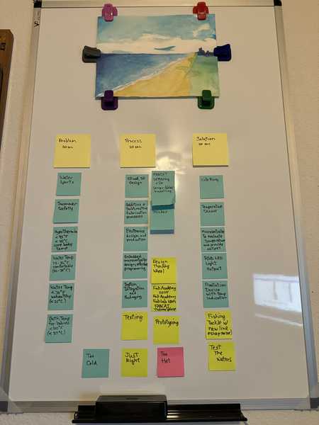
This enabled me to assemble the content into a flowing story from “Stating the Problem”, to “Showing the Process”, and then “Showing the Solution”. “Why”, to “HOW”, and then “Who, When, Where, and What”.
W18 Poster Production
-
Create a poster that summarizes the overall parts of your project.
-
Infographic style.
Deliverables:
- Create a poster that summarizes the overall parts of your project.
I went through several iterations to get the final results. The script really helped focus my thoughts as well as the help from my Instructors. I started with this.
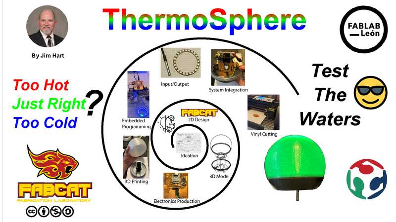
Removed the spiral and made the images bigger.
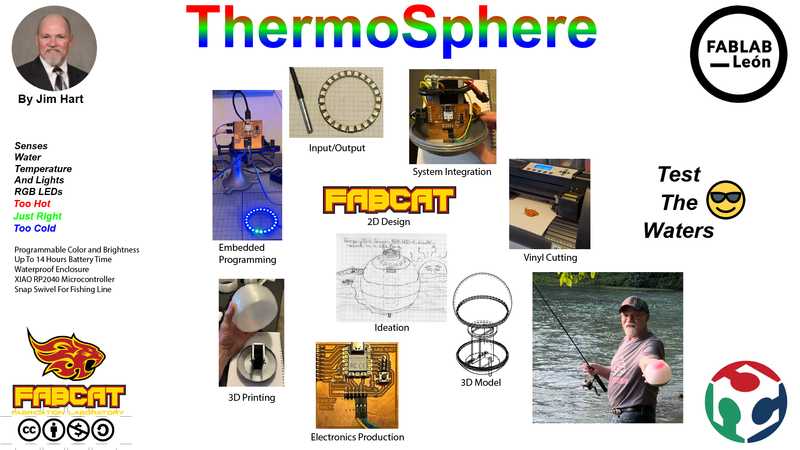
Then one more tweak to make the ThermoSphere more prominent.
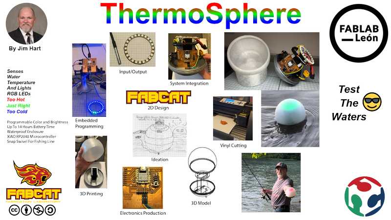
- Infographic style.
I had a great session during Global Open Time. The gathering of Instructors was so awesome. What an incredible opportunity. I showed them the Slide you just saw and they gave me some great tips. Henk Buursen guided me to make it more of an Infographic Style! Miriam Choi recommended moving the tag line to the top. Rico Kanthatham recommended putting the larger ThermoSphere in the center and place smaller images around the outside as well as change the size of my name. So many great ideas! This is what we arrived at.
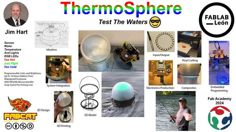
Linked to your presentation.png and presentation.mp4; make sure they are located to the root of your website
- Linked to your presentation.png and presentation.mp4; make sure they are located to the root of your website:
I am scheduled to present my Final Project to Professor Neil on Wednesday at the end of the session. You are welcome to join with us or view the video if you can’t be there. The links to my Personal Website, Presentation Slide, and the Presentation Video are on the schedule for Wednesday, 05 Jun 2024. The actual time may vary based on attendance.
Included the license you chose
- Included the license you chose:
The ThermoSphere Final Project may interest hobbyists and anglers to assist them with fishing. This project was funded as a personal expense for learning and fun. As my website shows in the footer, I am using the Creative Commons Attribution-NonCommercial-ShareAlike 4.0 International License.
Included all of your original design files in the archive (2D & 3D, board files & code). No external hosting of final project files - discuss file sizes with your instructor
- Included all of your original design files in the archive (2D & 3D, board files & code). No external hosting of final project files - discuss file sizes with your instructor:
Computer-Aided Design
-
Lettering of FABCAT Fab Lab V2 fabcat_lettering_v2.psd 305 Kb
-
3D Design Files 3d_design.zip 122 Kb
Computer-Controlled Cutting
- Cut Files computer_cutting.zip 11 Kb
Electronics Design and Production
- Board Files electronics.zip 291 Kb
3D Printing
-
Electronics Housing electronics_housing.zip 4.8 Mb
-
Inner Form inner_form.zip 2.6 Mb
-
Outer Form outer_form.zip 1.5 Mb
-
Support Ring support_ring.zip 1 Mb
-
Sensor Globe sensor_globe.zip 9.3 Mb
Embedded Programming
- MicroPython Code programming.zip 2 Kb