Electronics Production
This week I learned about the process of milling, stuffing, de-bugging and programming a development board. This included:
Unit Description
Group assignment:
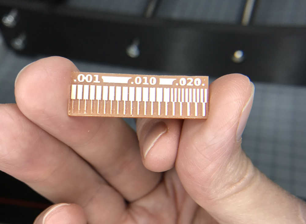
- Characterize the design rules for your in-house PCB production process: document feeds, speeds, plunge rate, depth of cut (traces and outline) and tooling.
- Document your work to the group work page and reflect on your individual page what you learned
Individual assignments:
- Make and test the development board that you designed to interact and communicate with an embedded microcontroller
Learning outcomes
- Described the process of tool-path generation, milling, stuffing, de-bugging and programming
- Demonstrate correct workflows and identify areas for improvement if required
Checklist
Linked to the group assignment page:
- Linked to the group assignment page:
This is a link to the LCCC Fab Academy 2020 Group Assignment. Since I was a remote student, I characterized the design rules for my PCB production process at the GOCAT Fab Lab. The process was similar and I list the results below:
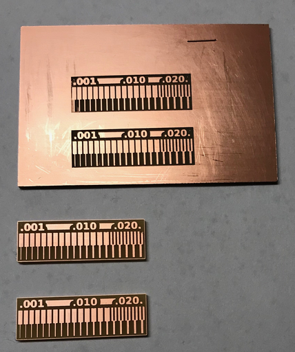
- Success: I made 2 test traces and cleaned them. I made multiple boards, but the last one was a keeper.
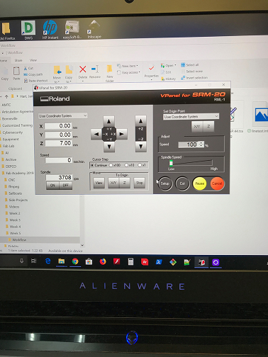
Vpanel spindle speed setting:
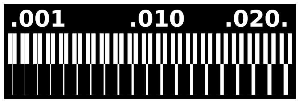
The linetest interior (outer cut):

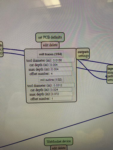
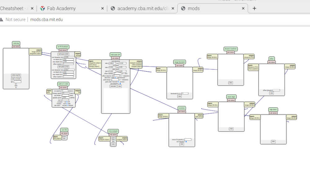
The Mods setup:
RML file outputs:
linetest interior (outer cut).
This is a continuation of the Electronics Production week in Fab Academy 2022
Documented how you made the toolpath:
-
Documented how you made the toolpath:
-
Success: I learned how to mill with a new machine (CNC3-3018Pro) in my basement. I attempted 2 boards. The first board with the linetest looked good, but the depth setting was not sufficient to mill the whole board.
-
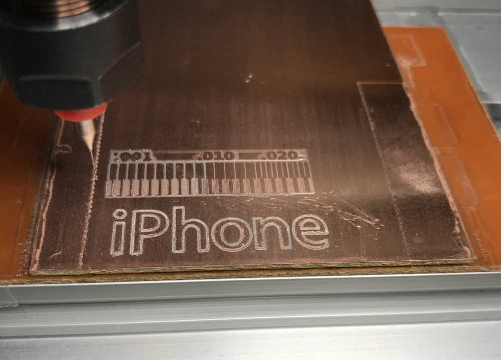
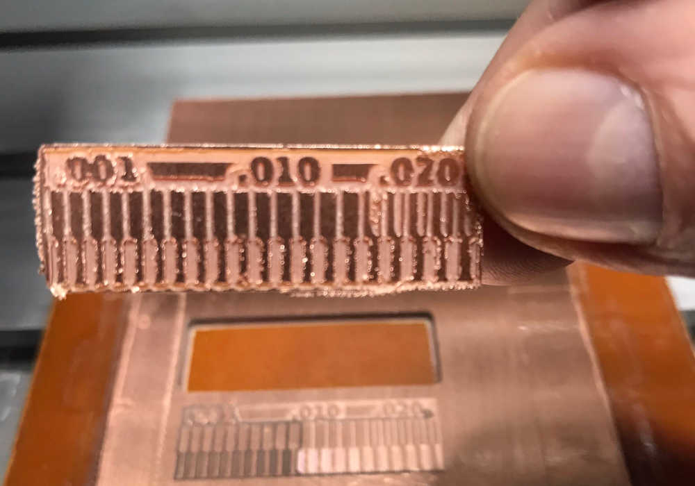
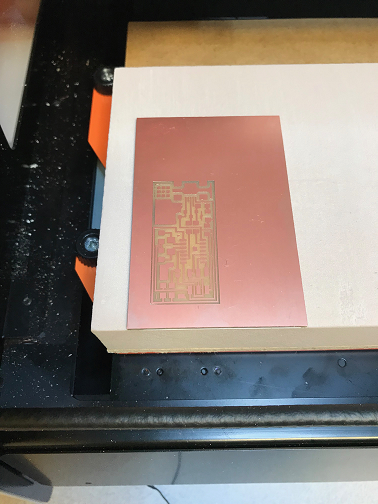
Milled iPhone in FR-1 board to test CNC3-3018Pro (named Sweety)
-
Used mods to make the g-code for the linetest.png and linetest.interior.png images from Neil to —Characterize the design rules for your PCB production process: document feeds, speeds, plunge rate, depth of cut (traces and outline) and tooling.
-
Obtained the images from electronics production, under CAM and stored them in the files directory for this week; to be used in future processes.
-
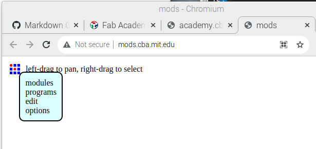
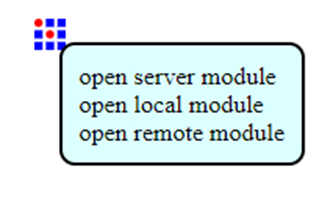
Right-click on CBA logo.
-
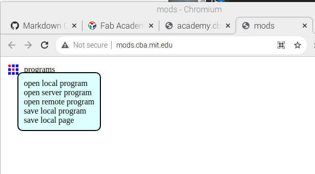
Click on programs.
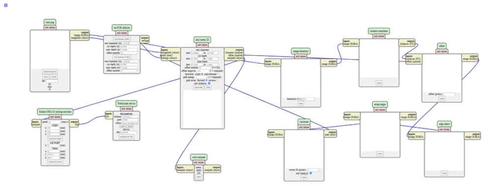
- Click on open server program.
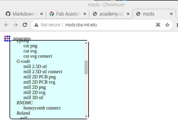
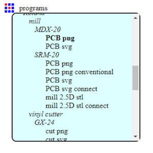
- Scroll down to G-code
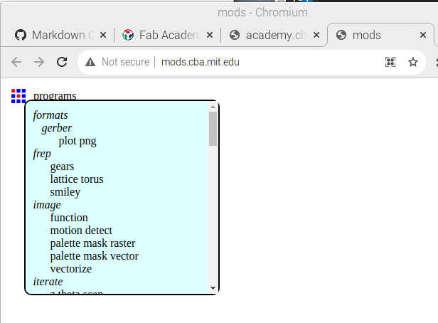
- Click mill 2D PCB png
- A wonderful solution opens in your page.
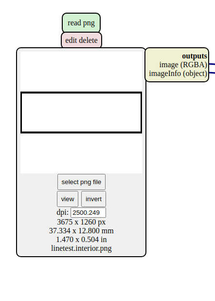
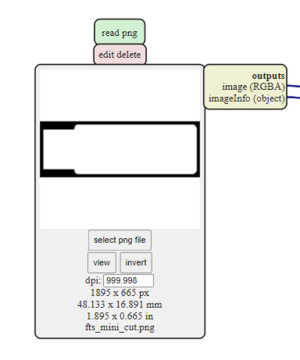
- Click select png file in the first module and find your linetest.png file.
- It will be displayed in the module.
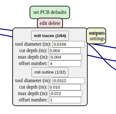
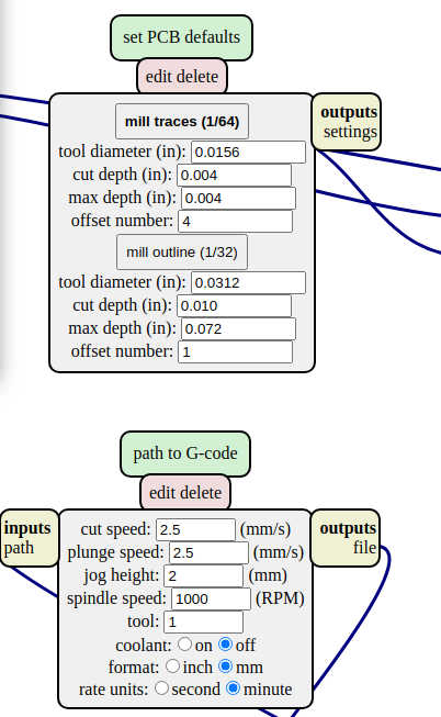
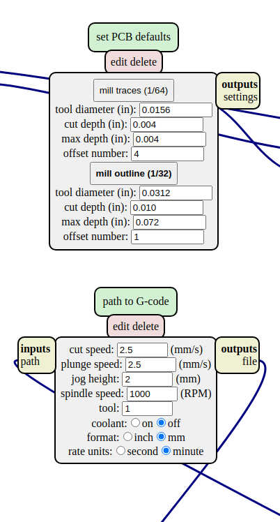
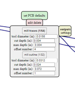
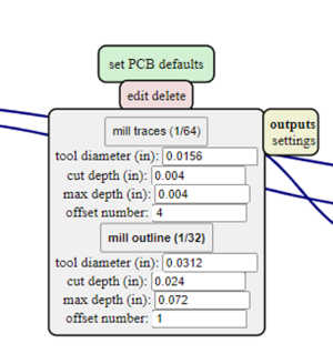
- Click mill traces (1/64) in the set PCB defaults module. Accept all defaults as appropriate.
- I need to set the spindle speed to 1000 (in path to G-code module below), since the CNC3-3018Pro expects this for maximum speed of 10,000 RPM.
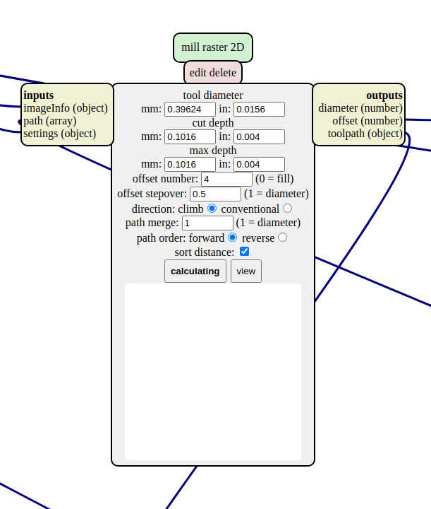
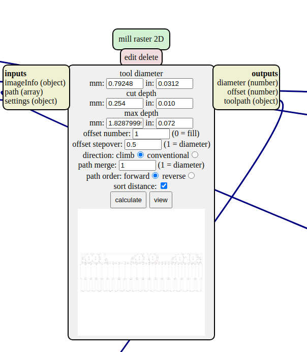
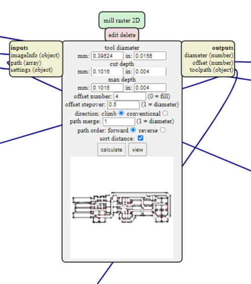
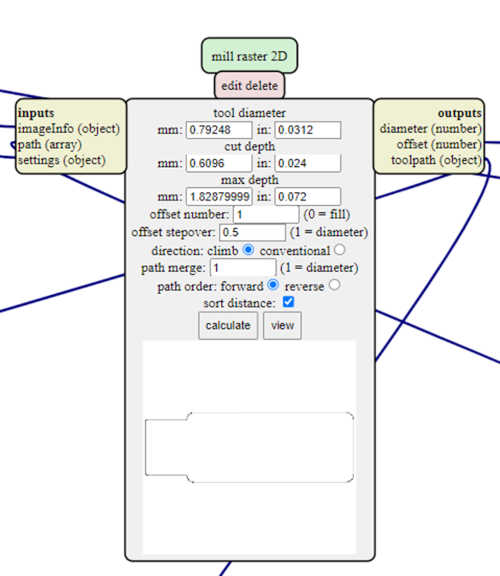
- Click calculate in the mill raster 2D module.
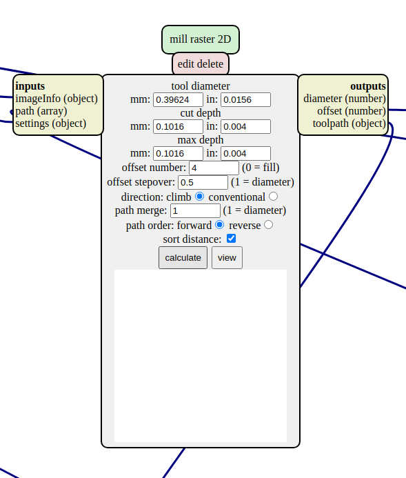
- You will see the calculate button turn to calculating…Wait for it! Wait for it! You will see the raster image to begin to show in the same module.
-
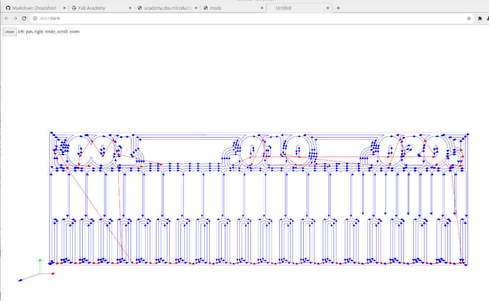
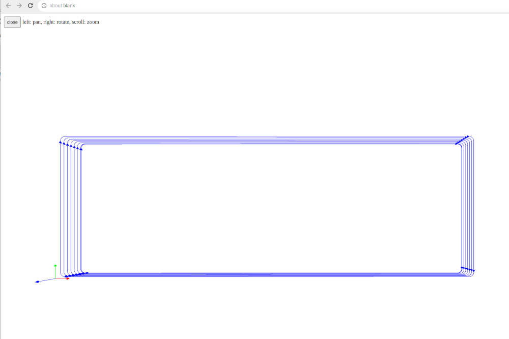
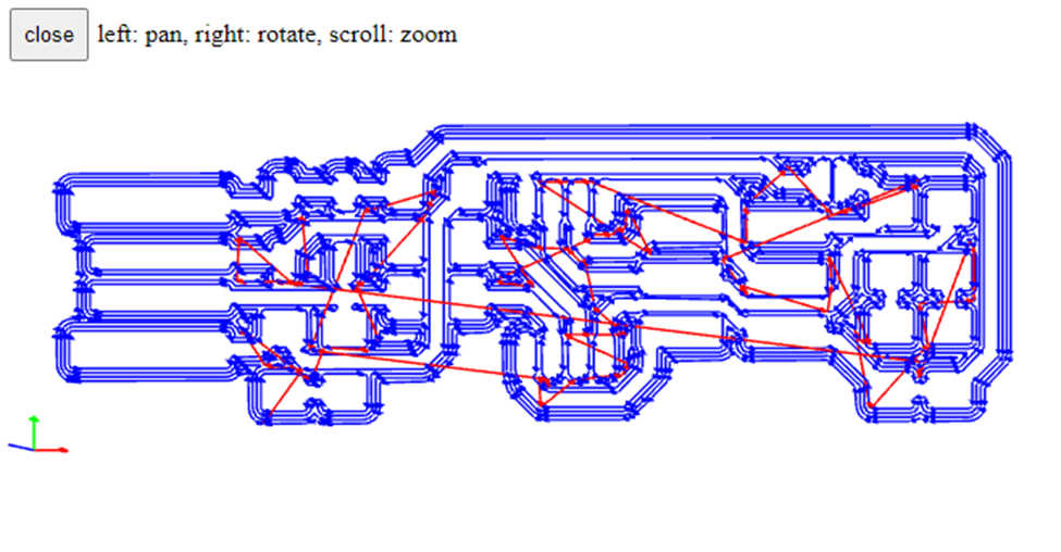
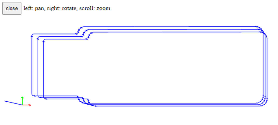
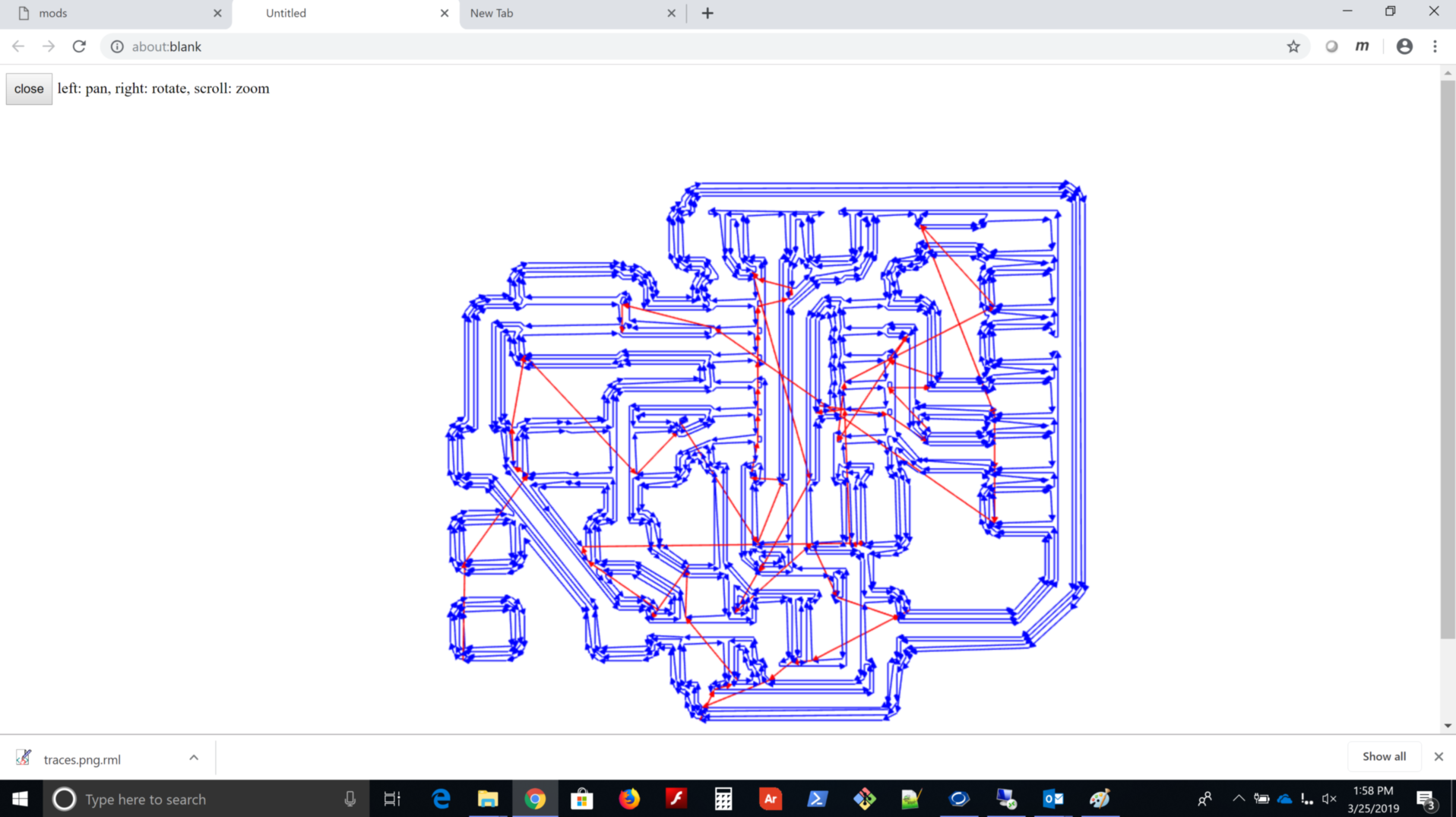
Once finished, you will receive the .nc file as a download and you will see a beautiful image of the toolpath; you can use your mouse to see the whole image (left: pan, right: rotate, scroll: zoom) cool!
-
Once you have your file and enjoy the toolpath graphic, you are ready to make your outline .nc file. Click close in the upper left corner.
- In similar steps, Click select png file in the first module and find your linetest.interior.png file. It will be displayed in the module.
- Click mill traces (1/32) in the set PCB defaults module. Accept all defaults as appropriate. I need to set the spindle speed to 1000 (in path to G-code module below), since the CNC3-3018Pro expects this for maximum speed of 10,000 RPM.
- Click calculate in the mill raster 2D module.
- You will see the calculate button turn to calculating…Wait for it! Wait for it! You will see the raster image to begin to show in the same module. Once finished, you will receive the .nc file as a download and you will see a beautiful image of the toolpath; you can use your mouse to see the whole image (left: pan, right: rotate, scroll: zoom) again, very cool!
- Once you have your file and enjoy the toolpath graphic, you are ready to mill your board. Click close in the upper left corner.
Documentation of traces and outline:
-
feeds - 2.5 mm/s
-
speeds - 10,000 rpm
-
plunge rate - 2.5 mm/s
-
depth of cut - 0.004 in
-
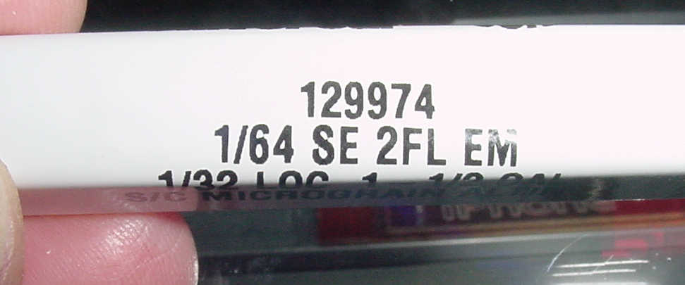
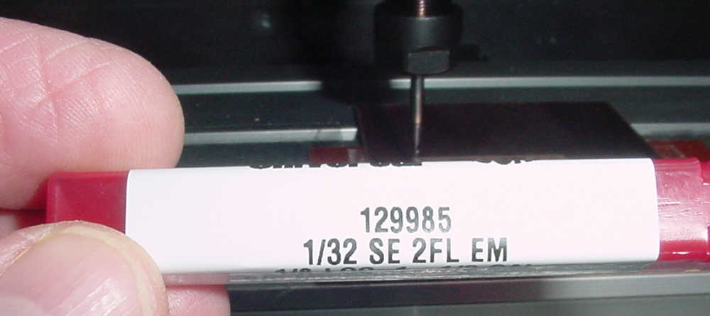
tooling - Carbide Depot endmills: traces 1/64in SE 2FL, outline 1/32in SE 2FL
-
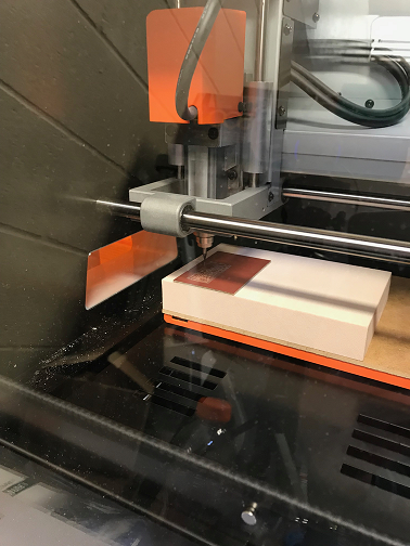
Rico recommended a containment for Sweety using an inverted transparent plastic tote. What a great idea! Thanks Rico!
-
Used Candle, provided by vendor, to load the g-code; there were errors, the spindle started, but did not move/mill. I searched FA for 3018 and found several entries. There were helpful hints to modify the g-code to make it work on Sweety.
-
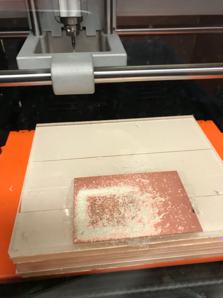
Milled the first line test. The left half milled nicely, but the right half did not plunge sufficiently. I zeroed the Z on the left side where the board had lifted up; the right side stayed fixed, so it was lower; this caused the limit plunge depth.
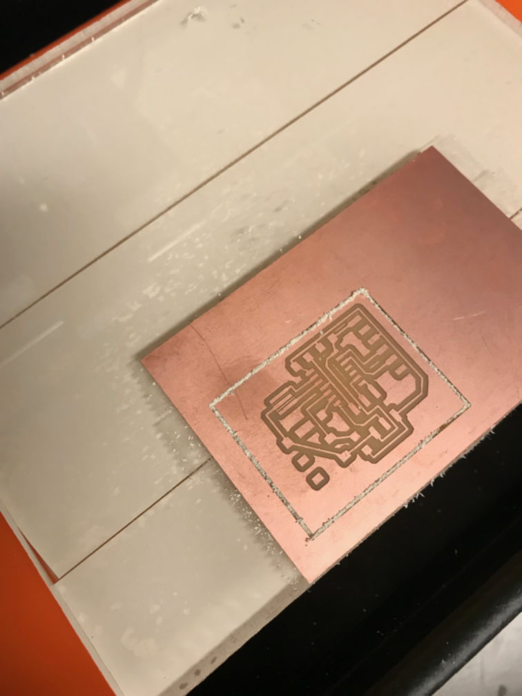
- I zeroed Z 0.1mm closer and the second board was milled completely. However, the endmill was longer and weaker than the carbide depot brand; this resulted in poor milling of the second board. I was able to mill the outline and separate the board. I was excited to see the results.
-
When generating the g-code through mods, I used the same recommended changes to the code and discovered a problem. The units were set to inches and the board was huge on the screen. I realized the problem when I did a dry run (cutting air) and the mill went beyond the board; the feed rate was extremely slow too. I edited the g-code to fix the problems. Turns out, I only need to modify one line after mods generates the g-code. It was line 15 “G04 P1000” changed to “G04 P1” (shorter wait :) I am looking forward to trying again.
-
In my excitement to get another board made, I failed to change the endmill from 1/32” to 1/64”. The machine did just as it was told without regard to the size of the endmill. Lessons learned: make the hardware match the software; better yet, always remove the endmill after the job! Additionally, don’t use tape over the area to be milled; it can be cleaned, but post-processing is lengthened considerably.
- I need to finish this group assignment before I change Sweety’s end effector to a laser. (With proper laser safety observed :)
Research
- Went through all of the electronic parts inventory to review what was available.
Explained any problems and how you fixed them:
- Explained any problems and how you fixed them:
Results
-
Description: Complete assignments and produce outcomes of Week 5 Electronics Production.
-
Requirements: Show how I made and programmed the board; explained any problems and how I fixed them; include a ‘hero shot’ of my board
-
Planning: Setup the Roland SRM-20 mill for board production.
-
Materials: Using current laptop, internet connection, and Roland SRM-20 mill. Used MDF and synthetic wood to make a sacrificial platform. Fume extractor. Solder station and supplies. Microcontroller: 1x ATTiny 44 microcontroller; Discrete devices: 1x Crystal 20MHz; 2x Resistor 100 ohm; 1x 499Ω resistors; 1x Resistor 1K ohm; 1x Resistor 10K; 2x 3.3v zener diodes; 1x red LED; 1x green LED; 1x Capacitor 1uF; 2x Capacitor 10 pF 1x 2x3 pin header; 1x USB connector; one usb mini cable
-
Problems: I made 2 test boards successfully, but crashed 2 endmills in the learning process; my feed rate was set at 4 mm/sec. After several runs, the sacrificial board was getting worn and caused multiple bad parts.
-
Corrections: Slowed the feed rate to 3 mm/sec and never crashed another endmill. I moved the FR1 to the other side of the sacrificial board and the parts worked great.
- Workflow: I used the mods after watching the tutorial videos and reading the 5.1 MODS tutorial. At first it was confusing, but practice makes perfect. Mods makes it so easy. Thank you, Neil!
-
Learning: I have used a large mill, but had a lot of help. This was the first time I made parts completely solo; it was a great learning experience.
-
Using Roland SRM-20 mill is so much easier now. I look forward to making more boards.
-
Fabbed 2 USBTiny boards using Bryan’s page
This is a remix of tutorial 5.1 MODS by Eduardo Chamorro. I adapted it to the workflow I would be using.
Step 1 obtain the files: Find or Design a Circuit Board
- I will be using the traces file from the FabTinyISP as well as the outline cutout
Step 2: MODS - Setup (1/64)
Mods for PCBs
- Go to http://mods.cba.mit.edu/
- right click/two finger/long press for menu; scroll for zoom, drag for pan
- right click the CBA logo
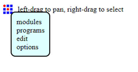
- Click on programs
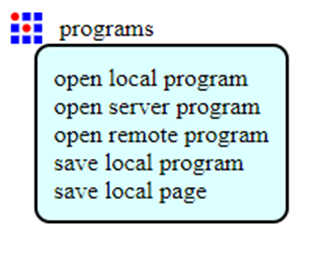
- Click on open server program
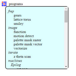
- Scroll down to SRM-20 and Click PCB png
- Since I will be saving this to a file, I will need to add a save file module
- right click the CBA logo
- Click modules
- Click open server module
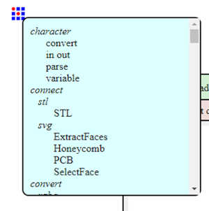
- Scroll down to file and click save
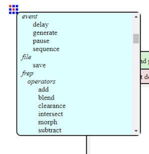
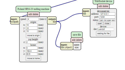
- Click and drag the green “save file” button to move the save file module and move it down between the Roland SRM-20 milling machine module and the WebSocket device module
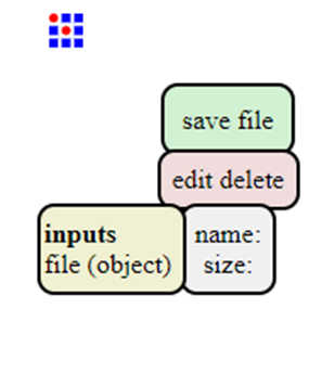
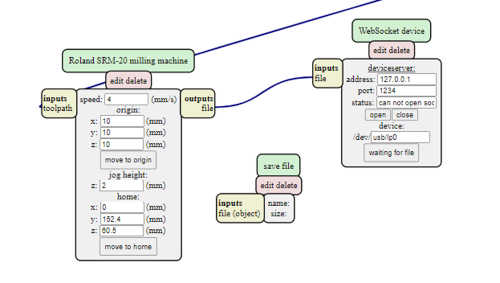
- Click on the unbolded “file (object)” word in the inputs button of the save file module, and then the unbolded “file” word of the outputs button on the Roland SRM-20 milling machine module; this will connect the two modules and provide an output file on your local machine.
Step 3: MODS - Traces (1/64)
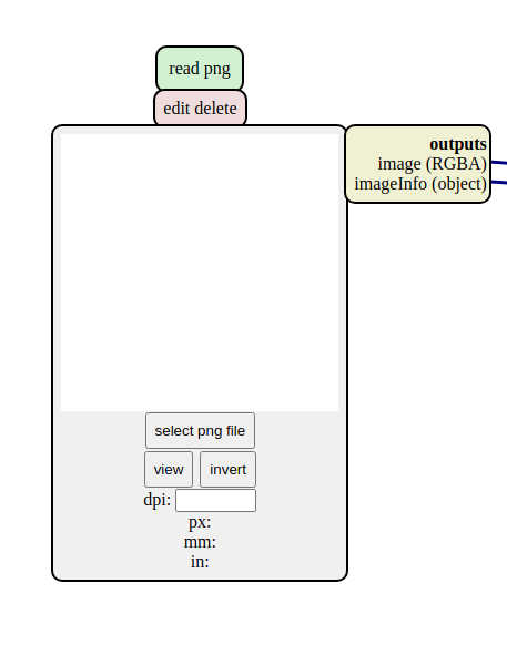
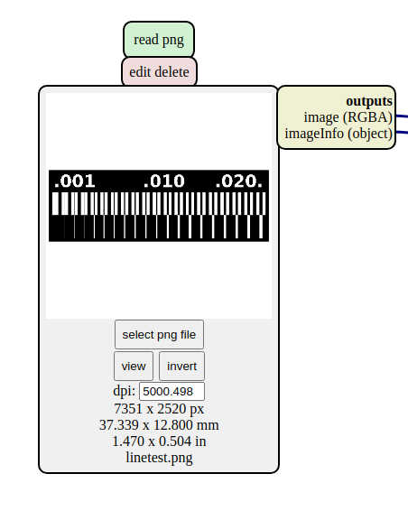
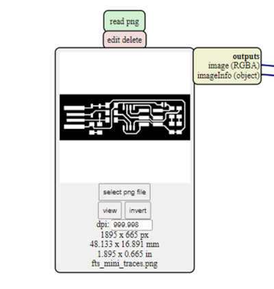
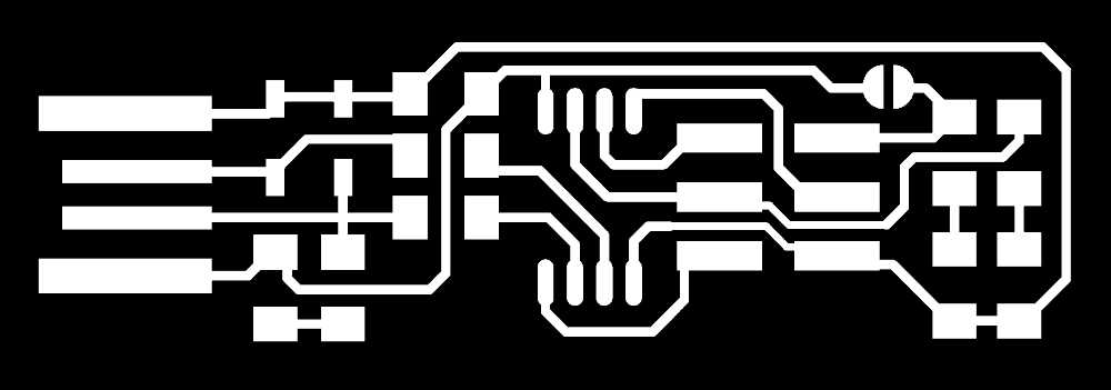
Open your traces image file (This is the one with lines that will form the wires between your components.)
- Go to READ PNG MODULE SELECT- PNG FILE - select your traces image
- In SET PCB Default module click in MILL TRACES 1/64
- In Mill Raster 2D module click in Calculate
- The file will be saved automatically into your download folder.
- The toolpath will be displayed on the screen. You can manipulate it to view it and then click Close
VALUES THAT YOU CAN MODIFY – You should make the appropriate changes before you click Calculate
-
In module Roland SRM-20 milling machine Origin
- x0(mm) - 0
- y0(mm) - 0
- z0(mm) - 0 These x0,y0,z0 are for setting up an offset from the origin save in
- zjog - 12
- This is the z distance that the mill will go up between the air travellings
- Speed - 4 or 3 mm/s for new end mills
-
x/y/x home is the parking position after finishing the cut
Step 4: MODS - Outcut/Holes (1/32)
Open your outcut/holes image file (This is the one with lines that will be cut around your board as well as the holes.)
- Go to READ PNG MODULE SELECT- PNG FILE - select your outcut/holes image

- In SET PCB Default module click in MILL TRACES 1/32
- In Mill Raster 2D module click in Calculate
- The file will be saved automatically into your download folder.
- The toolpath will be displayed on the screen. You can manipulate it to view it and then click Close
VALUES THAT YOU CAN MODIFY – You should make the appropriate changes before you click Calculate
-
In module Roland SRM-20 milling machine Origin
- x0(mm) - 0
- y0(mm) - 0
- z0(mm) - 0
- zjog - 12
- Speed - 0.5
-
Click “calculate”(you will see the path calculating), when the process will finish it will “automatically be saved into your downloads folder”
Step 5: SEND THE FILES TO A ROLAND CNC
You will need to warm up the spindle using the maintenance procedure in Roland VPanel for SRM-20; be sure to set the spindle speed to low before running the maintenance.
Use double-sided tape to fix the board to the table.
Install a 1/64” endmill and zero the x, y, and z positions. Cut the traces. Install the 1/32” endmill and zero the z position. Cut the board edge and holes.
Step 6: Stuff the FabTinyISP
Step 7: FabISP: Programming
- Programmed first board without any problems
- Programmed the second board after debugging by reflowing solder
Documented how you made (milled, stuffed, soldered) the board:
-
Documented how you made (milled, stuffed, soldered) the board:
-
Used pcb.py and frep.py to “Design It” and generate these images to bring into mods
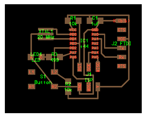
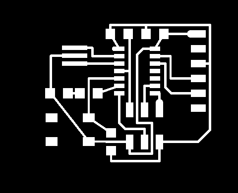
- “Make It”
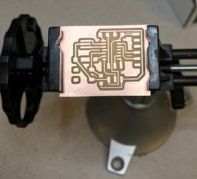
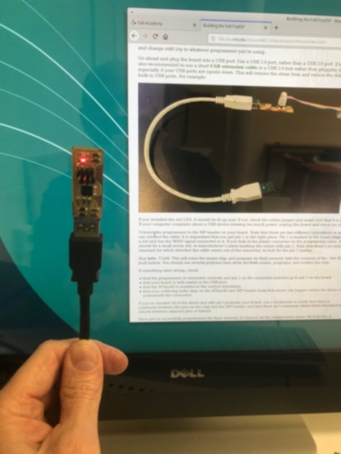
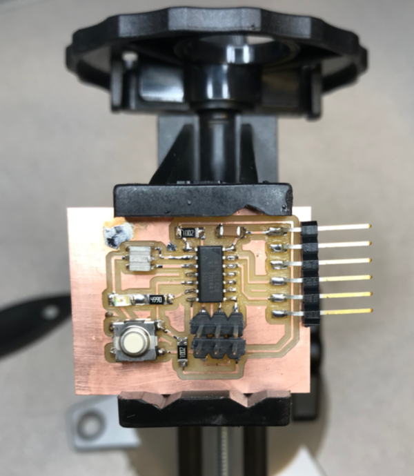
Included a ‘hero shot’ of your board:
- Included a ‘hero shot’ of your board:
- “Program It”
Make the hex code to be flashed; I used Neil’s hello.ftdi.44.echo.interrupt.c.make and hello.ftdi.44.echo.interrupt.c
jimhart@jimhart-Xubuntu2:~/avr$ make -f hello.ftdi.44.echo.interrupt.c.make
avr-gcc -mmcu=attiny44 -Wall -Os -DF_CPU=20000000 -I./ -o hello.ftdi.44.echo.interrupt.out hello.ftdi.44.echo.interrupt.c
avr-objcopy -O ihex hello.ftdi.44.echo.interrupt.out hello.ftdi.44.echo.interrupt.c.hex;\
avr-size --mcu=attiny44 --format=avr hello.ftdi.44.echo.interrupt.out
AVR Memory Usage
----------------
Device: attiny44

Program:     830 bytes (20.3% Full)
(.text + .data + .bootloader)

Data:         74 bytes (28.9% Full)
(.data + .bss + .noinit)
Flash to board through ftdi using avrdude
jimhart@jimhart-Xubuntu2:~/avr$ avrdude -c usbtiny -p attiny44 -U flash:w:hello.ftdi.44.echo.interrupt.c.hex

avrdude: AVR device initialized and ready to accept instructions

Reading | ################################################## | 100% 0.00s

avrdude: Device signature = 0x1e9207 (probably t44)
avrdude: NOTE: "flash" memory has been specified, an erase cycle will be performed
         To disable this feature, specify the -D option.
avrdude: erasing chip
avrdude: reading input file "hello.ftdi.44.echo.interrupt.c.hex"
avrdude: input file hello.ftdi.44.echo.interrupt.c.hex auto detected as Intel Hex
avrdude: writing flash (830 bytes):

Writing | ################################################## | 100% 1.27s

avrdude: 830 bytes of flash written
avrdude: verifying flash memory against hello.ftdi.44.echo.interrupt.c.hex:
avrdude: load data flash data from input file hello.ftdi.44.echo.interrupt.c.hex:
avrdude: input file hello.ftdi.44.echo.interrupt.c.hex auto detected as Intel Hex
avrdude: input file hello.ftdi.44.echo.interrupt.c.hex contains 830 bytes
avrdude: reading on-chip flash data:

Reading | ################################################## | 100% 1.66s

avrdude: verifying ...
avrdude: 830 bytes of flash verified

avrdude: safemode: Fuses OK (E:FF, H:DF, L:5E)

avrdude done.  Thank you.
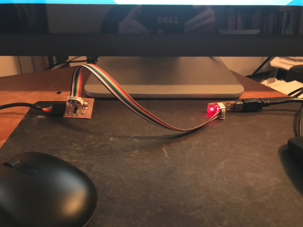
Documented that your board is functional:
-
Documented that your board is functional:
-
“Test It”
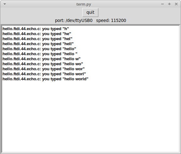
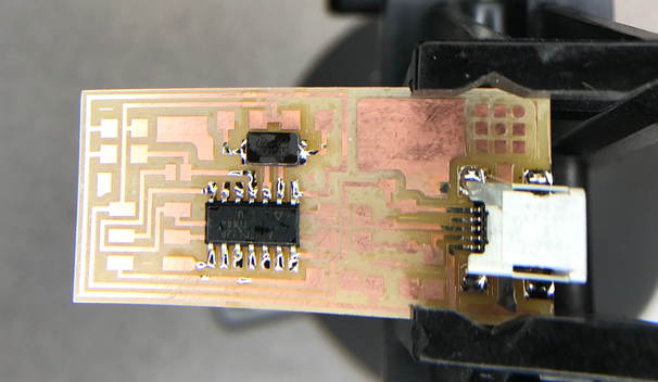
I used Neil’s board as a guide and stuffed the python board from scratch; that, running the traces, and milling the board took the rest of my Saturday. That night, I made Hello World work. On Sunday, I got the LED to flash S-O-S when I held the button.
Make the hex code to be flashed; in this case it is called kellyBlinkCode.c and kellyBlinkCode.make. I flashed the program to the board using my usbtiny. Here is the result:
-
Here are some artifacts of where I have been. Kelly Shaw really helped me out today! Thanks, Kelly!! http://fab.cba.mit.edu/classes/863.11/people/kelly.shaw/week7_embedded_programming.html
-
Referred me to this http://highlowtech.org/?p=1695 and this http://highlowtech.org/wiki/pmwiki.php?n=Main.AVRProgrammingAdvanced But this was the biggest find of all from Kelly http://www.nongnu.org/avr-libc/ and this http://www.nongnu.org/avr-libc/user-manual/pages.html and got me to this https://www.microchip.com/webdoc/AVRLibcReferenceManual/group__avr__io.html
This is a continuation of the Electronics Production week in Fab Academy 2024
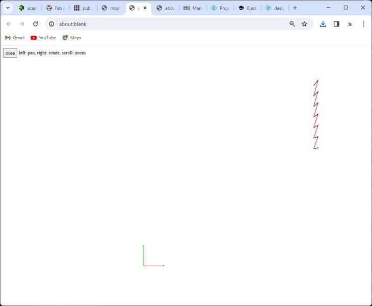
- I thought I should brush up on my soldering skills so I completed this practice board provided by the vendor.
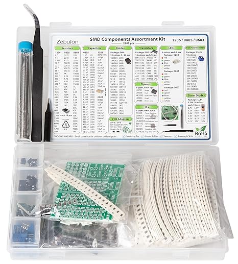
- This is the result. I was able to solder the chip on but I tried to remove it for practice and to reduce the solder I used, but I ended up ripping the solder pads off of the lower edge.
-
I feel more confident about my soldering skills, but I need to practice rework a lot more :)
-
Since the students of the Fab Academy 2024 cycle were making the QuenTorres XIAO RP2040 development board, I thought I would as well. This will be used for my spiral toward the Final Project.
-
My first step was to mill the board, so I had to take the png provided by Quentin and Adrian from this site. I chose version 2 so I could interchange the XIAO boards on the riser.
-
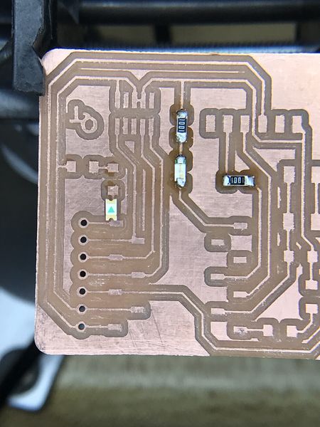
For the traces I used the 1/64” endmill with a cut and plunge speed of 1.5 mm/sec, jog height of 2 mm and a spindle speed of 1000 RPM (this is approximately 10000 RPM for a 775 spindle motor on the 3018)
-
For the interior and drills I used the 1/32” endmill with the same settings as the traces except that the max depth is 1.8 mm so that it goes through the board.
-
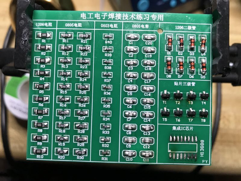
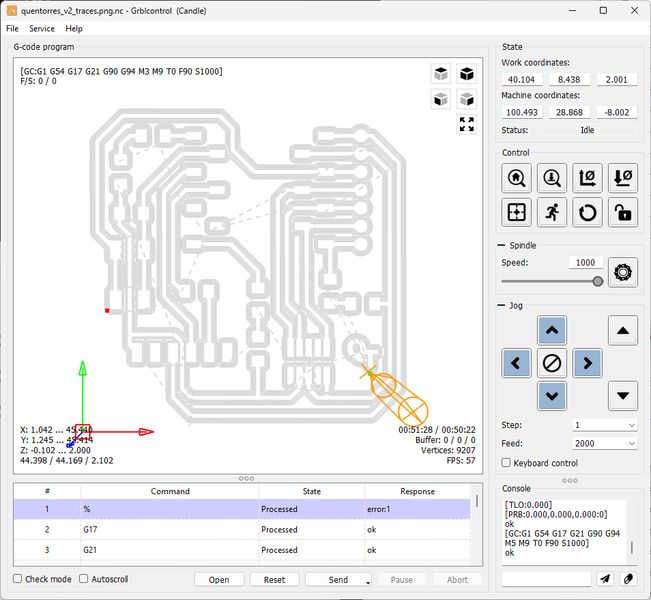
This is the tool path for the traces:
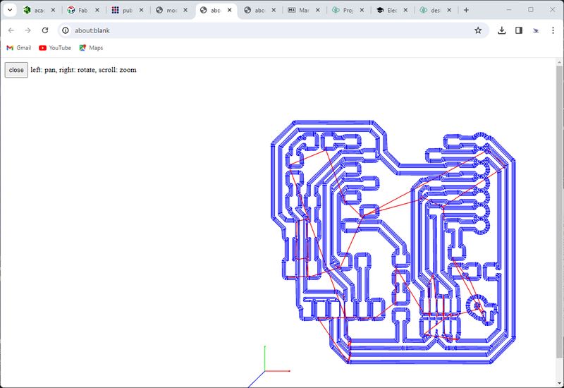
- This is the toolpath for the interior:
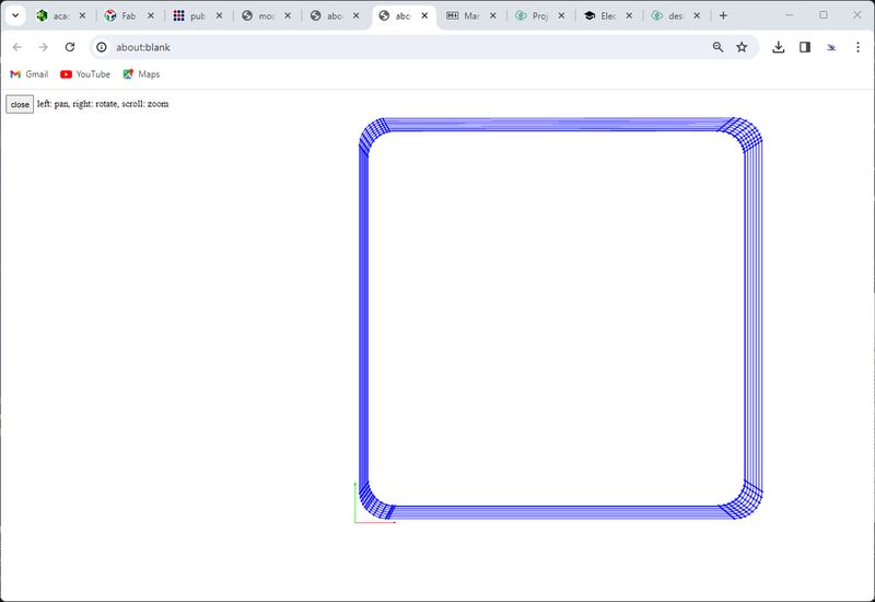
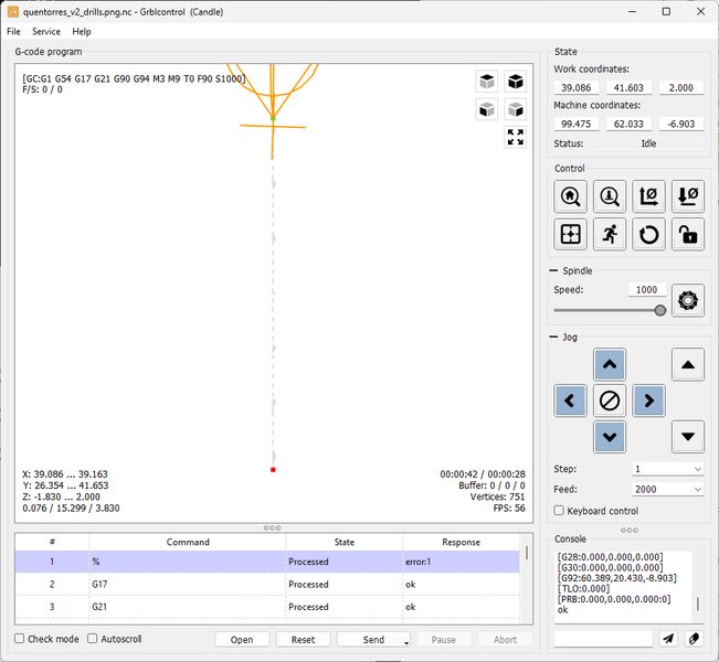
- This is the toolpath for the drills:
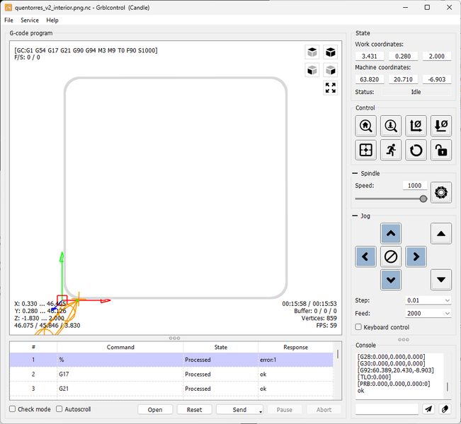
- I zeroed the XY and Z axis and sent the traces gcode to MySweety using Candle and remembered that I had to change the gcode before I sent the job. It was line 15 “G04 P1000” changed to “G04 P1” (shorter wait :). I get an error due to the % at the beginning of the file, but I click Ignore and it starts milling. During my first try, the endmill quit cutting after I went around the first corner. I thought I broke the endmill, but it was okay. Not sure what happened…maybe the nut on the collet wasn’t tight enough. I retightend it and it seems to be working just fine. Once I finish the traces I will sent the drills gcode to MySweety.

- I brought the spindle back to XY Zero and changed the endmill to 1/32”, zeroed the endmill and then brought it up to 7 mm and zeroed it so I could cut air and make sure it was going to be on target. I sent the drills job. All went well, so I zeroed the Z axis and sent the job again. So far so good :)
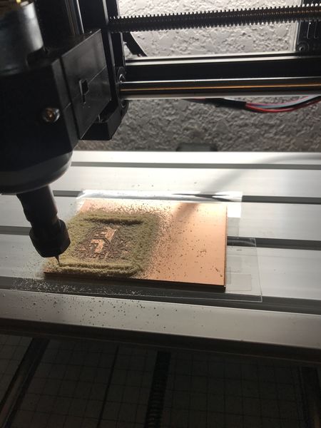
- Last file was the interior. I went to zero on XY, sent the job and all went well. Lots of chips/dust since I have to release this from the wasteboard.
- Here’s the result:
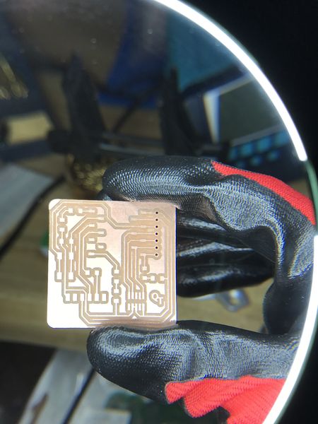
- Dust removed.
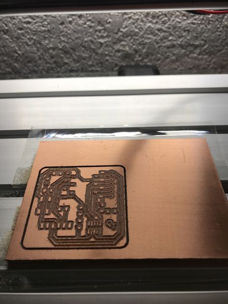
- Prying out the board
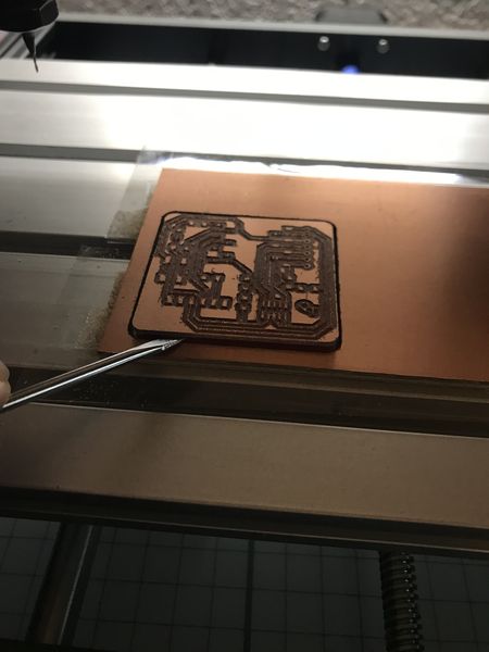
- QuenTorres is released!

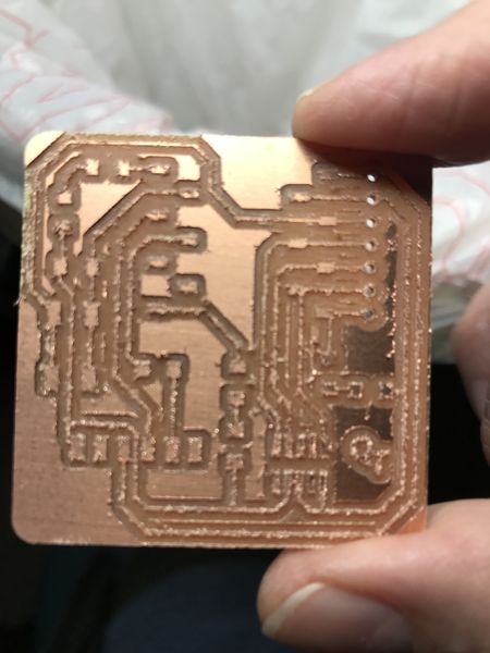
- First glance.
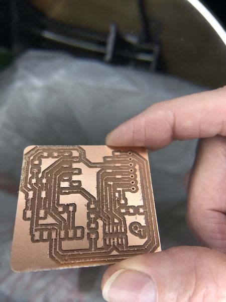
- First closeup.
- Ready for stuffing!
Stuffing Saturday
-
You see what I did above on Friday. It was a full and fun Fab Friday, but I did not finish the QuenTorres. After Global Open Time (GOT), I hurried back to the solder bench.
-
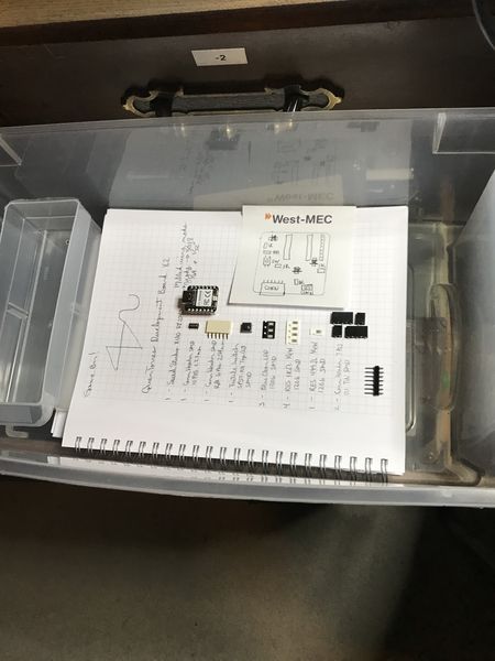
The first order of business was to organize/plan, so I sketched the BOM in my notebook that I used in GOT.
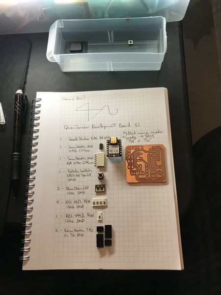
- Then I added a sketch on the post-it note to show the location of parts and added the pins I will be soldering into the drilled holes.
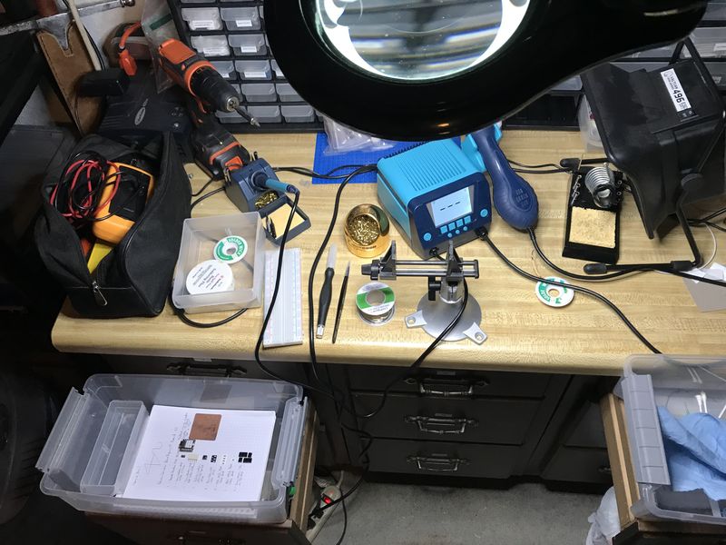
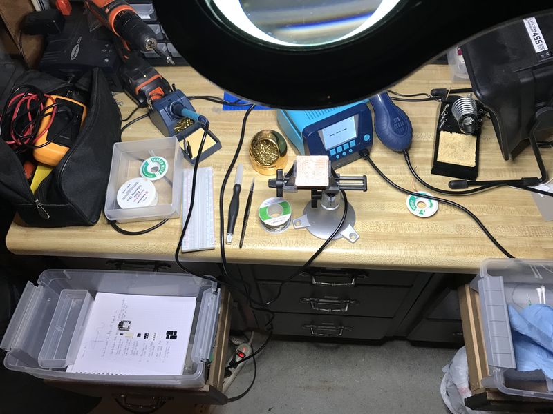
- So here is my soldering workbench.
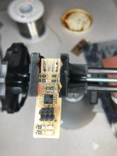
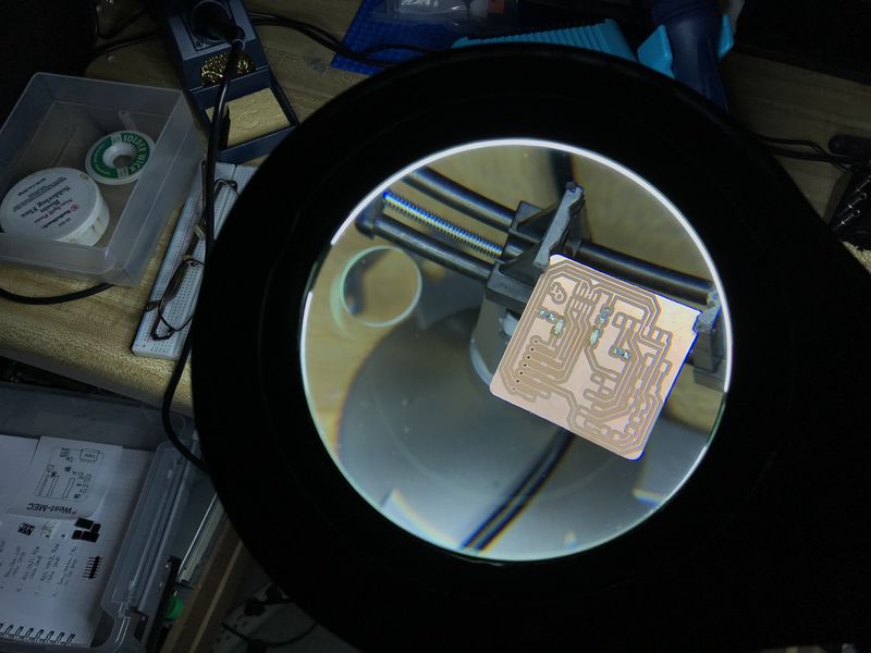
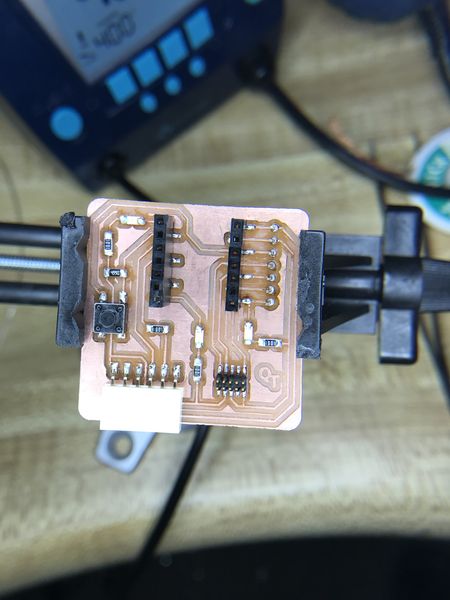
- This is the QuenTorres board in the vise ready for stuffing.
- I started soldering the LEDs and resistors first, but I thought I should verify the polarity of the LED. This is the bottom of the LED showing the proper direction on the board. The arrow points in the direction of conventional current flow; positive (+) to negative (-). Another tip is the shape of the triangle looks like an A and is pointing toward the anode (+).
- This is the top of the LED showing the proper direction on the board. The green end is the cathode (negative) end and points toward ground (negative) through the resistor in the direction of conventional current flow; positive (+) to negative (-).
-
I heard Rico Kanthatham mention that a LED polarity can be tested with a multimeter. In all my years of electricity and electronics, I have never tried that! I have tested diodes, but never a LED. Thank you Rico! This was an exciting moment to try. Sure enough, when you select the continuity/diode test that beeps for continuity, connect the black lead (-) to the cathode and the red lead (+) to the anode, the LED lights, but there is no beep. You’ve got to see this, but more important, you’ve got to try this!
-
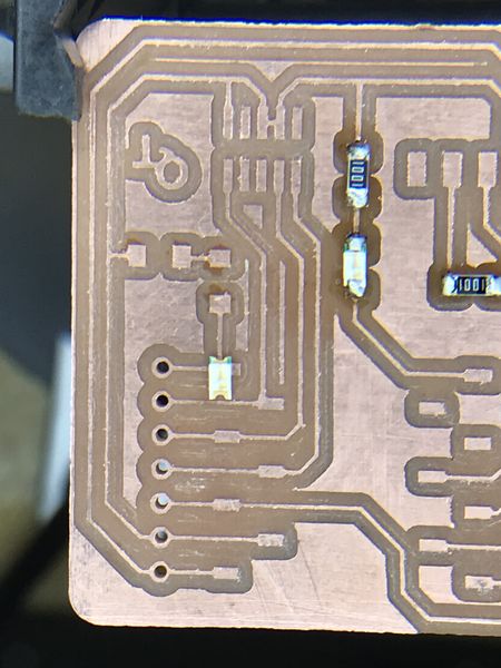
So here is the board stuffed with two LEDs and the 1K resistors.
- Here is the setup of the multimeter.
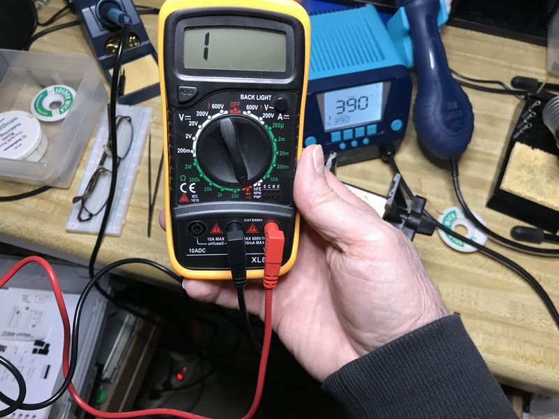
- Now for the show :)
- I tested all of the LEDs after I got to this point and tested the pushbutton too. So far so good!
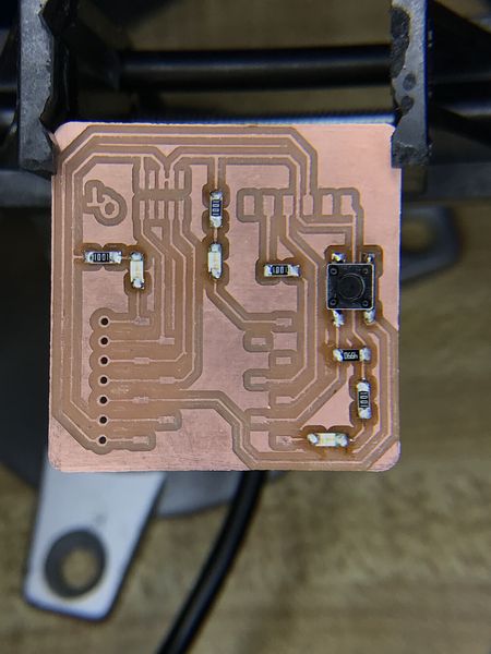
- Now I must stuff all of the connectors and pins. And finished by the end of the day!
Uploaded your source code:
- Uploaded your source code:
Source Code C, Make, RML