4. Electronics Production
Our group assignment was characterize the design rules for out PCB production process. We were challenged to determine feeds, speeds, plunge rate, depth of cut and tooling.
Useful links to our Student Sites
- Alecia Gorski Fab Academy Site
- Christopher Leon Fab Academy Site
- Hallie Krudy Fab Academy Site
- Ryan Corrigan Fab Academy Site
- Sydney Richardson Fab Academy Site
Learning Outcomes Displayed
- Defining the process of milling, stuffing, de-bugging and programming.
- Demonstration of correct work flows and identifying areas for improvement … if needed.
Research
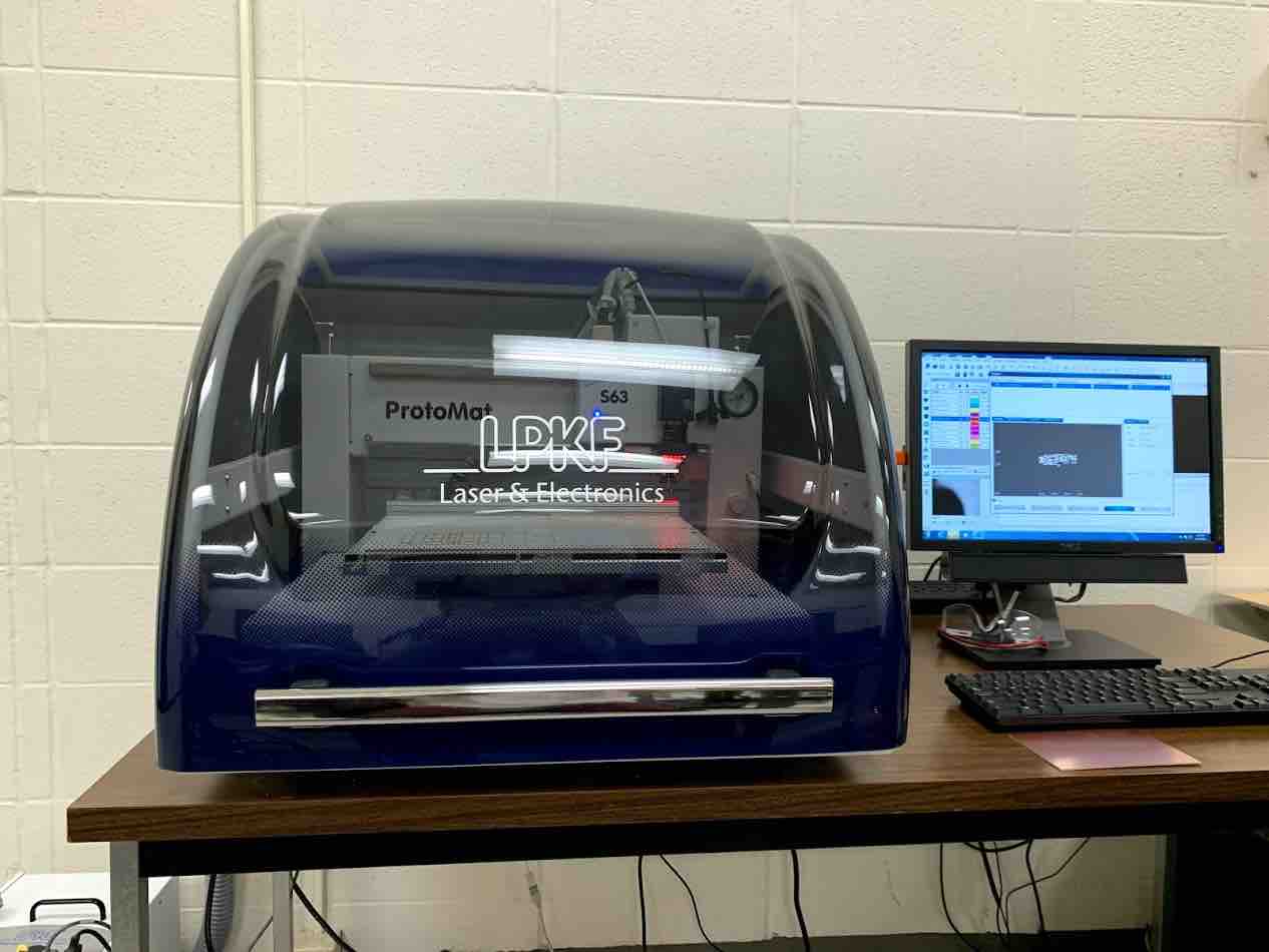
For this assignment we worked with the LPKF ProtoMat S63 Electronics Board Mill. This machine is an all-rounder for rapid PCB prototyping.
Milling Parameters and Design Rules
- Feeds - Our Milling Spindle was equal to 60,000 rpm and controlled by the software. The milling spindle speeds cut times down for each run and provides the highest accuracy.
- Speeds - Our Drilling speed is equal to 120 strokes/min.
- Material Thickness - .061 in
- Copper Thickness - 1.4 millimeters
- Cut Depth per pass - .1 millimeters
- Tooling - The Automatic tooling with 15 tool options allows for our jobs to be run independently and saves time.
- Universal Cutter 0.2 um - cut the board
- End Mill 2 mm - mills the traces
- End Mill 1 mm - mills the traces
- Spiral Drill 2 mm - drills the start hole for the board shape
- Contour Router 2 mm - rubout
- Resolution (X/Y) - 0.02 millimeter
Additional in depth parameters can be found at LPKF Site
LPKF
As a group we worked to cut our board. We originally ran a process through with the small CNC router. We then decided to create a Gerber File and use the mill in the electronics lab. This mill was designed to cut circuit boards. Documentation of the CNC method can be found on our group site. We decided to use the LPKF mill in our electronics lab that is specifically made to cut boards.
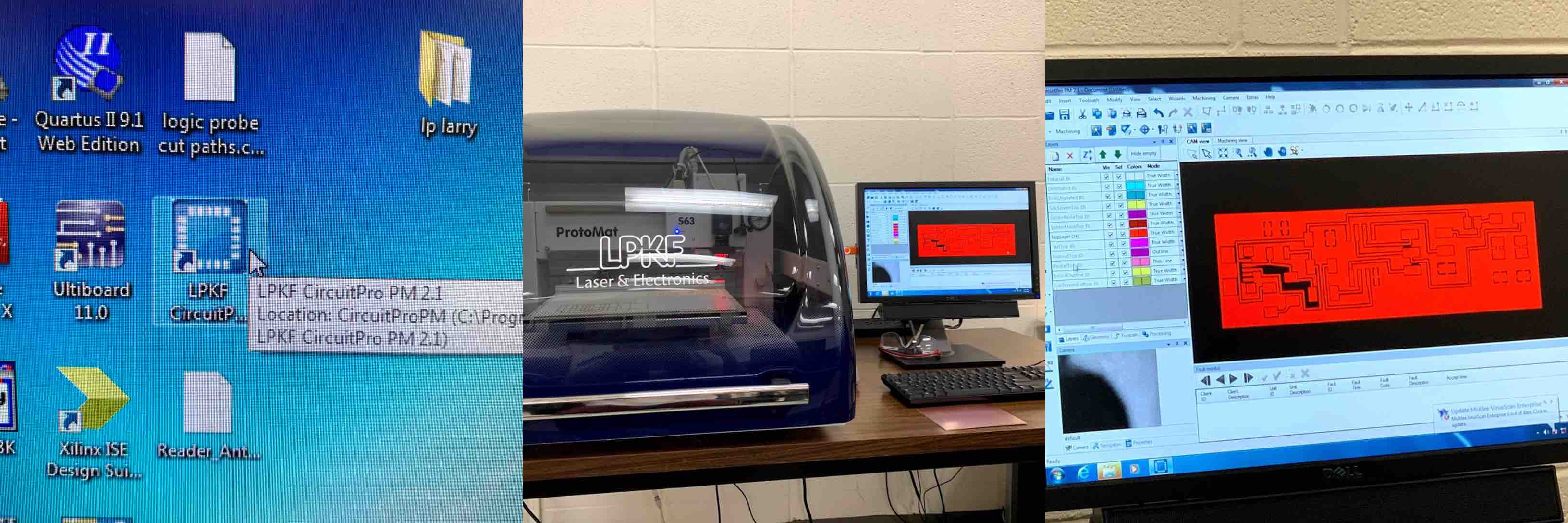
As a group we also worked together to upload our mill file. We stepped through the set up process. We had to import our file into the LPKF CircuitPro PM 2.1. The next step was to set up the machine tools. We set up our material size. We lifted the lid and loaded the material. The material was FR1 paper based board with a coating of copper. We used masking tape to adhere the FR1 to the mill bed. Between the mill bed and the material layer was a sacrificial layer.
- A sacrificial layer is a layer of material placed between the cut layer and the bed of the machine. This is done to protect the bed of the machine from fully routed lines.
Once our 4 inch x 6 inch piece of FR1 material was taped down we were able to begin the start up process of the mill. We had to be sure we homed the starting point.
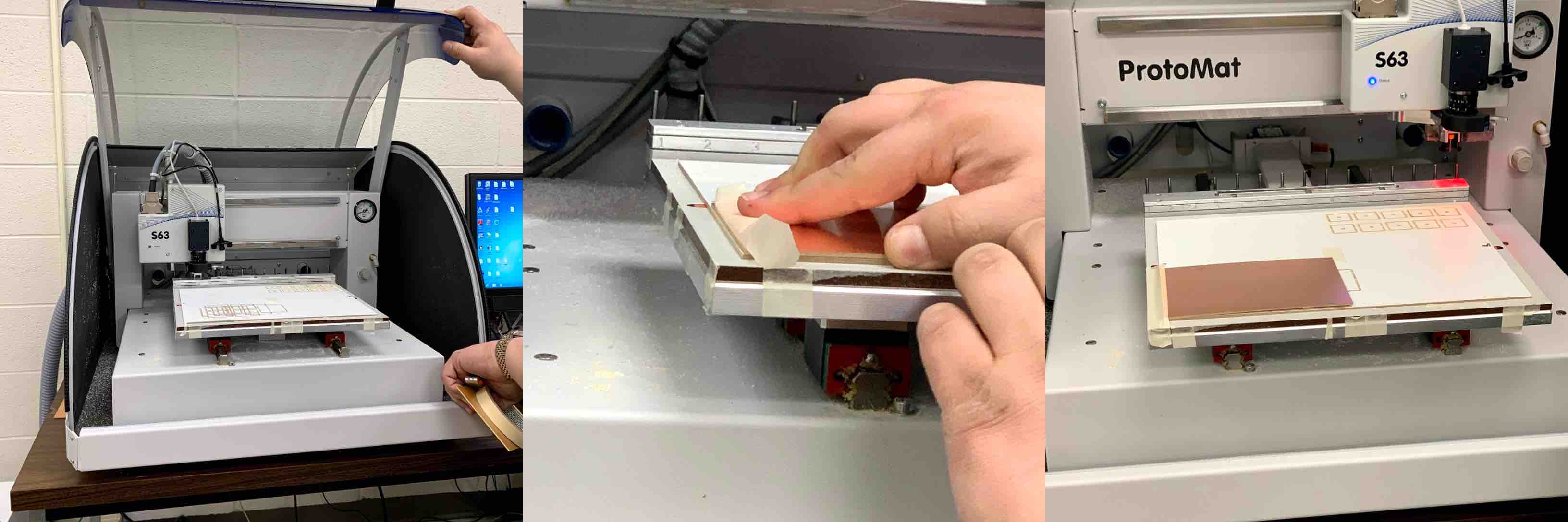
The mill was then started to run its program. The first time we ran the mill the board was not cut through. There was light etching in some places, but not enough to work with. We did some trouble shooting and were able to successfully cut 5 boards, one for each local student. The LPKF used a combination of V bits, end mills, and universal milling bits.