7. Computer Controlled Machining
Group Assignment
Test runout, alignment, speeds, feeds, and toolpaths for your machine.
Useful links to our Student Sites
- Alecia Gorski Fab Academy Site
- Christopher Leon Fab Academy Site
- Hallie Krudy Fab Academy Site
- Ryan Corrigan Fab Academy Site
- Sydney Richardson Fab Academy Site
Setting and Running the Machine
The Machine:**
Shopbot PRSstandard 4’ x 8’ computer numerical controlled (CNC) router
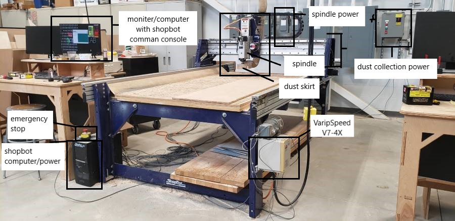
Safety:
- Closed Toed shoes
- No loose clothing or accessories
- Safety Glasses
- Hair tied back
- Emergency stop
- Never reach in when tool is powered
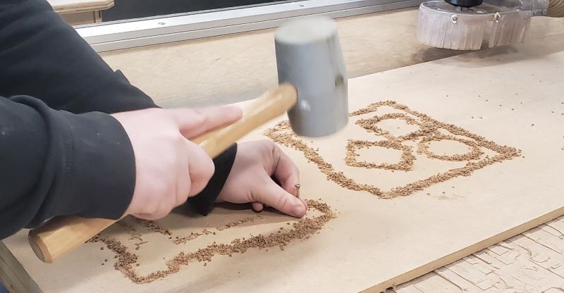
Secure the Material:
Position the material on the bed on the lower left hand corner, which has a sacrificial layer attached to prevent damage to the actual table bed.
Screw the positioned material down to the sacrificial layer using construction screws.
Use an impact driver to first drive the screws into each corner of the board, then screw down using a drill until the screws heads are flush with the top of the material.
(Before any actual cutting begins, if there are any pieces that could spin out, screw them down to the bed.)
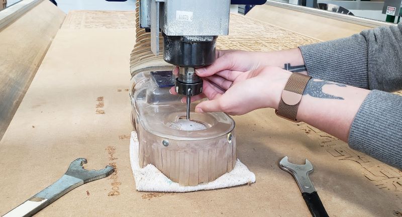
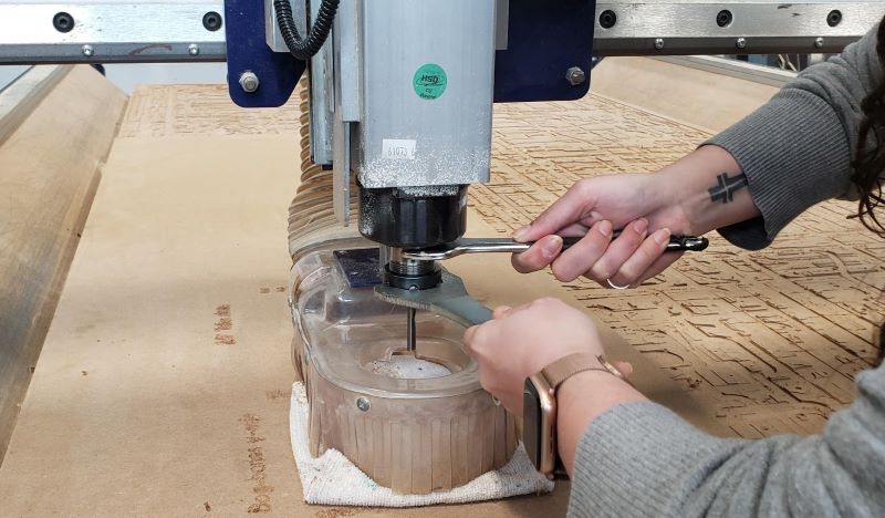
Load the Tool:
Acquire the correct tool bit, collet, and collet nut. In this case, a v-carve tool bit is being used.
Place a rag underneath the spindle. This will decrease damage in case of a tool dropping.
Start by removing the dust skirt by loosening the thumb screw at the back of the spindle.
Snap the collet nut and the collet together, then slide the new bit into the collet.
Carefully attach the collet-tool assembly to the spindle and hand tighten.
Fully secure by using the collet wrenches to tighten the collet.
Secure the dust skirt back onto the head.
Power the ShopBot:
Turn on the ShopBot by pressing the power button on the control box.
Manually Move the Spindle:
Click the yellow KeyPad icon in the red control screen. The KeyPad screen should appear.
Use the keyboard arrows to manually move the head, as close as possible, to the desired home location: Exit the KeyPad screen.
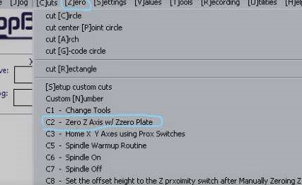
Zero the X and Y Axes:
In the ShopBot Command Console menu, click on Zero ----> Zero [2] Axes (X & Y)
Zero the Z-Axis:
Slide the touch plate out, located on the left side of the head, and place below the tool bit.
In the command console, click Zero, Zero Z-axis with Zero Plate.
The head should lower until the tool bit just touches the plate causing the head to lift up again.
Place the touch plate back into the holder.
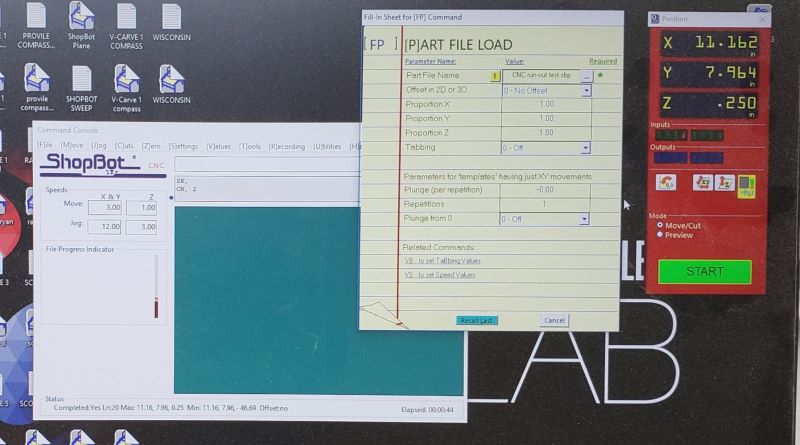
Load File:
Insert USB with file/s
In the command console menu, click File, Part File Load.
Select the desired file and open.
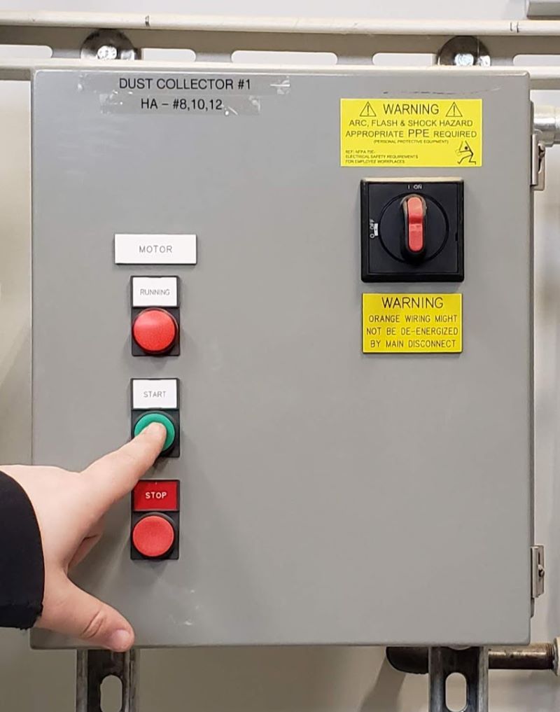
Turn on the Spindle Power and Dust Collector:
Flip the Spindle Power Switch, labeled ShopBot Lathe #2, upwards to activate.
Push the green button for the Dust Collector to turn on.

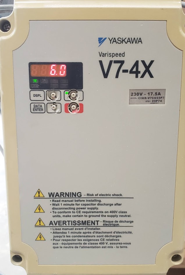
Turn on Spindle and Set Speed:
On the right side of the ShopBot is a box (VaripSpeed V7-4X) with a screen, use the middle set up buttons to set the speed.
Once set, push the green button to the right to start the spindle.
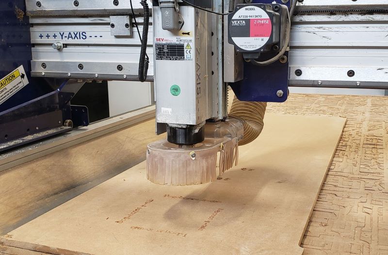
Run the File:
Have the emergency stop button in hand, and press “Start” to run the file.
If anything goes wrong, immediately press the emergency stop.
Once the file has run, the ShopBot will automatically stop.
Tool Change:
Stop the spindle by pressing the red button on the VariSpeed.
Turn off the spindle power, by flipping the spindle power switch down.
Turn off the dust collection by pressing the red button on the box labeled dust collection.
Acquire the correct tool bit. In this case, a quarter inch end mill is being used.
Place a rag underneath the spindle. This will decrease damage in case of a tool dropping.
Remove the dust skirt by releasing from the wing nut at the back of the spindle.
Loosen the collet by using wrenches and carefully remove the previous tool.
Load the new tool by sliding the bit into the loosened collet and hand tighten.
Fully secure by using the collet wrenches to tighten.
Secure the dust skirt back onto the head.
Repeat Zero of X, Y, and Z Axes:
Manually move to the desired home location.
In the ShopBot command console menu, click on Zero ----> Zero [2] Axes (X & Y)
Place the touch plate underneath the spindle and in the command console menu Zero, Zero Z-axis with Zero Plate.
Open New file:
In the command console menu, click File, Part File Load.
Select the desired file and open.
Turn on the Spindle Power and Dust Collector:
Flip the Spindle Power Switch, labeled ShopBot Lathe #2, upwards to activate.
Push the green button for the Dust Collector to turn on.
Turn on Spindle and Set Speed:
On the right side of the ShopBot is a box (VaripSpeed V7-4X) with a screen, use the middle set up buttons to set the speed.
Once set, push the green button to the right to start the spindle.
Run the File:
Have the emergency stop button in hand, and press “Start” to run the file.
If anything goes wrong, immediately press the emergency stop.
Once the file has run, the ShopBot will automatically stop.
Repeat as Necessary:
Four files were run:
Letters (V-carve) -------------------------------Tool change Runout (1/4th Inch End Mill) Mark (1/4th Inch End Mill) --------------------------------Screw loose parts Cut (1/4th Inch End Mill)
Finish and Clean:
Stop the spindle by pressing the red button on the VariSpeed. Turn off the spindle power, by flipping the spindle power switch down. Turn off the dust collection by pressing the red button on the box labeled dust collection.
Place a rag underneath the spindle. This will decrease damage in case of a tool dropping.
Remove the dust skirt by releasing from the wing nut at the back of the spindle.
Loosen the collet by using wrenches and carefully remove the collet. Place the tool, collect, and collect nut in the correct home.
Secure the dust skirt back onto the head.
Manually move the spindle out of the way of the material. Turn off the ShopBot.
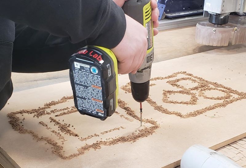
Unscrew the material and pieces using the drill. Remove the material and finished pieces.
Vacuum the area and clean up!
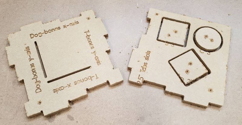
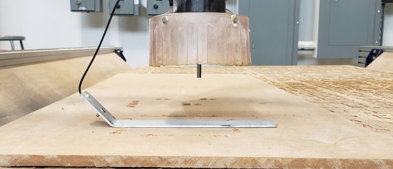
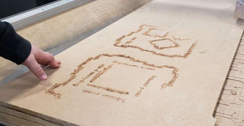
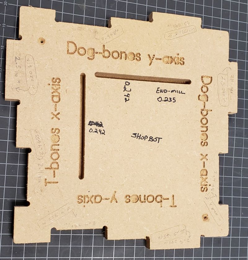
The Test
Chris Leon designed the test (above image) with a control. The test included T-Bones and Dog-Bones on the X and Y axes, square; diamond; and circle cutouts, lettering, and some straight cut lines.
| Settings | Conclusions | |
|---|---|---|
| Material | Medium density fibreboard or MDF | Prone to lots of dust and issues with lettering. No problem as there is the plywood material choice for individual |
| Tool Bits | V-carve and 1/4th inch end mill | Tool radius was undersized (measured at 0.235 inches.) |
| Speed | 6000 RPM | This was a |
| Feed Rate | 150 in/min | The feed rate will depend on material, tool radius, and speed, so adjust as needed. |
| Plunge Rate | 50 in/min | Depends like the feed rate. |
| Ramp | 2 in | |
| Cut Depth | 0.13 in |
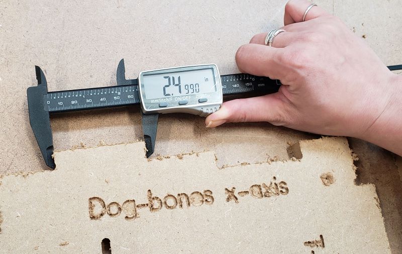
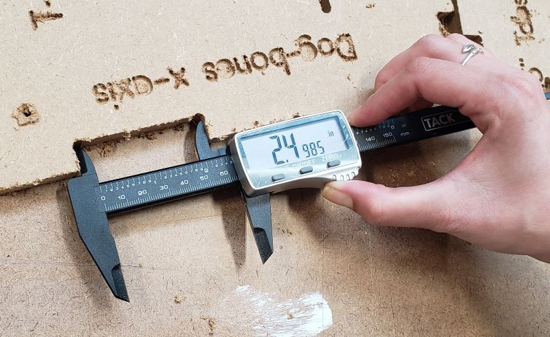
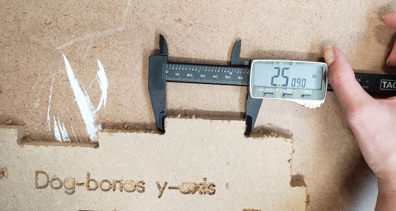
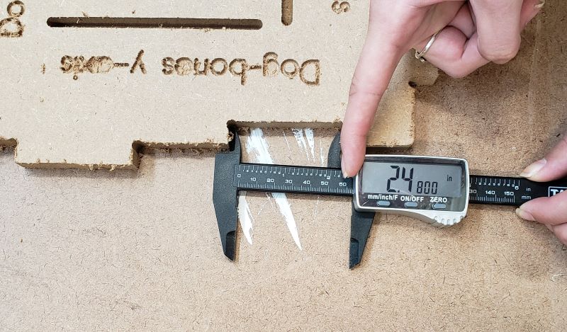
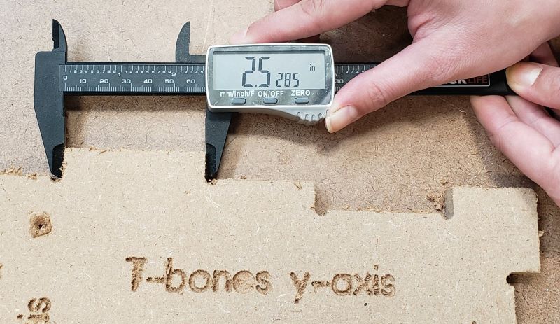
Dog-Bones
Dog Bones are a type of transition that helps avoid rounded corners caused by the tool. The transition is named so as to the similarity in shape to a dog bone.
X-Axis
The dog-bones measured at 2.4990 inches (tab) and 2.4985 (slot).
Y-Axis
The dog-bones measured at 2.5090 inches (tab) and 2.4800 (slot).
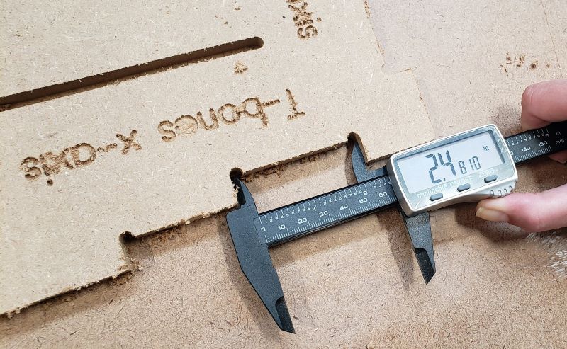
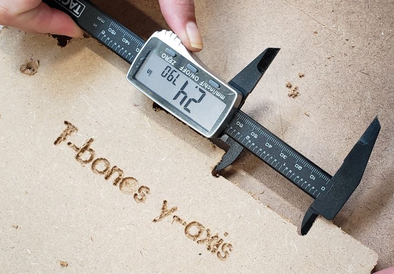
T-Bones
T-Bones are another type of transition that forms a “T” shape at the ends.
X-Axis
The T-Bones measured at 2.5140 inches (tab) and 2.4810 inches (slot).
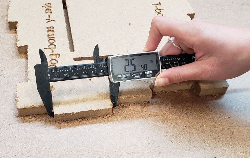
Y-Axis
The T-bones measured at 2.5285 inches (tab) and 2.4790 (slot ).
Conclusions
The inconsistency within the dog-bones and T-Bones were due to the undersized quarter inch end mill, as was found out later when the tool was measured. Due to the undersized nature, the tabs and slots were not milled correctly. In individual projects, a half-inch end mill will be used, which has been measured to be exactly 0.50 in; this will ensure accurate and more precise results.
Line Test for X and Y Axes
The width was measured to be 0.242 inchesfor both the x-axis and y-axis. This was caused by the undersized quarter inch end mill (0.235 in). The kerf is then 0.007 inches.
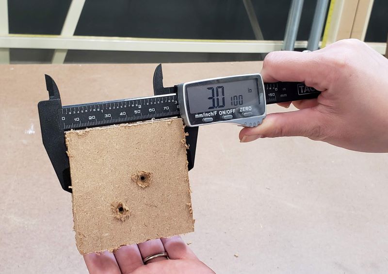
Square, Diamond, Circle
Square
The square’s sides measured to be around 3.0140 inches, only differing by around a few thousandths of an inch.
Diamond
The diamond’s sides measured to be around 3.0100 inches, only differing by a few thousandths of an inch.
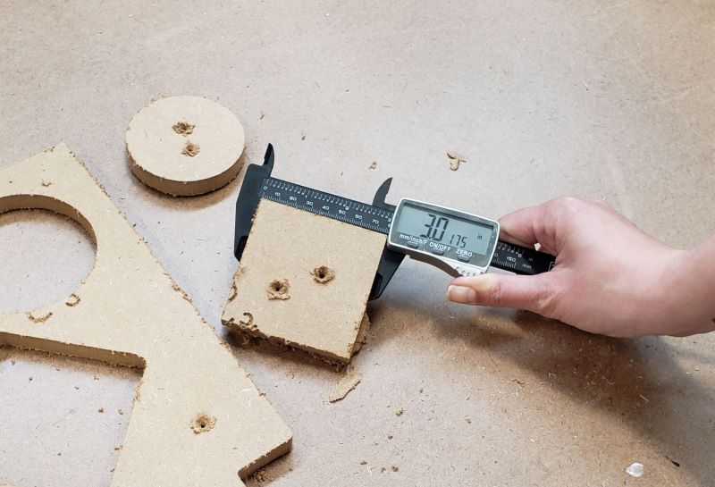
Circle
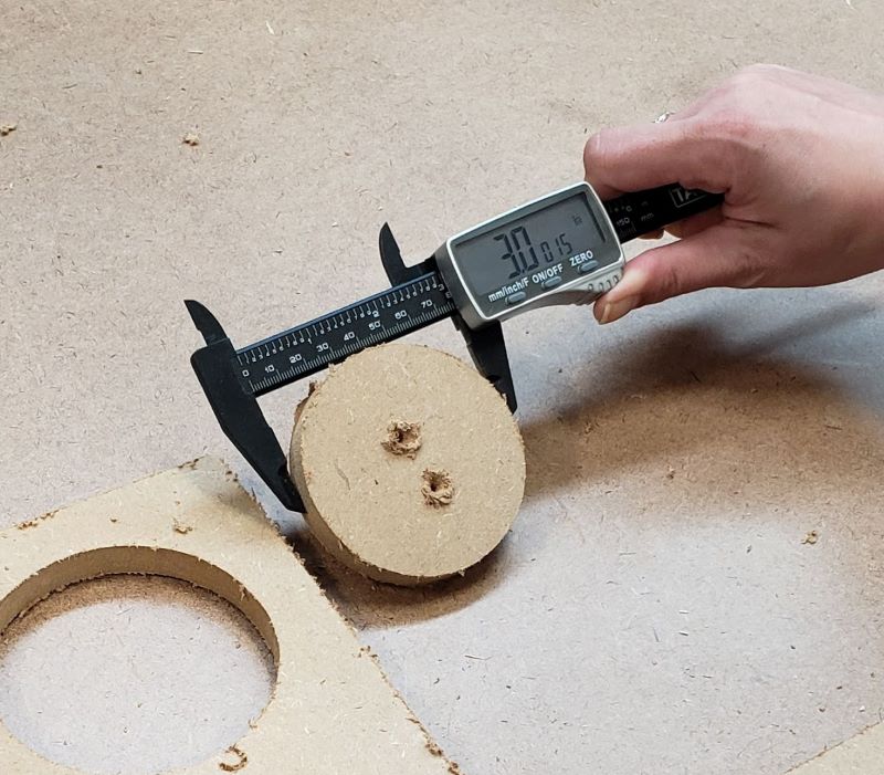
The circle’s diameter measured around 3.0015 inches, differing by a few thousandths of an inch each time measured.
Conclusions
The shapes were all consistent in their side lengths meaning the ShopBot alignment is good.