3. Computer Controlled Cutting
The group assignment this week was focused on getting to know our laser cutter and vinyl cutters. Our lasers are from Epilog and our vinyl cutters are from Roland.
Useful links to our Student Sites
- Alecia Gorski Fab Academy Site
- Christopher Leon Fab Academy Site
- Hallie Krudy Fab Academy Site
- Ryan Corrigan Fab Academy Site
- Sydney Richardson Fab Academy Site
Group Assignment
- Characterize your lasercutter’s focus, power, speed, rate, kerf, and joint clearance
Laser Kerf
Defined by the dictionary Kerf is a slit made by cutting with a saw.
Defined by our class Kerf is the measurement of material removed as a result of a cut. - This can be in the laser cutter, the CNC routers and saws we have at our location.
For the group project we focused on the Kerf determined by our laser. We were challenged to use cardboard (that bows not crimps) to create a construction kit. In order to complete this we needed to know how our laser would react to the cardboard. It is important to understand how much material will be removed from the Kerf of the laser.
The kerf is not only the spot where the laser makes contact to the material, but also the area around it radially. When applying heat to a material there are many things to consider. The amount of material removed is one of them.
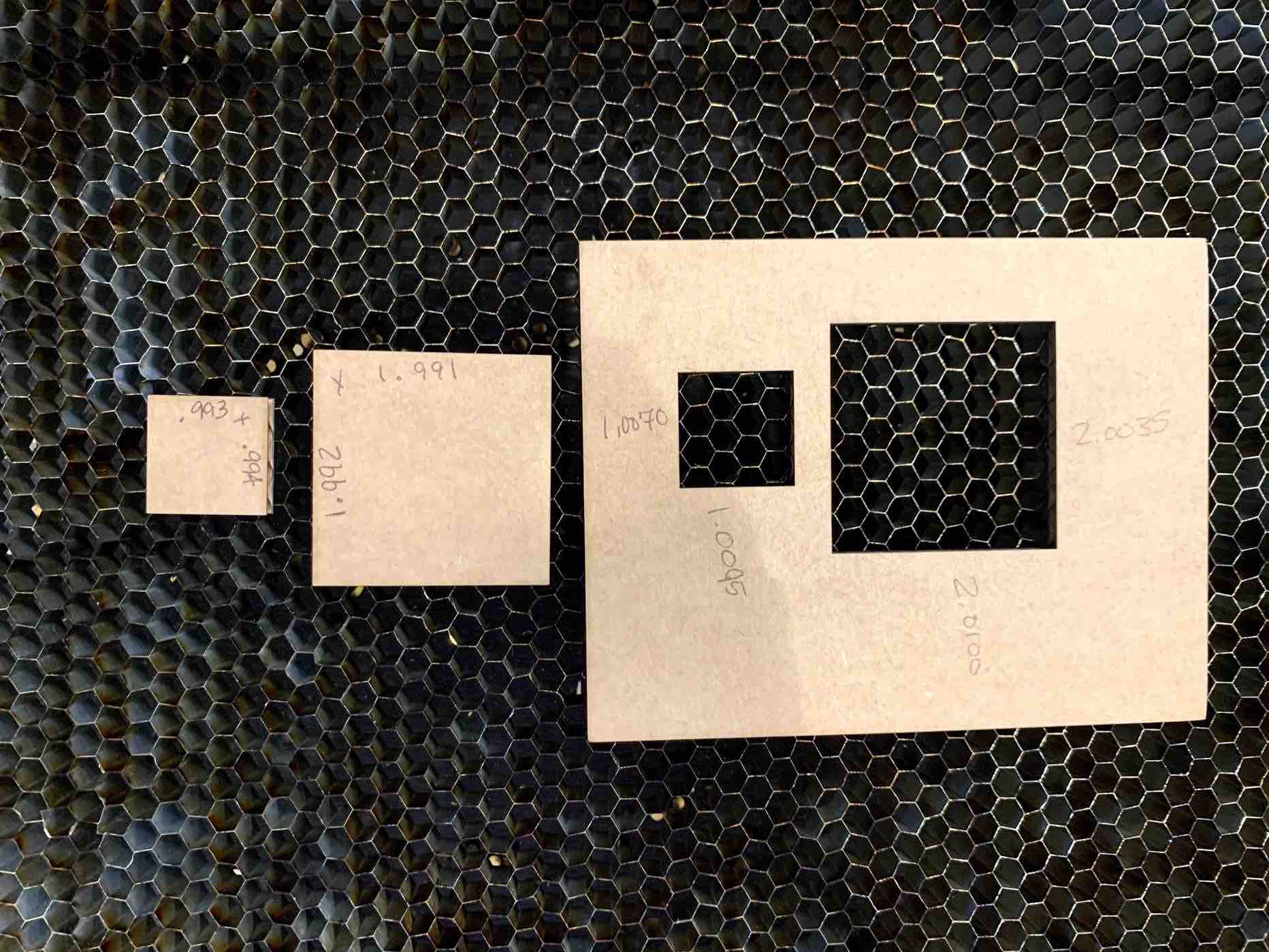
The kerf will very not only by material but by machine as well. The wattage, the bed level and the laser settings can all affect Kerf. In order to measure the Kerf we picked two squares. We made one measure 1in x 1in and the second measure 2in x 2in. We decided to do two shapes so we could compare the Kerf and so we could have a good average of the material. Even just from the top of the cardboard to the bottom could result in a change on Kerf.
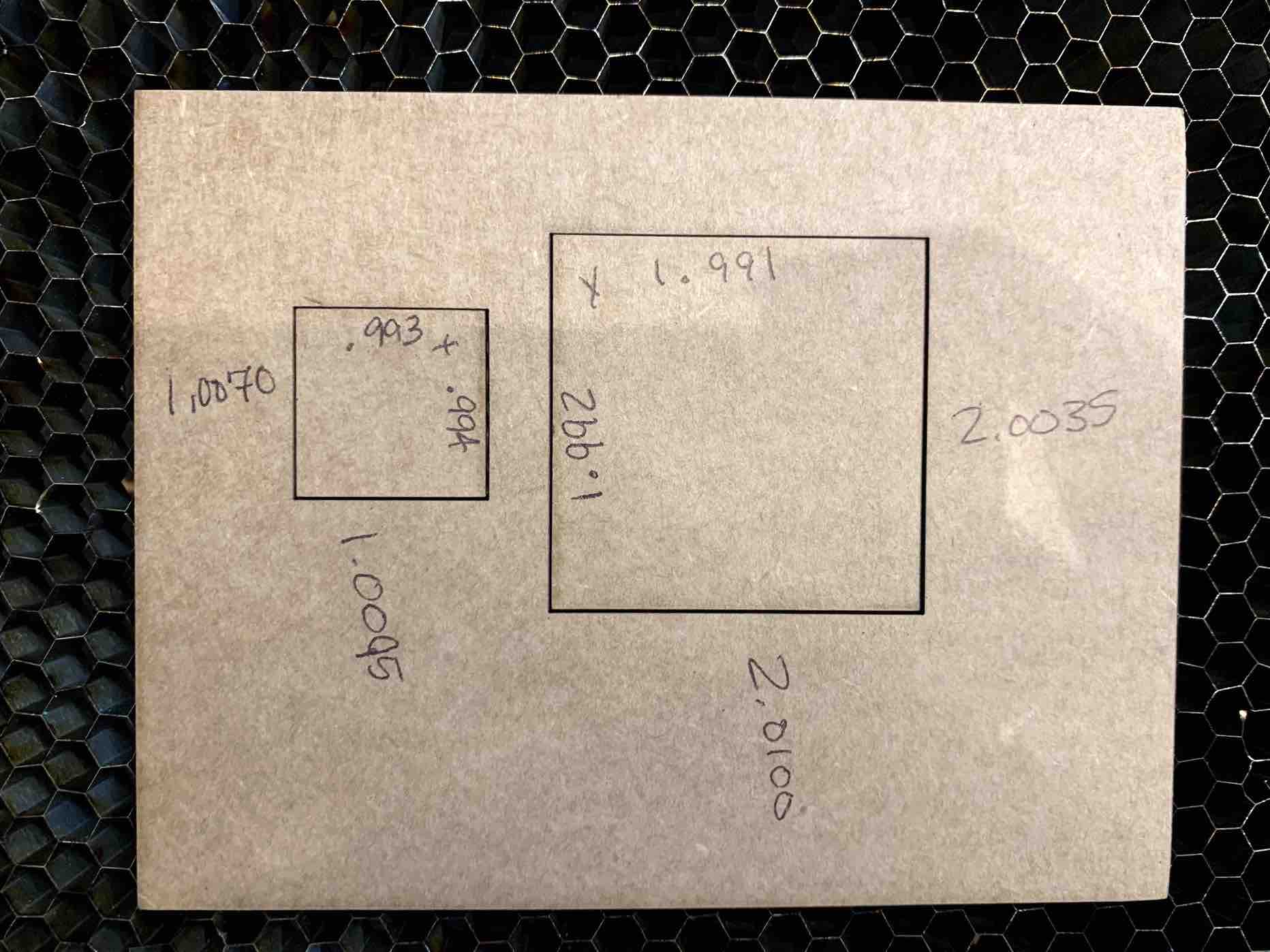
- The 1in x 1in square resulted in a kurf from the top to bottom equal to 0.0165. The kerf from left to right is equal to 0.013. This results in an average of 0.01475.
- The 2in x 2in square resulted in a kurf from the top to bottom equal to 0.019. The kerf from left to right is equal to 0.0115. This results in an average of 0.01525.
- Overall this results in a total average of a Kerf = 0.015
Laser Joint Clearance
For better understanding of joint clearance it is simply the space between each joint where they meet. To be sure we had the correct set up for our options we started by measuring the thickness of the material we decided to use. This gives us a good starting measurement. Each material change, and even between pieces of the same material, can result in differences. Checking joint clearance each time is important to be sure your pieces connect well.
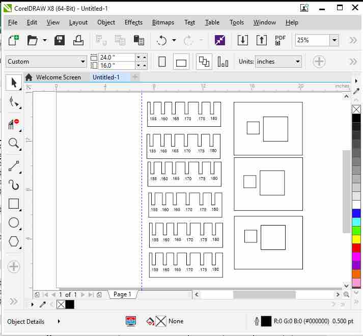
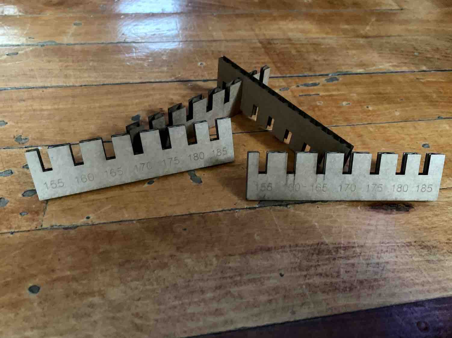
We used the certified cardboard that was suggested. We have large sheets so they were cut down to 18 inches x 12 inches to fit into our Epilog Laser. When the cardboard was ready we created a document on the computer using CorelDraw. This document was created to try multiple joint clearances in the same piece, centered around the thickness we attained by measuring the cardboard with a caliper. - It is important to check your caliper readings more than once and use an average. How you take the reading can provide you with different results.
Once we determined that the thickness of the cardboard was between .167 in and .170 in we were ready to work on our design. We created a box using the rectangle tool in CorelDraw. We then created multiple other rectangles to represent the tabs in the joints. Once they were created we flowed in place holder text to represent how each tab would be labeled. When each measurement was correctly labeled we then changed the width of each tab representation to match the thickness listed.
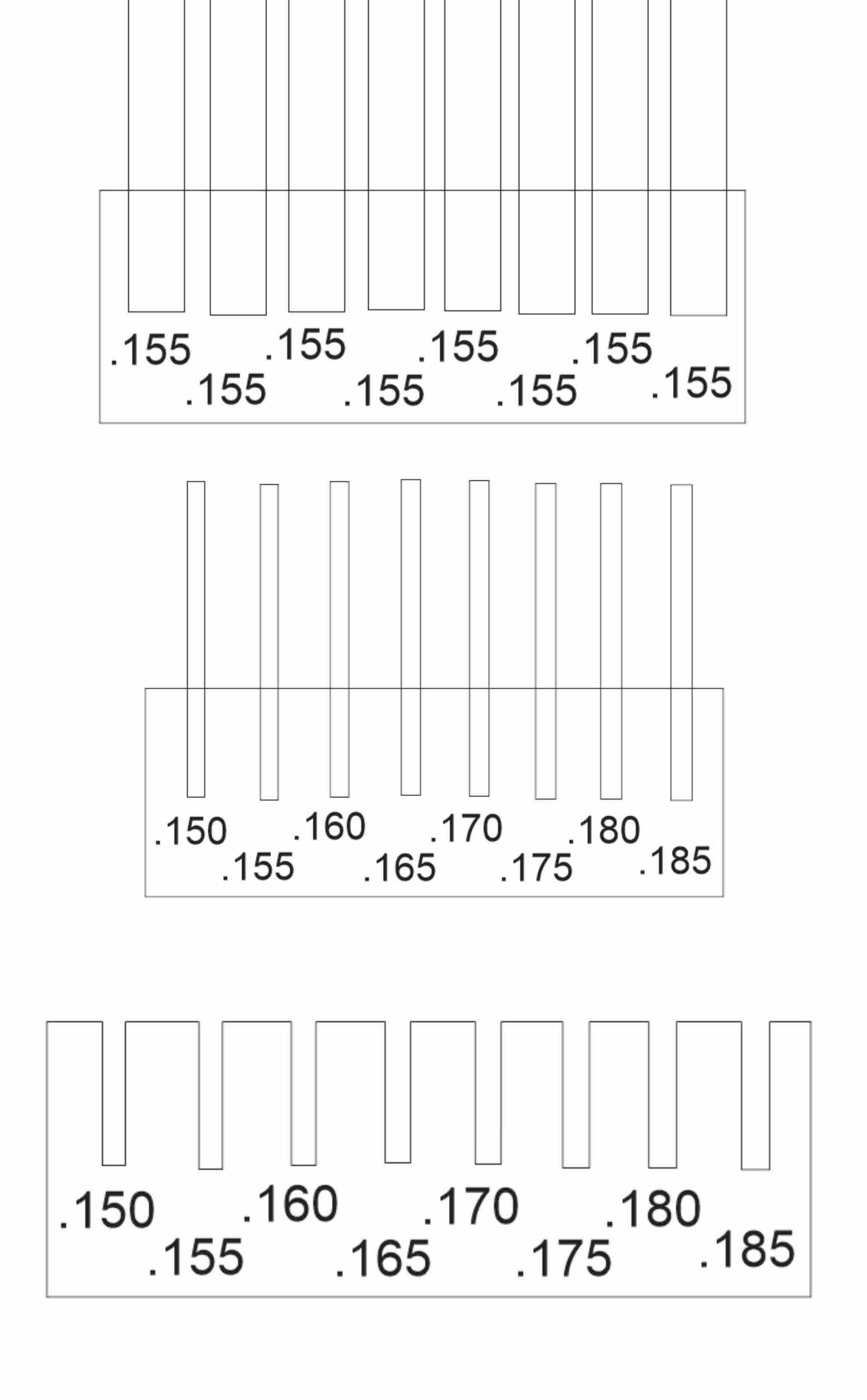
Once all the measurements were correct we then used the segment delete tool (the segment delete tool is located in the tool bar on the left side of CorelDraw, it looks like the slanted edge of a blade with a white minus sign inside a red circle.) Making sure to remove the rectangles exceeding the main box, and the line where the intersect. This created our tabs and joints. - Keeping in mind the measurements used in our test were .155 in, .160 in, .165 in, .170 in, .175 in, .180 in and .185 in. These measurements were based off of the thickness of our measured material and included measurements both smaller and larger in order to determine the correct thickness per tab.
Once our deign was created we set the preferences for our material we sent it through to our laser.
The first gray screen represents our setting. This screen is where we choose which machine we would like the print driver to use. After selecting Epilog Matilda we chose the Preferences box located to its right. This provided us with our setting screen that tells our laser what to do. Turning our job type to combined allowed us to use both the raster and engraving settings. We wanted to raster our labels and cut our shape. Using a sheet of cardboard that fit our laser we set our piece size to 24 in x 18 in. We then set our raster and vector cutting settings.
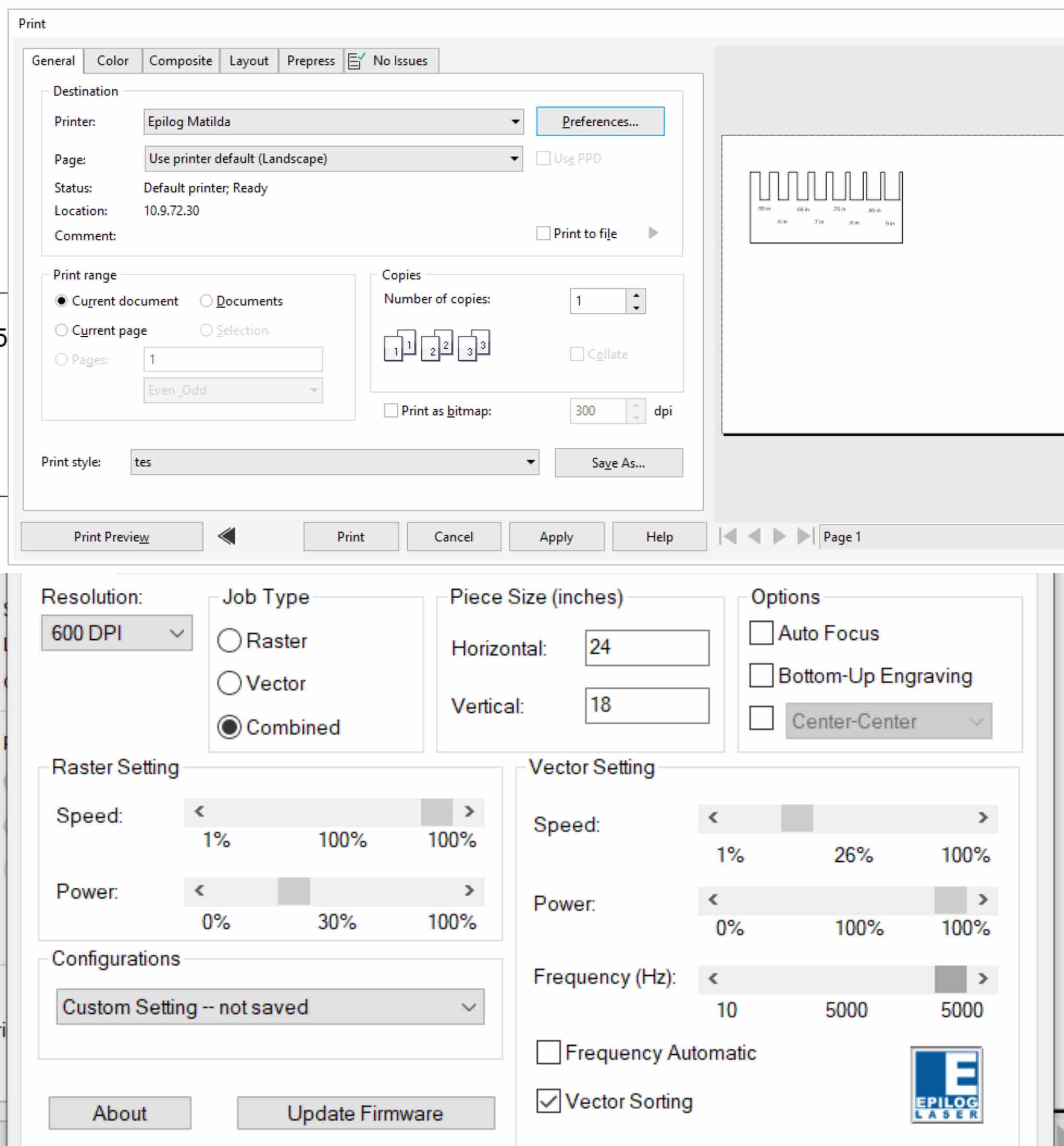
Once our settings were loaded into the print driver and our material was loaded into the machine we completed the focusing steps on our laser. We made sure that our CAD file included both the joint clearance test and the kerf test for the laser. We sent our job to the laser when it was complete. We then pressed Go (the green button located on the laser screen). This began our cutting process and provided us with our final results. From here each group member was provided with their own set to determine which setting they would use on their construction kit.
Laser Focus
Before use with the laser, it must first have the focus set. The focus changes based on the material thickness. The laser can engrave on any thickness that will fit the bed when lowered completely. However, the laser is only powerful enough to cut all the way through material up to .25” thick. The stronger the laser the thicker the material it can cut.
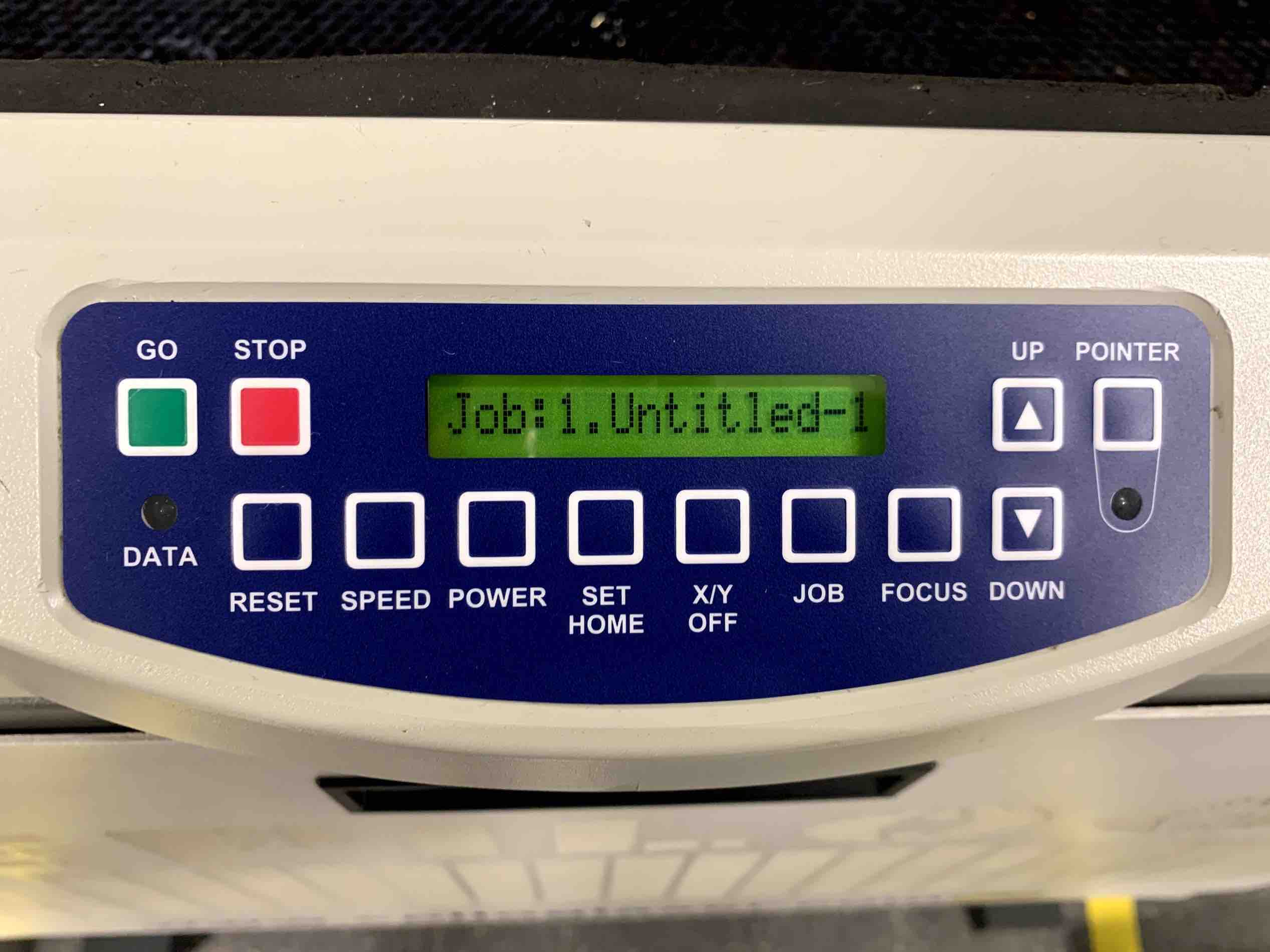
To set the focus the user should first press the focus button seen on the display pad.
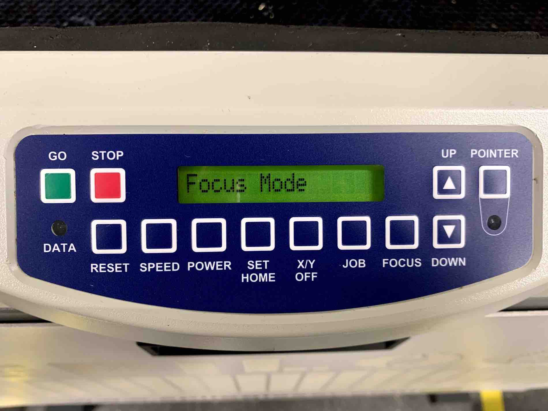
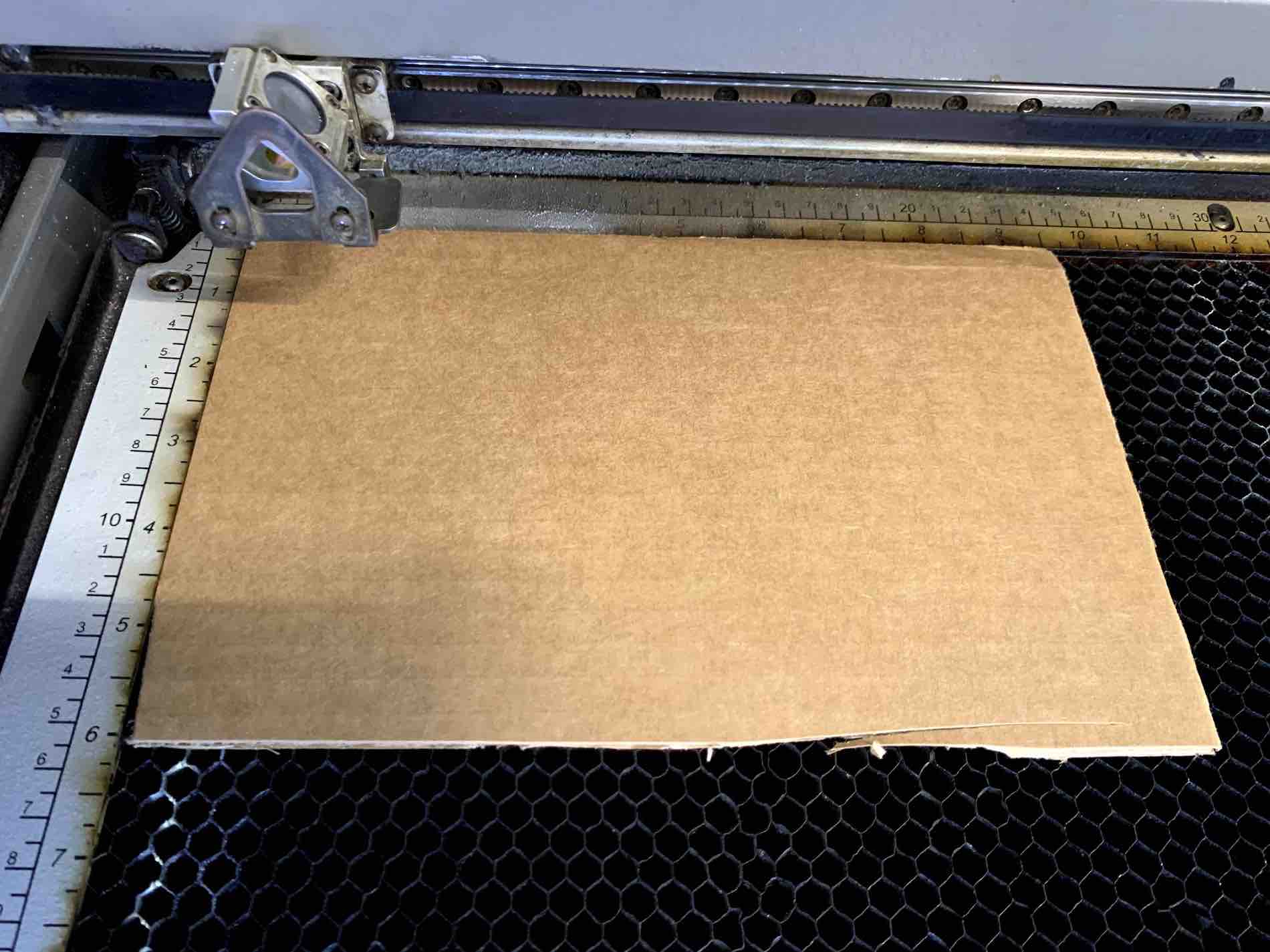
Once the laser enters focus mode the user can use the arrows on the display pad to drop the bed. This is important to do before material is placed on the try. Be sure to lower the bed at least 2 inches lower than the thickness of your material. This is called the focal length of the laser. Place the material onto the bed. Using the arrow stored above the laser flip it over and store it back on the pegs so that it is pointed down towards the material. This arrow length should always be equal to the focal length of 2”. The user can now raise the bed using the arrow that points up on the display pad. Raise the material so that it sits just below, but without touching, the arrow.
![]()
Now that the material is the correct distance from the laser the user can remove the arrow and store it correctly above the laser.
Press the reset button to leave Focus Mode. The laser is now ready for the lid to be lowered and the job run.
It is important to keep a correct focal length with each material. The Speed, Rate and Power are all based off of the laser being 2 inches from the material. If the material is too close it could be stronger than intended and possibly start a fire. If the material is further from the laser it may not be strong enough to work.
Laser Speed, Power & Rate
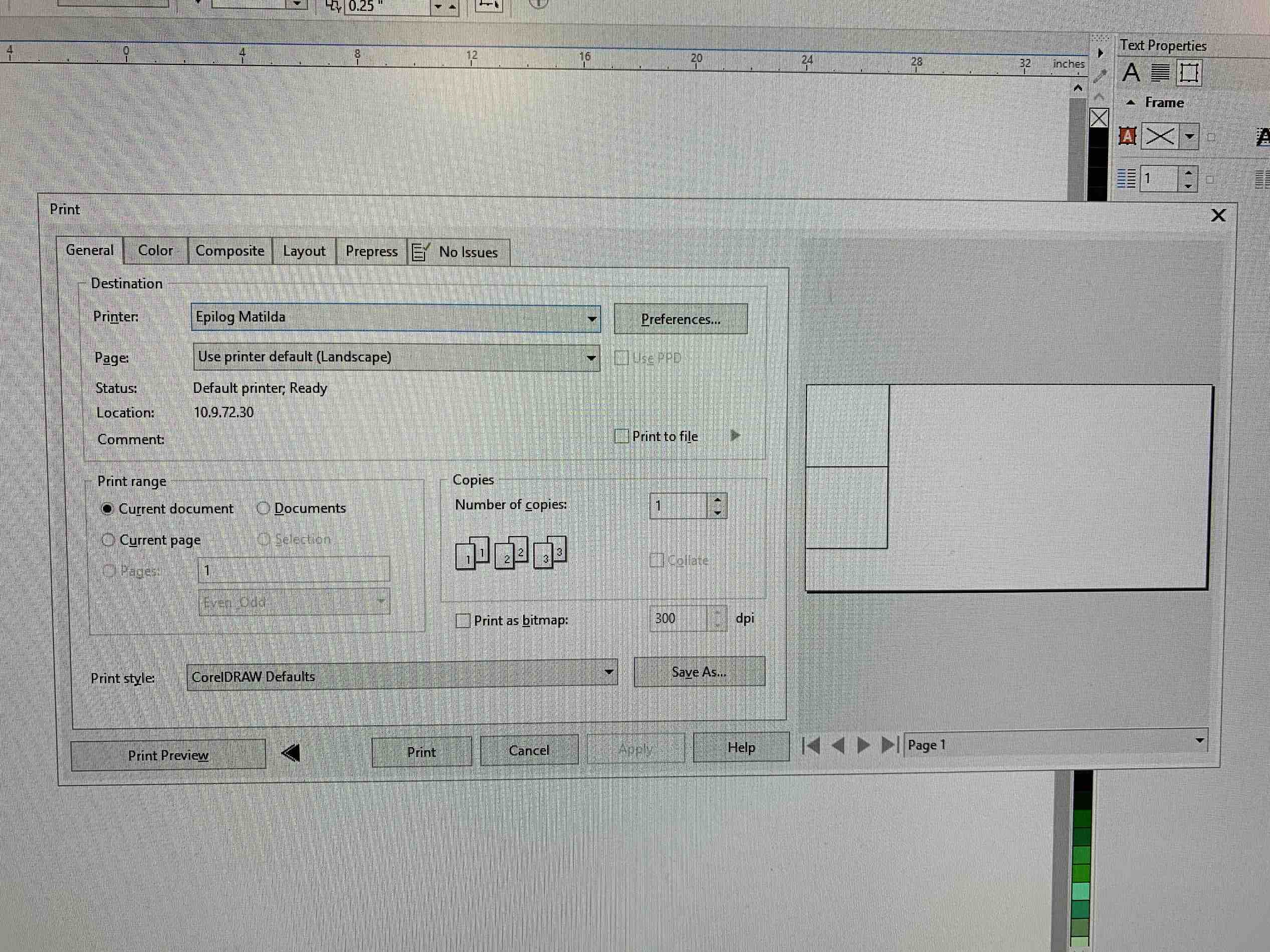
When using a CAD software to create the design you want to communicate with the laser you must have a print driver. The print driver will allow you to apply the correct settings to the laser in correlation with the material being used. To access the print driver the program you are using, such as CorelDraw, will have a print dialog box.
The print dialog box will provide you with a preview of your design, an option to change printer, along with many other fine tuning adjustments. For this assignment the Epilog Matilda was used. By selecting the Preferences button next to the printer chosen a print driver menu will pop up.
The print driver is shown as a blue box with different controls available. There will be settings on the right side of this driver that allow the user to adjust the Speed, Power and Frequency for both Raster and Vector. These are also known as the Speed, Power and Rate.
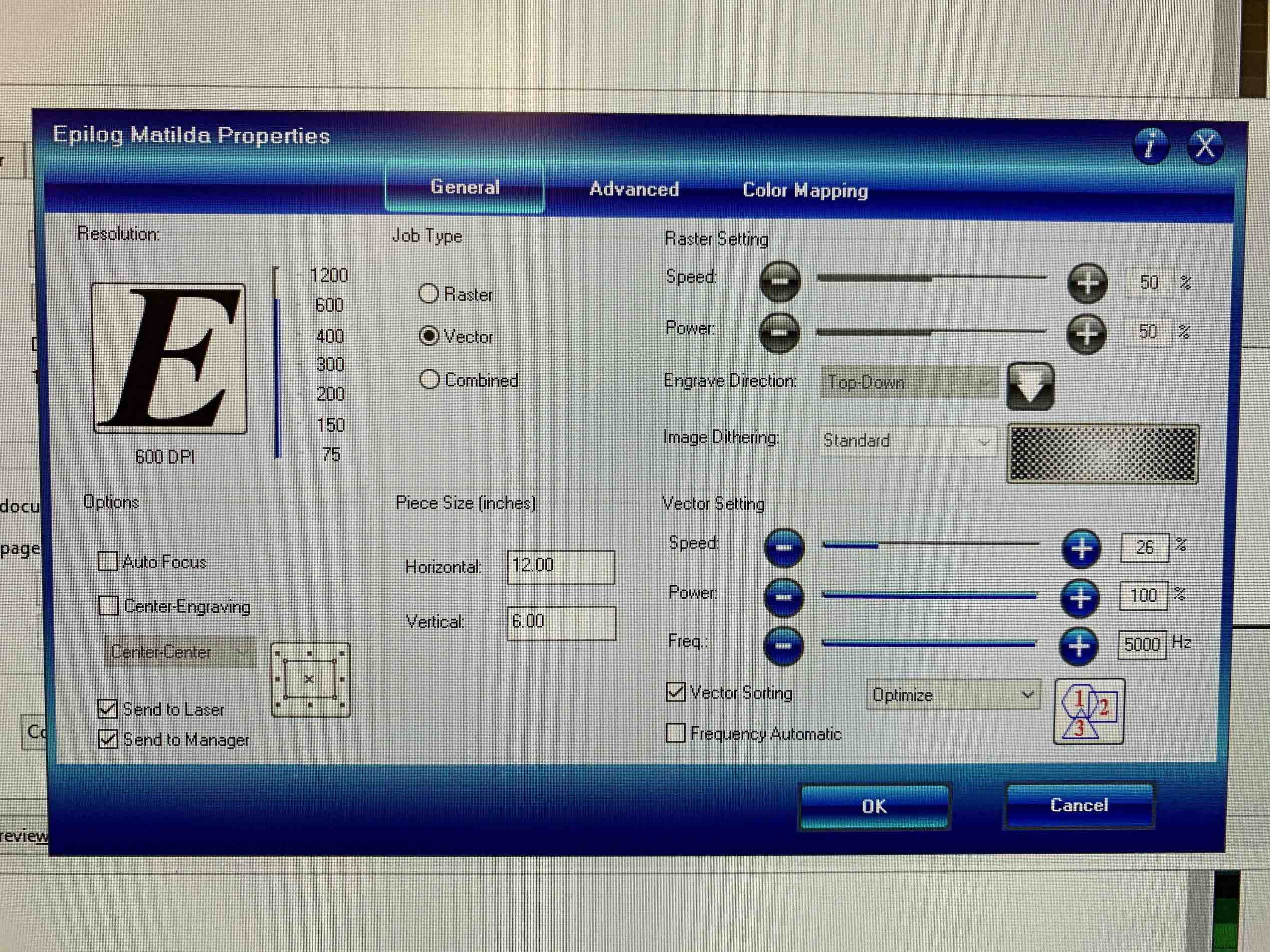
The Speed of the laser determines how fast the laser is moving on the X and Y axis of the machine. This is important to adjust based on the material being used. If the rate is too slow it could stay in the same position for too long and possibly start a fire. If the speed is too slow the material may show no engraving what so ever.
The Power of the laser controls how strong the laser is being emitted. This is really important to set correctly. If you place cardboard in the bed of the machine and use the settings for wood it would be very dangerous and could potentially start a fire. This is due to the density of the material. Wood is much more dense and compact than cardboard. If the laser power is being emitted stronger into the cardboard it will apply more heat to the area that has less material strength to withstand it. This will cause a physical reaction resulting most likely in a fire.
The Rate, or Frequency, of the laser controls the number of pulses per second. This can effect quality of the print and edge sharpness after cutting through a material.