3. Computer Controlled Cutting
This week I worked with Computer Controlled Cutting machines such as an Epilog Laser Cutter and a Roland Vinyl Cutter.
Research
The research conducted this week was based off of trial and error with the machines. We were challenged to complete a group assignment that reflected our testing on the laser cutter, as well as completing a personal construction kit that could be assembled in different ways. Each part was to be constructed with parametric constraints. We also were asked to create something with the vinyl cutter.
Group Project
On our group site you will see our findings. While working together we determined the laser cutters focus, power, speed, rate, kerf, and joint clearance. We used the suggested corrugated cardboard sheets that bow not crimp.
My contribution to our group project was to determine the kerf of our laser. The kerf of the laser is the amount of material that is being removed by the laser itself. When the laser applies heat to the material strong enough to cut all the way through, it then eliminates some of that material. To help visualize think about it as a beam of light coming from a flashlight. The middle of the beam is the strongest part but as you move radially from the inside out the beam gets weaker. This is the same with the laser. The middle of the beam takes the most material, however there is still additional material being removed radially. This means we must keep a few things in mind when experimenting.
- Each material will have a different reaction to the laser. Therefore each material will result in a different kerf.
- The kerf can very from spot to spot in the laser itself.
- The material may have slight variations on properties across the piece as a whole that may also effect your kerf.
My other contributions to the group page is the sections on Laser Joint Clearence, as well as the focus, laser speed, power and rate.
You can review this process in more detail on our group site found at the link below. There you can also review the results of the kerf test run at our lab.
Individual Assignments
This week I completed two different individual projects. I create a parametric construction kit that can be assembled in different ways. I also created a decal with the vinyl cutter for my laptop.
Laser Cutter
Idea from Brain to Paper
This assignment was particularly challenging to me. I have little experience with 3D design software or parametric designing. There are a lot of parameters I needed to keep in mind in order to complete a kit that would assemble smoothly, hold together and create different shapes or forms.
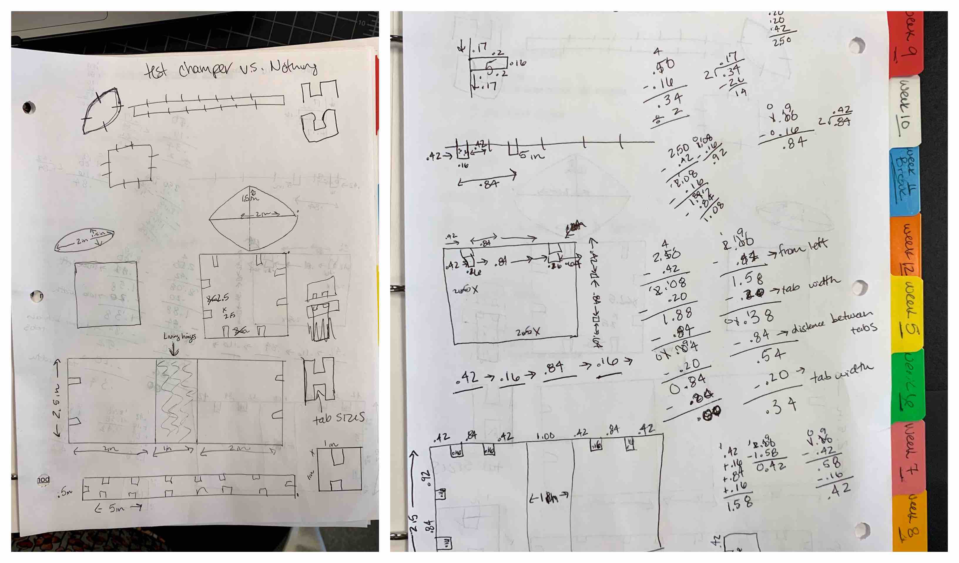
To start I decided to construct my pieces in Fusion 360. However, I could not easily imagine how I wanted my pieces to look. I was finding it challenging to start with the modeling step right from the beginning, so I decided to go to pen and paper. With a little time I was able to sketch up my whole plan. I created basic drawings of each piece, created them dimensionally and even did the math to be sure my tabs would be created in the right place.
Modeling in Fusion 360
When I began to model my pieces I started with the organic leaf shape. I had previously created a shape similar to this when I modeled my final project idea. I found it to be a challenge so I decided to use that shape again. I became more proficient with Fusion 360 in the process. I began a new admin project and started by creating 5 new component place holders for each of my designed pieces.
Leaf Design
- I started by creating a sketch on my origin plane while in my first component working tab.
- With the three point arc tool selected from the options, pulled up by my hot key S, I placed my first point at the center of my plane. The next point was placed directly across the plane at 2 inches. This represents the length of the piece created. This allowed me to then place my center point of the arc represented by a third point. I set this third point to .75 inches into the lower half of the plane. My bottom arc of the shape was completed.
- I repeated the process to create the top half, using the same starting point and length point. However, for the third point to create the arc in the right direction I placed it .75 inches above into the upper levels of the plane. This created my leaf shape with the measurement of 2 inches long and 1.5 inches wide.
- I selected the face of my shape and extruded it to represent the thickness being used for these parts and previously determined in the group process above, equal to .16 inches. My basic shape was then complete.
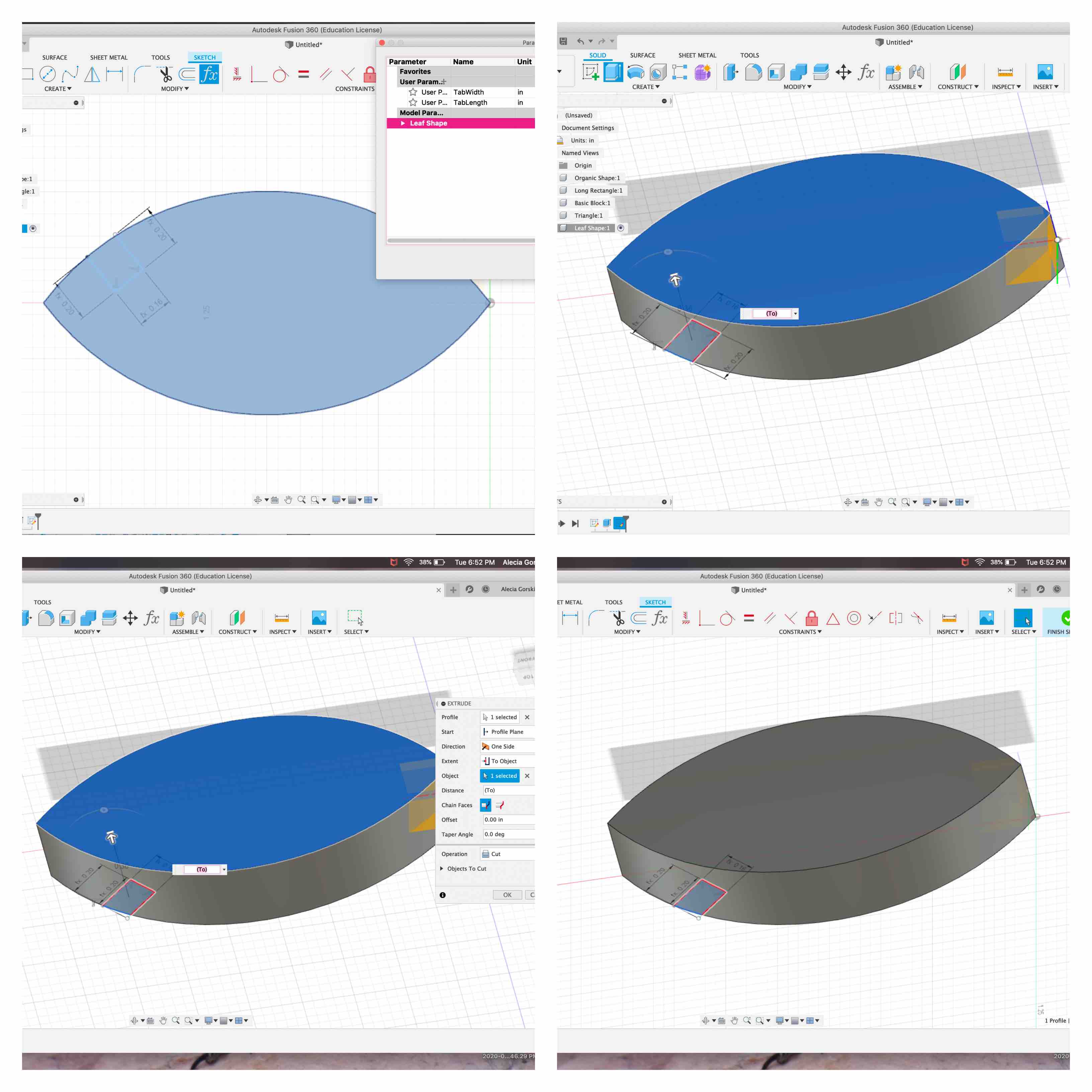
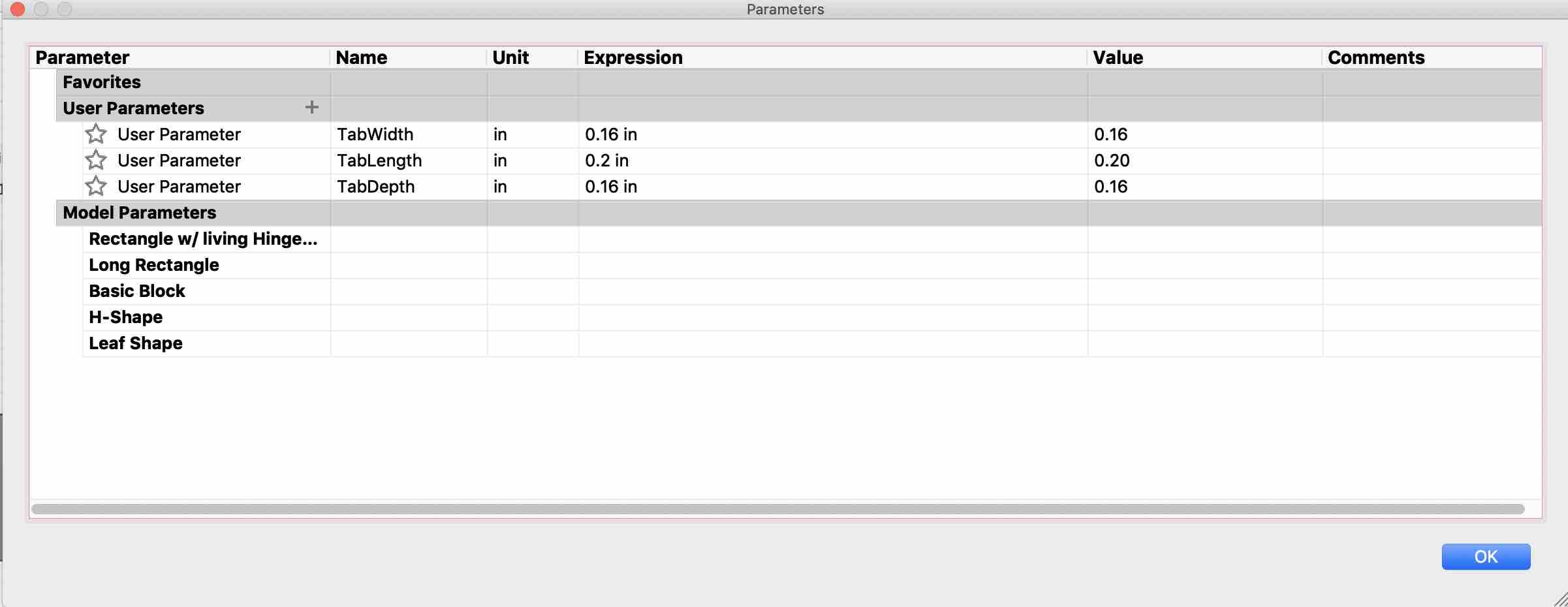
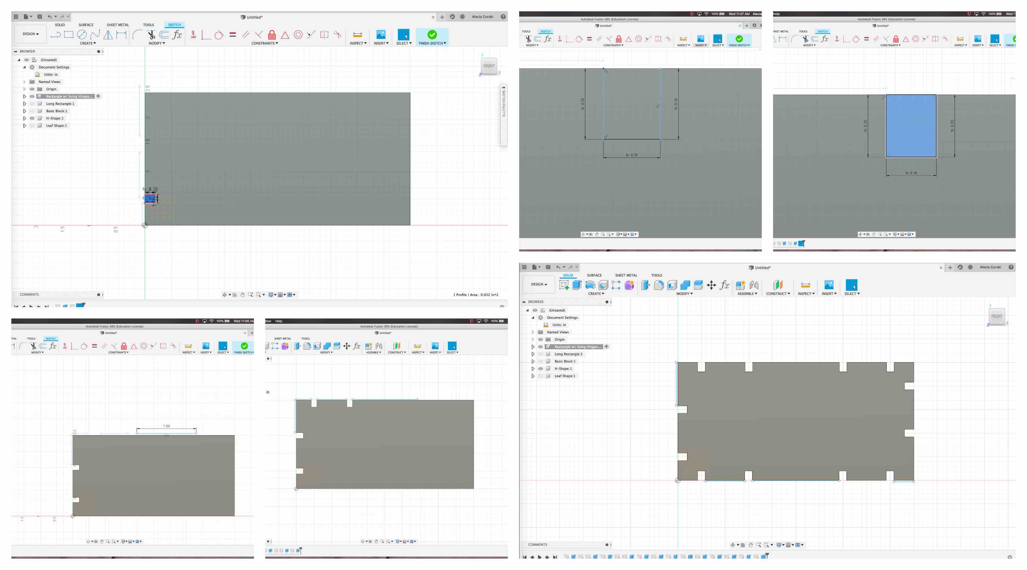
- Before I could move on to the tabs I had to start by setting my parameters. In the depiction below you can see that I have 3 parameters. These three parameters are how I control my parametric aspect of this project. Below my three set User Parameters are the Model Parameters. All 5 of my components are listed. This is because I have applied my parameters to each of these components. If my tab length needs to change, I change it in my parameters and it adjusts all locations. The same is done with tab depth and tab width. If my material size goes up I can adjust this to represent the new materials physical properties such as thickness. This will be demonstrated further later in my report.
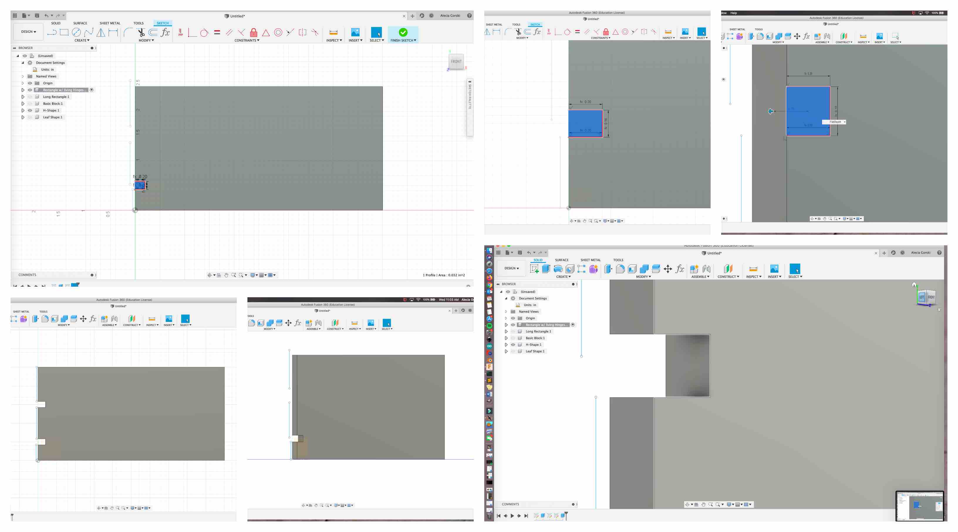
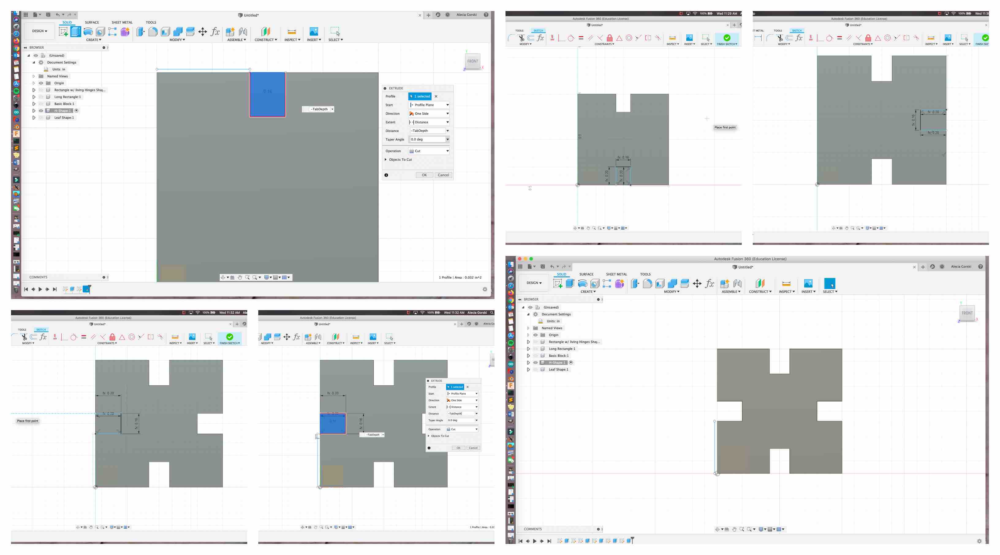
- I then began applying the tab parameters through each of the 4 locations desired. I started each time by creating a sketch on the face of my leaf. I used the hot key S to select my line option. With my line option chosen and my math completed in my sketches I then began by placing the first point of my line on the edge of the shape. For the length I typed in the selection box “TabLength”. It automatically applied my parameter at the predetermined length. I then began another line off of this one at a 90 degree angle and for the length I typed “TabWidth” into the selection box. This pulled from my parameters once again. To complete my tab shape I repeated the first step and placed my line at another 90 degree angle from the one previous. This created a face the shape of a rectangle but extended slightly on one side off the side of my leaf. This may seem odd, but it did not effect my design or desired tab structure.
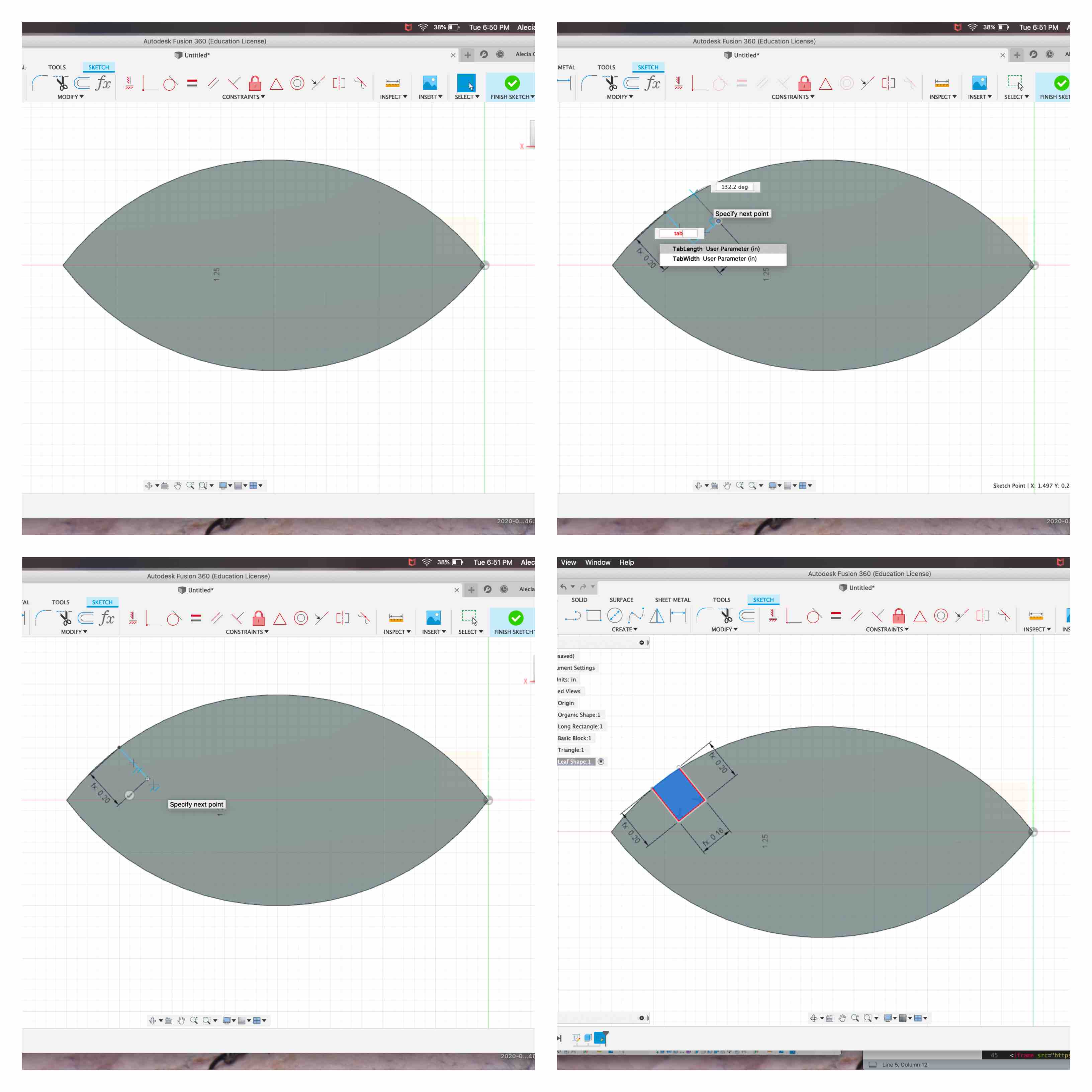
- This allowed me to select the blue face of the rectangle I had just created. Once selected I used my hot key Q to extrude the tab depth. When I typed “TabDepth” into the dimension box it used my previous parameter of .16 inches and extruded all the way through.
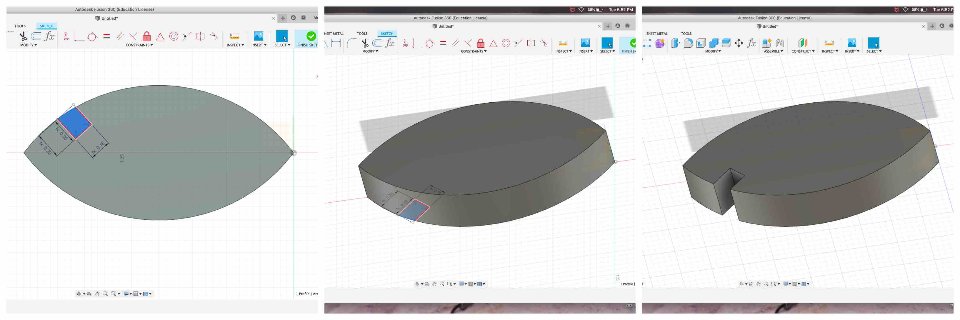
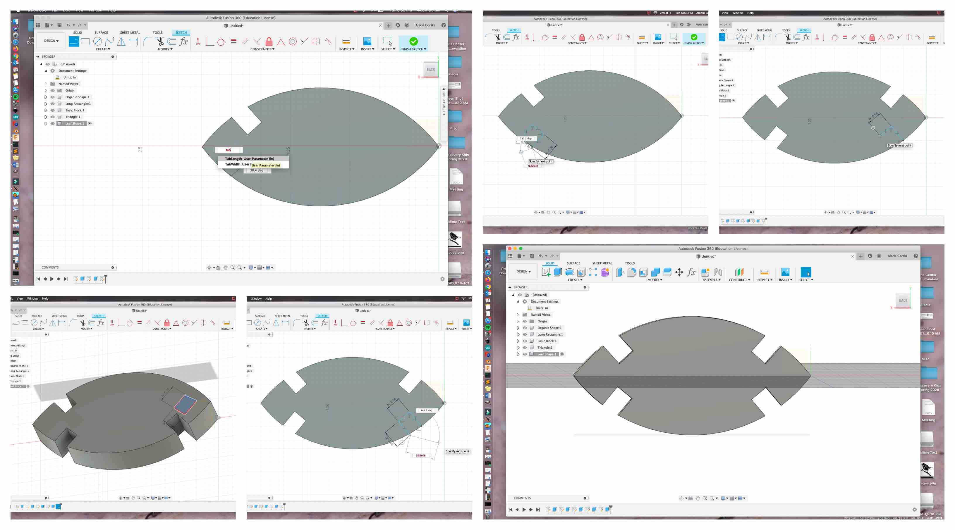
- I repeated these steps to produce the other three tabs at their selected locations. Once this was complete I finished modeling my first piece for my construction kit.
Long Rectangle
Using the same process as I did when creating the Leaf shape, I began to construct my next piece. I turned the eye off of the leaf shape and selected my long rectangle working tab. With this selected I created a sketch on the origin and began with a 2 point rectangle.
- This rectangle was then created to represent the sizes in my sketch, 5 inches long by .5 inches in height. I selected the face and extruded it to match the thickness of my material .16 inches.
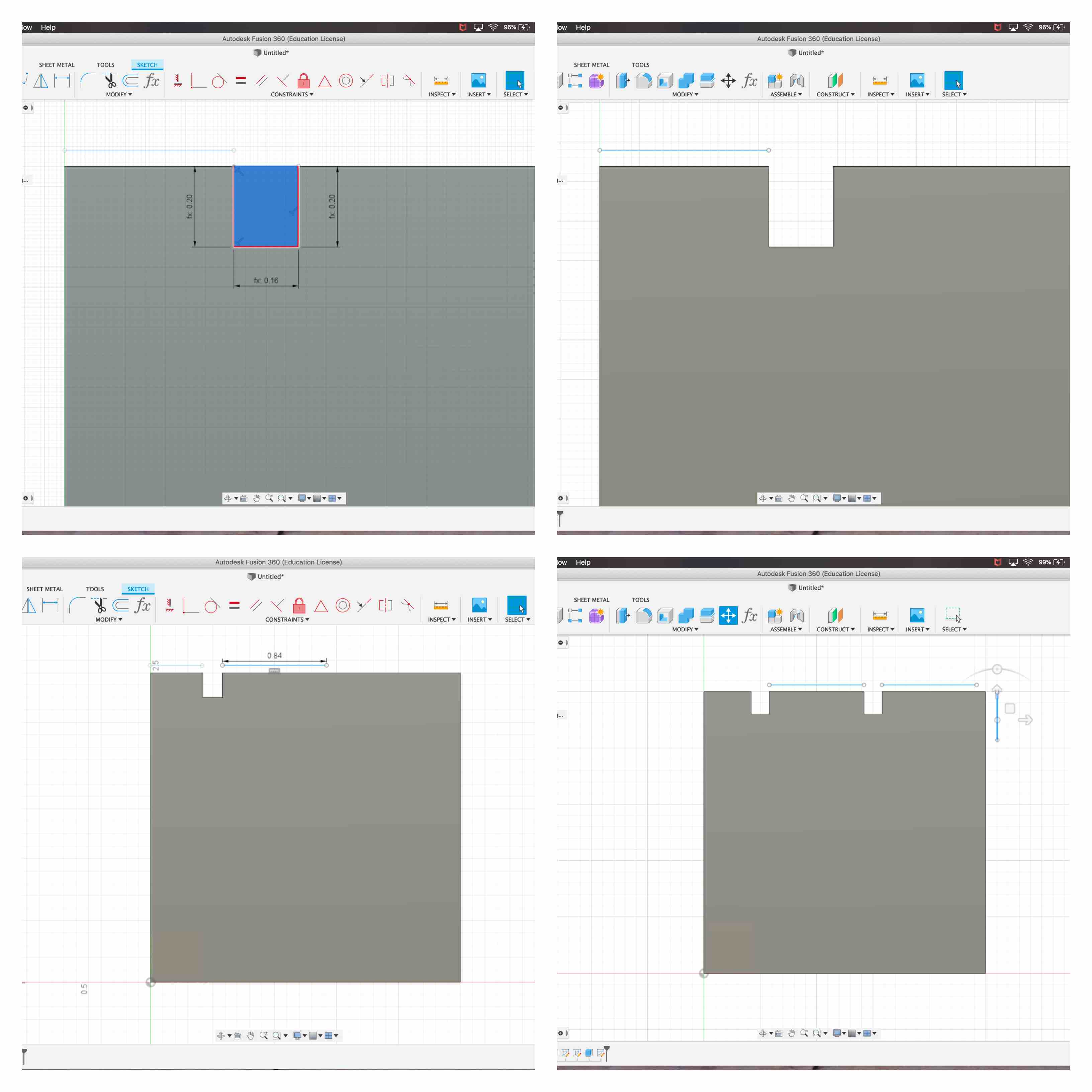
- In order to be sure I was following my math and designs for the tabs I created two rough lines the were an equal representation of the length between the edge and the first tab, and then represented the space between each tab that followed.
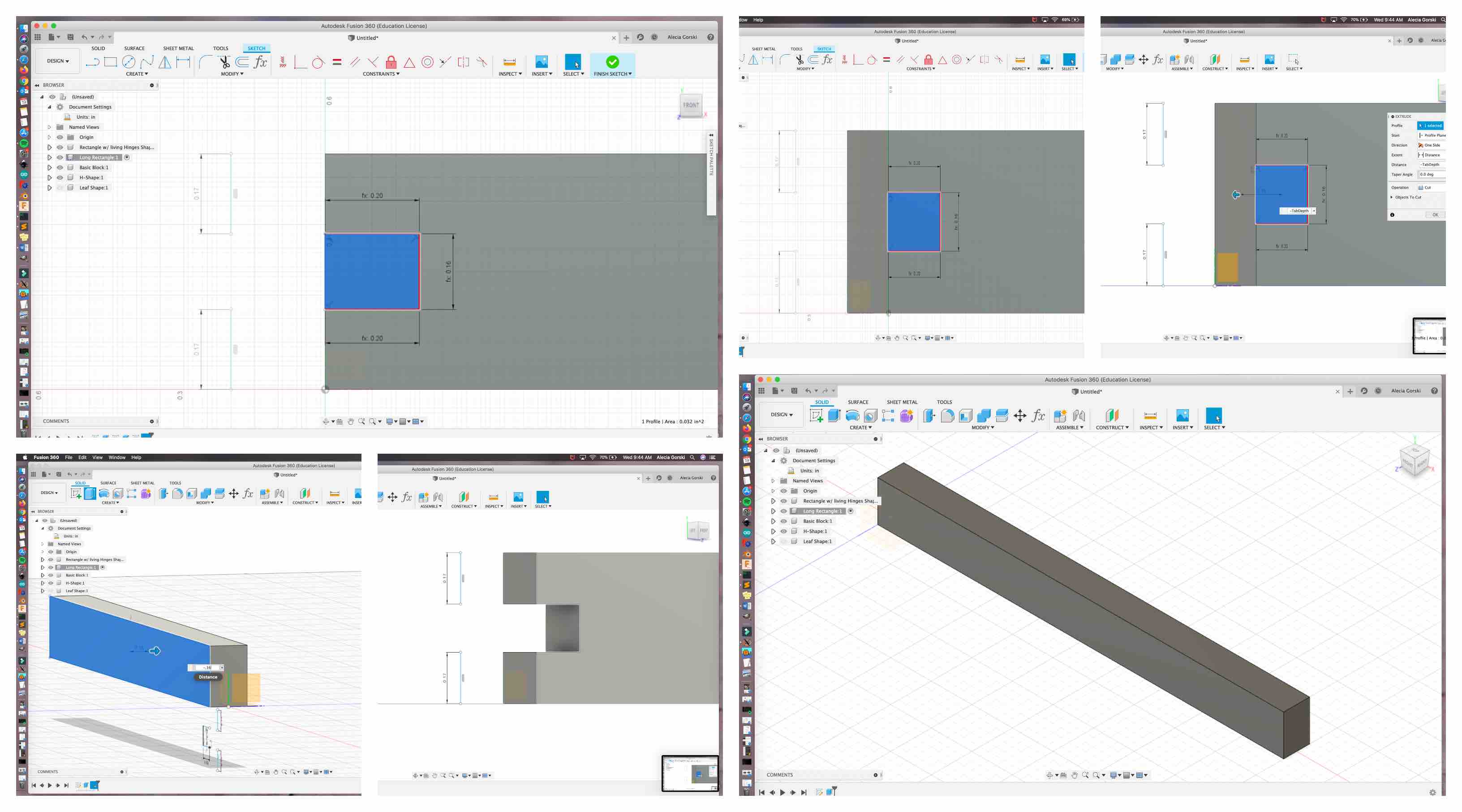
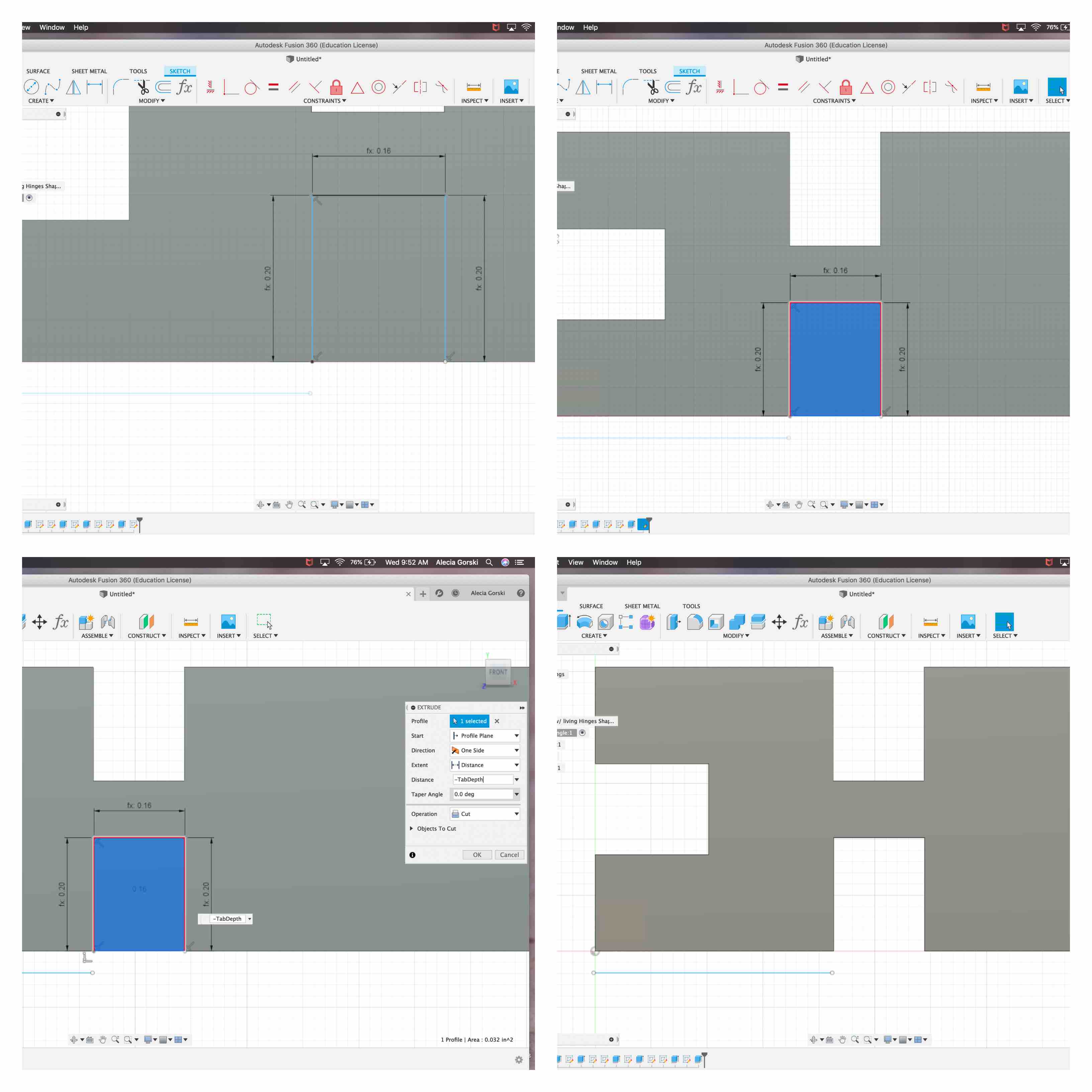
- When creating this piece I knew I wanted the tab to be centered on the .5 height. My two rough lines represented 0.17 inches between the edges and where I should place the sides of my tab. I began a sketch on the face of the rectangle. I selected the line tool and placed my first point on the edge 0.17 inches from the bottom. I then typed the length in at “TabLength” to keep my parametric design accurate. At a 90 degree angle I created another line and made it “Tabwidth”. My last line was created at a 90 degree angle from this and again set to represent the parametric “TabLength”. This created the face of my first tab on the rectangle.
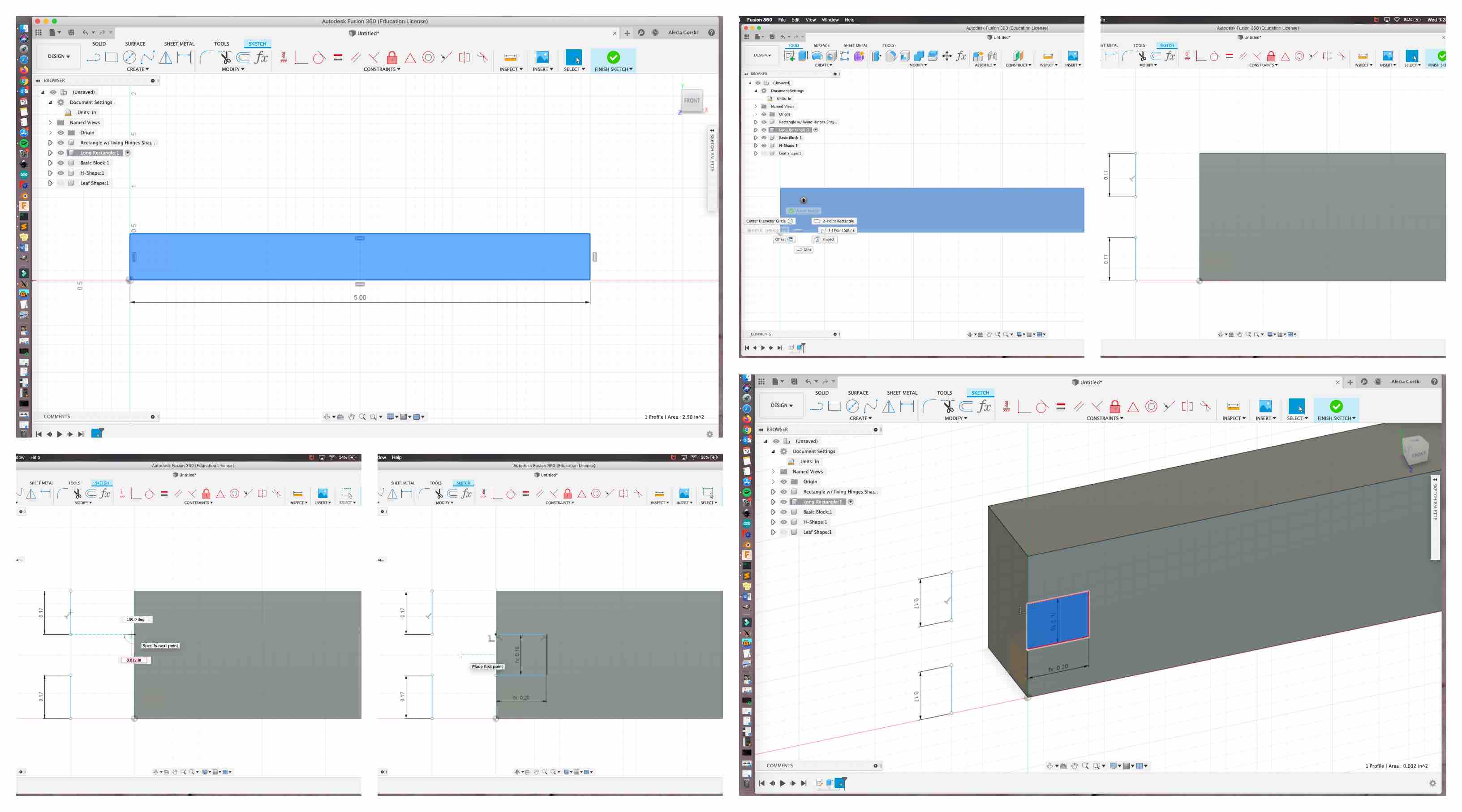
- With the face of my parametric tab selected I used my hot key Q to extrude it -“TabDepth”.
- I learned when extruding it is important to pay attention to whether you want to use a positive or a negative value. When entering the “TabDepth” for extruding I put a - sign in front of it to represent the pull through eliminating the space from the structure, not the push up function that would add that shape instead.
- I learned when extruding it is important to pay attention to whether you want to use a positive or a negative value. When entering the “TabDepth” for extruding I put a - sign in front of it to represent the pull through eliminating the space from the structure, not the push up function that would add that shape instead.
- This completed the creation of my first tab. I then moved on to the tab I placed on the opposite edge. I repeated the same steps on the right end of my rectangle. This completed my first two tabs, one on each end.
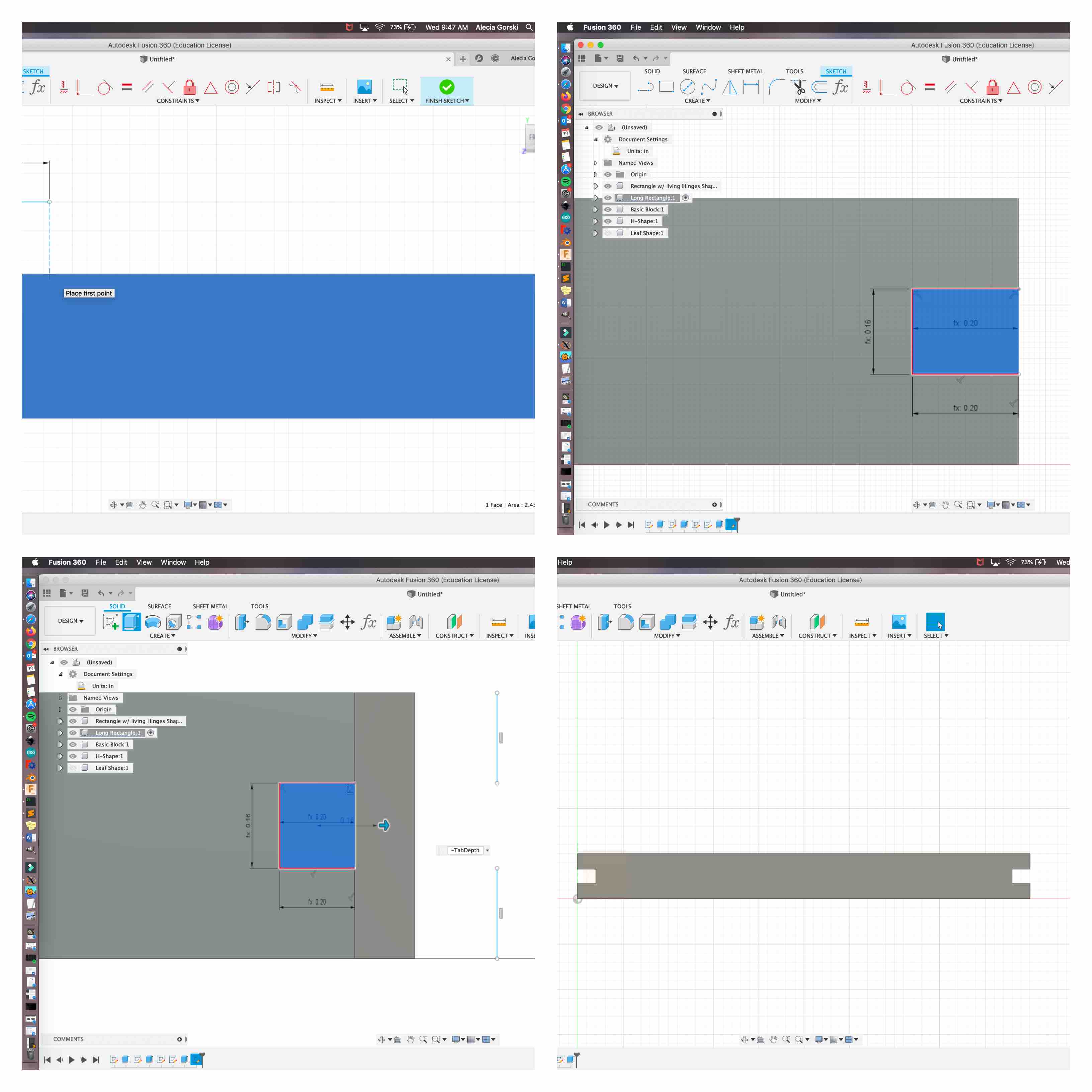
- I began my next step by creating the first tab along the top. I used the same process and parameters to make all the tabs the same. I used rough lines outside my shape to keep me dimensionally accurate and all my tabs representing the lengths I determined in my sketch.
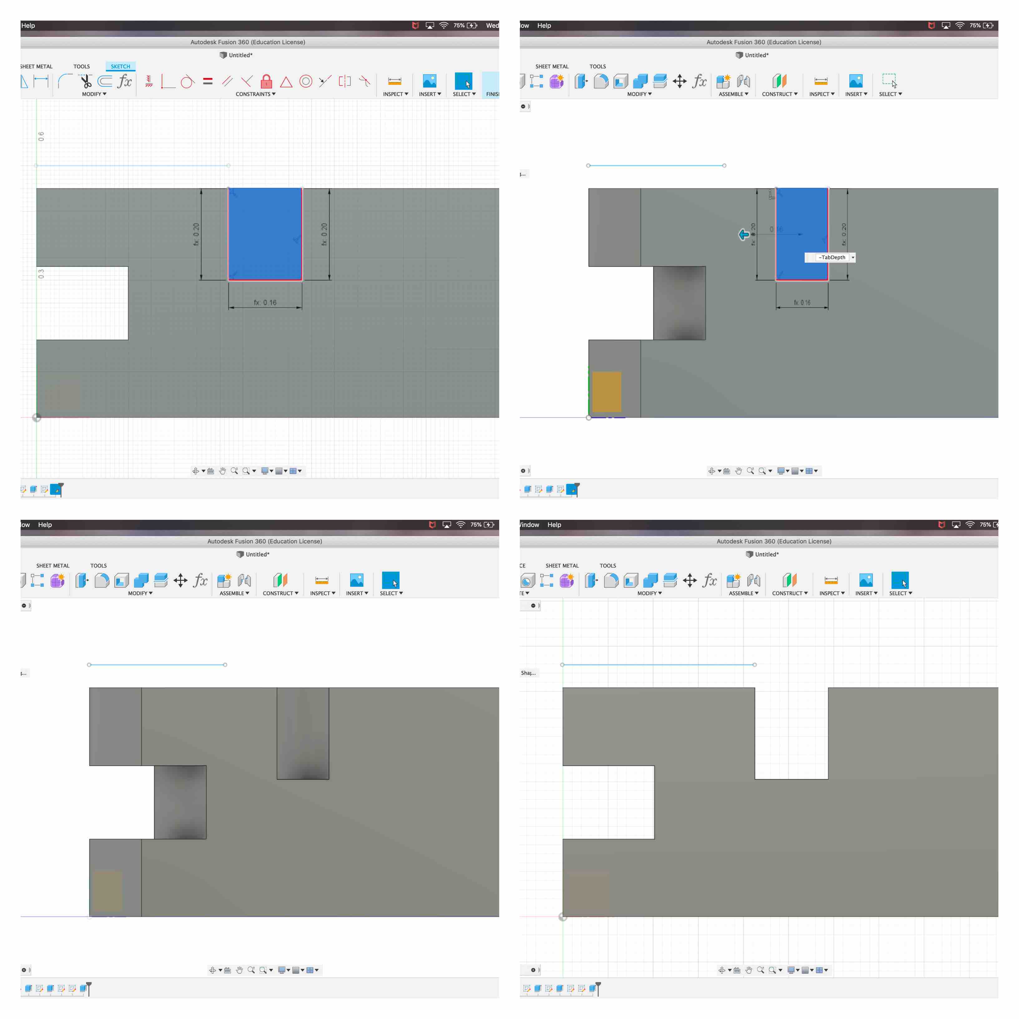
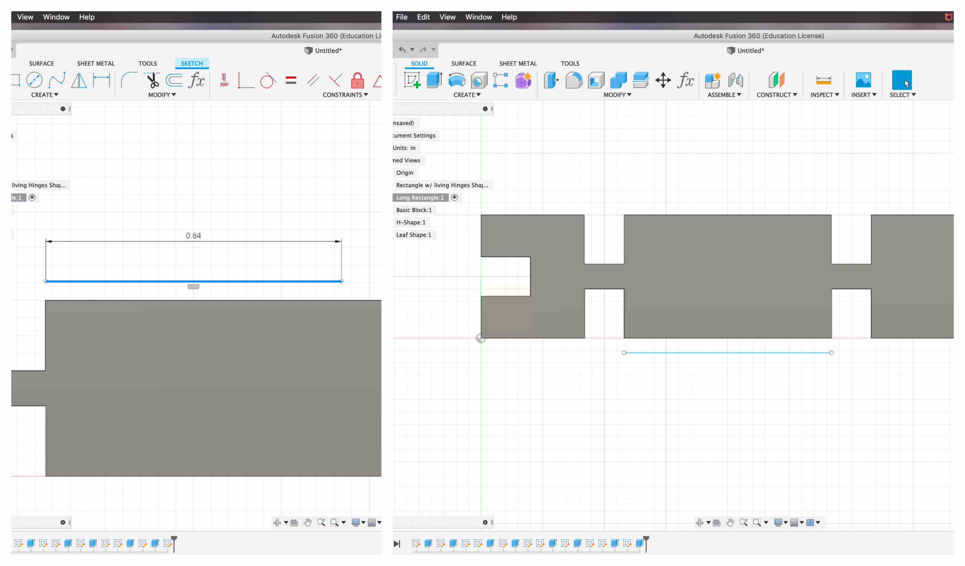
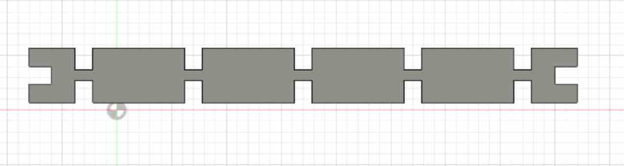
- I repeated this process to create all of the tabs along the top and the bottom. Being sure to place each tab .84 inches from each other I was able to place 5 tabs along the top and 5 tabs along the bottom as well.
Square
I wanted to create a combination of shapes that could go together in multiple ways. To do this I thought it would be best to do a mix of rigid shapes and organic. The next shape I created was the basic 2 inch by 2 inch square.
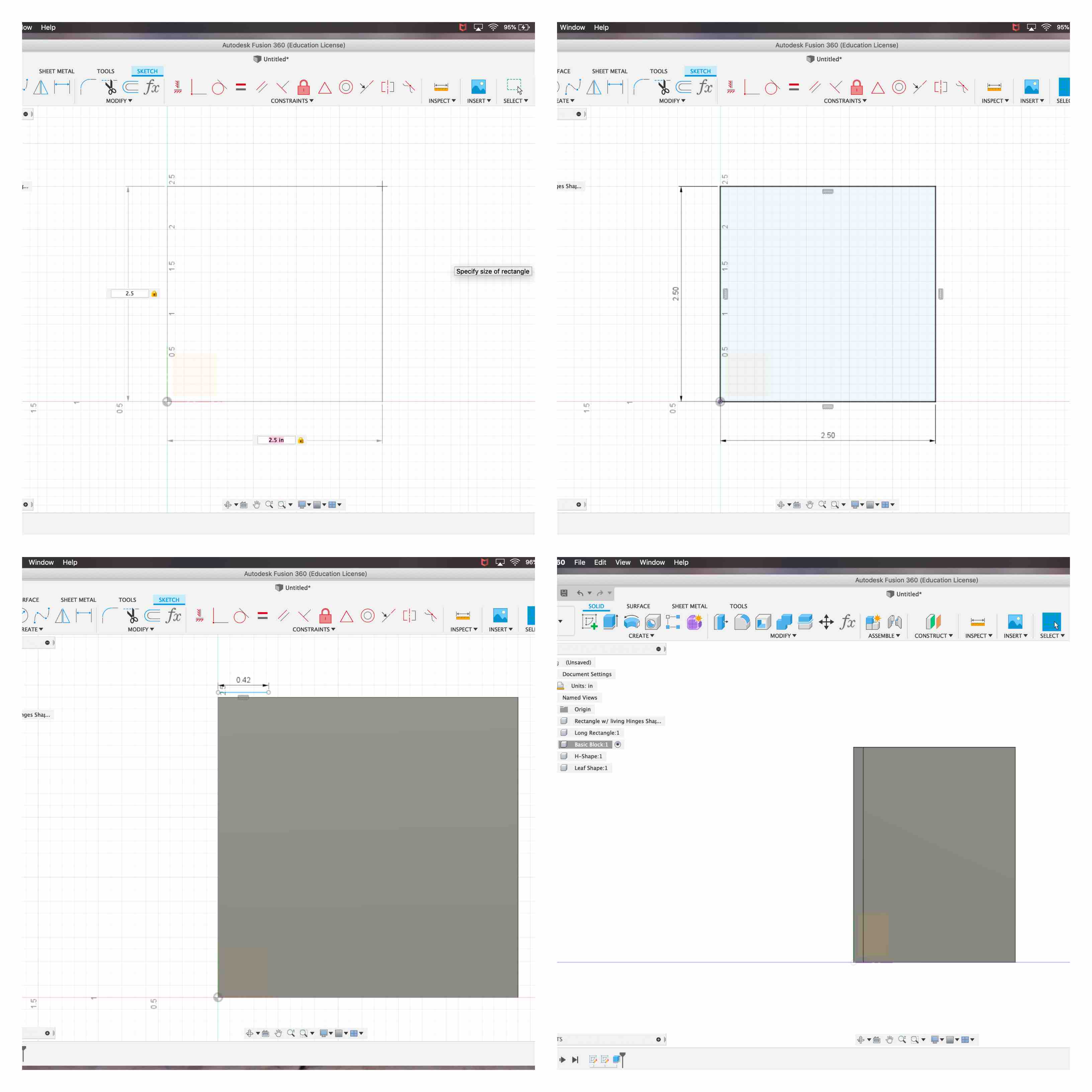
At this point I began to consider my design constraints. In other previously constructed pieces I used a measurement of 5 inches. In order to be cohesive and make sure the tabs line up with each other I decided to change my shape from 2 x 2 inches to 2.5 x 2.5 inches. This allowed it to be compatible with other parts.
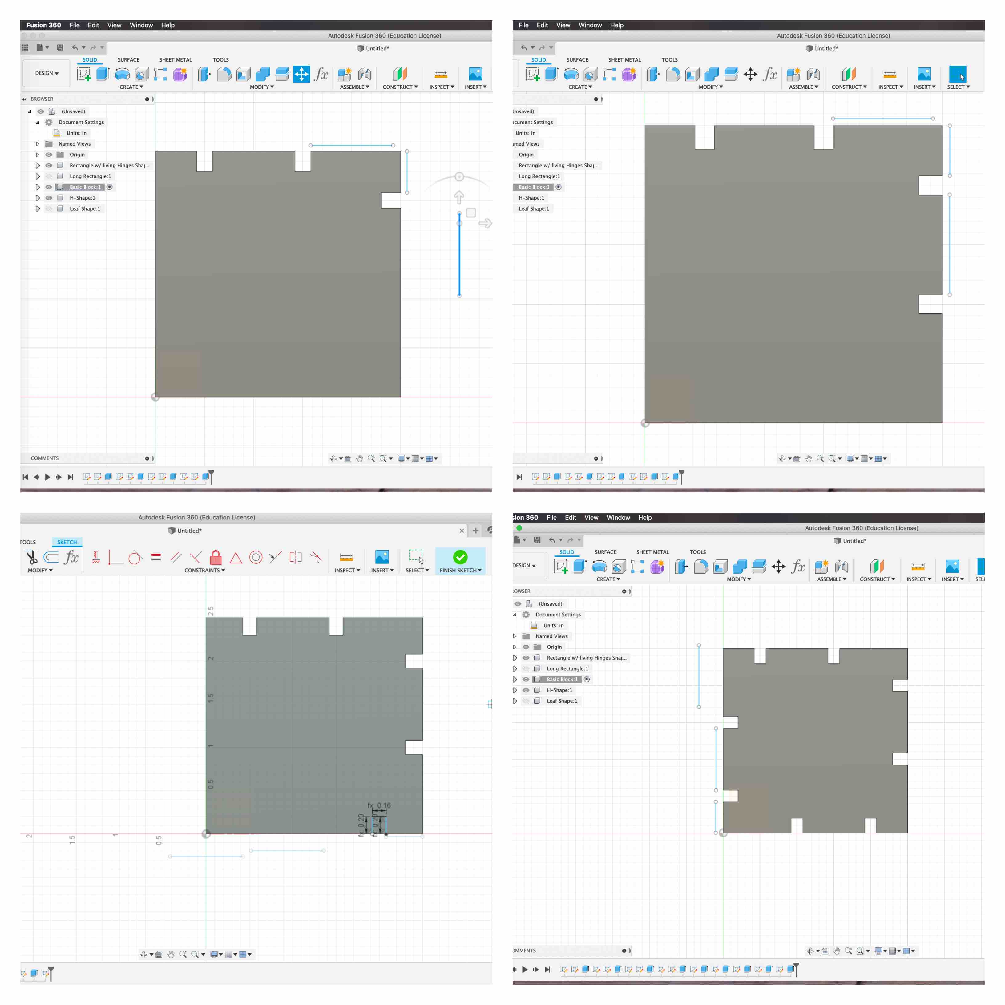
- My fist step was to turn off the view of my last two shapes created and turn on the view to my working screen on the square piece. I started a sketch on the origin plane and created a 2 point rectangle with 2.5 inches in length and 2.5 inches in height. I selected the face and extruded the shape to be .16 inches thick. This matches my material and other pieces designed. I now had my square the correct dimensions.
- I used the correlating measurements from my sketches and began to repeat the tab process around the square. Using the line tool I set the “TabLength” parameter for each of the lengths, as well as the “TabWidth” and “TabDepth” parameters to represent their respective measurements.
- I had just one difference to consider from the last piece I constructed. My tabs were equally spaced before but in my square there is left over room that offsets my tabs. I decided to design the square so that when rotated all side represent the same tab layout.
Big Rectangle with Living Hinges
I decided I wanted to incorporate living hinges into my project. In my sketches I made a long rectangle shape. I decided I could measure out room to create a space for a living hinge so that the larger rectangle could go from a rigid shape to one that could bend.
- When I began my layout I decided to turn off the other shapes so that they were not visible. I started a new sketch on the origin plane of my new component.
- I chose to use the 2 point rectangle tool. This shape allowed to me type in the exact dimensions I desired. I wanted to be sure this part was also dimensionally compatible with my other pieces, including space for the living hinge. I made this rectangle 2.5 inches by 5 inches. I went through the same extruding process and set it to represent the material thickness at .160 inches.
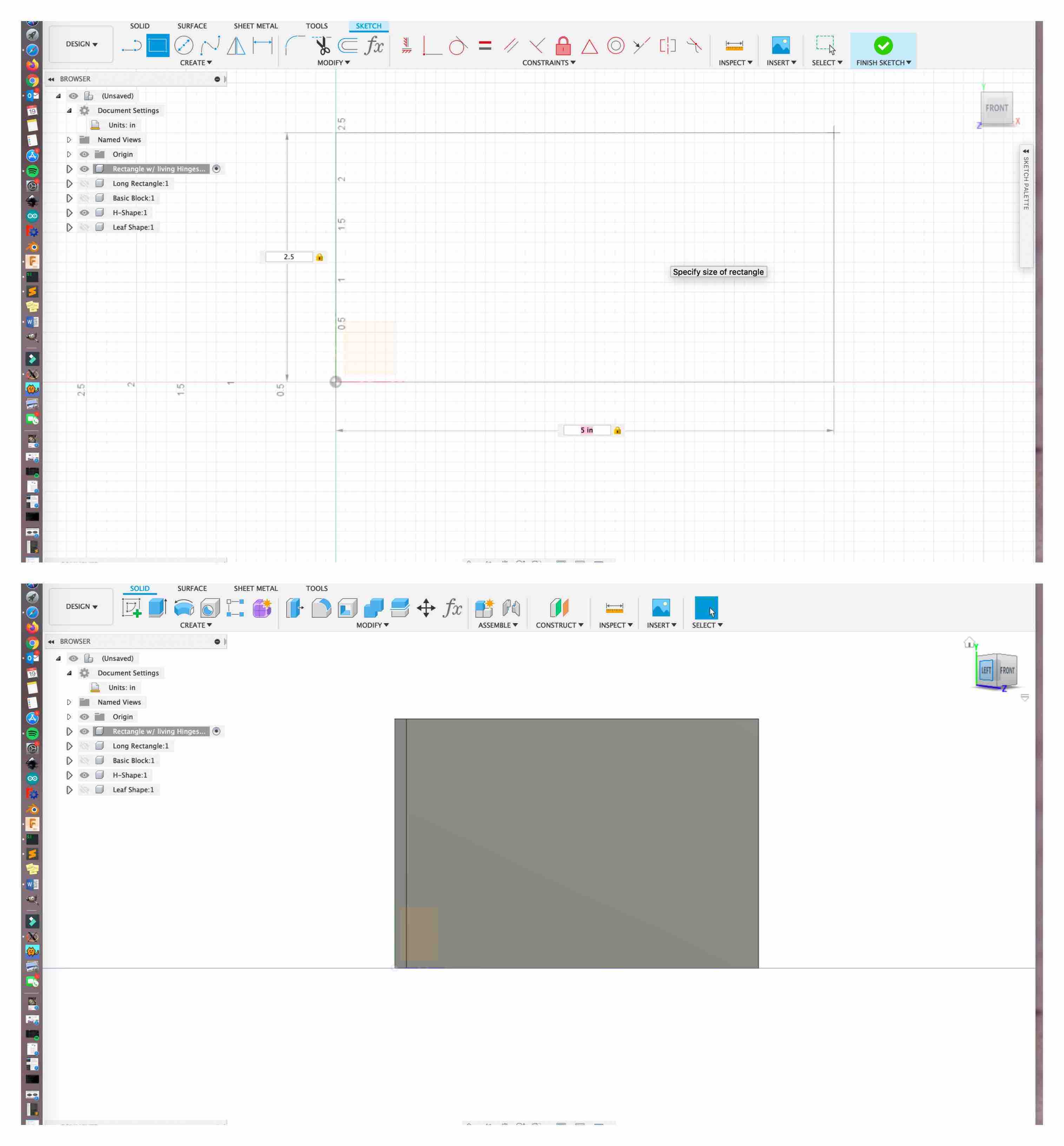
- Now that the base of my component is created I moved on to creating the tabs. The length is similar to the long thin rectangle I had already created. I used the basic tab layout but did not include the middle tab. The 1 inch by 2.5 inch space perfectly centered in the piece is for the living hinge to be added in the laser software.
- The tabs along the side resemble the same process I used for my other square that was 2.5 x 2.5 inches. I used the layout measurements to place my tabs in the hight portions of my rectangle. I again used the same Tab Parameters on this shape that I had with all of the previous pieces.
 This completed my larger rectangle with space included to add the living hinge.
Small Joint Square
This led me to the creation of my last piece. I was pleased with the previous shapes but I now needed to create one that could join all of my pieces in any order.
- I decided to create a small square that had the same tab parameters applied. I began by turning all other components off. I then chose to work on my small square component origin. I created a sketch on my plane and used the 2 point rectangle tool to make a piece that aligned with the rest of my kit. I made this 1 inch x 1 inch. I then used the hot key Q to extrude it the depth of my material.
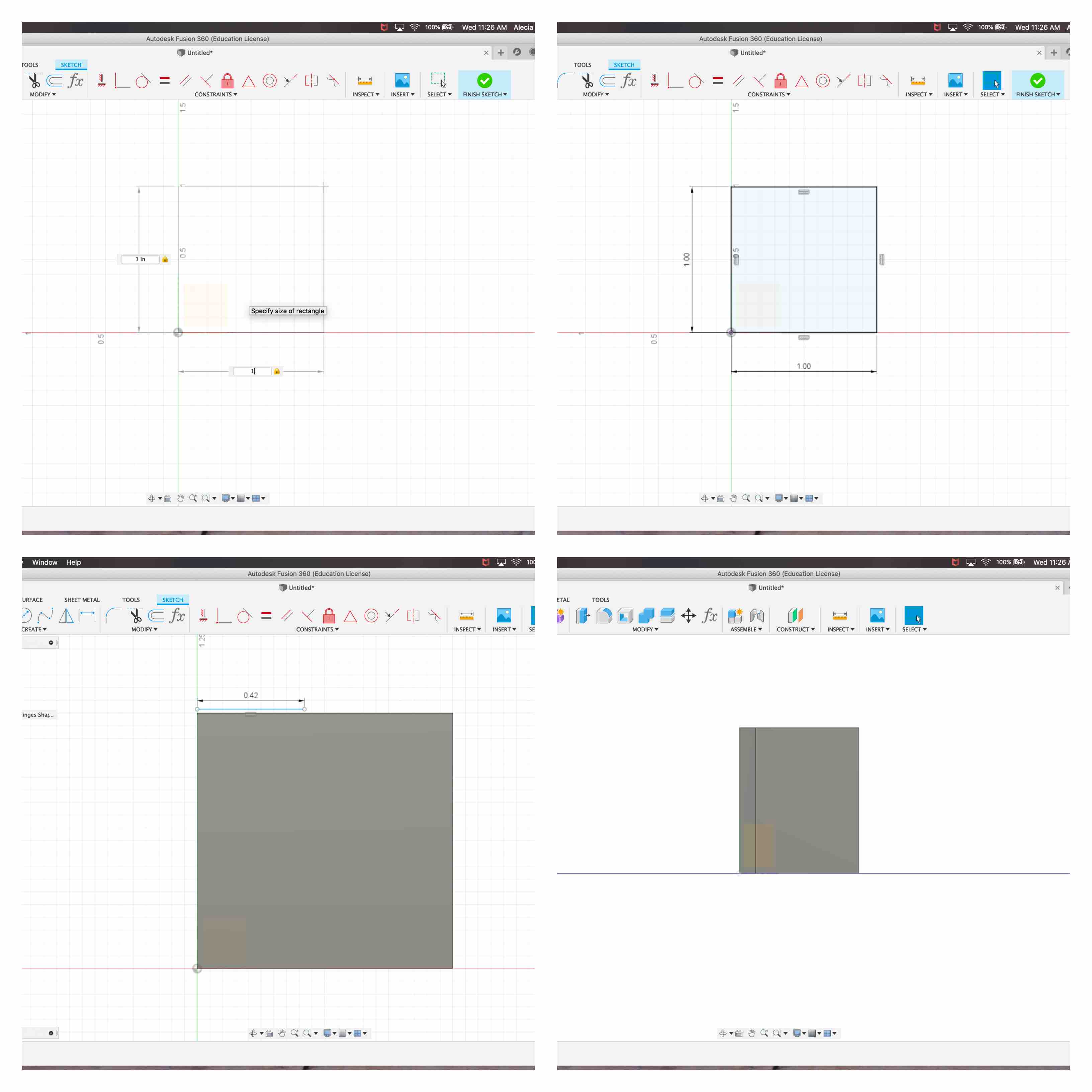
- I used the same tab process and parameters to create a tab on each side of the small square. This now allows me to connect a piece onto any side of my square. My pieces can come together to hold new forms now.
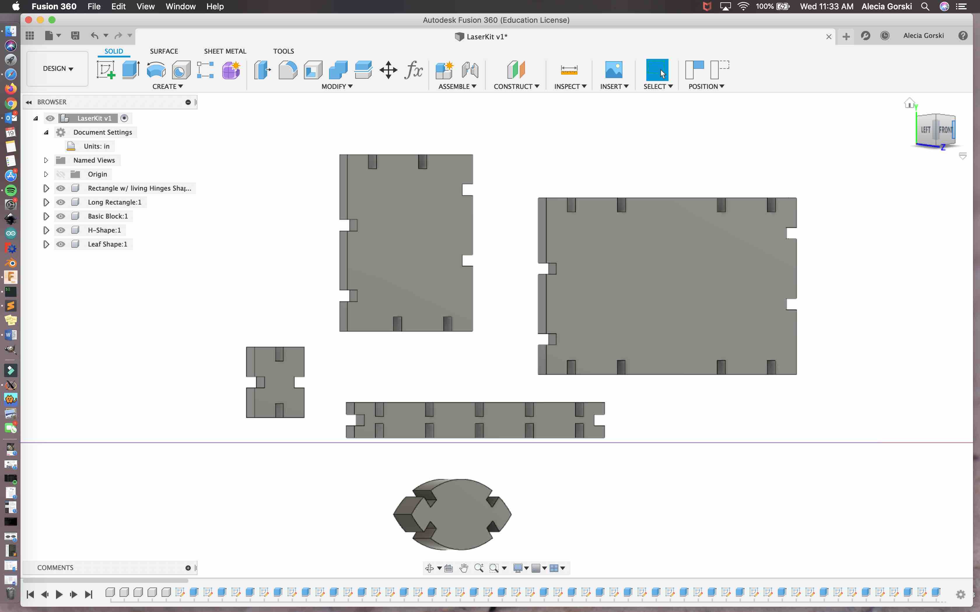
Modeling Overview
Overall when my pieces were finished they came together well. The tabs appeared to go together, line up well and resemble similar patterns. I had them all extruded to the correct width and I had a 3D model of all the pieces for my kit.
From Fusion 360 to CorelDraw
My next step was to convert my files to be compatible with CorelDraw. In my lab we use CorelDraw to communicate with our lasers. We have multiple lasers in multiple sizes. I chose to use the laser we named Matilda with a bed size equal to 18 inches x 24 inches.
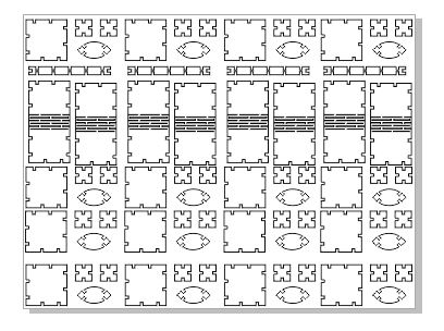
- My first step was to save each of my shape sketches separately as a .dxf files. This was done by right clicking on the last sketch completed for each shape and choosing to save as DXF. I put these onto a flash drive and I was able to import them to CorelDraw.
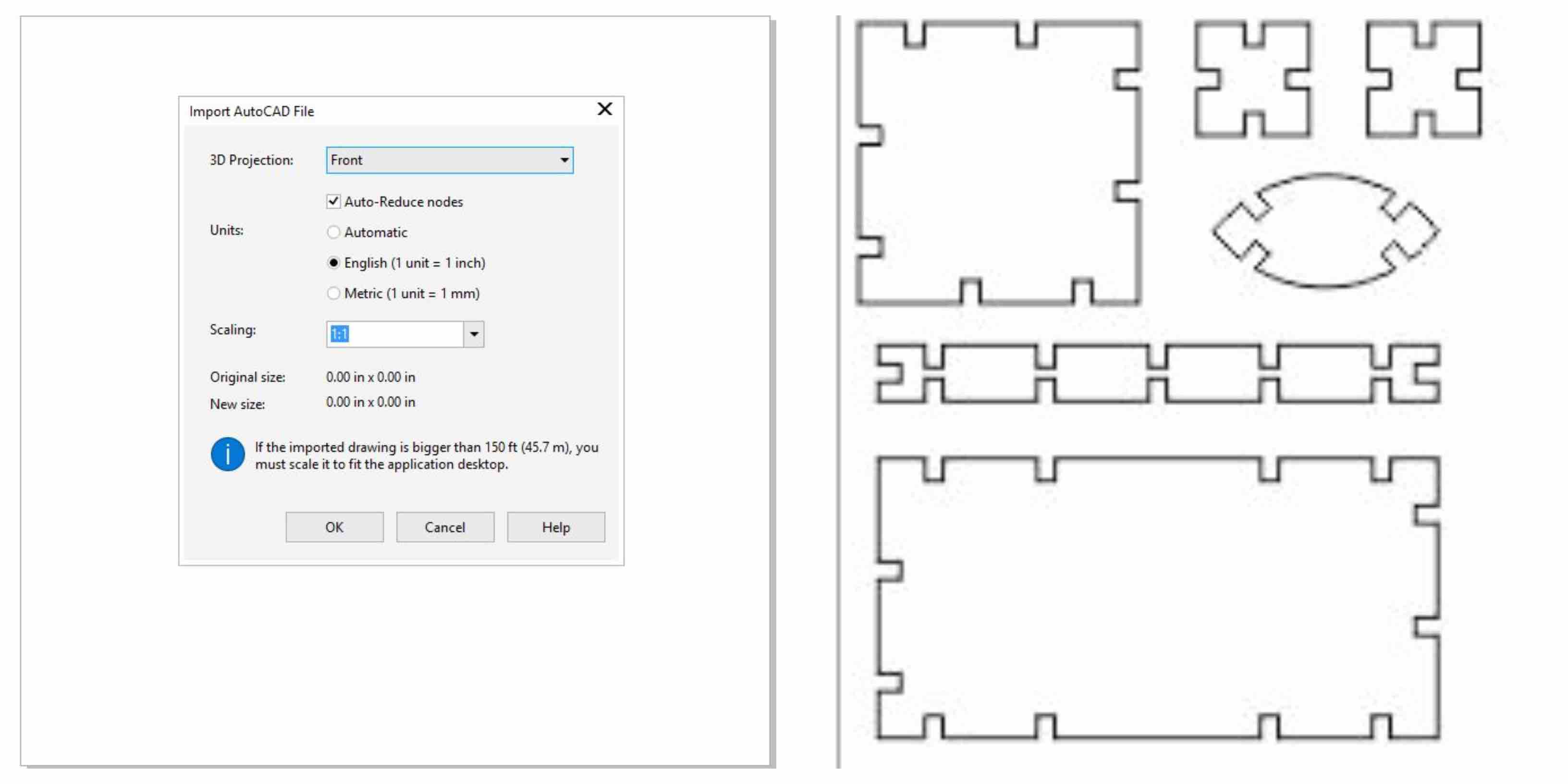
- There were two mistakes that caught me off guard in this step. Fusion 360 allows you to export the whole file as a DXF file. I thought this would be compatible. When in CorelDraw I chose to import AutoCAD File, and that was the other mistake. This was not the correct import method, and CorelDraw does not understand how to translate multiple sketches in the same DXF file. Once addressed these were no longer issues.
- There were two mistakes that caught me off guard in this step. Fusion 360 allows you to export the whole file as a DXF file. I thought this would be compatible. When in CorelDraw I chose to import AutoCAD File, and that was the other mistake. This was not the correct import method, and CorelDraw does not understand how to translate multiple sketches in the same DXF file. Once addressed these were no longer issues.
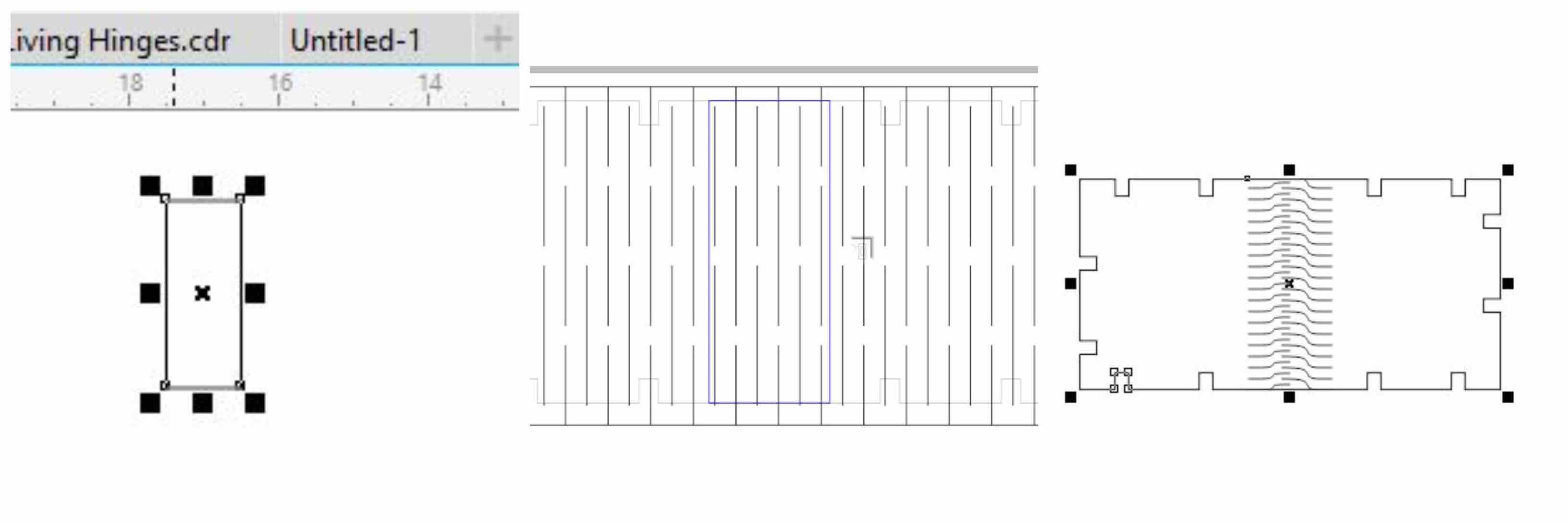
- Once I imported each .dxf file I collected them onto one page, careful not to adjust the sizes or scale. Once all my pieces were together I decided it would be best to add the living hinge. I made a simple box in CorelDraw with the shape tool. I then turned the stroke down to a hairline. I placed it centered in my Large rectangle. I then used it to power clip in a living hinge pattern. To do this, I selected my pattern. I then went to the top tool bar and went to Object. Under object there is a Power Clip option. I placed my pattern into my small rectangle frame I created earlier. This displayed my pattern over a blue box. I was then able to size my patter to fit however I wanted it to inside my frame now represented in blue. Once I was satisfied I accepted my placement and all the pattern outside the blue square was then ignored and disappeared (aka hidden by the program). I then used the stroke tool to turn off the stroke all together. This then turned my frame invisible.
- This is an important step. If you do not turn your power clip frame off then the laser will see it as a cut and want to cut the whole pattern. If it cuts the boarder frame then the whole hinge will be separated from the overall large rectangle.
- This is an important step. If you do not turn your power clip frame off then the laser will see it as a cut and want to cut the whole pattern. If it cuts the boarder frame then the whole hinge will be separated from the overall large rectangle.
- When my living hinge pattern was complete I was then able to nest all my pieces in place for a test cut. I always test the shapes first to see how well they cut, if they fit together and if they are truly representative of my concept. With all my pieces aligned in the top left of my document layout I was then able to move on to putting in my settings. I used the short cut command+p to print my document. A gray screen appears and I choose to use Epilog Matilda. When I click the preferences button located next to the name of the printer it opens the print driver. With the print driver I am able to communicate with the laser to tell it how strong, how fast, and how often to fire. This is where I control what I need the laser to do with the specific material I am using. If I were to put cardboard into the laser but use wood settings it would be too intense and possibly even catch fire. This is what we want to avoid. I decided to use a power of 26 a speed of 100 and a frequency of 5000. I turned it to vector cut only since I do not need the engraving options. I also changed my piece size to represent the material I had in the laser. I clicked okay in the blue screen to save my settings. I then clicked print in the gray setting screen.

- When I hit send my file then transfers to the laser. The laser then automatically adjusts the order in which it prints each piece.
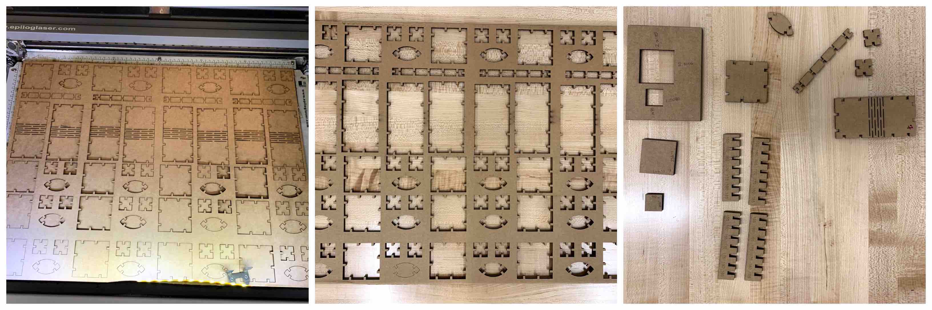
I had my 24 inch x 18 inch cardboard already loaded onto the bed of the laser. I used the triangle and the focus option on the screen of the laser to set my material at the correct focal length. I then hit reset to move my focus back to the top left corner of the laser (which I explain as the 0,0 point). With the air assist on and the ventilation pumping I started my laser job. I stood inside the yellow square to keep an eye on the laser.
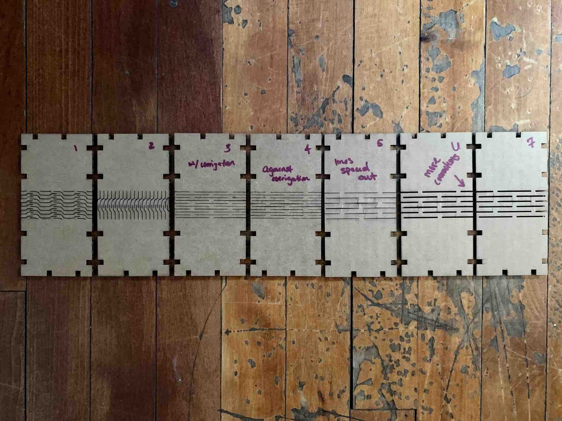
There were a few complication I faced at this point. The first being the design of my living hinge. I went through 7 different iterations before I found one to settle on.
- My first test was with a wave hinge pattern. This didn’t seem to work super well. It didn’t bend much.
- I changed the direction the design was going in the power clip. This adjusted how it was printed in relation to the direction of the corrugation. That still didn’t do much to improve my hinge, however it was now even harder to bend.
- I decided to change my hinge pattern to straight lines instead. These lines went along the corrugation of the cardboard. This was better but came apart too much when bent.
- I now used the same pattern but ran it against the corrugation. It worked better but I wanted to do more.
- I spaced out the lines and cut iteration 5. This worked again but wasn’t exactly what I was going for.
- The sixth time I cut this piece was to add more space into each cut. I took the lines, added a 2.0 point stroke and then bitmaped. I took the bitmap and converted it back to a vector with quick trace. This allowed me to make each line more of a rectangle, therefore removing more space. This was my best result yet.
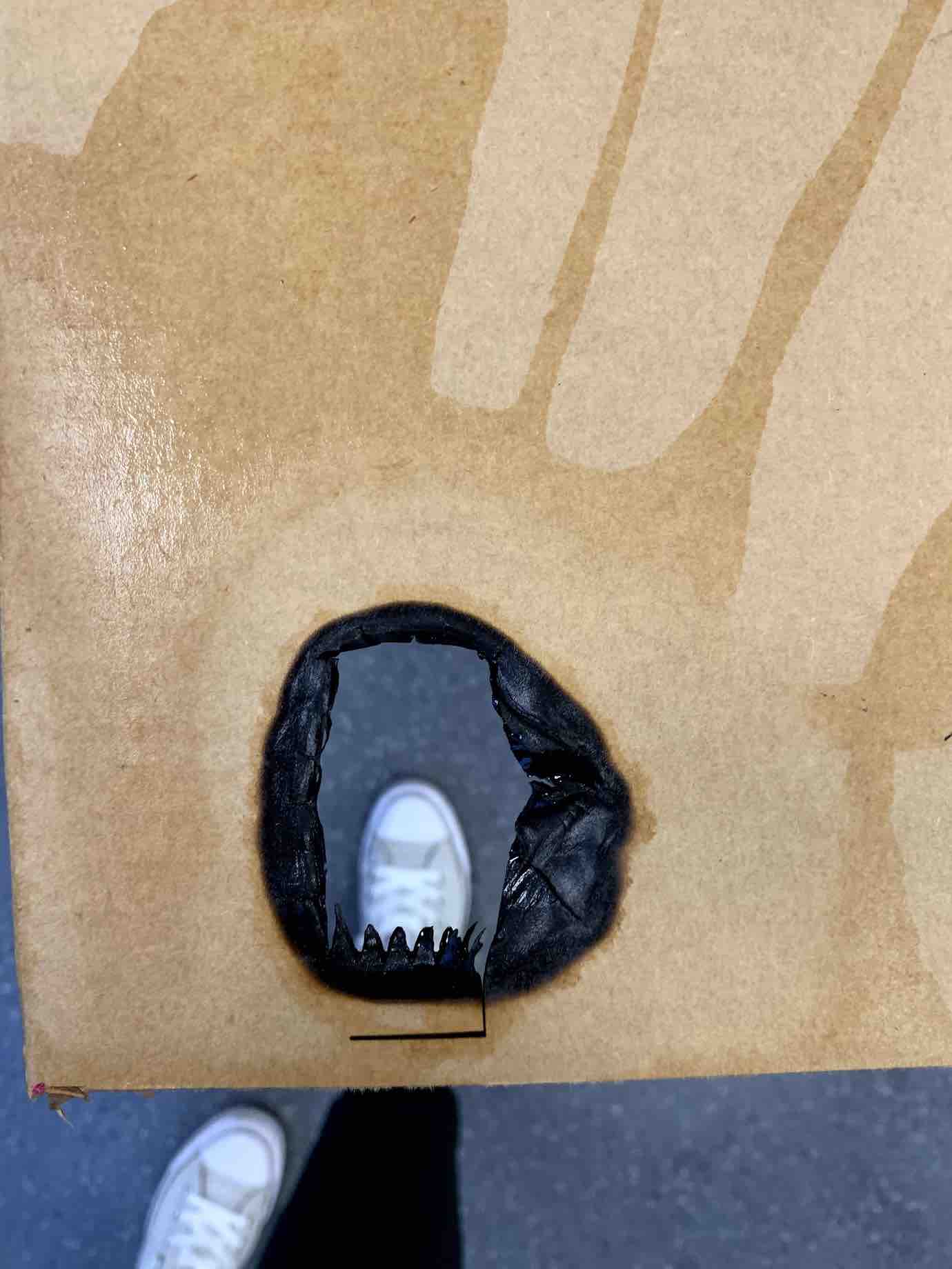
- With the time I had left I decided to try one more hinge style. This was a living hinge called diamonds. This was the fatal mistake of the day. While standing by the laser determining if this cut would work or not I experienced my first ever laser fire. Working with this equipment since 2014 and never having started a fire I was very shocked. I lifted the lid and stopped the laser and attempted to blow the small beginning flame out. This however fueled the fire. In the mean time one of the local instructors came to help and a lab technician brought water to dowse out the flames that were now growing bigger. In the end there was no harm done to anything other than the cardboard and my fire free record. I learned a lot from pushing the limitations of the machine and how careful you must be with not just cardboard but all materials.
- Once satisfied with my cut outs and satisfied that the laser was okay I decided to layout my pieces to fit a sheet of 24 x 18 cardboard and prepare it to cut my final construction kit.
- I made sure that all my lines were hairlines so that the laser would recognize to cut them all. I turned the raster engraving settings off. I double checked the rest of my settings and I sent my file to the laser.
Laser Cutter in action - From Youtube
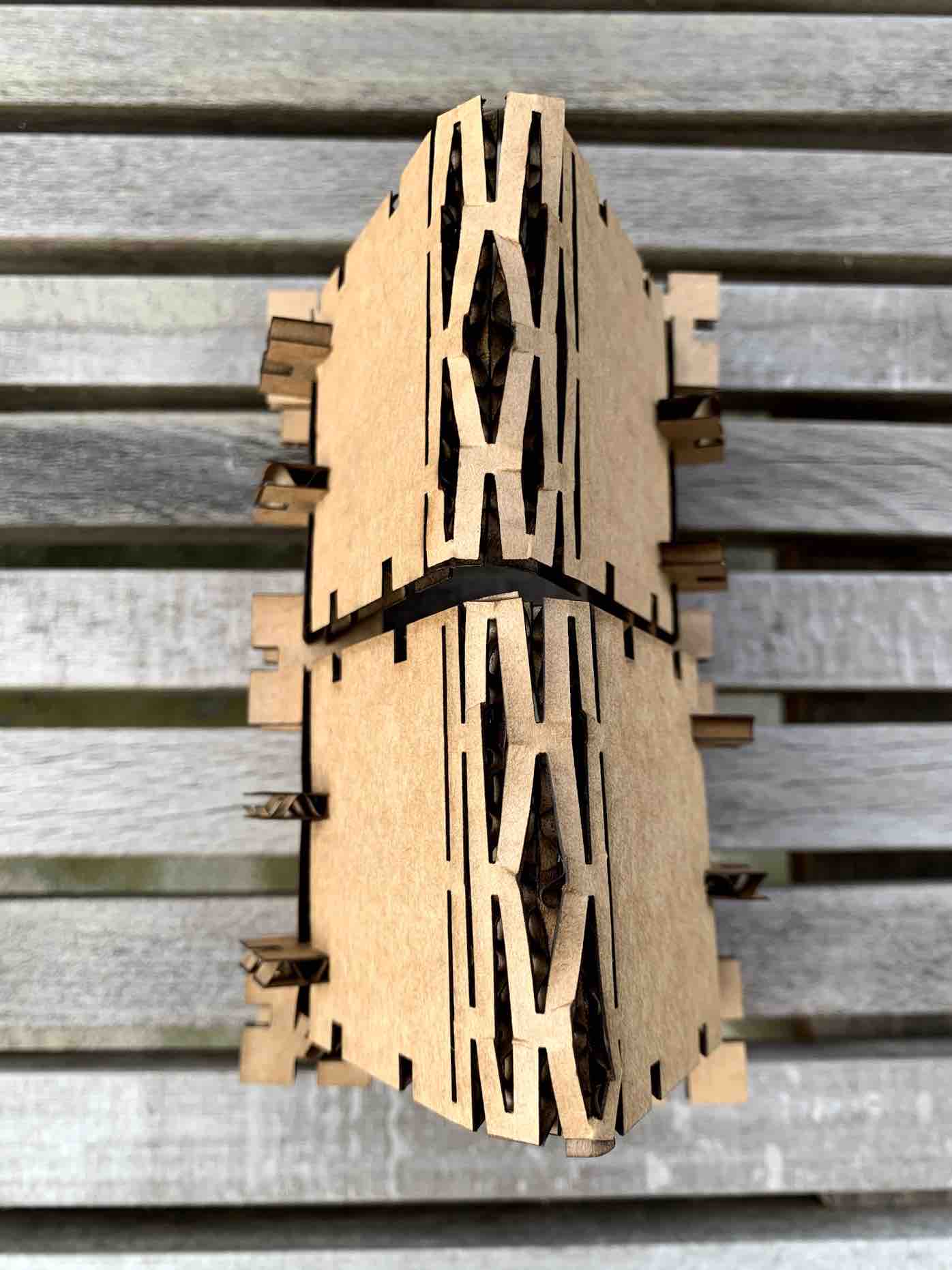
Construction Kit Hero Shots
With all my pieces cut I gathered them into a small box I upcycled from a separate project at work. I was able to assemble the pieces into at least 4 separate constructions. I built a house using the long rectangle with the living hinges to bend as a roof. I built a small garden fence with two trees, one on each corner. I built a bush to be placed in the garden, and I built a picnic table representation. Overall I was pleased with how my project came together.
I first built the cabin to make use of the living hinges. I then built the picnic table that sits outside the cabin. I took the concept from the picnic table and created the bush that sits inside the garden. The garden has two trees on opposite corners.
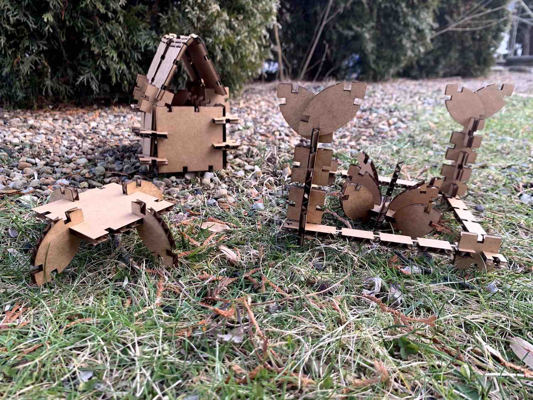
The parts in my kit can go together in many different ways.
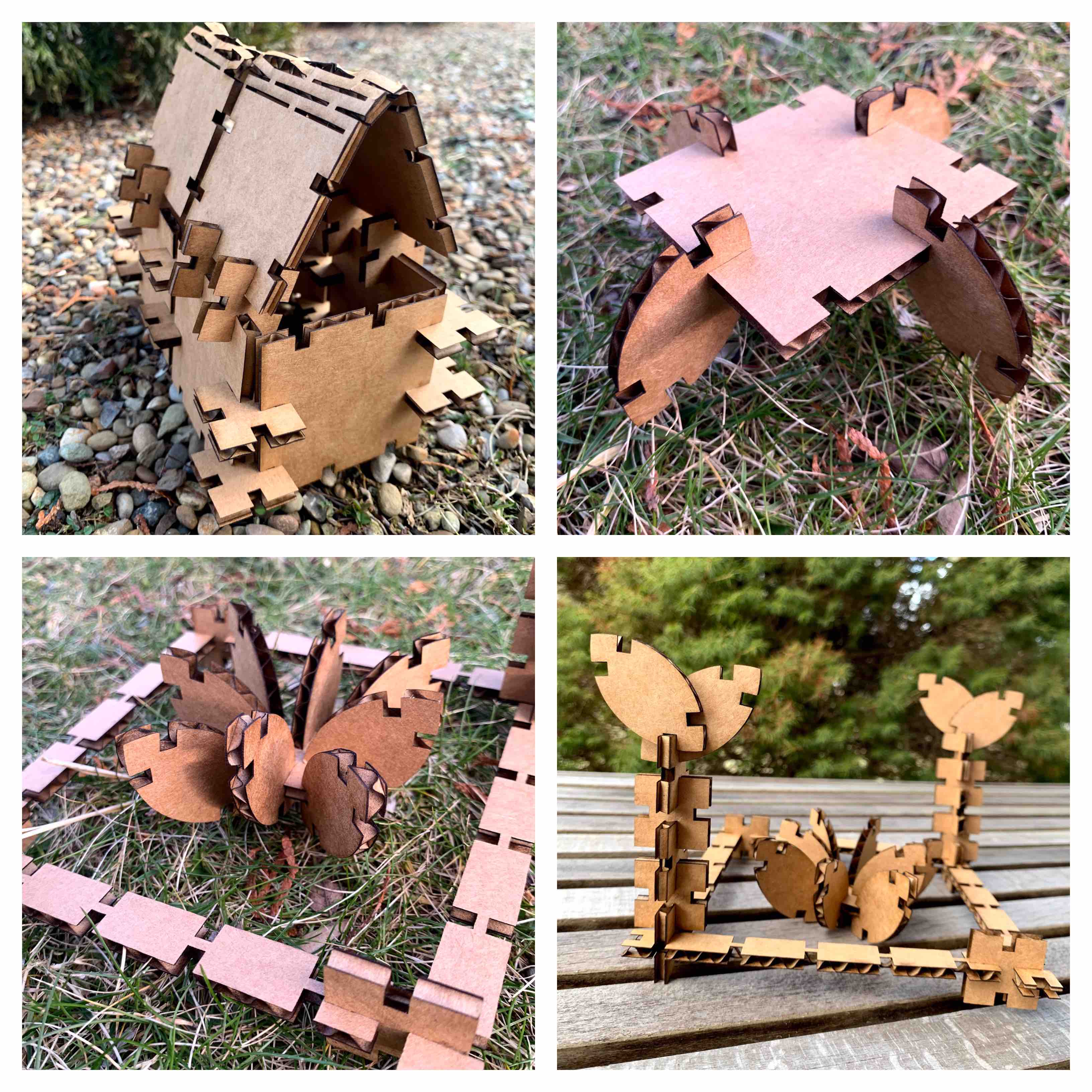
I also worked to get living hinges in the corrugated cardboard.
Parametric Demonstration
I wanted to be sure that I demonstrated parametric changes to my file. When I completed my construction kit I went back into my Fusion 360 File. I changed some tabs to show simple parametric changes. I made a change to the thickness of one of my pieces and represented how the parametric values would then be used.
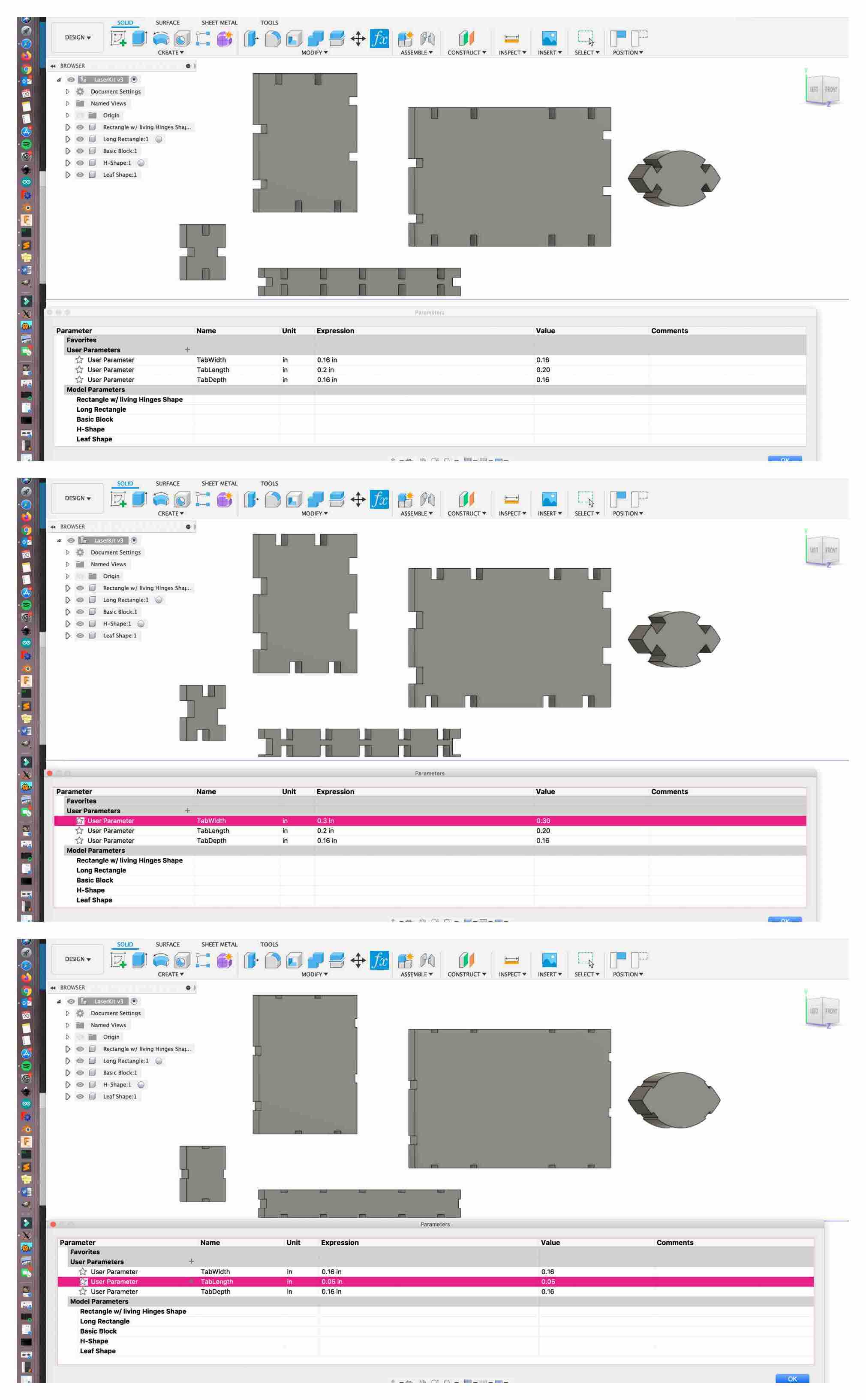
- The first image in the above collage shows my original tab parameters. It then lists all the components that use these parameters.
- The second image is an example of when I change one of those parameters (TabWidth) from .16 inches to .30 inches. The illustration then shows the difference and displays all the tabs changing together.
- The third image shows a change to yet another parameter (TabLength). This was changed from .2 inches to .05 inches. There is a more drastic change in the tabs and you can see it has been applied uniformly throughout the pieces.
My next challenge was to demonstrate the depth parameter. I changed the depth of one of my squares to reflect a much thicker material.
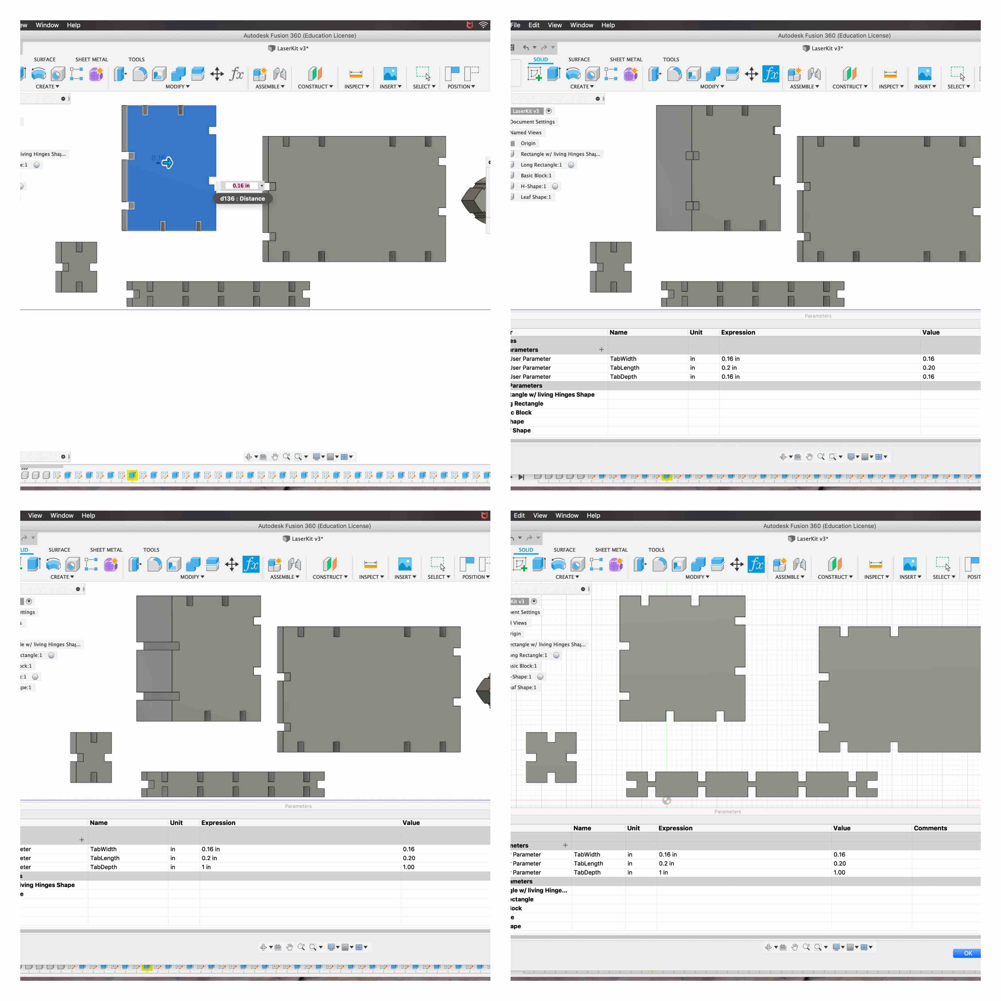
- You can see in the illustration about that the selected piece is blue. This means I can make changes to the face.
- I extruded it to represent a thicker material. You can see the tab does not go all the way through the material any longer.
- I opened my parameters option in my Modify Toolkit and made an adjustment to the “TabDepth”. I change the amount to 1 inch to represent the material thickness and you can see the tab now goes all the way through with all tabs. If I had changed all the shapes to 1 inch depth it would have represented the same change all the way across each piece.
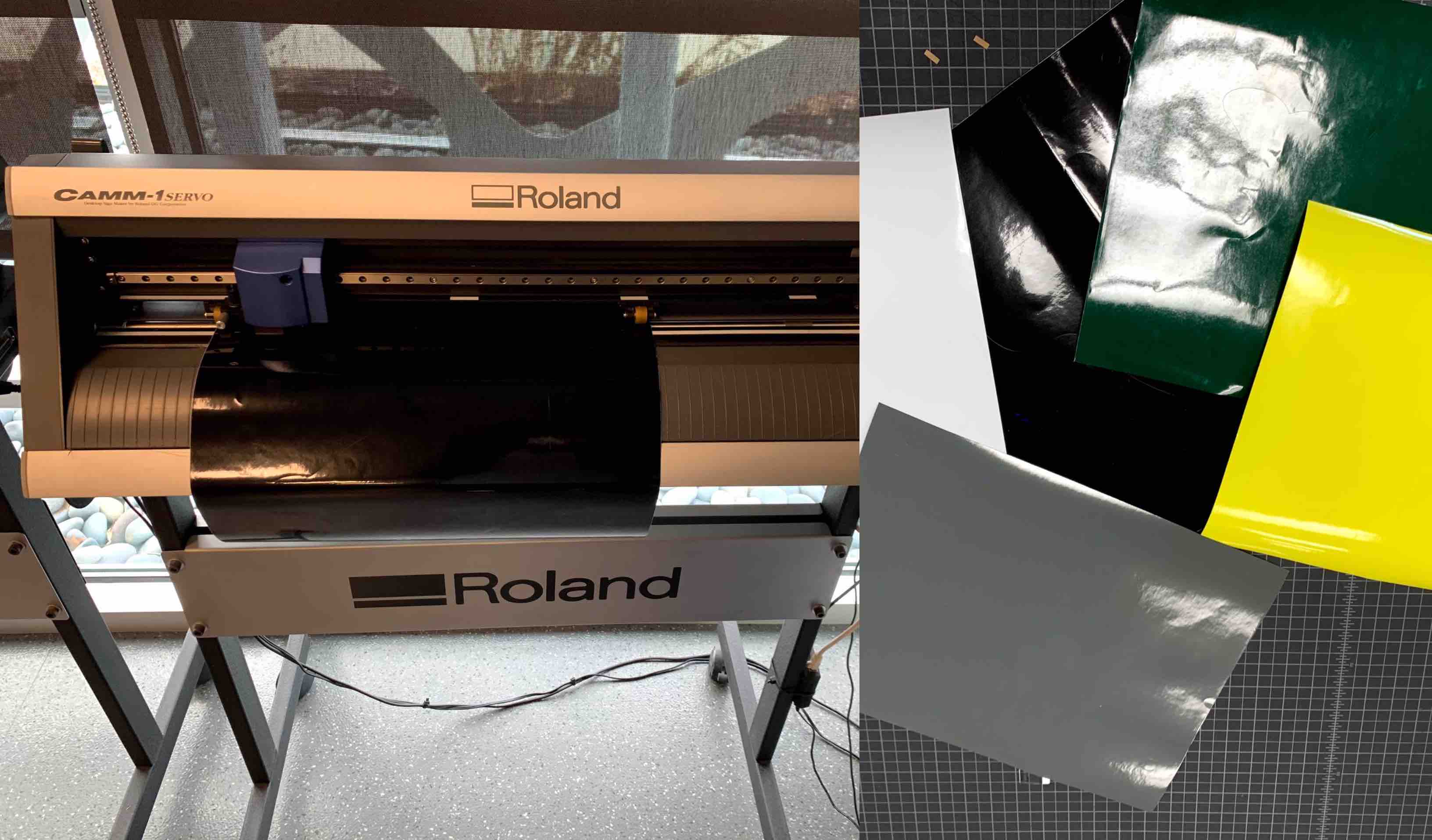
Vinyl Cutter
In our lab we use a Roland Vinyl Cutter. Vinyl is a shiny material that resembles a thin application of plastic. It has a sticky back and can be removed from its backing to adhere to many different surfaces. Our challenge this week was to get familiar with the process of using the vinyl cutter by creating anything with it.
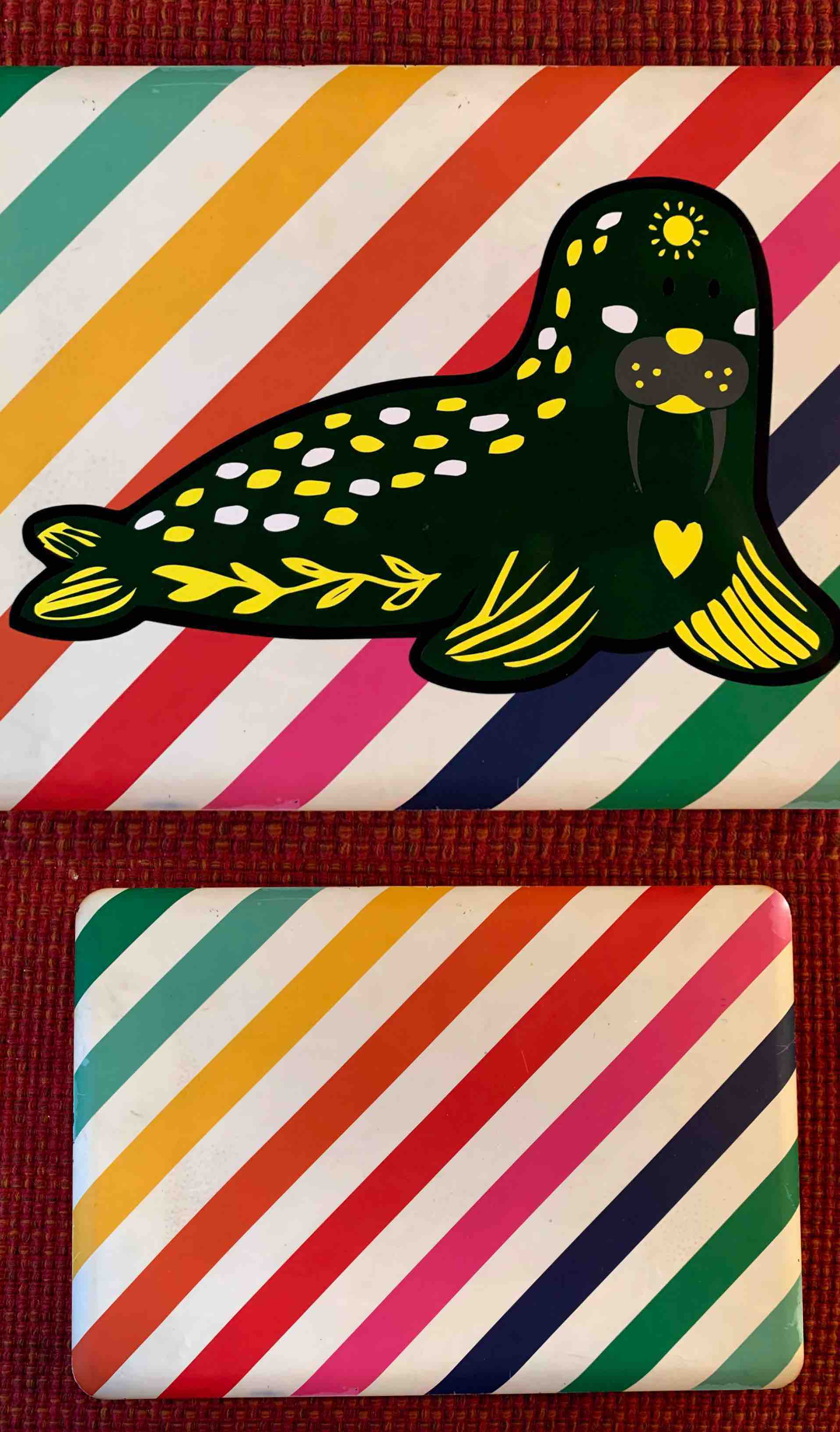
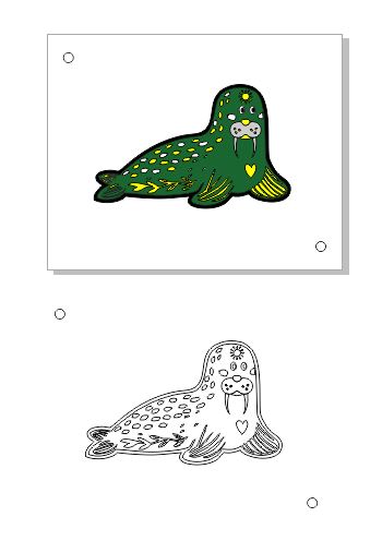
Anything, being a very broad focus, I decided to create a walrus. I wanted to utilize multiple color layers.
Design Stage
- My first step was to create my design file in CorelDraw. There are many different programs you can use to communicate with the vinyl cutter such as CorelDraw or Cut Studio. Although Cut Studio has its advantages I prefer to use CorelDraw so I can stay consistent with designs I might want to use cross media with the Laser Cutter.
- I based my walrus off of a design I had previously seen. I created my walrus figure. I then took the outline and contoured it outward. This allowed me to accommodate a sold background for my layers to start on. I chose to make that black. I also added two circles to opposite corners of my design. This was for registration use (explained in later steps).
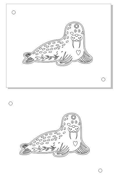
- I then began putting in the details to the walrus. Knowing I wanted to use multiple colors I began filling the different shapes with the color vinyl I would use.
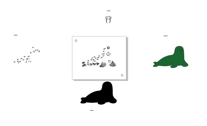
- When I had a final color design made up I then grouped each piece together by color. When grouping objects you can select them all across your document and when you group they stay in relation to each other.
- This allowed me to stay registered per color and to separate each one from the rest easier. When each color was separated and grouped together I turned the fill off and made each of my lines a hairline. This is important so that the vinyl cutter knows to cut just the single lines.
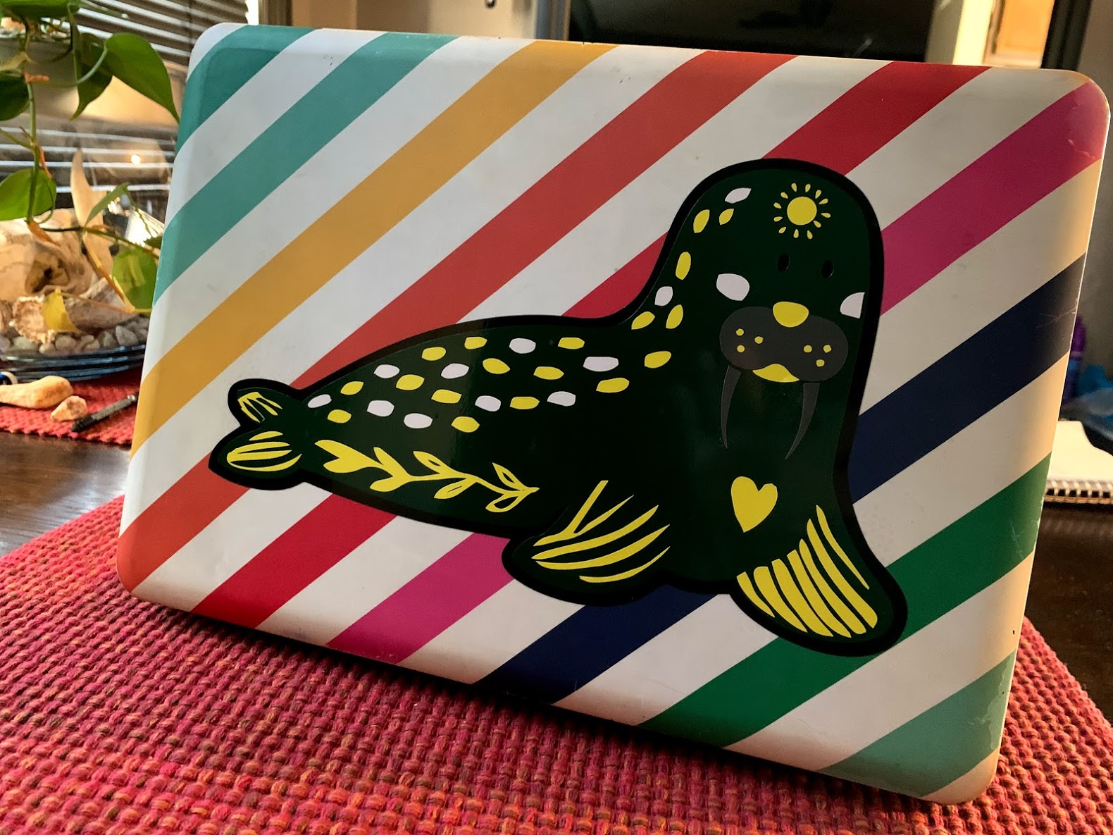
- Once my design is ready to send through I can cut my vinyl pieces. I chose to do a laptop decal so I made him larger. I used sheets 12 inches x 15 inches.
Vinyl Cutting with our Roland
Once all the colors are cut out to fit the design you can begin the process of using the vinyl cutter. There are a few steps that you will be required to move between the computer and the vinyl cutter itself.
- With your first color of vinyl selected and your sheet in hand, place the first layer design into the file document area.
(Be sure that anything you DO NOT want printed is moved off of the document area. Otherwise it would also cut.)
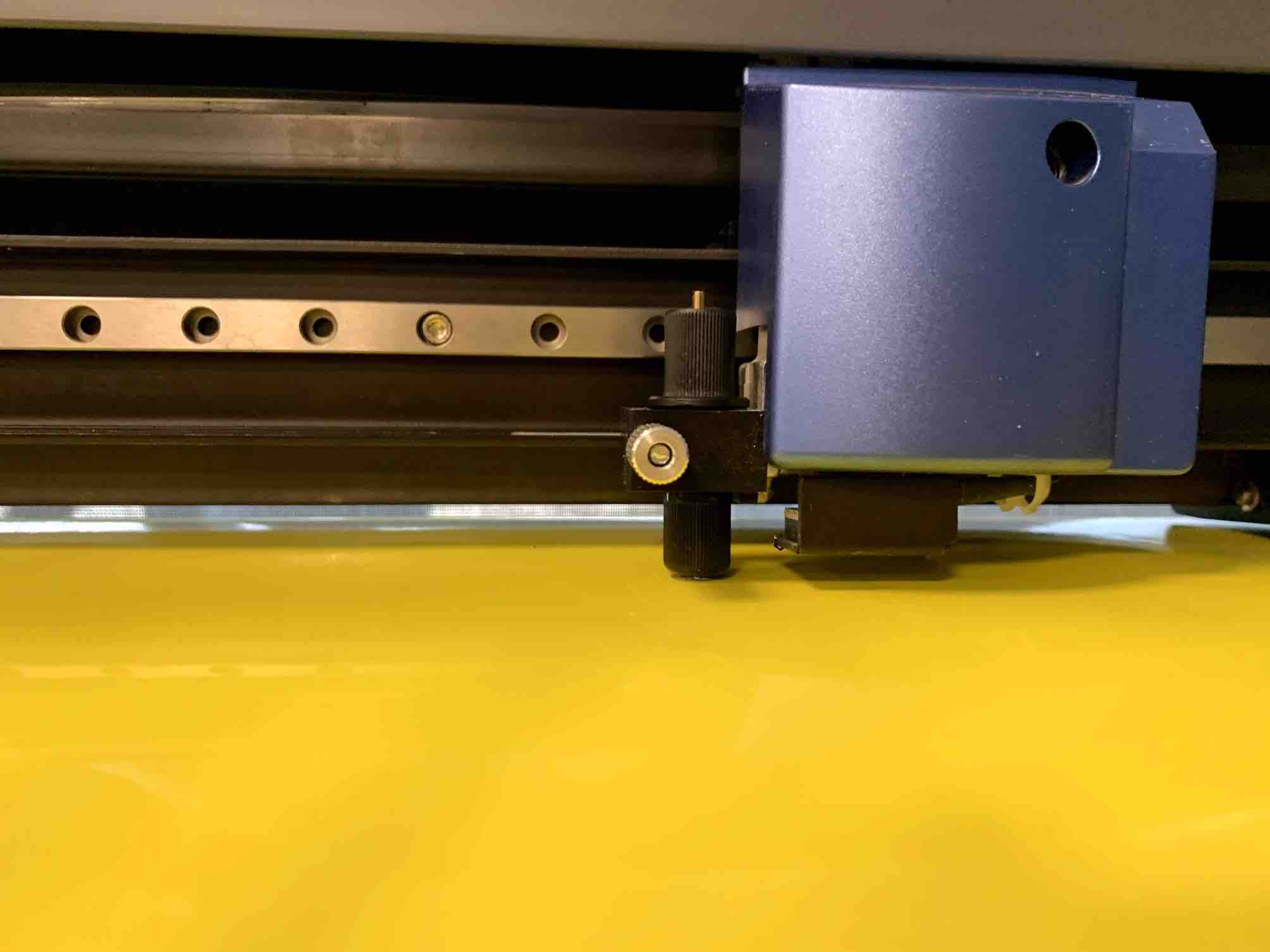
When your document is set up the first step is to take the vinyl to the machine. The sheet slides under the cutter and rollers and on top of the sheet feed shelf.
- Be sure that the roller on each end of your vinyl piece is as close to the edge as you can get without it going off the material. Be sure that each of the rollers holding your vinyl in place are under one of the white bars shown above where the rollers connect. Be sure your vinyl covers the sensor widow as well. These are important steps for the machine to read your piece.
When you have it loaded correctly you can pull the top handle on the left side of the back of the machine. This will drop your rollers in place and lock your material down so that it can be held in place.
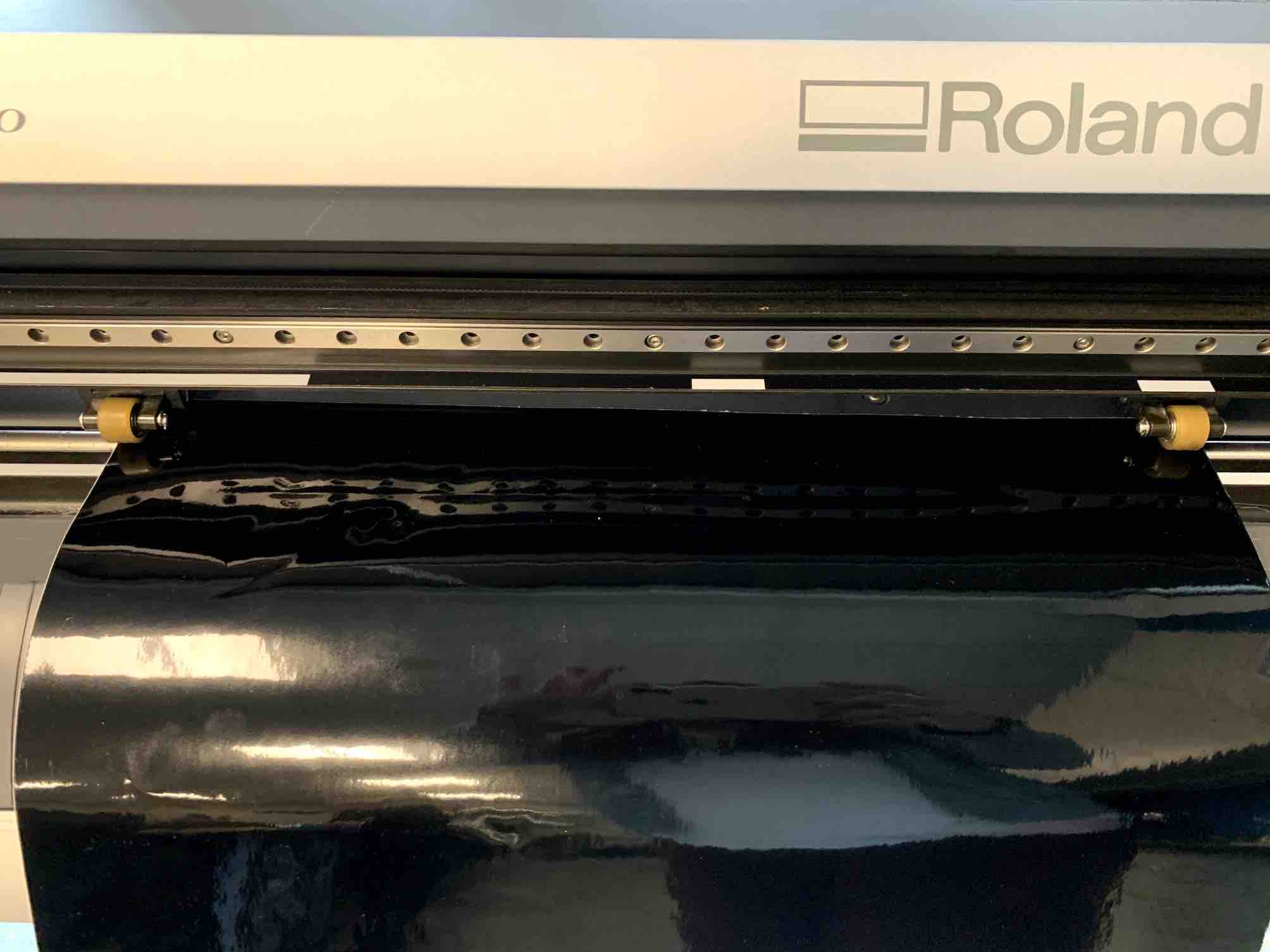
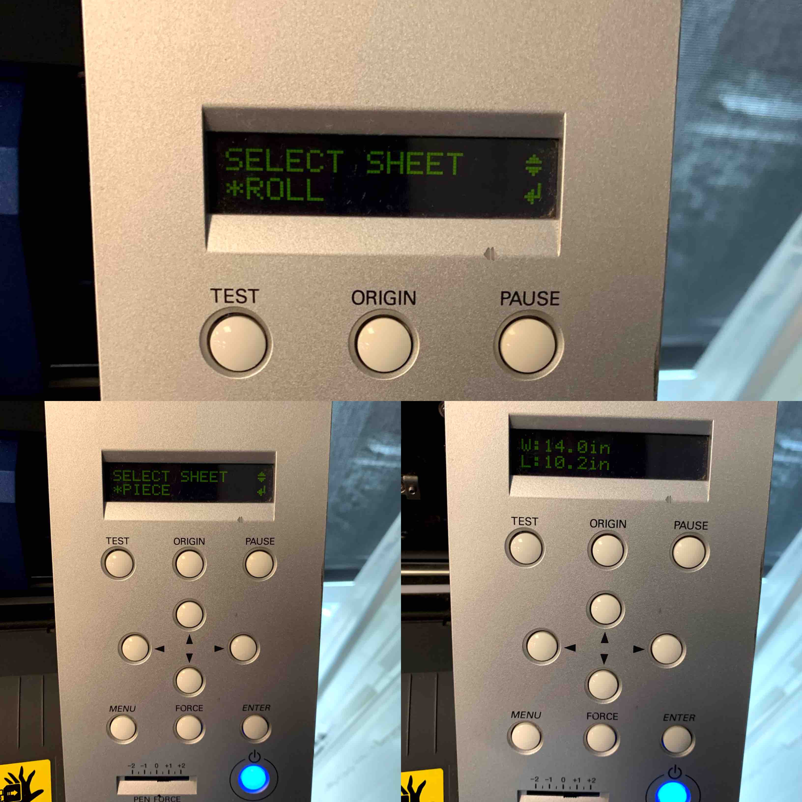
- With your vinyl locked in place the next step is change the screen on the right side of the vinyl cutter to read * Piece instead of the setting of * Roll. This is because you need the machine to provide you with the usable print area. (Each time you put a sheet of vinyl into the machine it needs a boarder of non print area for the rollers to grip the material.) When the screen reads * Piece you can hit the Enter button above the Blue Power Light. This will move the blue box where the blade is. It will also activate the vinyl cutter to begin moving the sheet so it can retrieve an accurate size.
- This is where safety could be the biggest issue. Be sure you do not have long hair down, wear anything dangely and loose, and be sure to pay attention to what it going on. The blade may be small but it can be dangerous and is extremely sharp!
- This is where safety could be the biggest issue. Be sure you do not have long hair down, wear anything dangely and loose, and be sure to pay attention to what it going on. The blade may be small but it can be dangerous and is extremely sharp!
- The next step is to take the provided measurements, in the photo above it reads as W: 14.0in L: 10.2in, and apply them as your material size in the document on the computer. Place the design you are starting with into your print area and select print. This will bring up a print screen that looks just like the gray laser screen. Change your printer option from the current setting to the Roland Vinyl Cutter, and select print. The blade should now be moving over your vinyl piece cutting out the lines (see the video below).
- When the vinyl cutter stops cutting you have to tell it to slide back to its (0,0) point on the far right so you will know the job has been completed. The screen will show an array of measurements. you just want to hit the Menu Button so the screen can read * Unsetup. Hit Enter and the blue box containing the blade will slide to the right to its (0,0) point. You can unlock the handle on the back left side of the machine by pushing it away from the machine lightly. This will lift the rollers and allow you to remove the piece of cut vinyl. Slide it gently out the front of the machine.
- You must push back the handle to unlock the rollers. If this action has not been done when you pull on the vinyl sheet it will hold tension and you will not be able to remove it. If you force it out it could break the machine.
- The first layer is done and now these steps must be repeated for each of the following colors.
- If detail is too small or oddly shaped you may have some print issues. The blade may accidentally pull some of the pieces from the vinyl. This can get caught on the blade or cause damage so be cautious.
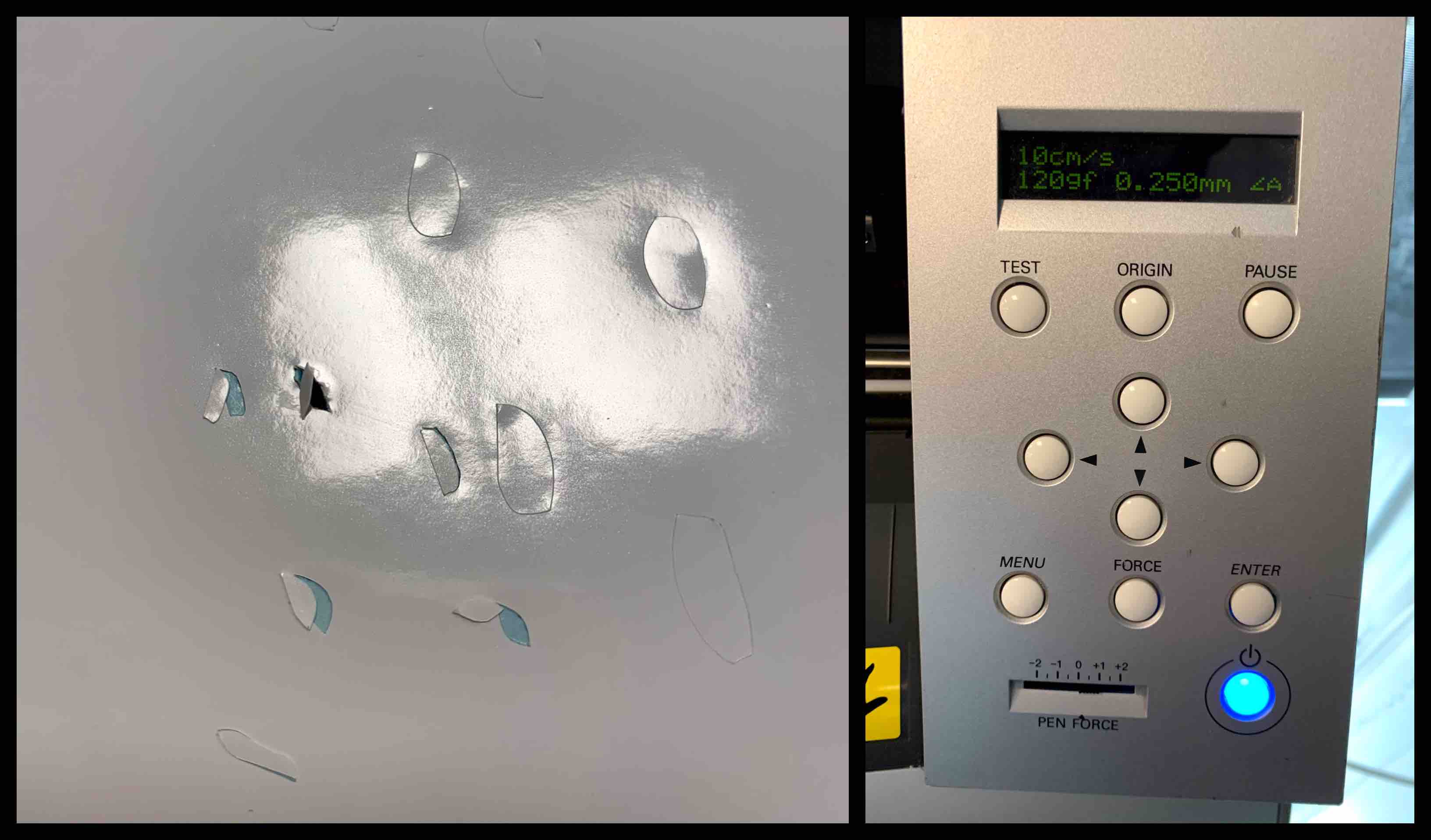
- If detail is too small or oddly shaped you may have some print issues. The blade may accidentally pull some of the pieces from the vinyl. This can get caught on the blade or cause damage so be cautious.
Vinyl Cutter in action - From Youtube
Weeding Vinyl
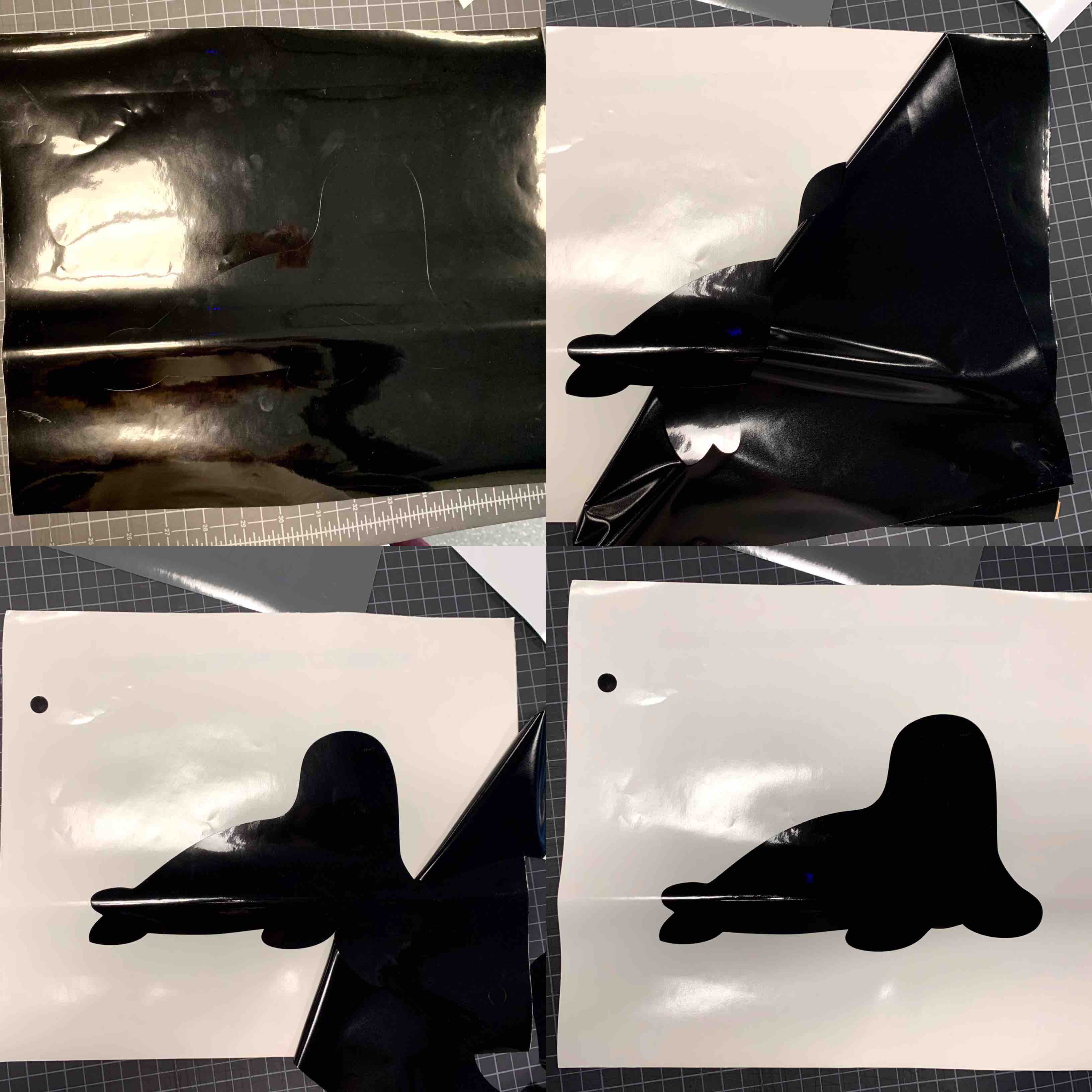
When all sheets are cut in the desired design the next step is the weeding process. The weeding process is the process of remove the vinyl material you do not want in order to reveal the pieces you do want. This could include removing the outside of the design, pieces in the middle or even separating pieces in the design.
- When weeding your vinyl you want to be sure as you are removing pieces that it is not also pulling pieces you want to stay. Sometime if the blade is dull or not setup correctly it may not cut all the way through. In this case having a blade tool around would be handy. Starting in one of the corners pull just enough apart that you can get a start.
- When removing the excess vinyl it is best to pull at a sharp angle. This will help you to keep track of the parts staying and removing, and also help keep it a clean removal. Vinyl likes to stick to itself more than anything and that can be challenging when weeding. Pull at an angle until you desired design is reveled and all excess vinyl is removed.
- Keep in mind if there are registration marks in your design that shouldn’t be removed.
- When these steps are complete you are left with a usable deign.
- These steps should be completed for each layer you have cut for the design. If you design was single colored you would be able to move on to the transfer stage.
Weeding Vinyl - From Youtube
Transfer Process
Since vinyl sticks to itself better than any other material that makes layering your pieces more difficult. There is a transfer process that can help with this. There is a dry transfer method and a wet transfer method. The dry transfer method is good for pieces that do not have a tight registration. The wet transfer method is what I used here do to the tight registration I wanted to accomplish.
- Gather all your pre-weeded pieces. Beginning with your base layer. Be sure it is ready to work with. My base is solid black.
- Choose your next layer. Laying your next layer separately from the first. You will then retrieve the transfer tape. There are two types. The simple transfer tape is slightly opaque. The wet apply transfer tape is clear to help align the pieces of the design. In sections slightly overlapping cover the second layer with transfer tape. Run the wedge over the transfer tape on your design to push all the air out and strengthen the connection.
- When there is a good bond between the vinyl and the transfer tape you can peel it away from the backing. This will expose the adhesive on the other side.
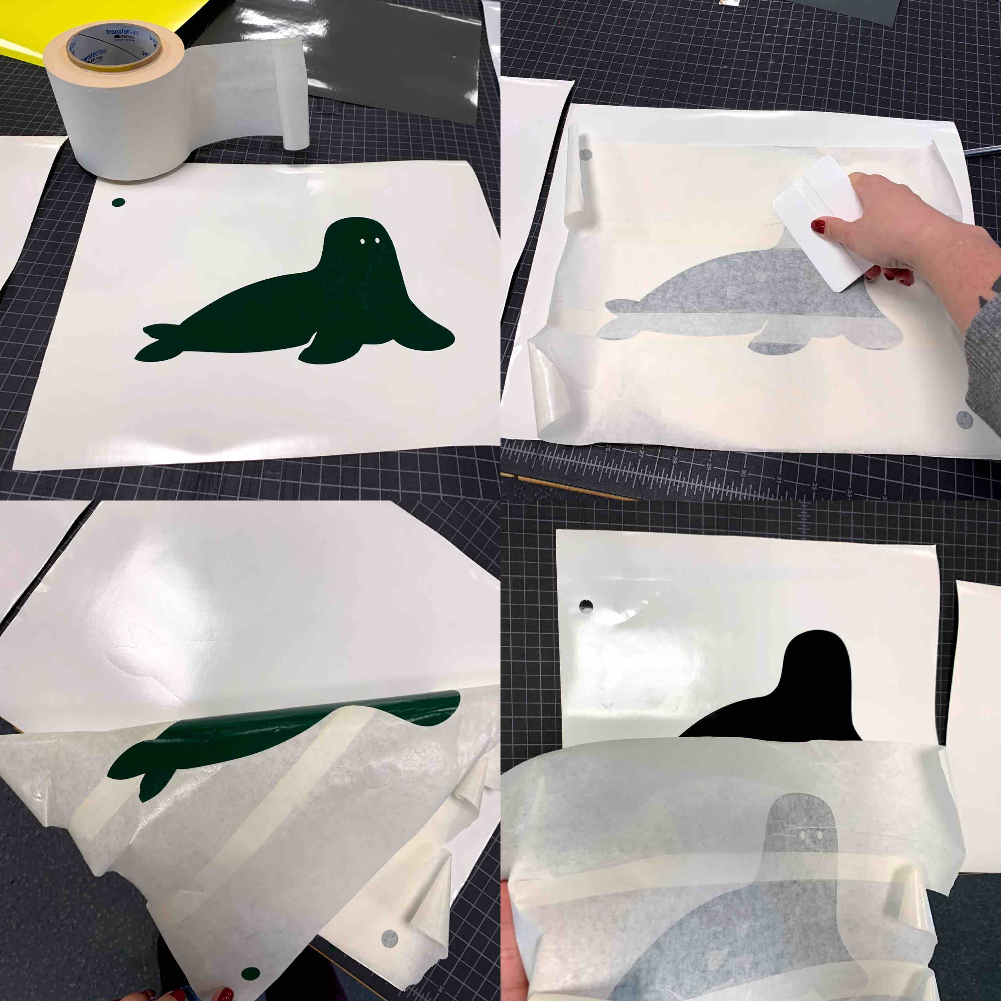
- You then want to apply the wet chemical. This chemical allows you to lay down your layer and if it is not quite where you want it you can make some minor adjustments before it adheres to the piece below.
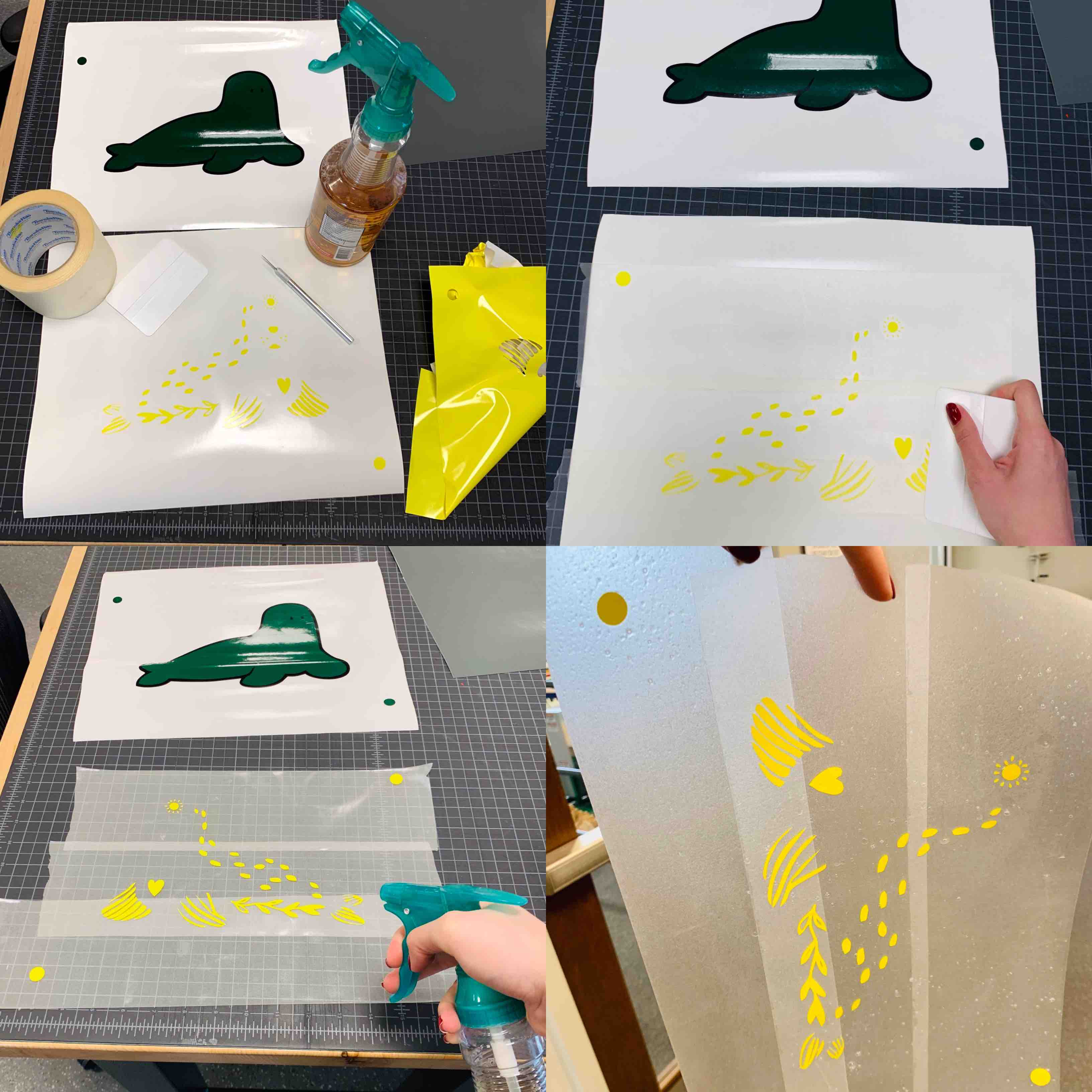
- When all pieces are put together you will have a finished decal to enjoy!
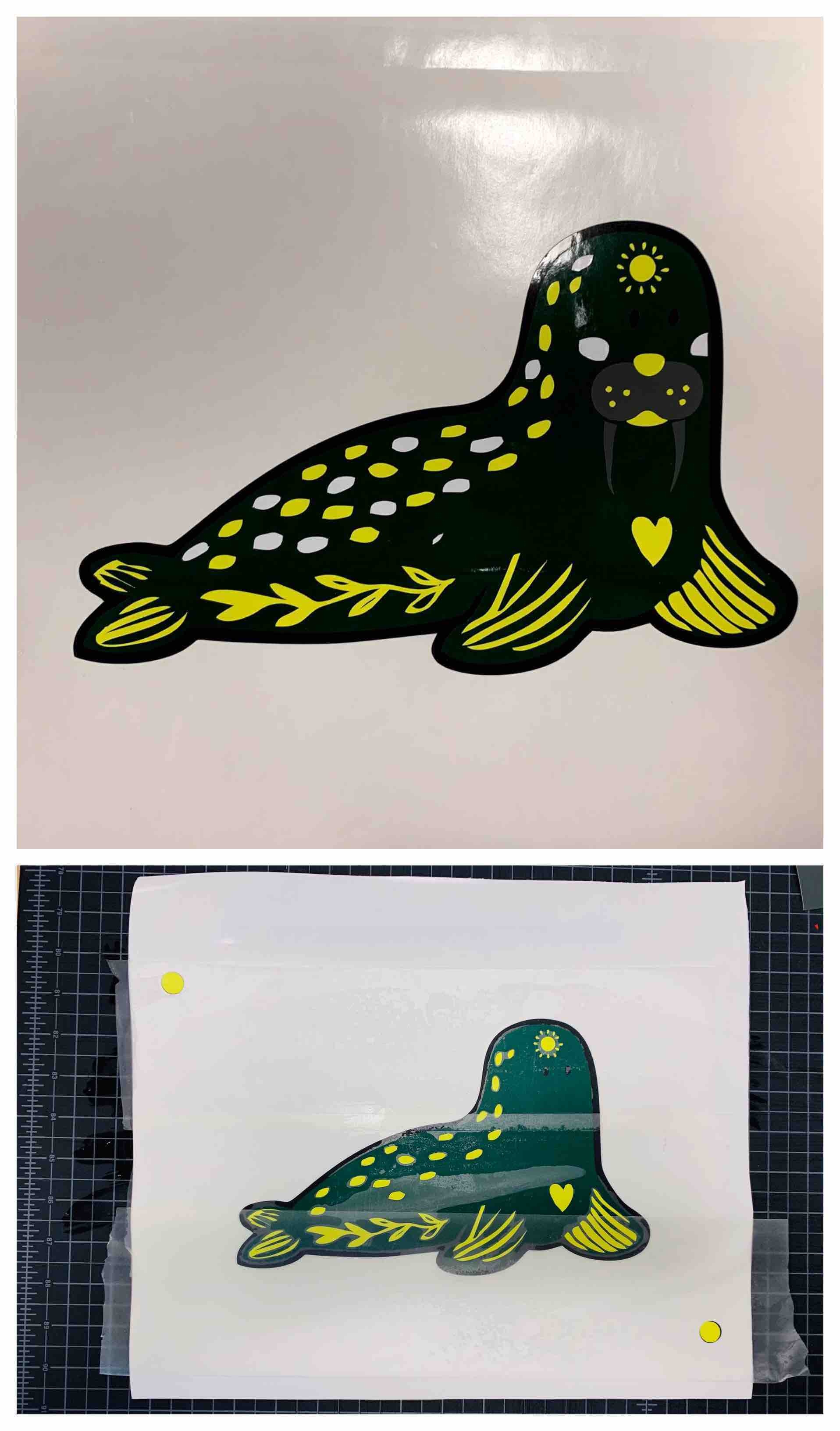
Applying Vinyl Decal
When you apply your decal to a surface you want to be sure to clean the surface. This will help keep the adhesive bond strong. You will use the same process you used to transfer the layers together.