5. 3D Scanning and Printing
This week I worked with 3D printers and scanners. We were assigned a group assignment, as well as an individual assignment.
Research
Our research consisted of defining the machines, parameters and functions of creating a 3D print. We were challenged to create a 3D print from an .stl file we designed and from a 3D scan of an object. Below you can find the group research.
Group Assignment
The group assignment was to test the 10 design rules on our printers. At the LCCC lab we have a wide range of printers. We decided to run as many tests as we could. We wanted to document the limitations of our 3D Printers.
Useful links
Individual Assignment
Our Individual assignment was to use a 3D software to design a print that could not be easily created subtractively. One of the design parameters was that it was only a few cubic inches to be sure that there was enough time to complete the assignments. The other part of this weeks assignment was to 3D scan an object and prepare it to print - the printing itself was optional.
Design of the 3D Piece
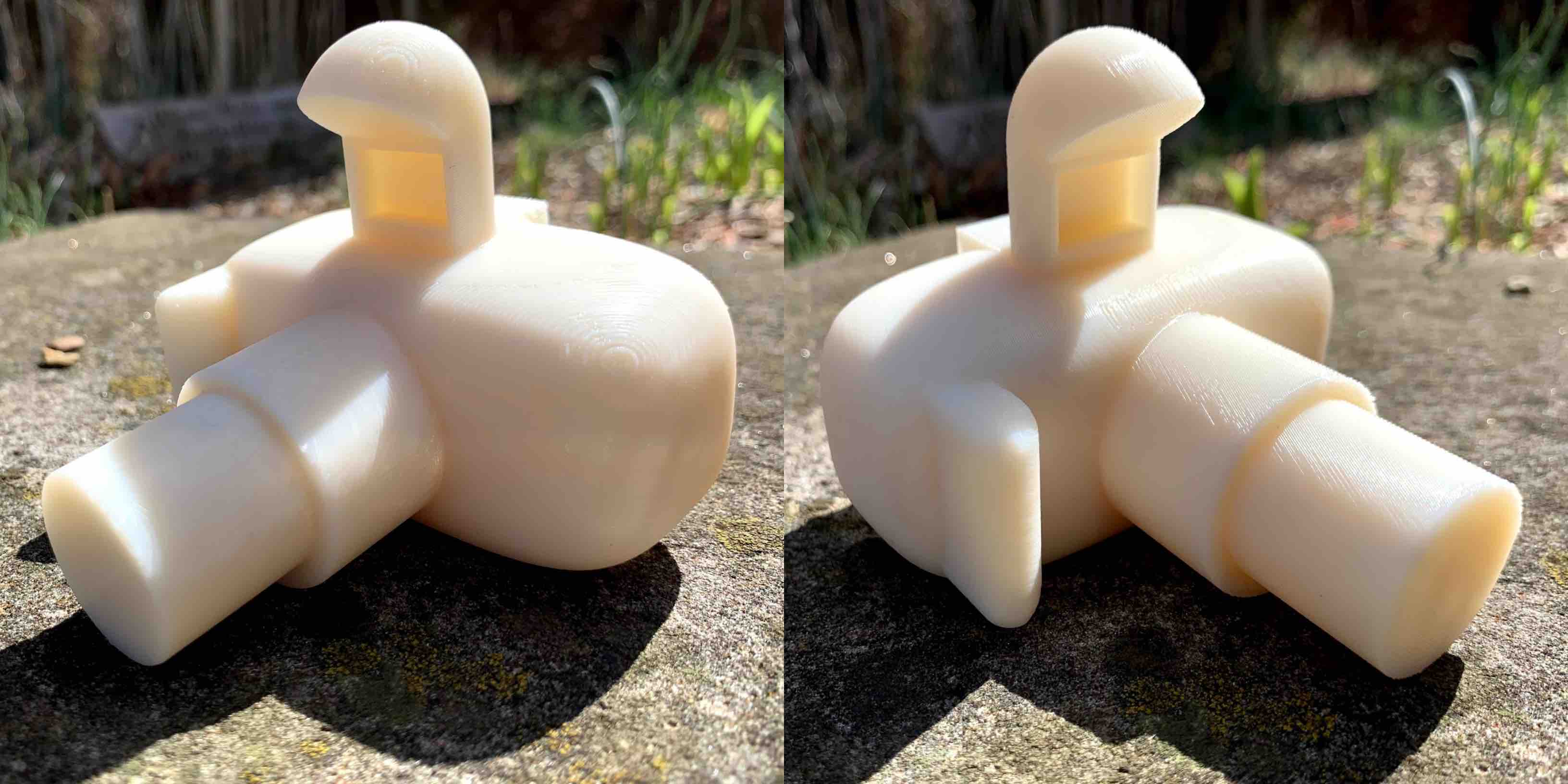
The first step I took to complete this weeks assignment was to design something in a 3D software that could not be easily made subtractively. I decided to create a model of a camera. I included rounded edges, overhangs, indented pieces and extruded lengths.
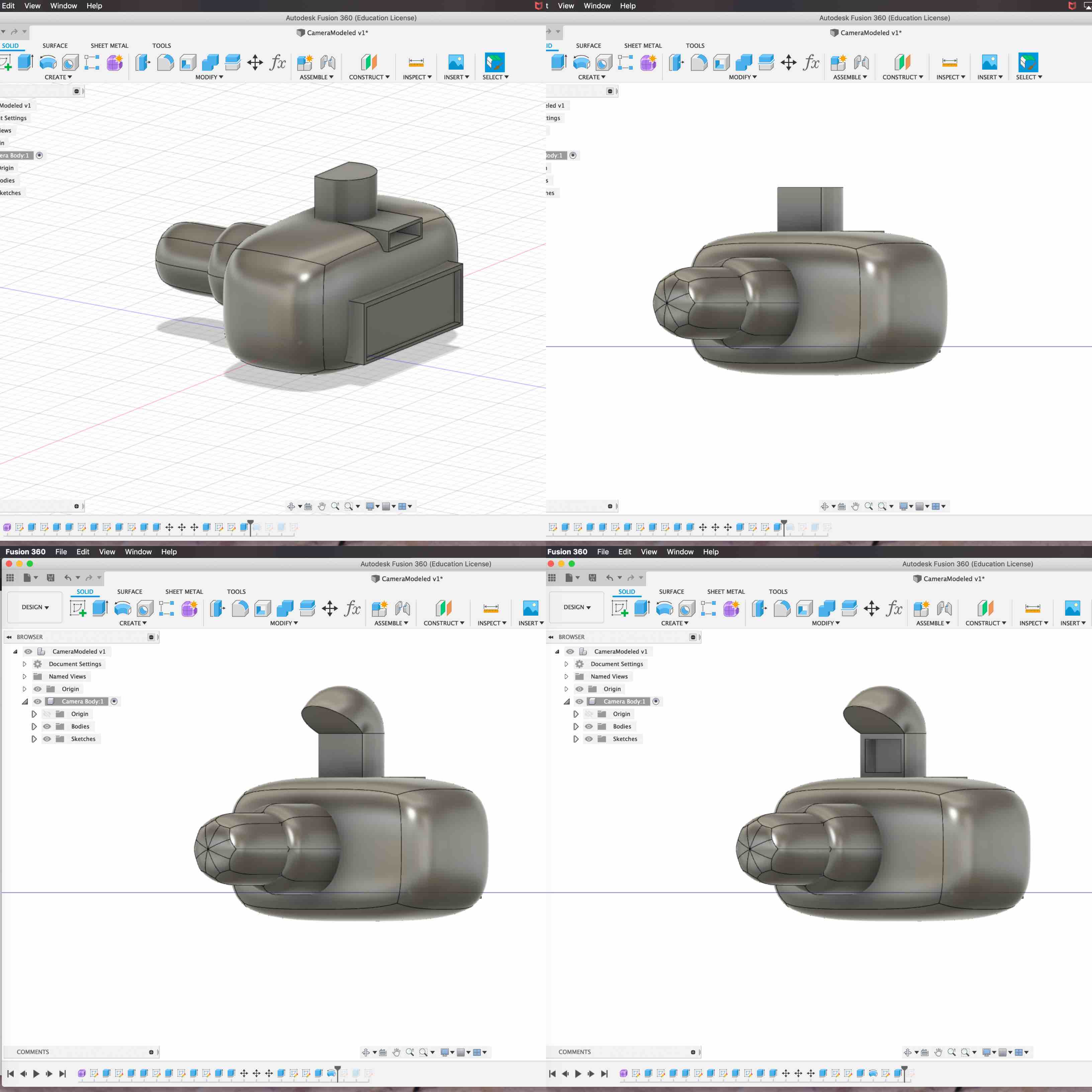
- The first step was to create a sketch on a plane. I decided to use Fusion 360. Fusion 360 is a program I have never used before this class and one that I would like to continue becoming proficient in. I wanted to challenge myself to create an object that had to challenge the printer. As I designed my piece I kept this on mind. Knowing that rounded edges can be a bit more challenging than just straight sharp shaped objects I decided to create a form using the purple form option under the create tool kit. This create a form option allowed me to design the camera body with rounded edges. I used the same function to build forms off of the front face of the body to create the lens. I created a zoom lens that has the additional extension.
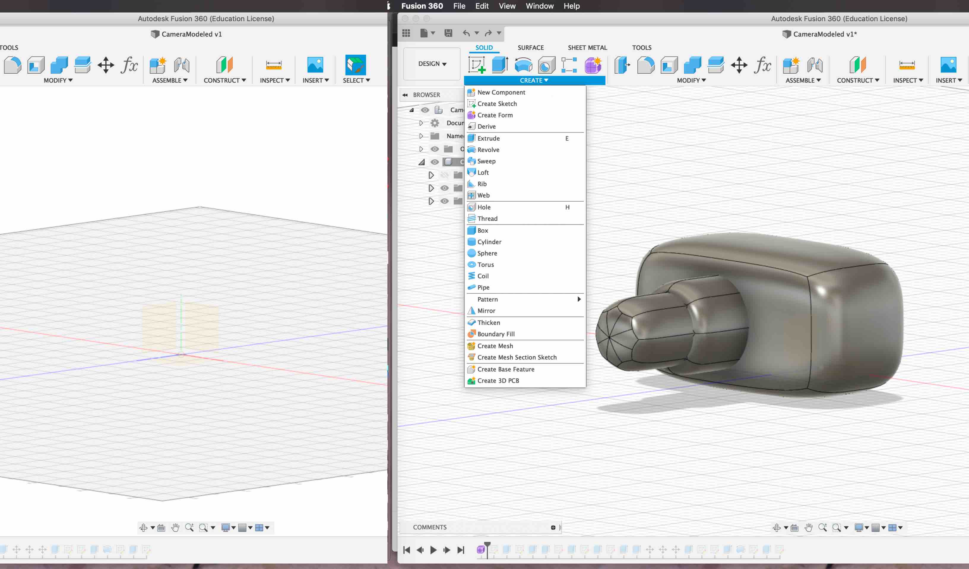
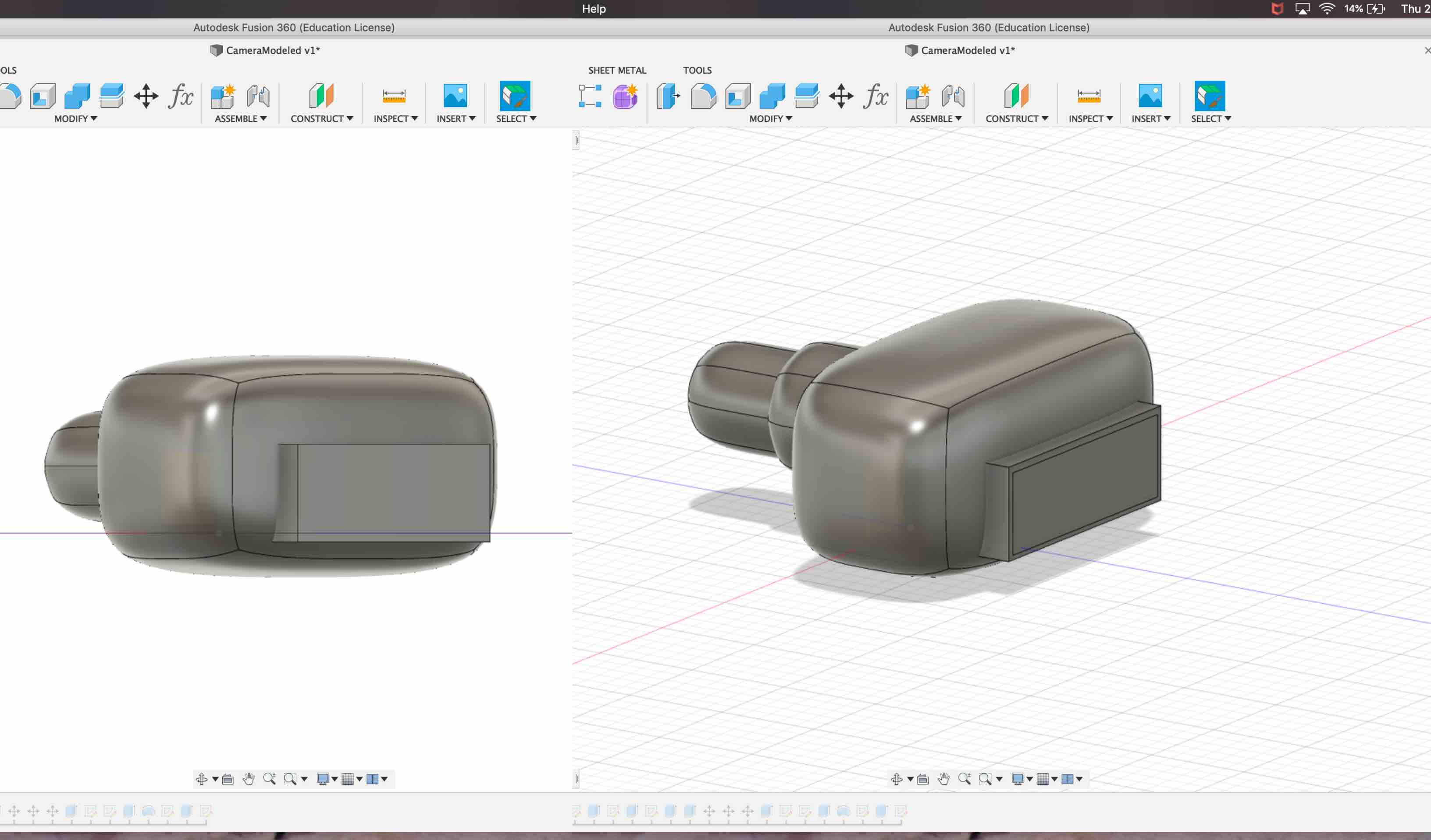
- With the body and lens created using forms I decided to work on including some sharp components. I wanted the back of the camera to be recognizable so I decided to create a representation of a display screen. On the back of the form I created a sketch. I used the two point rectangle to make the shape and extruded it out the back of the form. I set it to extrude and create new body, instead of cut out or join options. This made the basic shape, however I wanted it more detailed. I decided to create another sketch onto my new body. I used the two point rectangle and created one that would fit within the first, leaving a boarder. I then extruded the smaller rectangle into the shape of the larger one, choosing to cut out the shape. This added a shallow detail making it seem more like a display screen. This also helped to test the limits of the machine. This represents a similar build system of a bridge.
- I decided to add more detail to the back to make it more recognizable. I started a sketch at the top of the form I created. I made another two point rectangle. I extruded it out the back of my shape and set it to create a new body. I started another new sketch onto that two point rectangle and made another smaller one placed inside. This I extruded a cut out through the center. This cut out being smaller and further back into the model. This helped challenge the printer limitations more and created a view port representation.
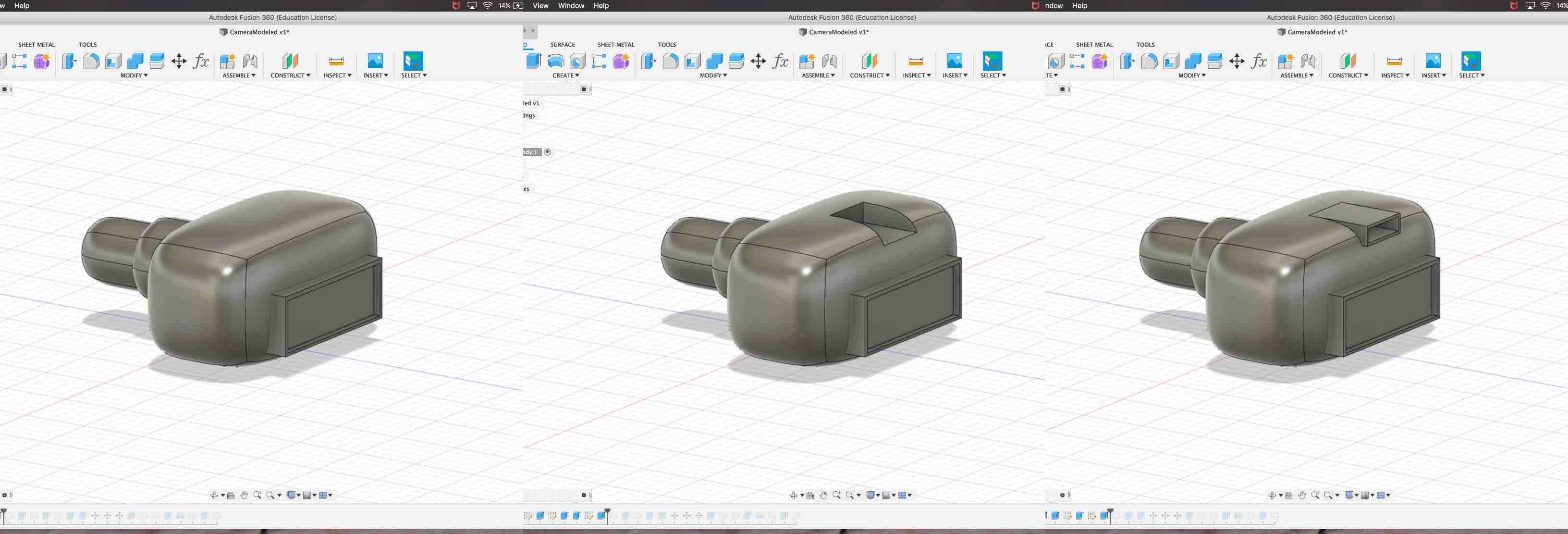
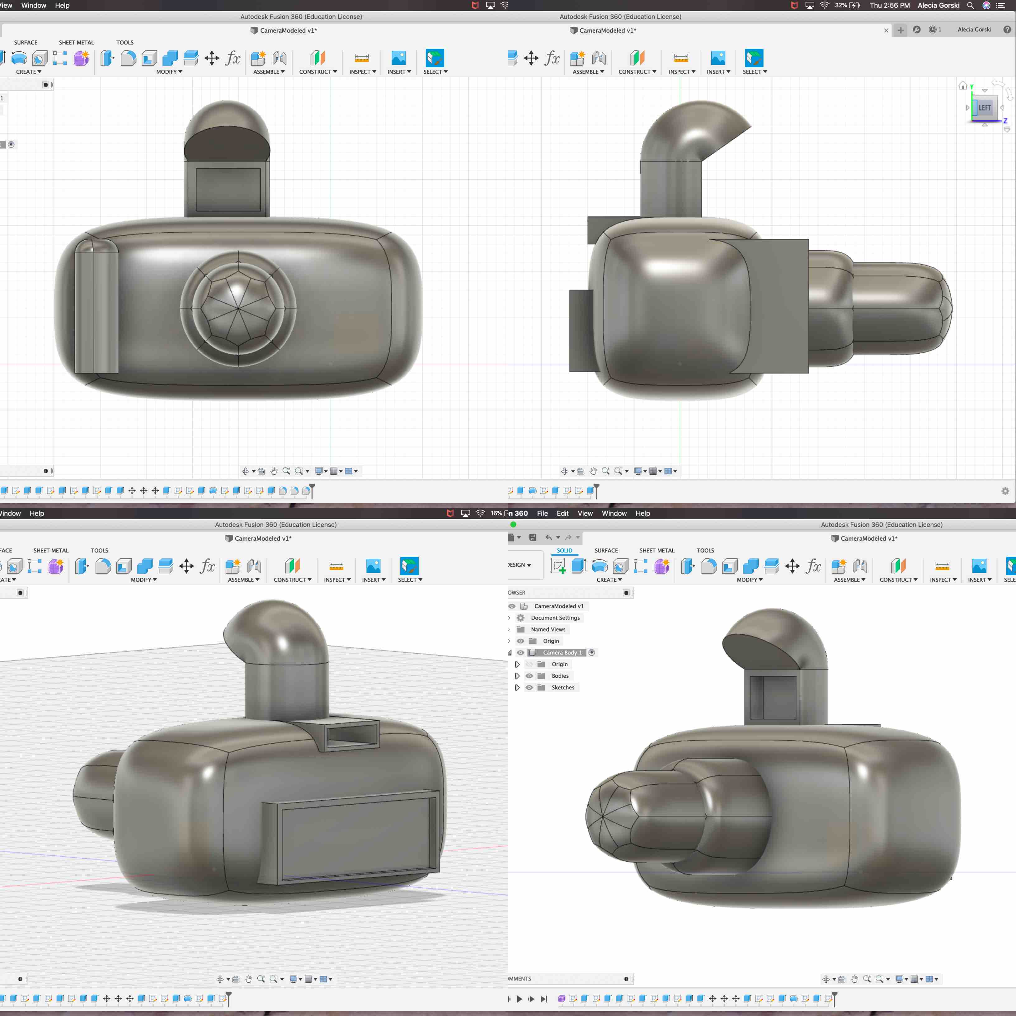
- My next detail I wanted to work on adding was a representation of a flash. I found this to be quite complicated. I wanted create a shape that I could use the revolve tool with to rotate the top and create an overhang. This could represent the flash of the camera. In order to do this I had to Create a half-circle. I used the line tool and the arc tool to create the desired shape. I sketched it on the top of the form. I then extruded it as a new body out the top of the camera. When the shape was extruded out it had a flat top. This is where I then used the revolve tool. I selected the top of the new extrusion and applied the create tool Revolve. This allowed me to rotate the top of the half-circle on the flat line as an axis. This rotated the shape around and created the desired overhang for character. I then decided to add another indent. I wanted to apply this under the overhang of the flash to add detail. I created a sketch on the face of the rectangle located below the revolve of the flash. I then created a two point rectangle. This was extruded into the body and cut out to create the depth.
- I then rotated the view around and decided there was something missing on the front of the camera. Most camera bodies have a grip that sticks out to help the photographer to grip the camera. I started a new sketch on the left front of the camera when facing it. I then created a two point rectangle. I extruded the shape out the front of the camera form and made it a new body. I then used the fillet tool on both the left and the right sides of the new body and pulled them in, rounding them out.
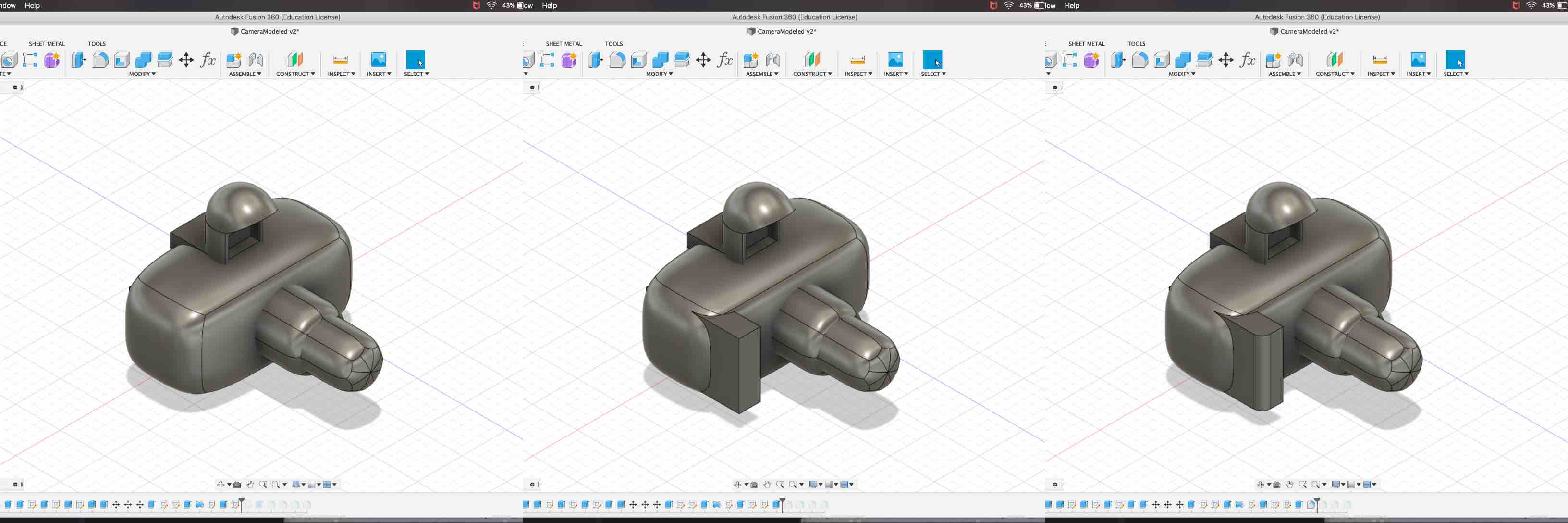
- The final modeling step was to round off the top and the bottom of the grip I just created. I again used the fillet tool under modify. I selected the edge I wanted to work with and pulled them in to round the shape.
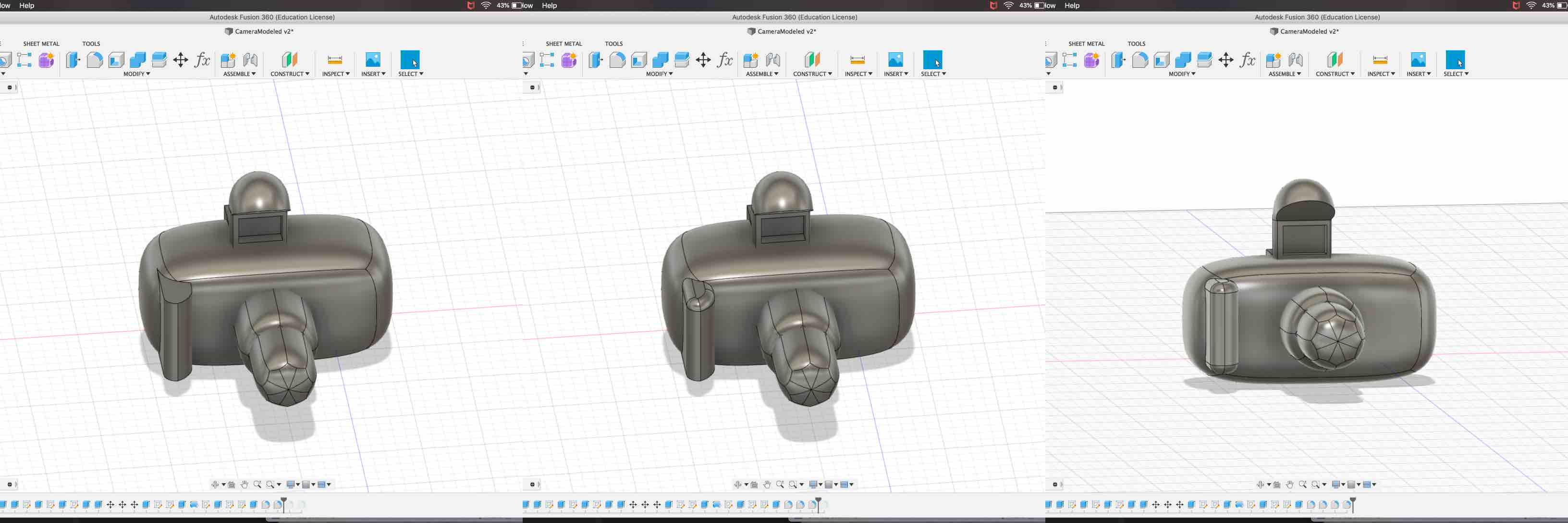
- In the end I was pleased with the overall look. Knowing we only needed to print something small, I wanted to challenge the print job with overhangs, indents and rounded surfaces.
Printing 3D Piece
The next step of the process is to take your new model and save it as an .stl. An .stl file is a file the the 3D printer can use to communicate with the model and read the print correctly.
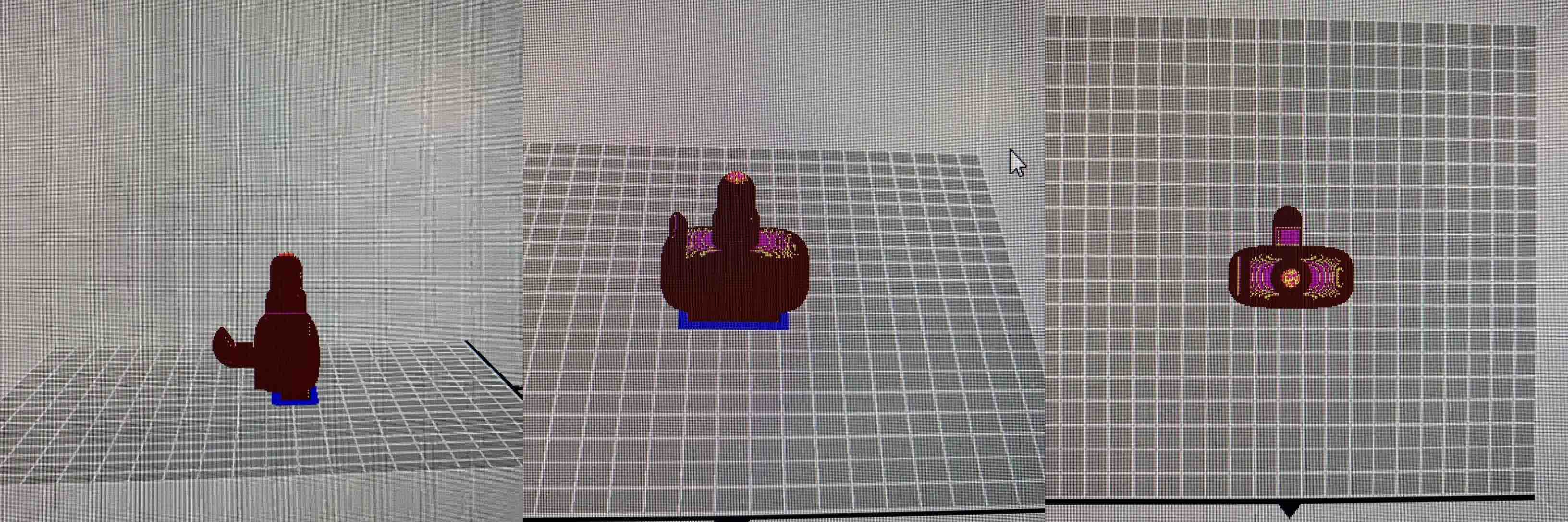
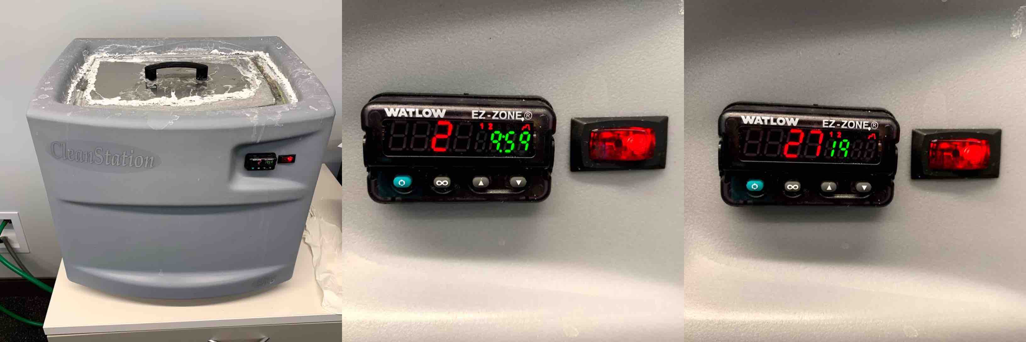
- Step one in this process was to open my .stl in the Sindoh printer software I decided to use. I chose this so that it would communicate with the printer. This Sindoh printer is newer to our labs and I wanted to get more familiar with its limitations. It is an enclosed unit that helps eliminate environmental factors that can effect a print such as moisture and air movement.
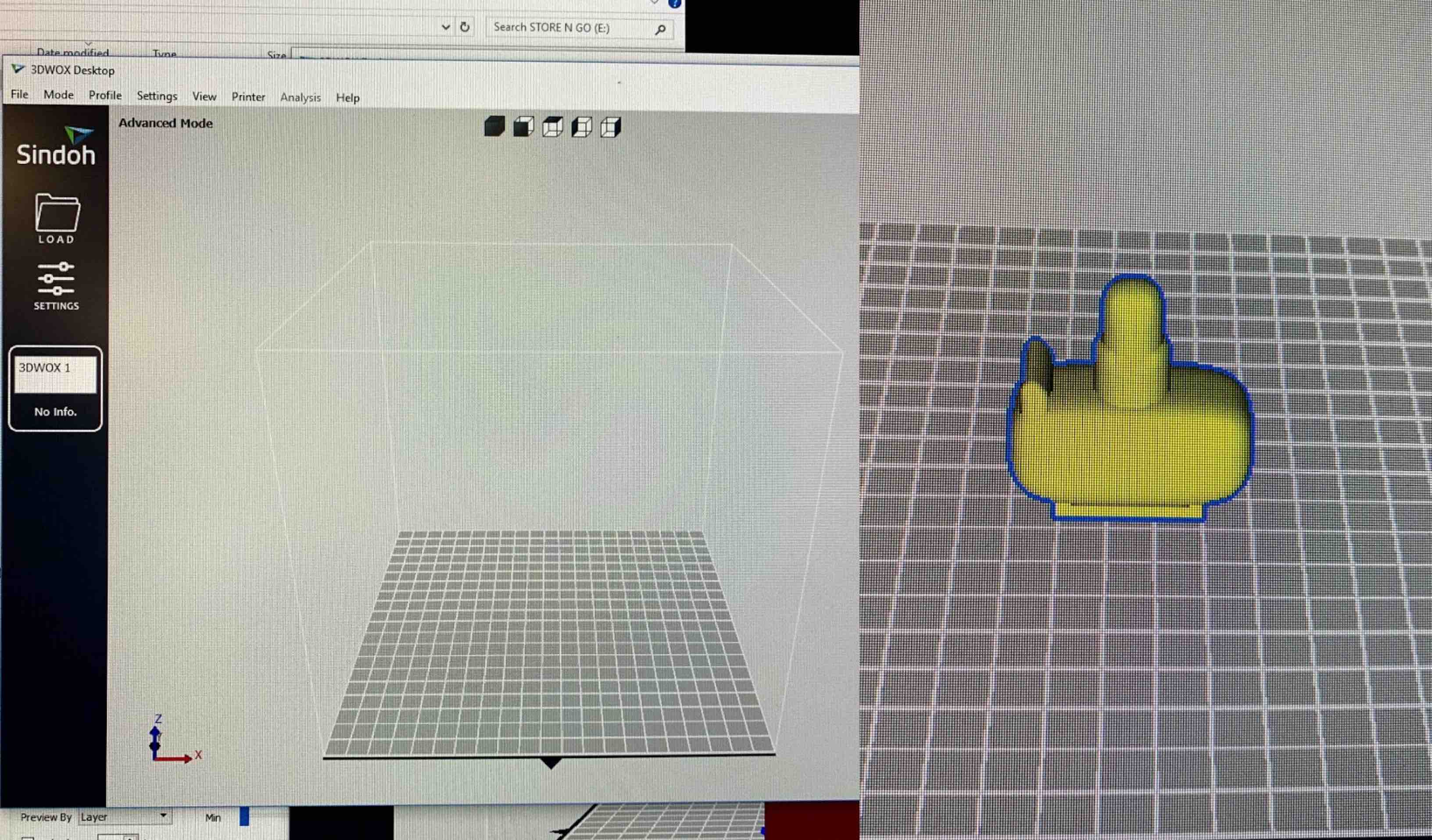
- Once I loaded the .stl into the software I had to make sure it was loaded and oriented in the direction I wanted. I did not want to use support material so that I could see how the print would lay down on its own. Once I was happy with how my piece was laid out I pulled the flash drive from the front of the printer I chose to use.
- I loaded the flash drive from the printer into the computer where I had the software open. I then used the Sindoh software to save the g-code of my file to the flash drive.
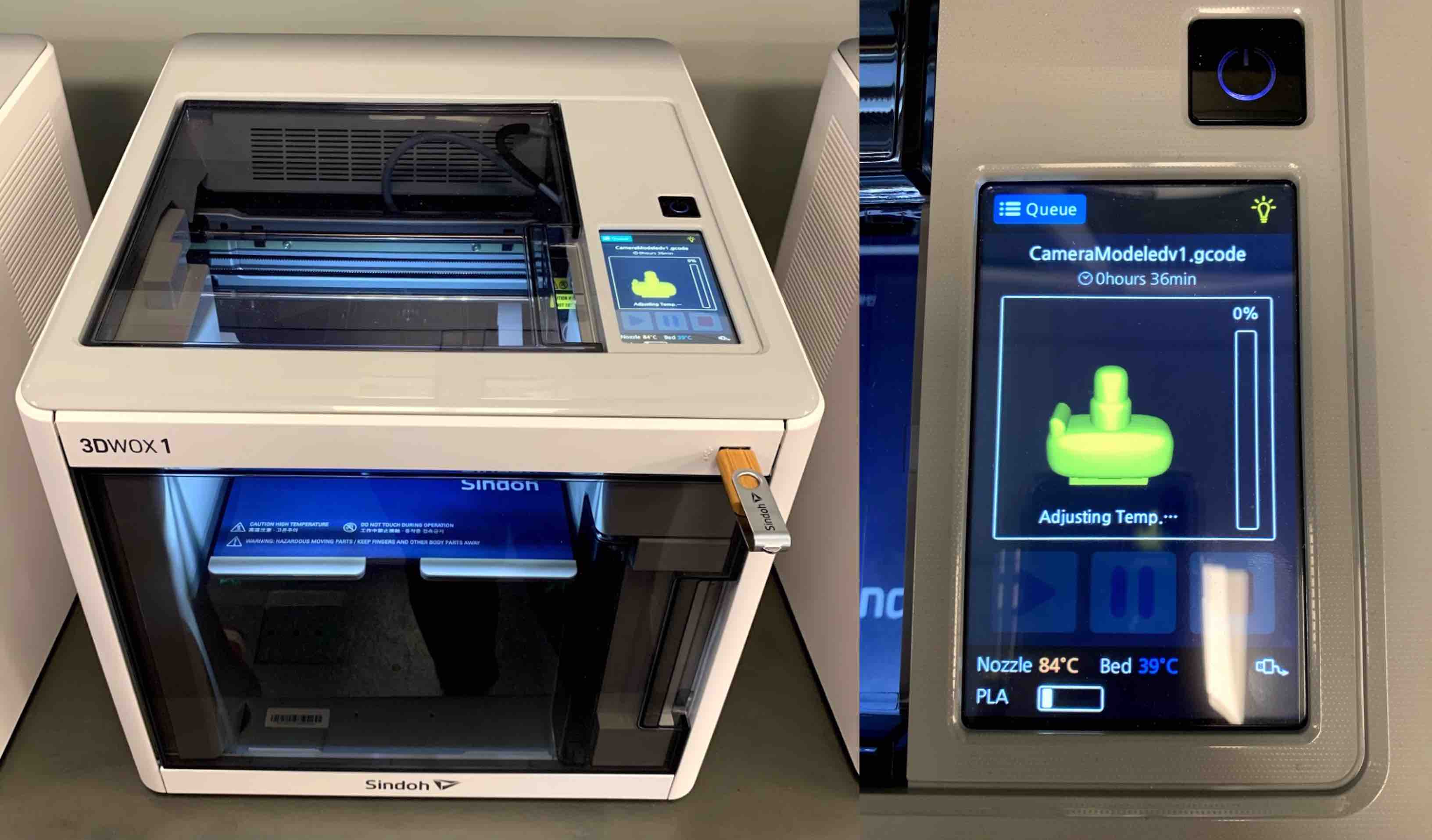
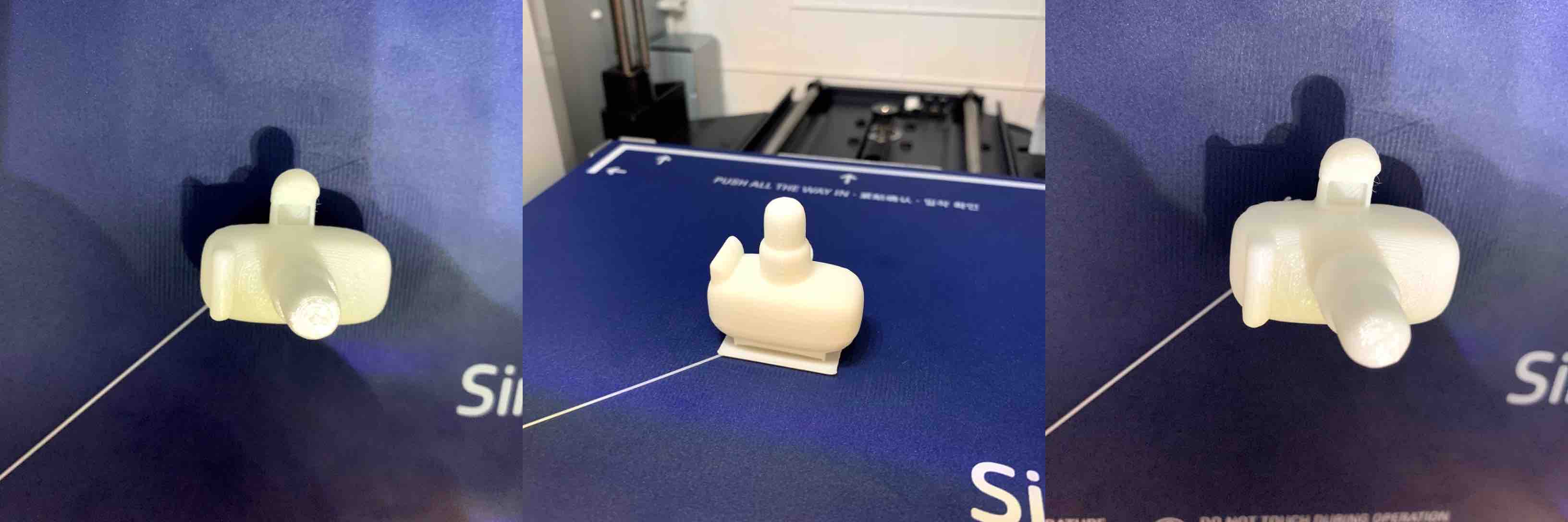
- The g-code is the coding that the machine uses to process the print. The g-code tells the machine where to move, extrude and what parameters to work with. I plugged the drive back into the front right top of the machine where the USB port is located and the machine loaded the drives information. I chose the g-code associated with my piece and the printer provided me with a preview of my print as well as estimated printing time, color of filament, bed temperature and nozzle temperature. When the file is ready I pressed the play button and the printer began its work.
- The g-code is the coding that the machine uses to process the print. The g-code tells the machine where to move, extrude and what parameters to work with. I plugged the drive back into the front right top of the machine where the USB port is located and the machine loaded the drives information. I chose the g-code associated with my piece and the printer provided me with a preview of my print as well as estimated printing time, color of filament, bed temperature and nozzle temperature. When the file is ready I pressed the play button and the printer began its work.
- When the job is ready to run and Ive pressed the play button on the touch screen the printer begins its start up process. The printer first heats the nozzle and bed to the correct temperatures. The Nozzle should be around 200 degrees Celsius and the bed should read around 60 degrees Celsius. Once everything is set to the correct temperatures it will start at the bottom corner of the bed and draw out a thin line of filament to the starting point of the print.
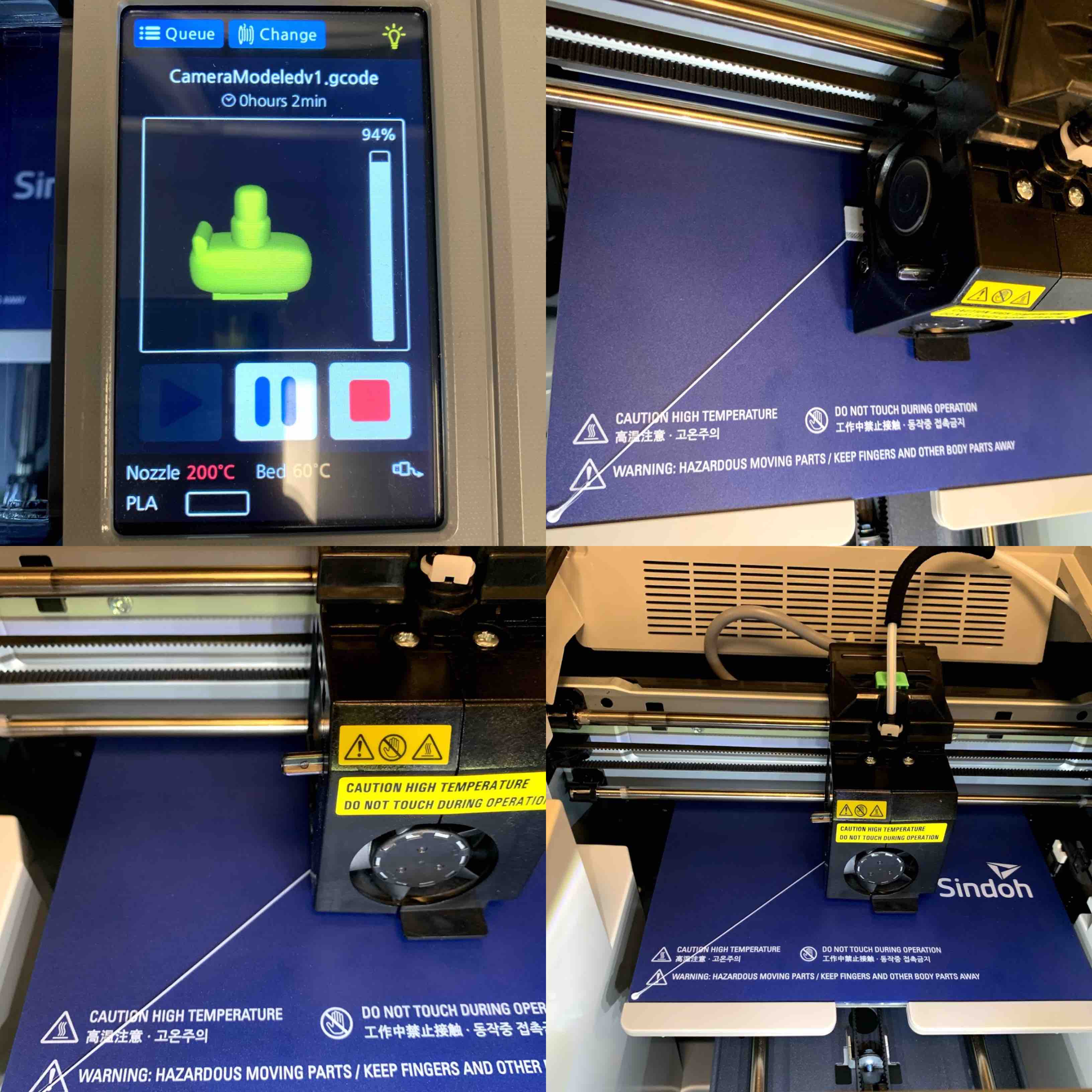
- The machine continues until the print is finished. The printer head moves on a x and y axis while the bed moves on the z axis. This allows it to meet the requirements of the print. Once the print is finished I waited for the bed to move down and the printer to cool before moving on to the removal step.
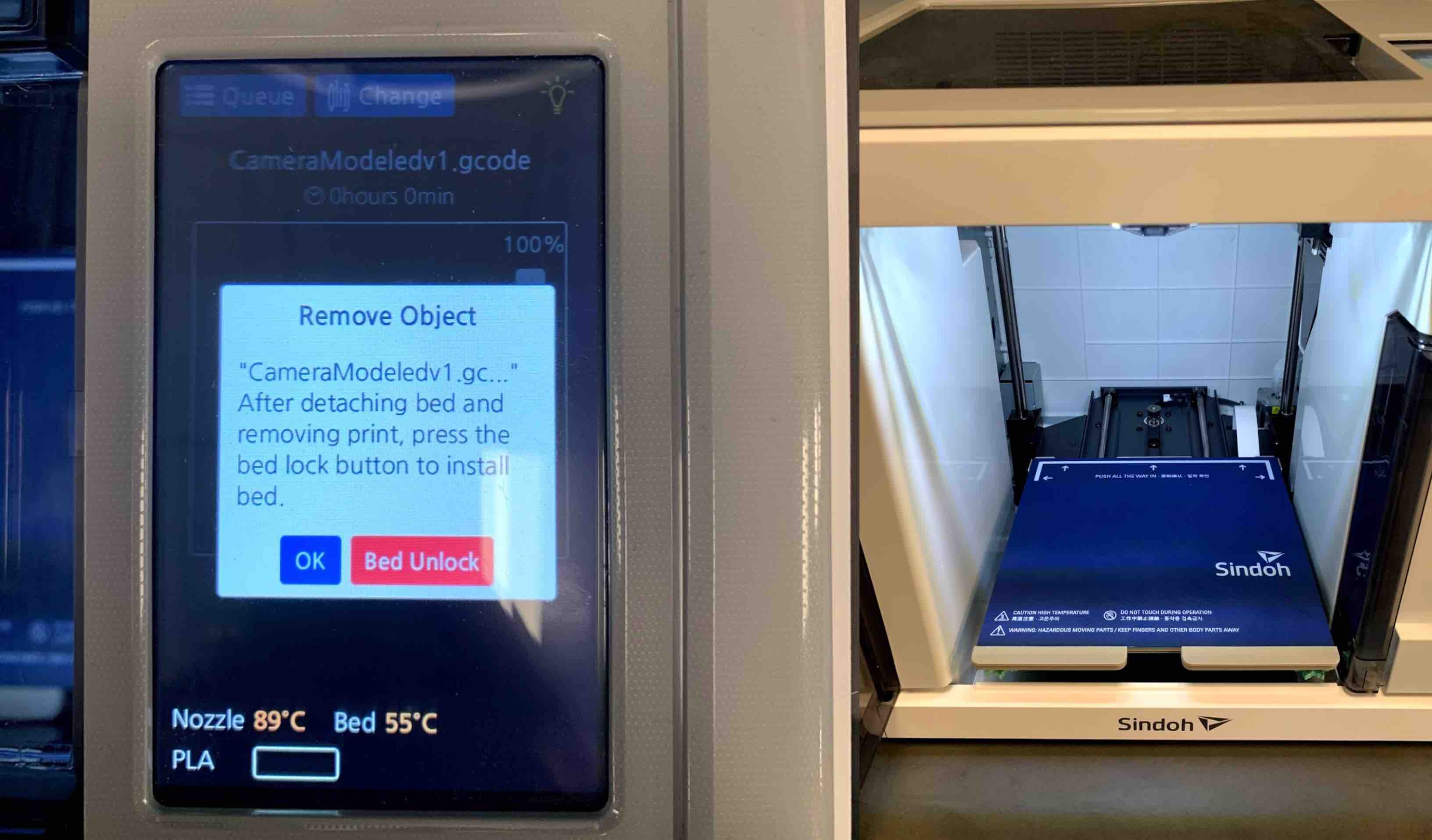
- When everything has cooled down it was time to begin the removal process. I started by unlocking the bed. The bed is magnetized to the tray. I pulled on it lightly and removed it from the printer. Once removed I was able to bend the bed slightly to loosen an edge of the print. I then used one of the red plastic spatulas to pry the piece carefully from the bed of the printer. Optionally the spatula does not need to be used to remove the part from the tray each time. By bending the tray more aggressively the parts can be pulled from the surface of the bed. This can reduce surface scratches and damage to a 3D print and printer bed.
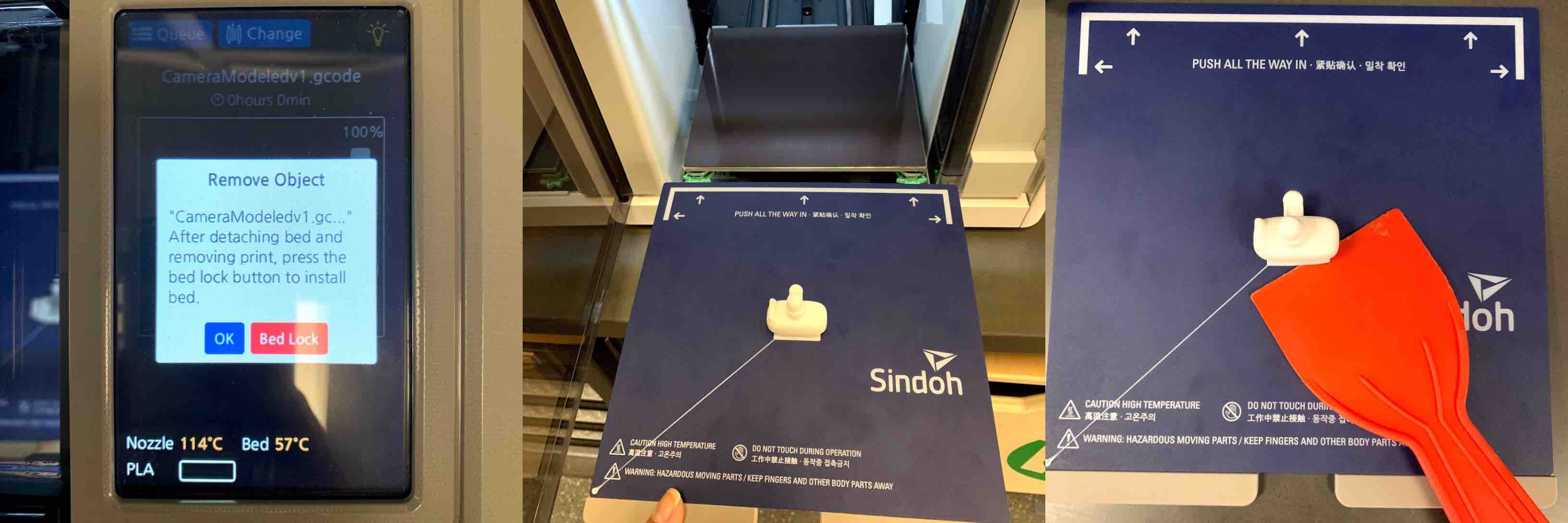
- After removing my piece there was one more step to finish using the printer. I then had to place the magnetic bed back onto the tray and lock it back in place using the touch screen.
Print Starting on Sindoh: From Youtube
Print Finishing on Sindoh: From Youtube
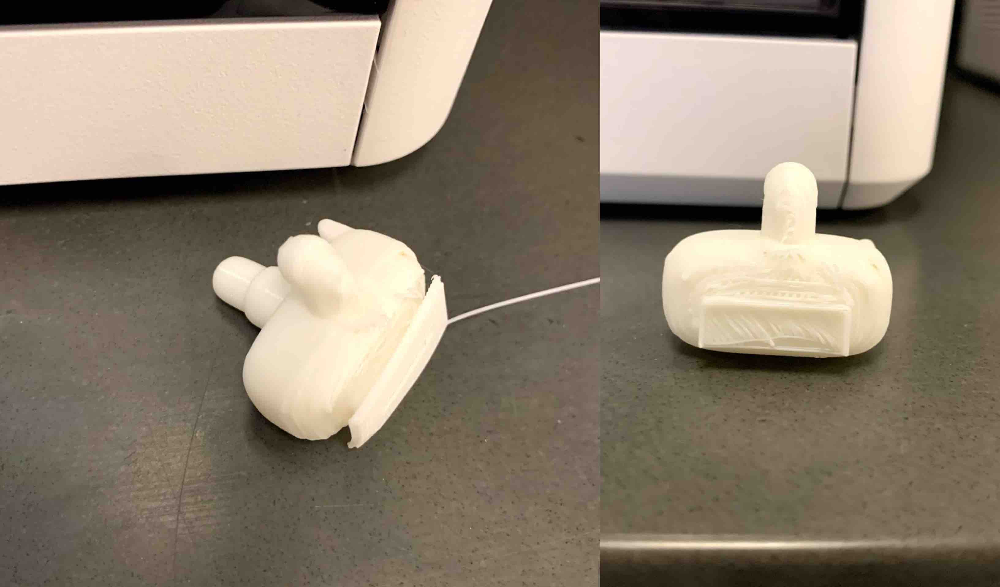
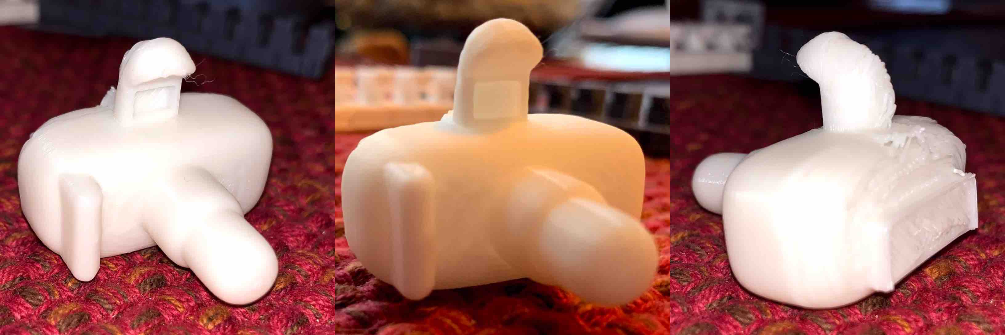
Hero Shots of 3D Print
Once my print was done I was overall pleased. There were a few complications and a solution I did try listed in the category below labeled Individual Project Complications and Solutions.
Adding More Complexity
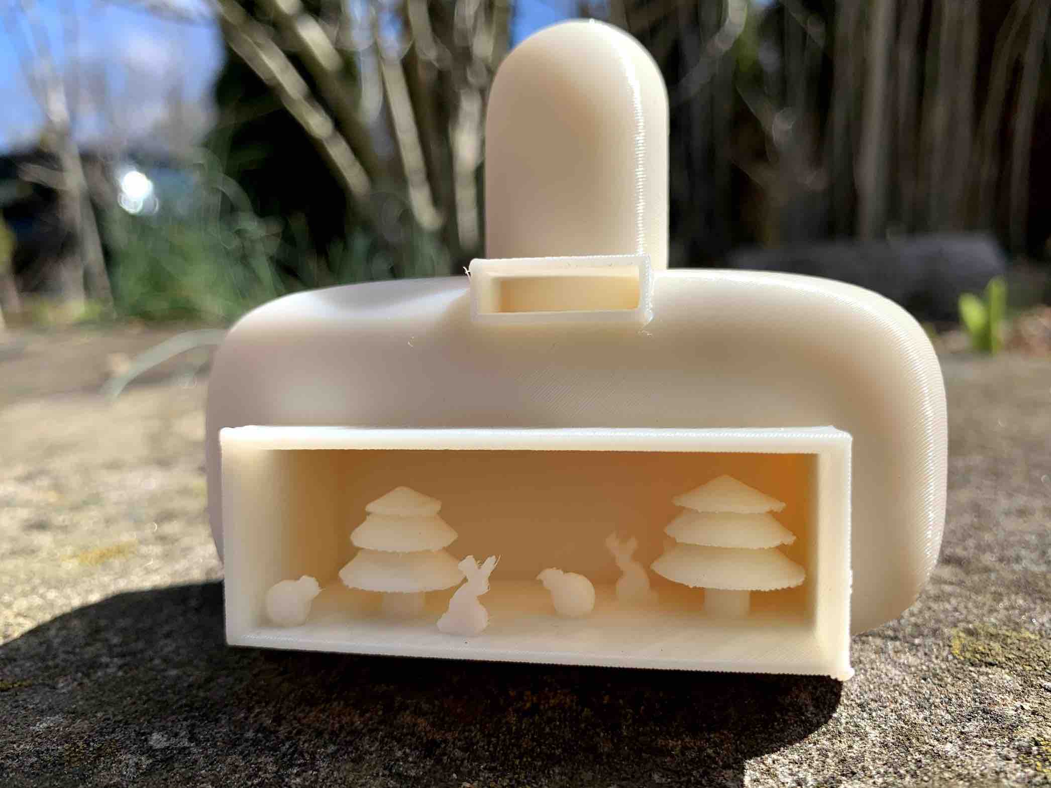
When discussing my final project I realized that it didn’t seem to be as complex as I had originally thought. Although it was a challenge to model, it did not quite meet the requirements of the overall assignment. With a closer look I could see that it could be machined with a subtractive process. To add complexity I decided to design the view finder to be a clear box. Inside the box would be a number of loose components that would represent subjects that could be found in a photograph.
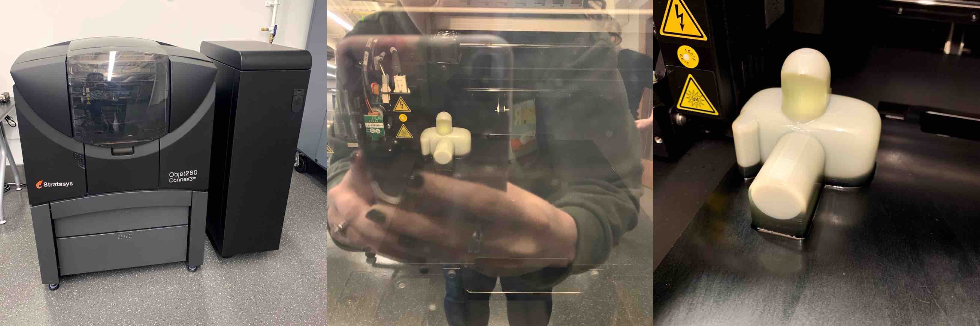
The Stratasys Objet 260 is a larger 3D printer. It uses a liquid resin and cures with UV Lighting. It prints like an ink jet printer by placing droplets of the material in the correct position and then curing each layer as it goes. It prints the support material with the modeling material, all in one layer. The support material then cures in the consistency of gelatin while the build material cures more rigidly.
Printing Model on Stratasys Objet 260
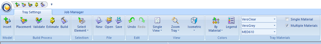
To begin using the machine I had to have a file that communicated with the 3D printer. I used a software called Objet Studio.
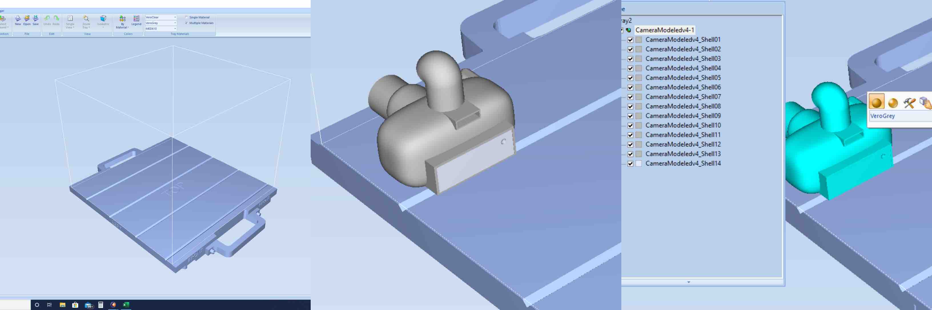
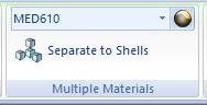
After opening Objet Studio I imported my file. This was done with the tool bar in the top left side of the screen. With my part loaded in I could see that it was imported as all one piece. However, in order to assign different materials to different components it has to be separated. I found that there is a tray window that lists different layers. In order to allow the program to understand which layer I wanted to be which certain material I used the “Separate to Shells” option. With my part selected the program broke it into the layers I had built in Fusion 360.
This now allowed me to assign different materials to each different layer. I decided I wanted the box I built inside the view finder to be clear. This would represent the clear screen of the view finder as well as hold the loose components within the print. I modeled a hole in the top corner of the box to allow the PH bath to dissolve the inside support material. The camera components and the loose components were printed with the same gray modeling material. Using the tray list and the upper tool bar I set each piece to the specifications desired.
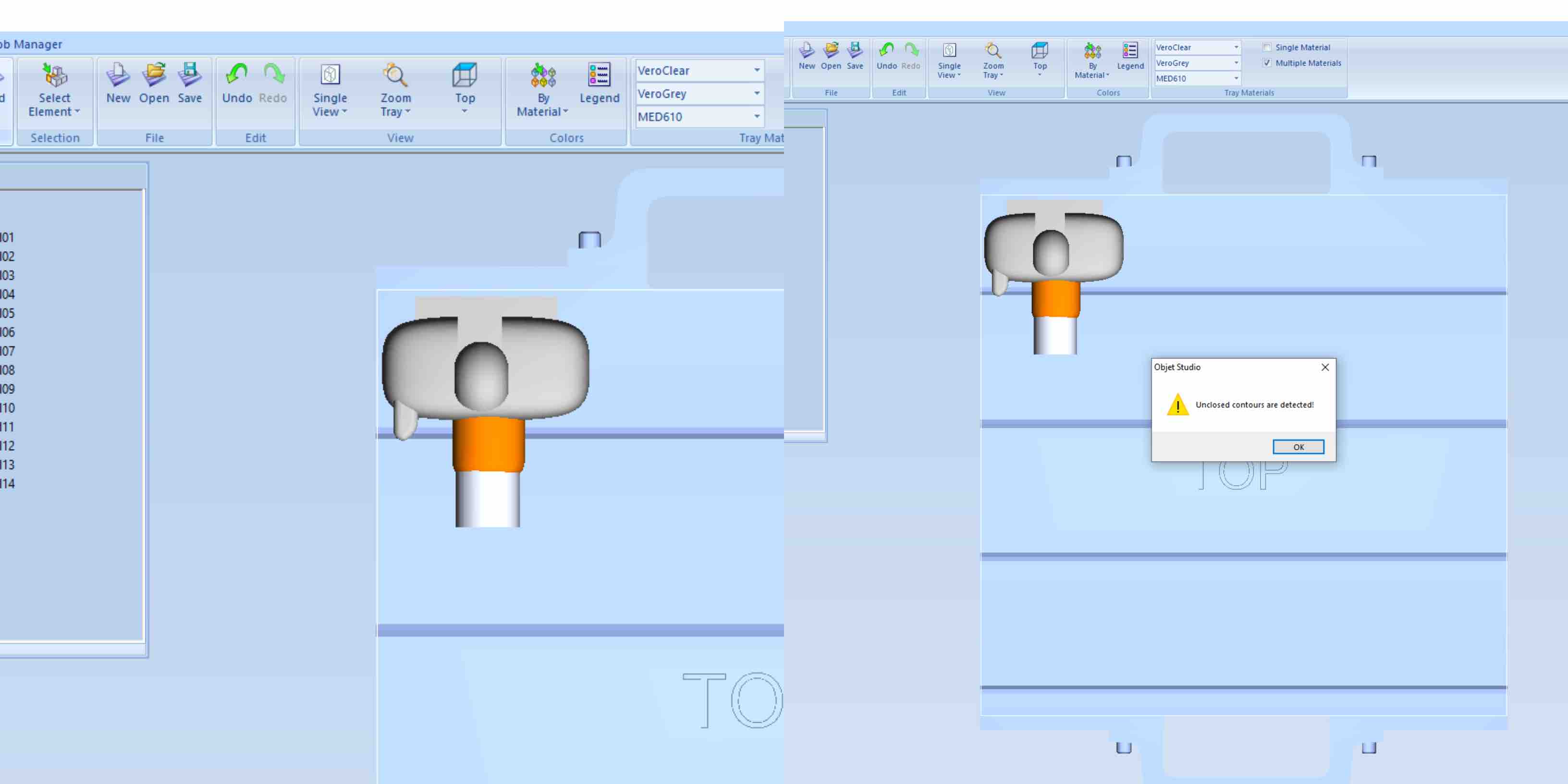
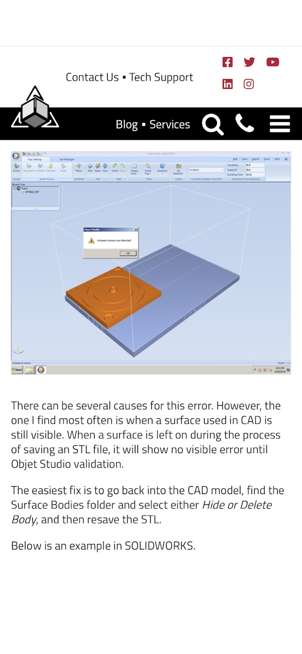
As I moved through the set up cycle it was now time to check my print integrity. However, it did not pass the check. It produced an orange color in place of the gray onto the form from the camera lens construction completed in Fusion 360. This also came with an Object Studio Warning stating that “unclosed contours are detected”. This was my first indication that there was an error in my model. I then researched the issue and found a possible solution. Following the steps listed I went back into Fusion 360 and deleted the form completely from the file. Leaving the lens looking more of a cylinder I saved the file and exported it again as an .stl.
After importing my new file the Objet Studio software approved my print and I was able to send it off to the printer. Using the same monitor, I flipped the switch on the switch box and transfered the computer to the printer interface. I was then able to select the red circle at the middle bottom of the options to begin the print.
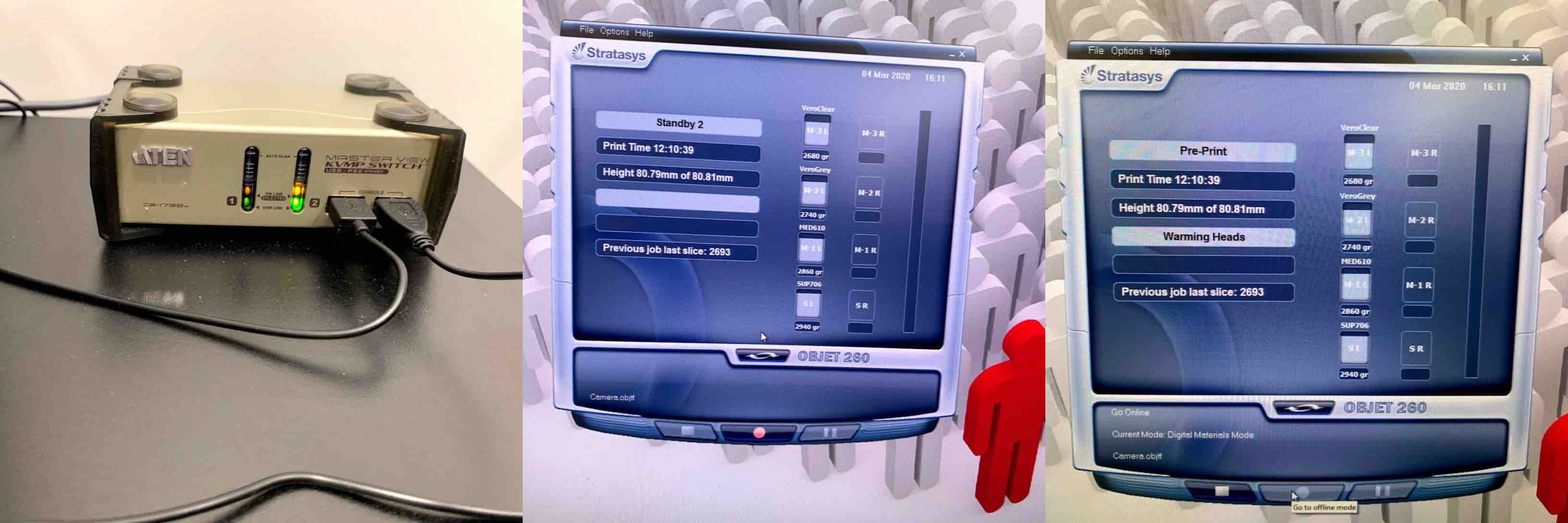
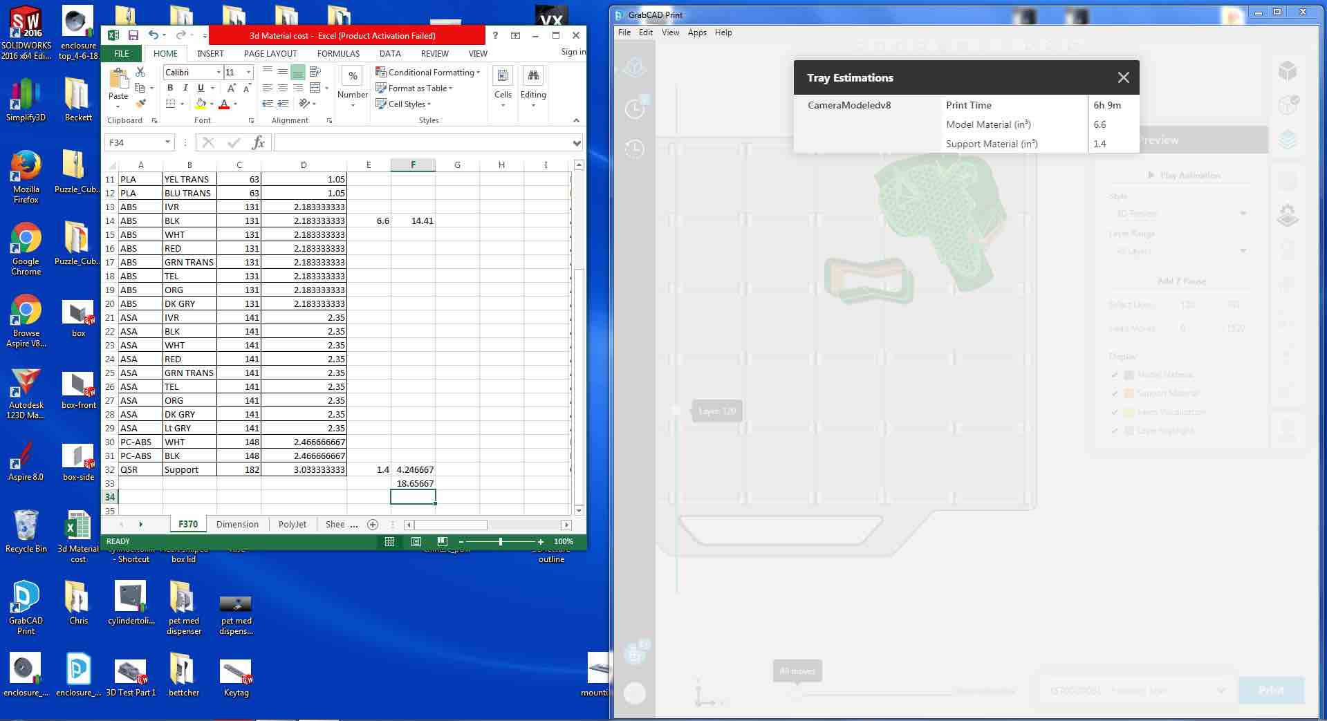
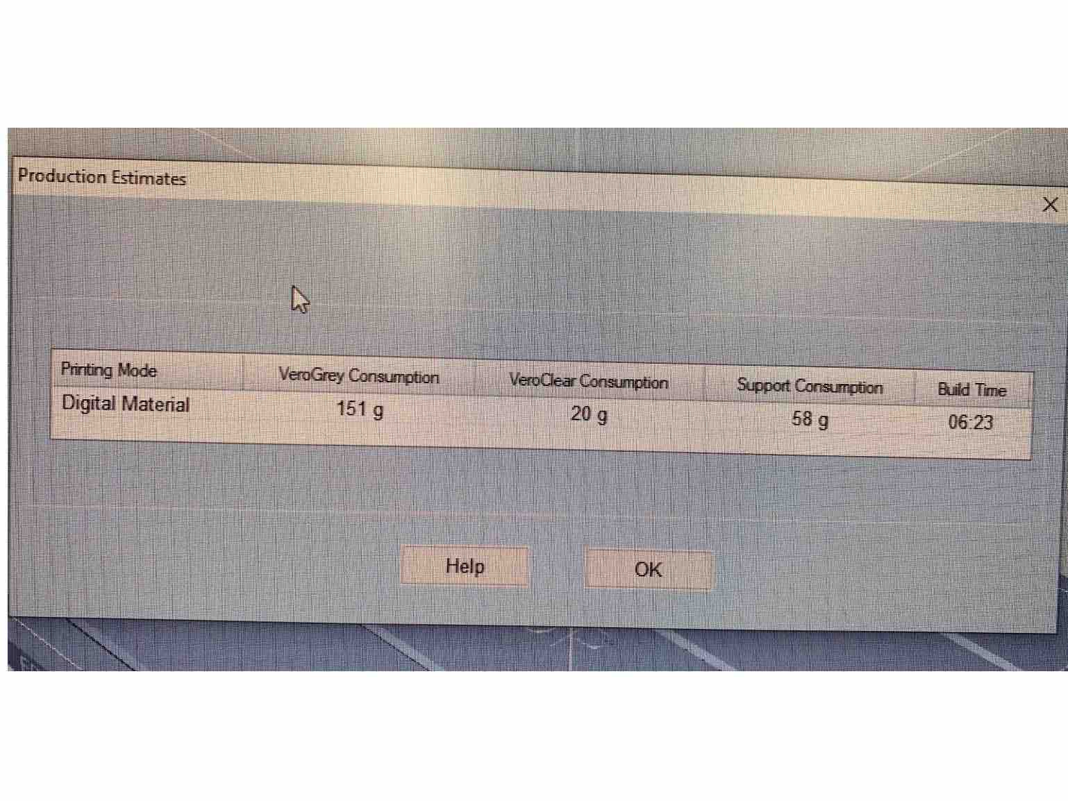
At the printer the Objet 260 warmed up and began slicing the layers to follow. Each layer is completed with both support material and modeling materials. The print was estimated to take over 6 hours. This machine can run without constant attention, however must be cleaned as close to the finish time as possible to reduce wear and tear on the machine and the print heads. If the liquid resin cures inside the print nozzle this can cause complication including but not limited to replacing the piece all together. This can cause the maintainer quite a bit of extra cost.
When the print is finished the front lid of the machine can be lifted to reveal the finished print. You will be able to see the clear gelatin support material and the gray build material.
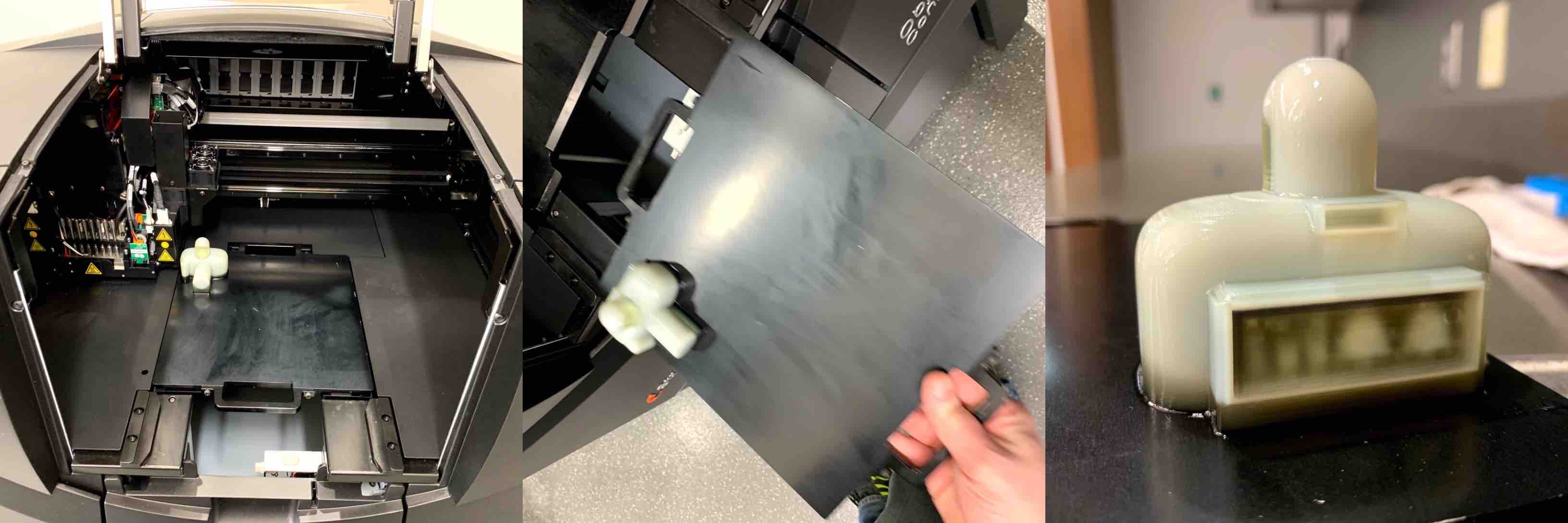
Objet 260 Printing
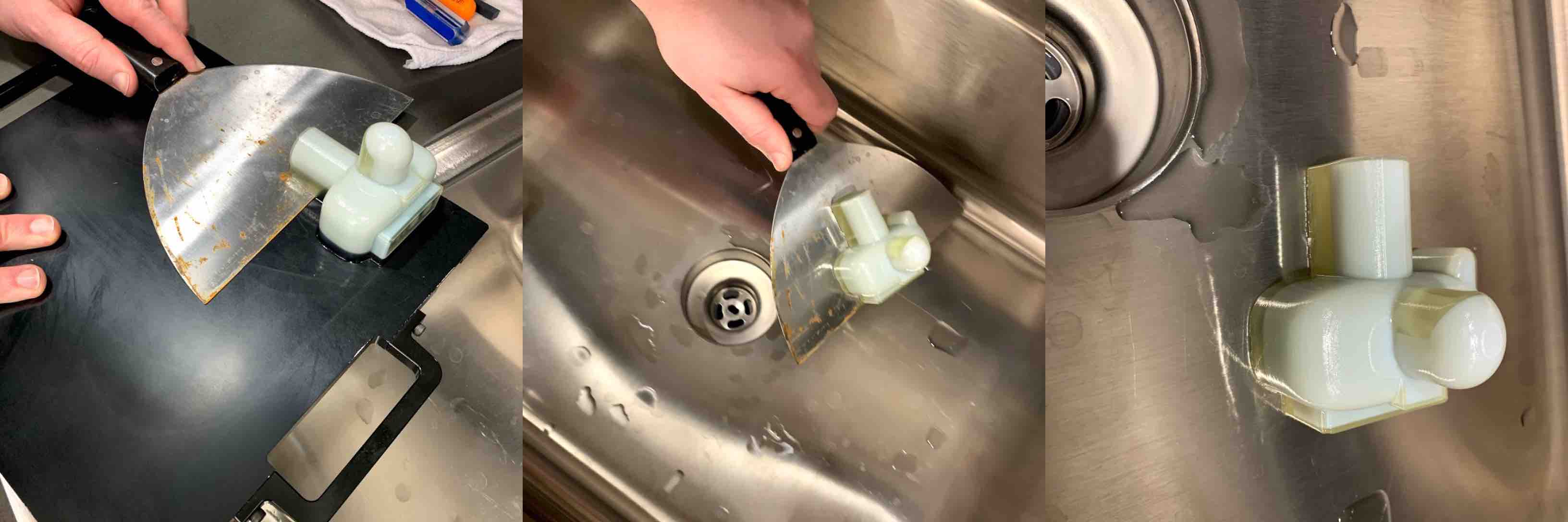
The gelatin support material will keep the part adhered to the print bed. To remove this a metal scrapper can be used to slide under and gently pull the piece off. This will leave behind a layer of residue that must also be removed, careful not to scratch the print bed. There is a smaller scraper provided to be sure there is a more delicate removal from the plate.
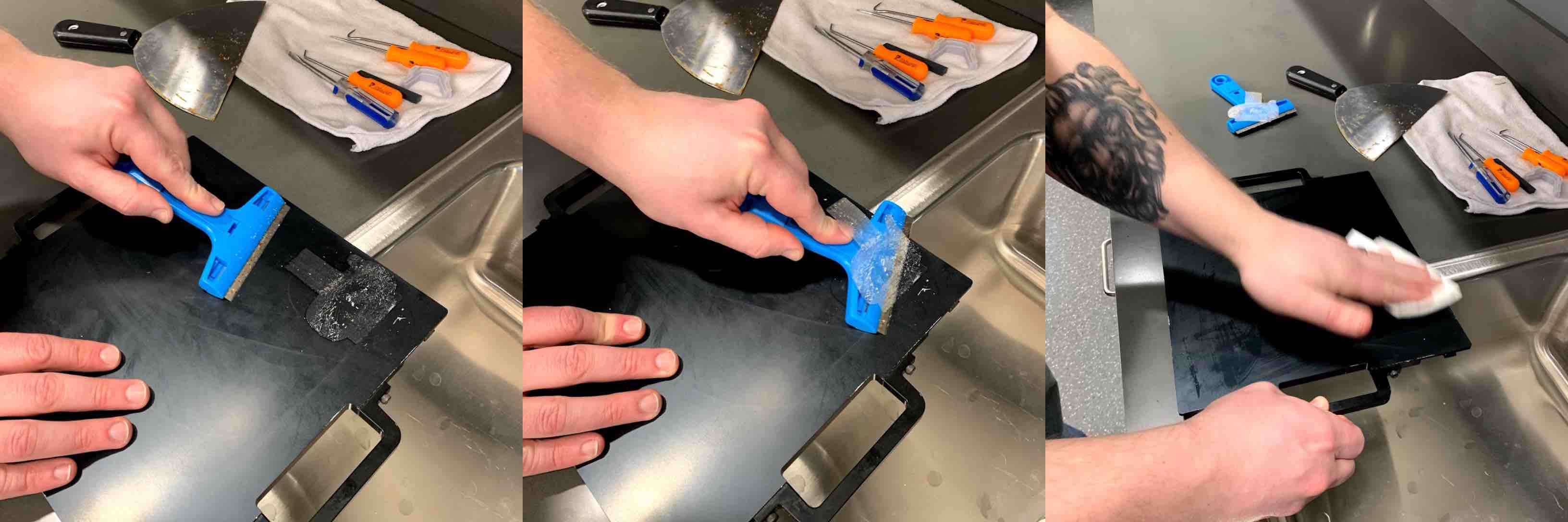
Once removed from the build tray the print can now be set into the sink to begin the support removal process. It helps the dissolving PH bath if you can remove most of the material before placing it inside. Once removing all pieces of support that break away easily the next step is to place the print into the PH bath to dissolve away the rest. The PH bath stays agitated to be sure that the support material inside rounded areas or hard to reach places is being dissolved completely. The hole in the top right corner of the clear view port representation was placed there to allow the agitated bath to reach into the box and dissolve the material holding the pieces inside. Once placing the piece into the tank, the agitator is turned on to begin the process. As the tank begins to move the bath around, it heats up and begins tracking the time in the machine. It is advised that most prints sit in the bath for 6-12 hours depending on the size of the print and the amount of support used.
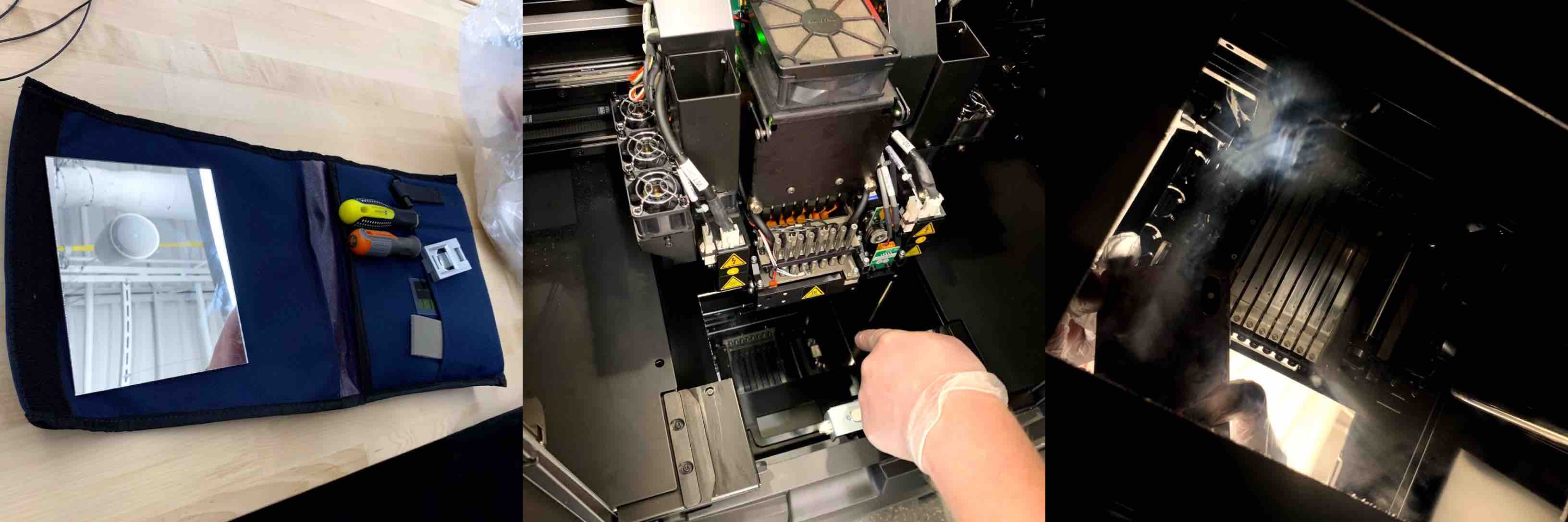
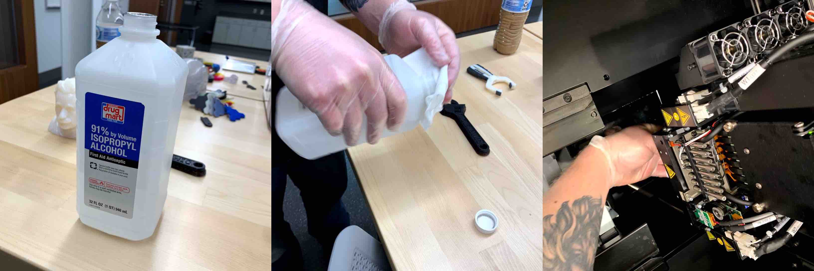
The next step is to clean the machine. Due to the liquid resin being cured with UV light the extruding nozzle can become clogged. To avoid this, cleaning the machine as soon as you remove your piece is advised. To clean the machine you must get the kit. When opening the kit there will be an array of tools, microfiber cloths, and a mirror. With the build plate removed the bottom of the machine is accessible. Placing the mirror in the bottom facing upward allows the nozzles to be visible. Using the microfiber cloth and adding a small amount of 91% isopropyl alcohol each nozzle should be wiped clean. The nozzles are visible with the use of the mirror. When the nozzles are clean the mirror can be removed, the clean bed can be placed back into the machine and the lid closed. This wraps up the cleaning process.
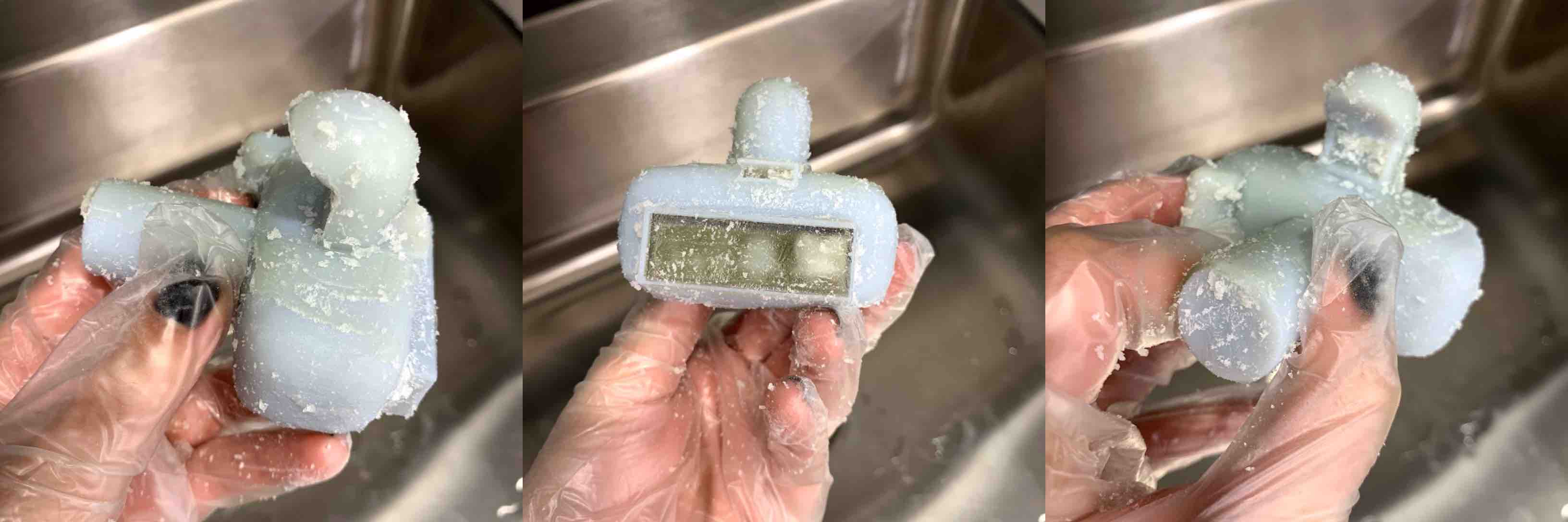
Once the machine is cleaned out and closed back up the last step is to wait for the print to finish dissolving support. Once this piece was removed from the bath it was clear that the support built within the clear box representing the view finder was not dissolving. After much consideration I decided that there were not enough of an opening to access that support material sufficiently.
Printing Model on Stratasys F370
When my Objet 260 model didn’t work I was very disappointed. I thought I understood how the machine worked but I realized I had pushed one of the limitations of the machine and it pushed back. At this point I decided I needed to step back, redesign, and change printers. I had a spark of an idea that kept the same concept but improved on the printing process.
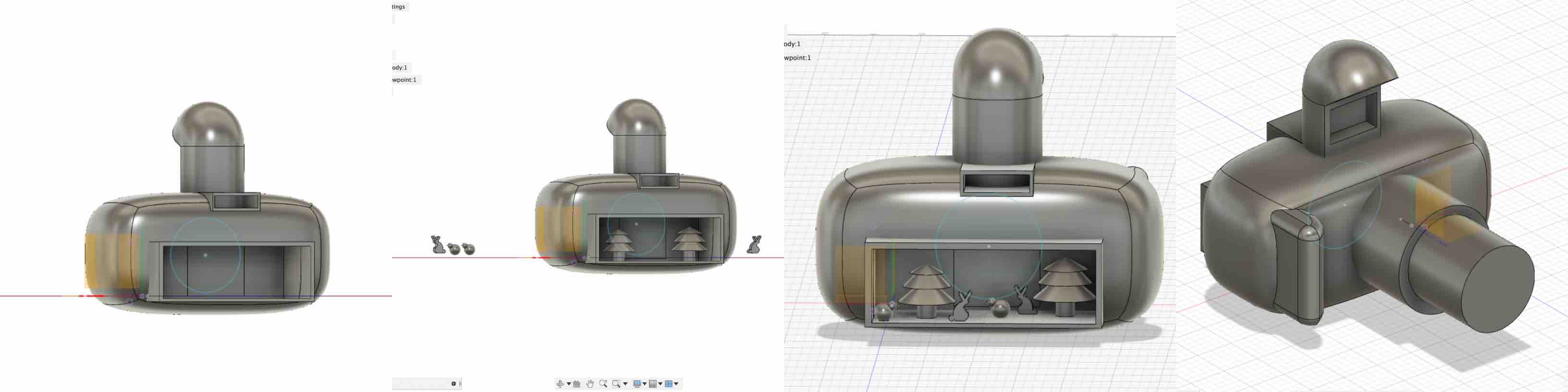
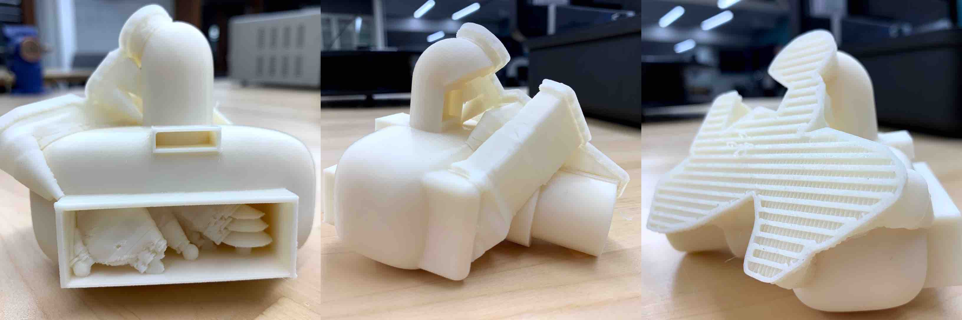
Keeping the original model of the camera I deleted the clear box. With this gone my new concept was to place the components within the view finder representation at different depths and anchor them to the bottom. The last change I made was to redesign the zoom representation of my camera. I wanted it to have a more realistic look. The changes will push the size and resolution limits, as well as the printers limits with support and modeling concepts. I believe this layout also meets the requirements of the assignment and could not be easily machined subtractively.
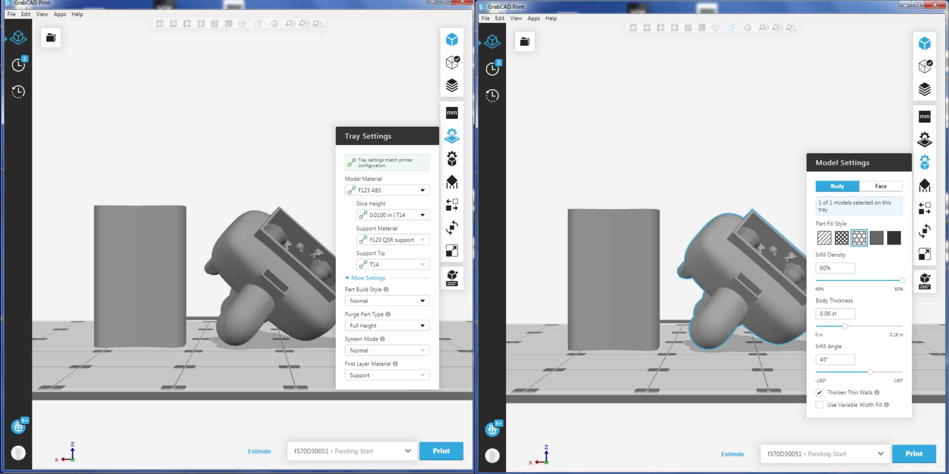
I imported my file into GrabCAD. GrabCAD is the Stratasys software used to communicate with the printer. In the software there is a tool bar on the far right hand side. This tool bar represents the steps needed to be complete before your print is ready to be sent to the printer. The fist step is to set the Tray settings. The tray settings are represented by a square thumbnail with a gear above it. In this window you set the modeling material, slice height, support material, support tip, purge part type and first layer material. I chose to start with a layer of support. This helps to give a stable base to build up from. I chose for this print to use a purge tower in a bow tie shape (explained in section on advantages). You also assign materials in this window. The next step is to determine the model settings. These settings allow you to choose face and body settings. The face settings stayed at the default settings. However, I did choose the body settings. I chose the hexagonal part fill style. This was suggested to both save material and keep integrity. I changed the infill density from the default setting of 60% to a 46%. I was also able to set the body thickness and infill angle. The last option I chose was to thicken any thin walls. I chose this option as a fail safe for parts of the model that may have been modeled weak.
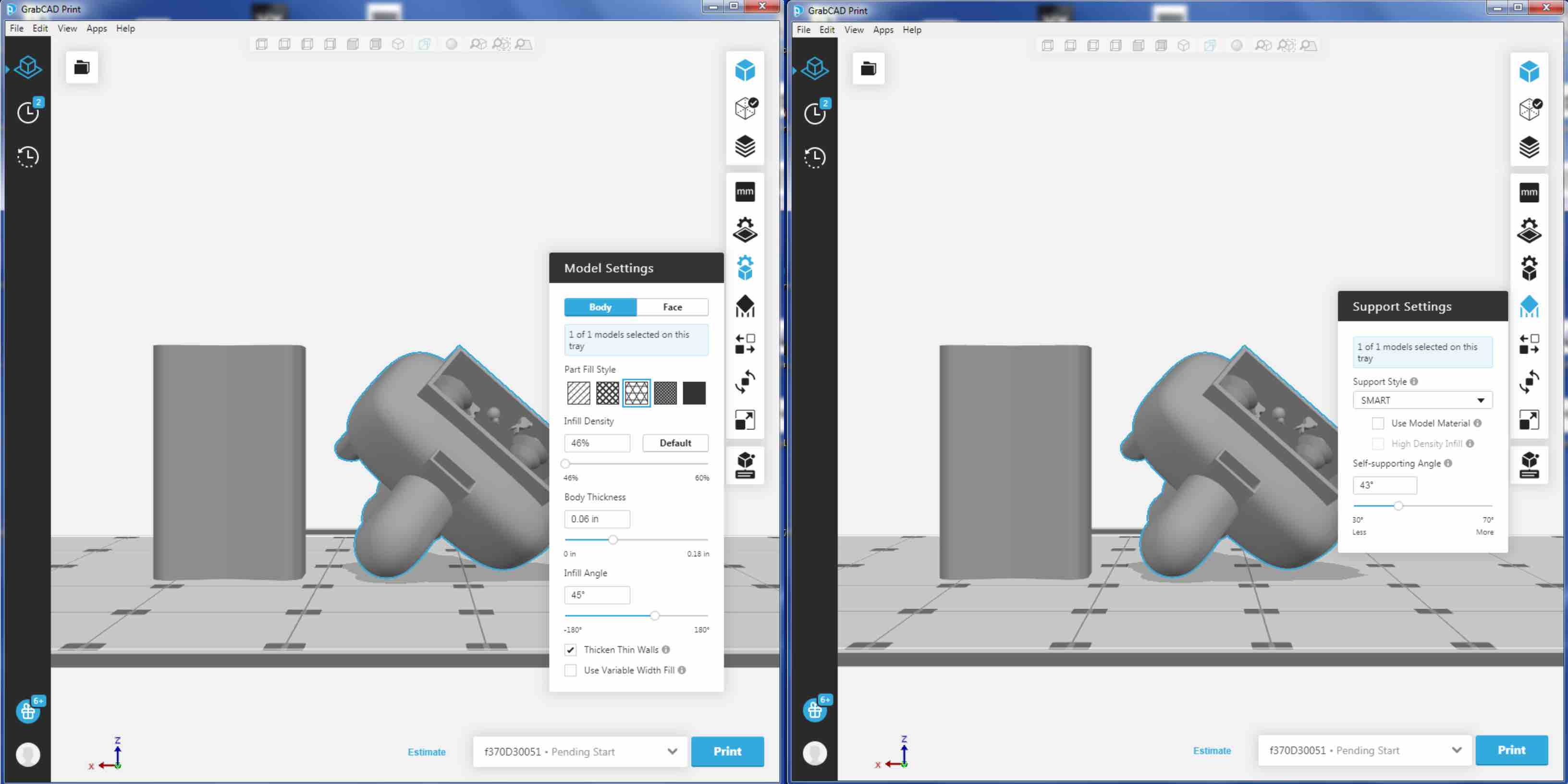
The next setting included setting the support. I chose SMART Support Style. This automatically filled in the model as the software saw fit. In the end this turned out really well.
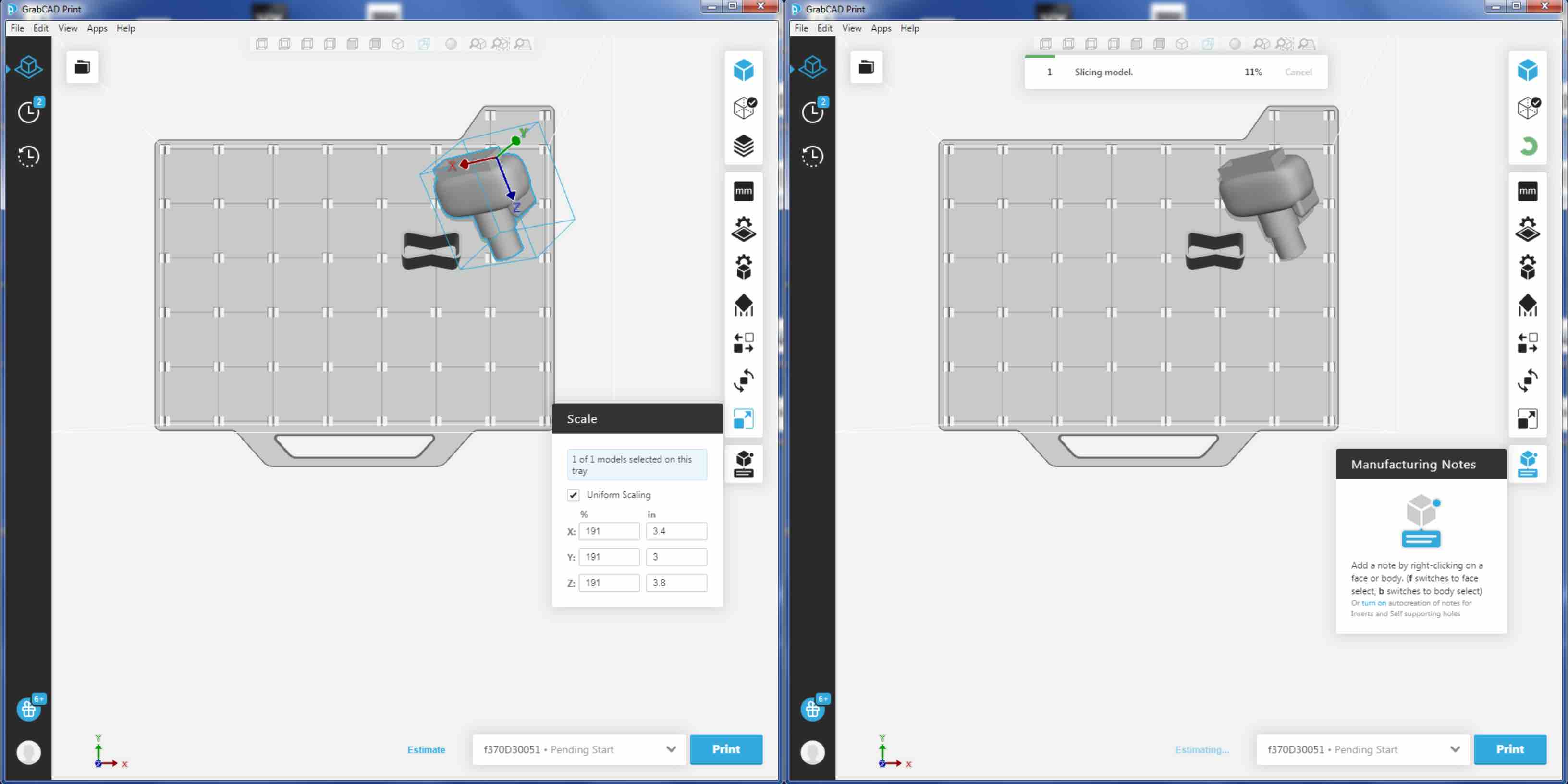
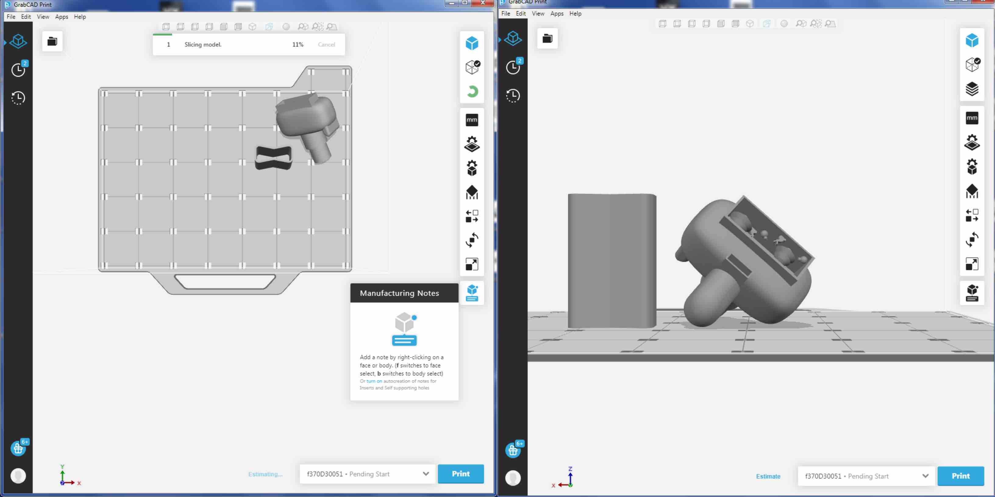
Orienting and scaling the model was the next step in the process. The orient settings allow you to move the model to a location of your choosing. This can be helpful to make the most use of the tray that you can. The tray in the Stratasys F370 was not made to be reused consistently. It can be reused for a short time but will have to be replaced. By arranging your model in the area you choose you can place it somewhere on the plate that is clean and not been previously used. The Auto Orient option orients your model in the best layout to be printed. When chosen it turned my model on its side and set it at an angle. This was an odd way to print for me so I was really shocked at first. I decided to trust the software and test the printers limitations. The scale setting allows you to adjust the size of the model. This can be uniformly scale or scale the model nonuniform. This means you can adjust the size on the X, Y and Z axis’ as a one or independently. It also provides a percentage option or a measurement option. This is a nice addition because you can make certain parts all across the model the exact size you want.
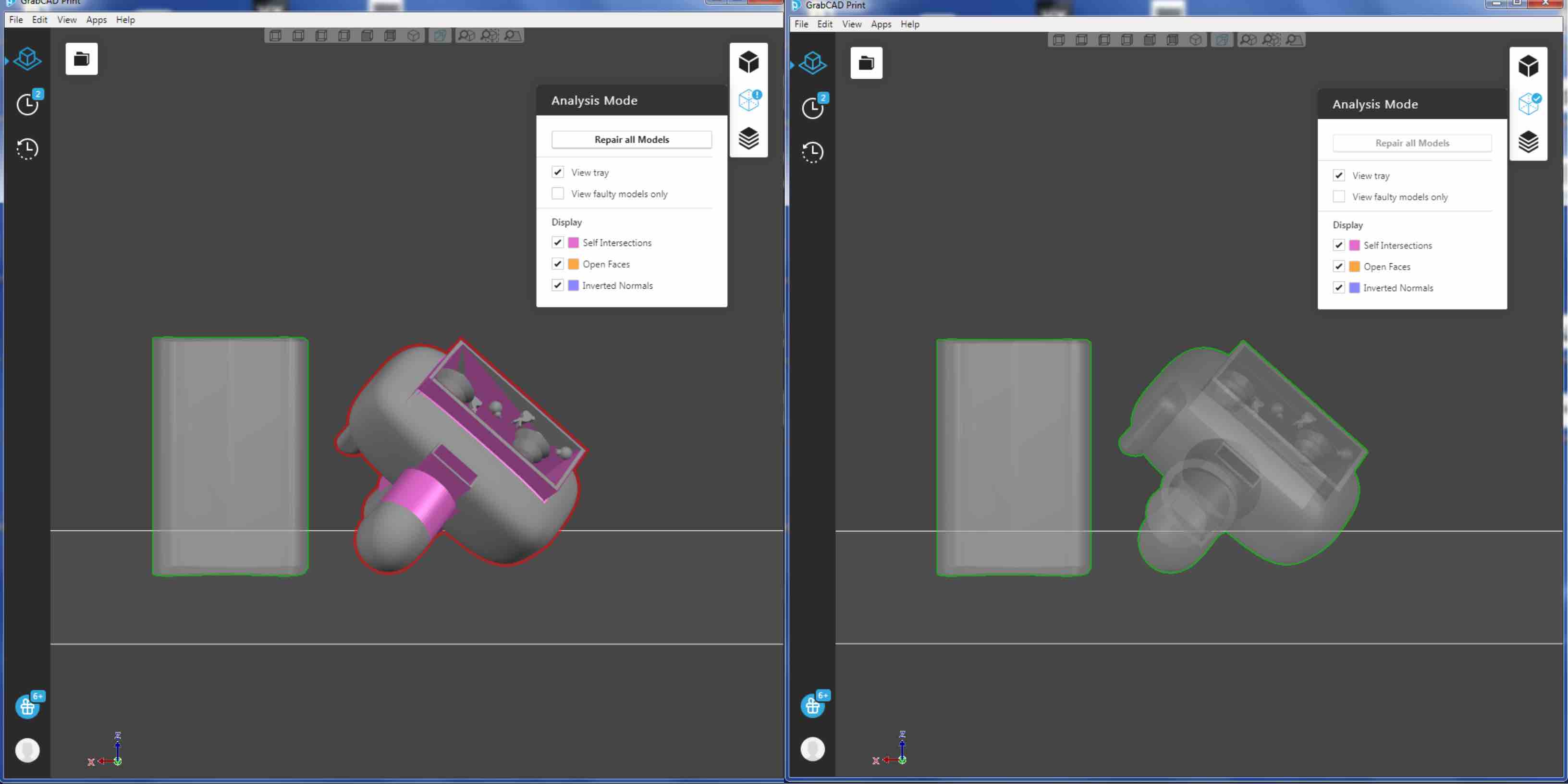
The next step in the process is to check the print for validity. This means to run the check system in the software to be sure that the print has no issues. Upon the first run it showed some purple shaded areas on on the gray model I had been working with. This indicated that there were Self Intersections. There is an option to Repair all model. This is another advantage to the GrabCAD interface.
The next step is to check the print layer by layer in the slicing window. This allows you to see how the printer plans to build the model and where it chooses to use each material. This can enlighten you to how the machine will lay out each layer, as well as showing you where there might be issues. This will also allow you to fix your model one last time to ensure a success in the print.
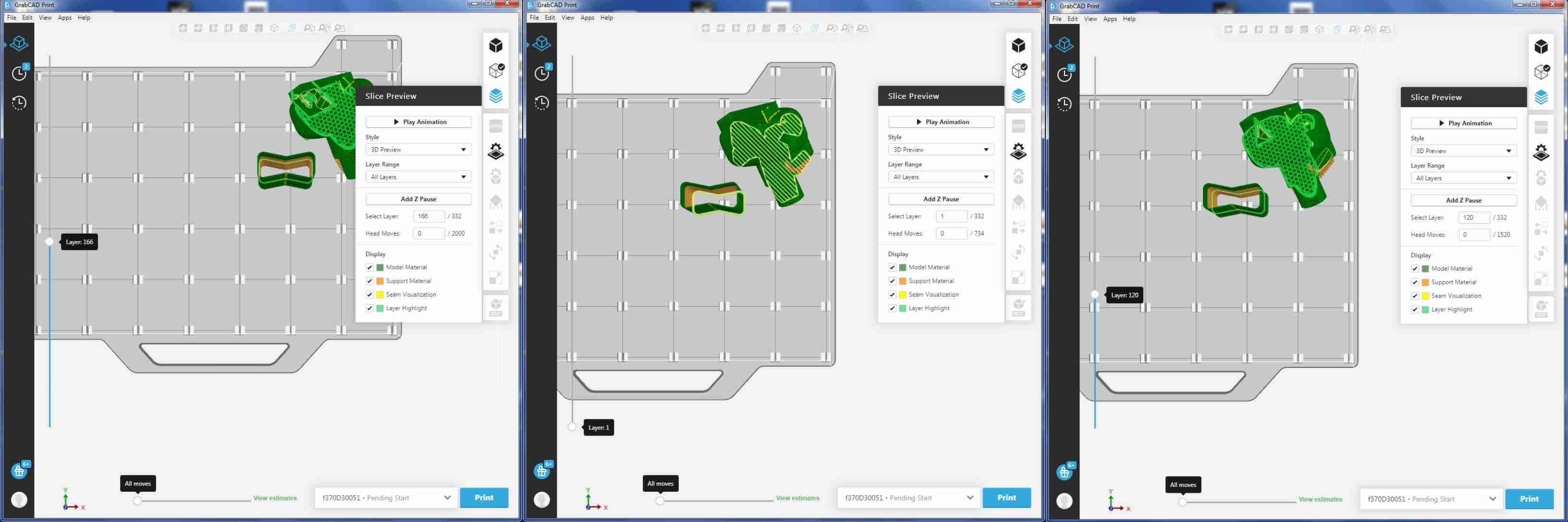
The last step is to check the model overall to be as accurate as possible. This is the last step in the process before sending the model to the printer. Since the model was fixed to fit the printer it was time to push everything through. I sent my model to the printer and began the next process.
As an additional practice I used a spreadsheet on our desktop to calculate the cost of printing a model this size. This is considered a cost analysis. This is then added to technician time and design time as well. This is important to understand how to calculate when moving from a hobby to a profession, and even when keeping track of personal material use vs. future costs.
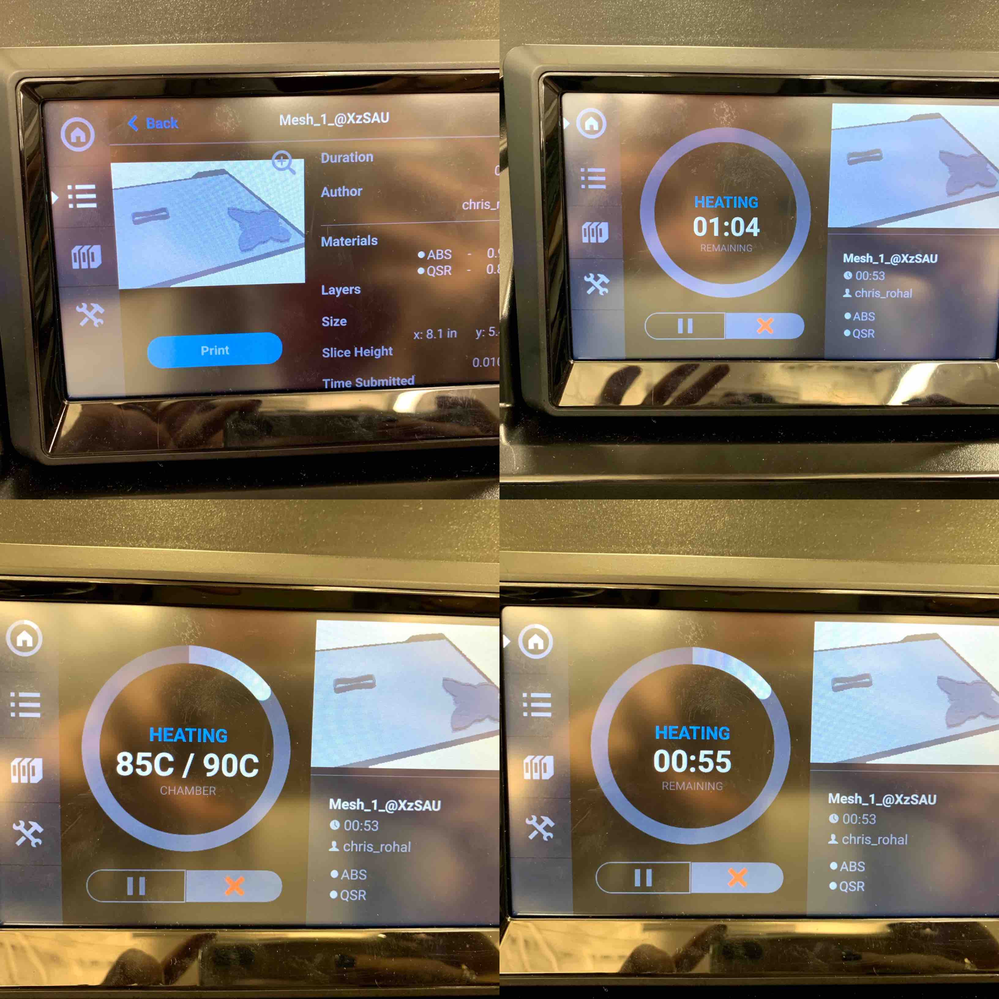
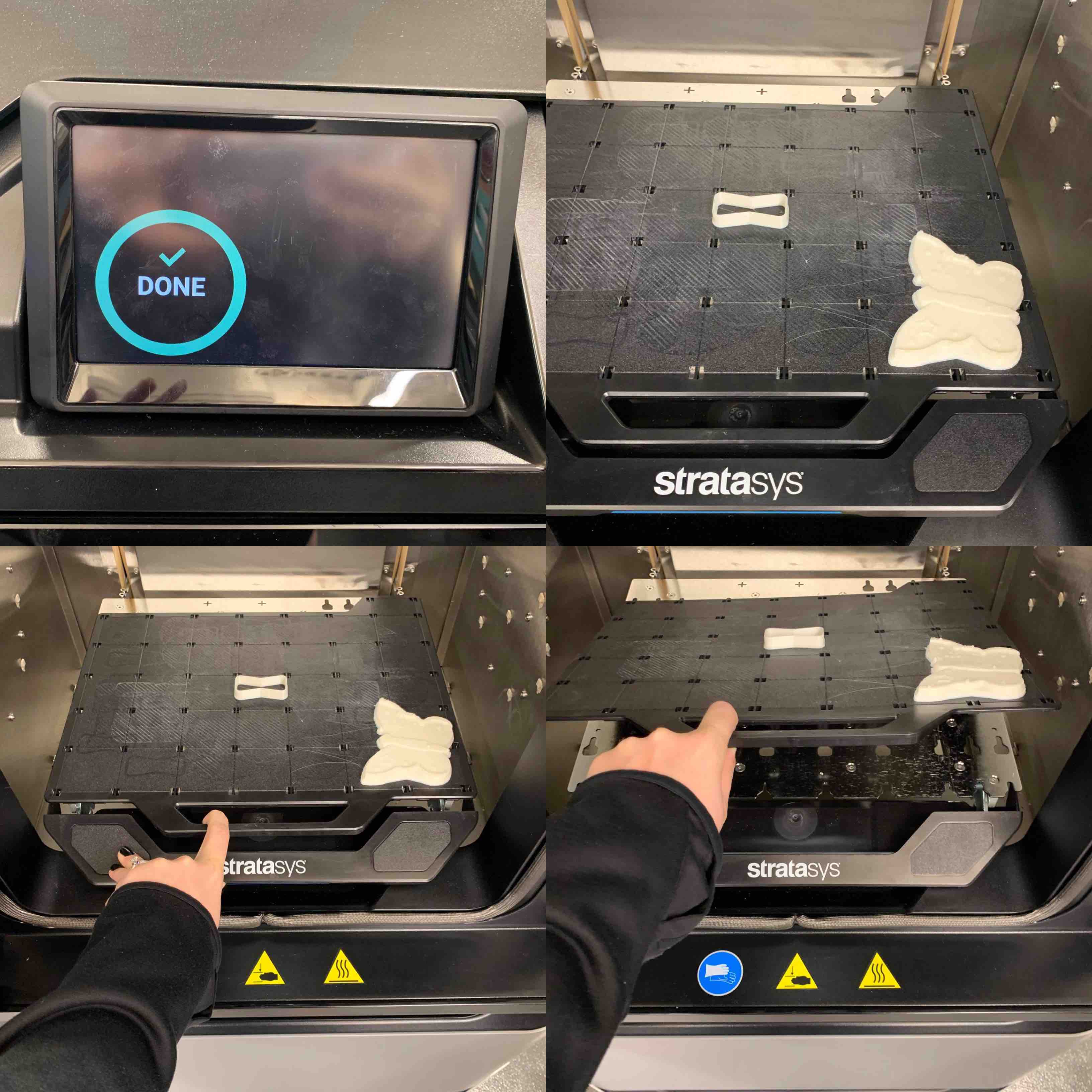
Once GrabCAD sends my model to the printer it begins the print cycle. Going over to the Stratasys I interacted with the screen located above the build window. This display will show you all the details of the print including but not limited to the time it will take to complete, the materials being uses and will even show you the placement on the plate. Once all information is reviewed and the model looks good you can choose the print selection and being the actual printing stage.
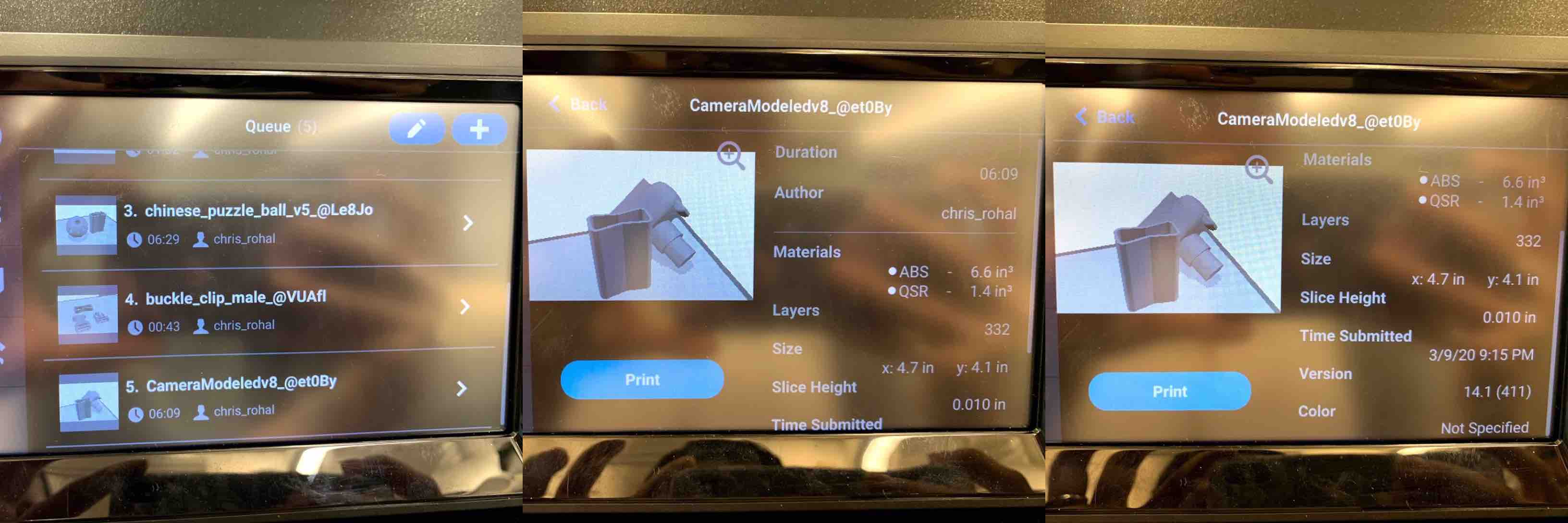
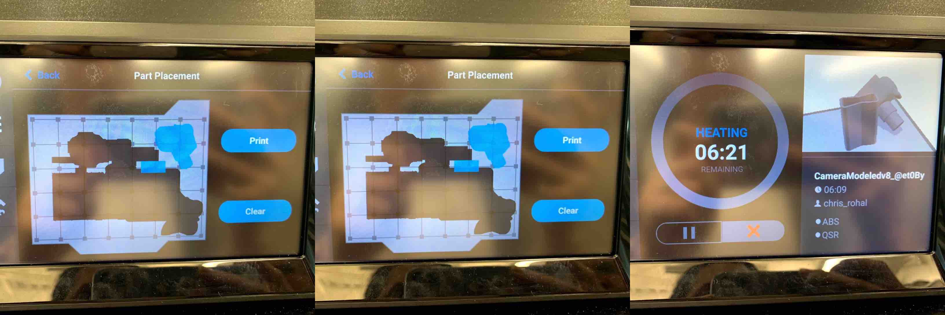
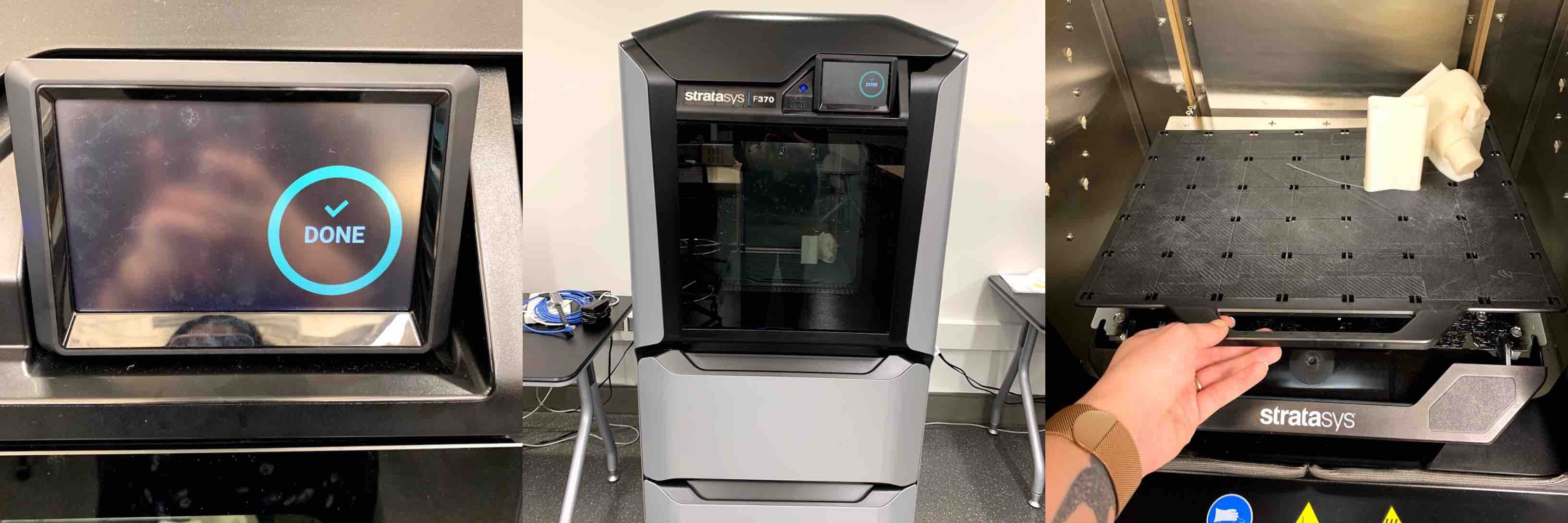
The print was estimated to take over 6 hours. At this time I left the printer to do its work. Based on the time I started the print I had to return the next day to remove it from the printer. Coming back the next morning the print was finished and the display informed me it was Done. I opened the door to the printer and found my finished print. I pushed down on the leaver in the front of the build plate and lifted to remove it from the printer.
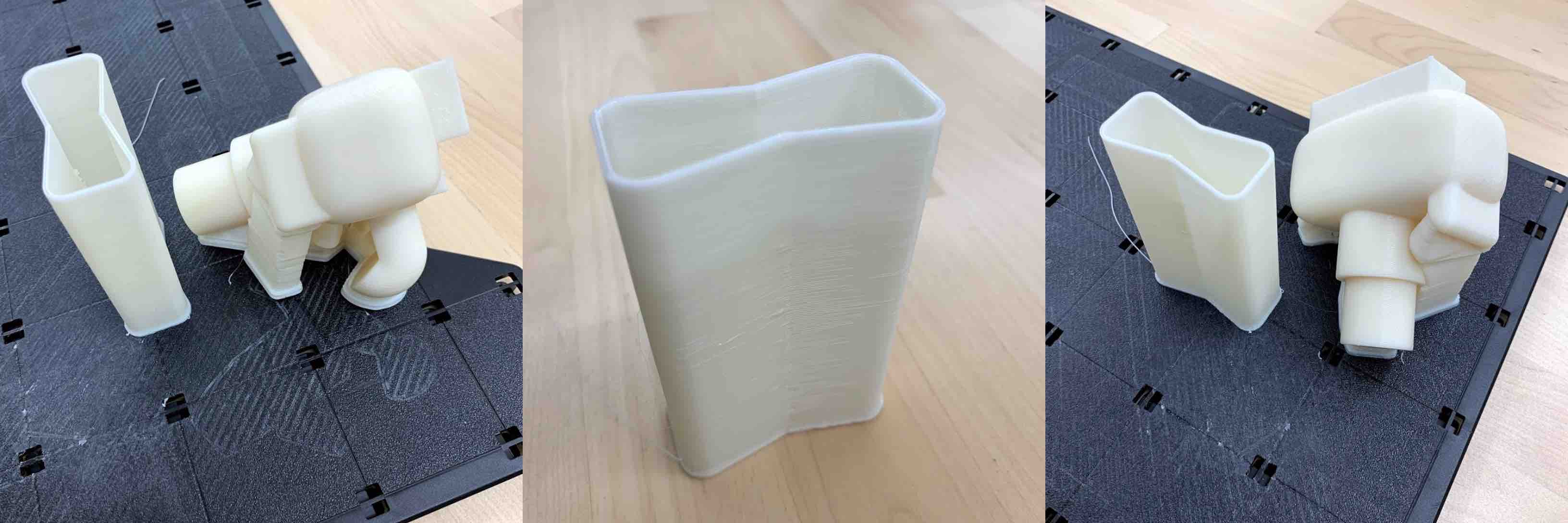
Once the tray was pulled from the printer I could see the print better. I could see how the support material was layered around not only the outside of the print but the inside the view finder representation where my smaller components were located as well. This gave me hope that the print might work. Next to my print was the purge tower. I bent the build tray slightly and was able to pop my print from the surface, as well as the purge tower. I then was able to examine it closer. I was able to see the support material pattern as it was layered from the bottom up. I also noticed the angled way that it printed was actually very precise. The print went as planned. I was overall please with how my print looked.
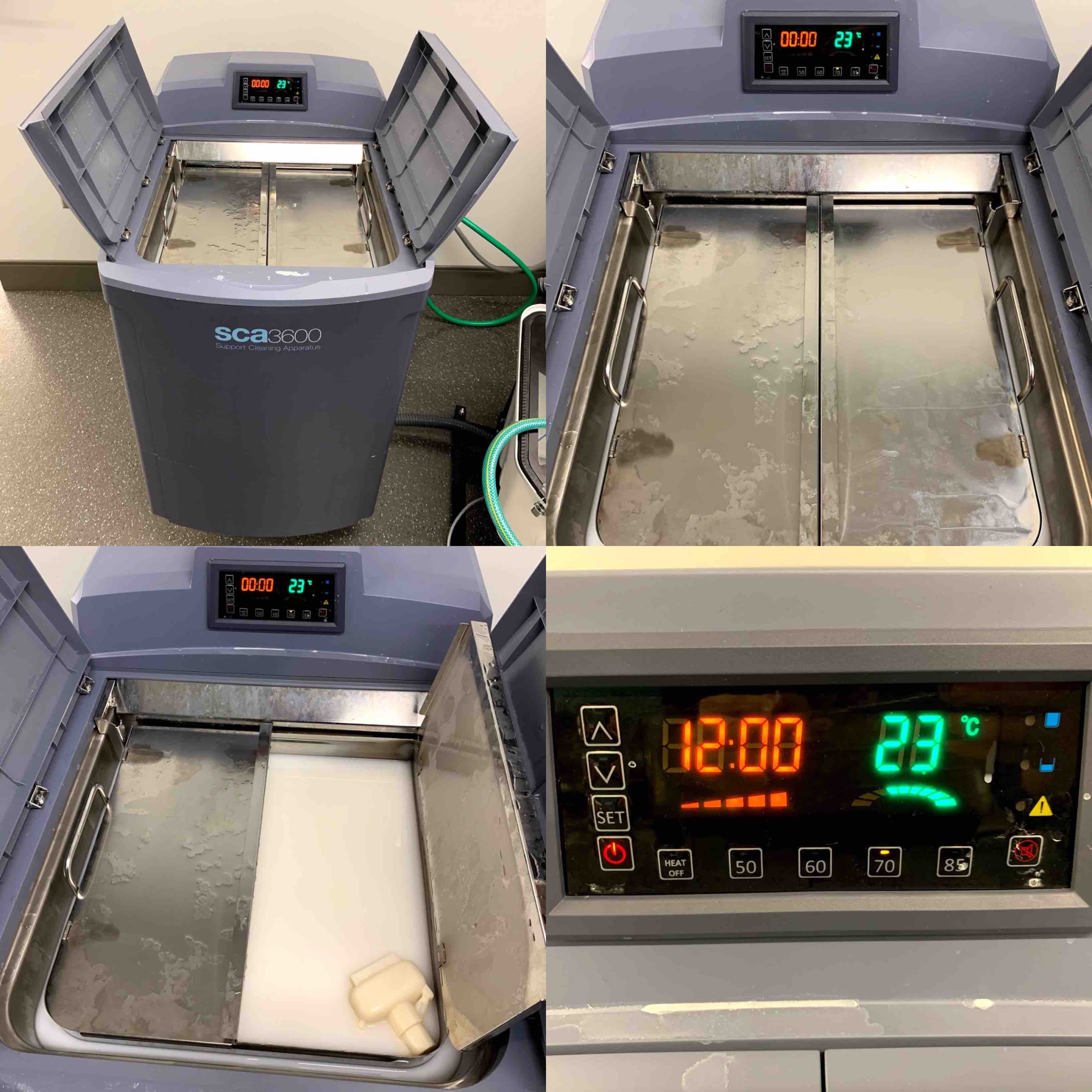
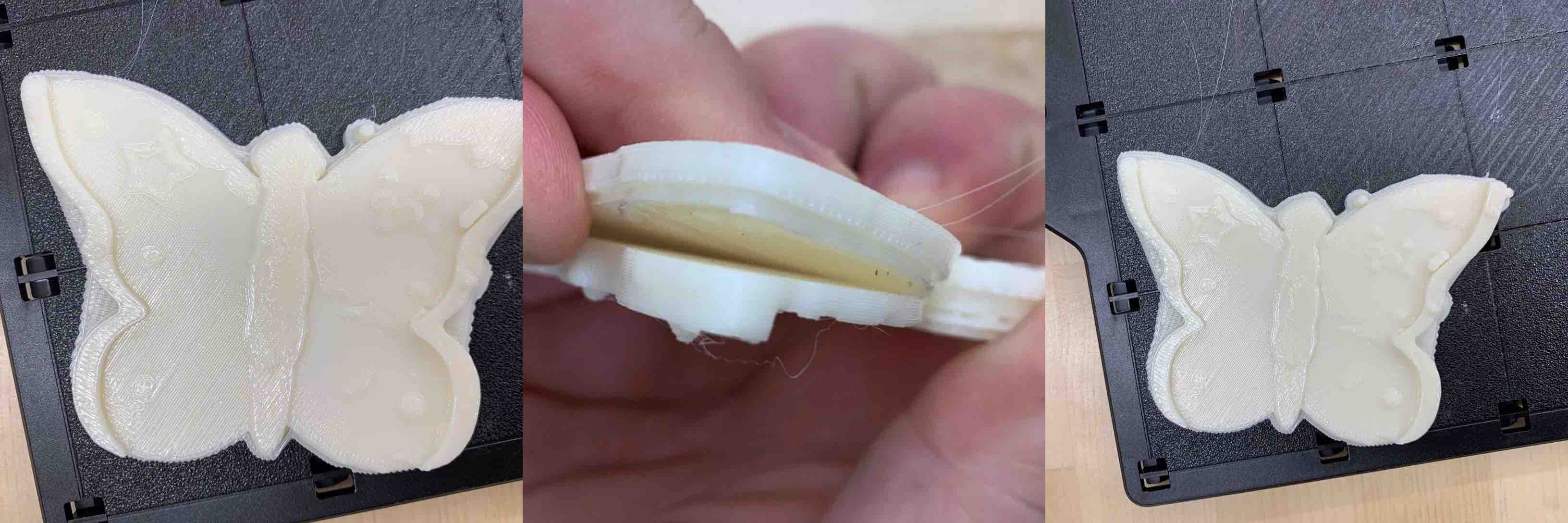
The last step was to let the support material dissolve in the PH Bath made from diluted Sodium Hydroxide. I opened the outside lid and it revealed the metal tank inside. I dropped my model down into the opaque mixture and closed the doors back up. I set the clock to run up to 12 hours and let it being to heat up. As it heated up the tank the liquid began to agitate. The movement allowed the PH bath to move and dissolve the support material more efficiently.
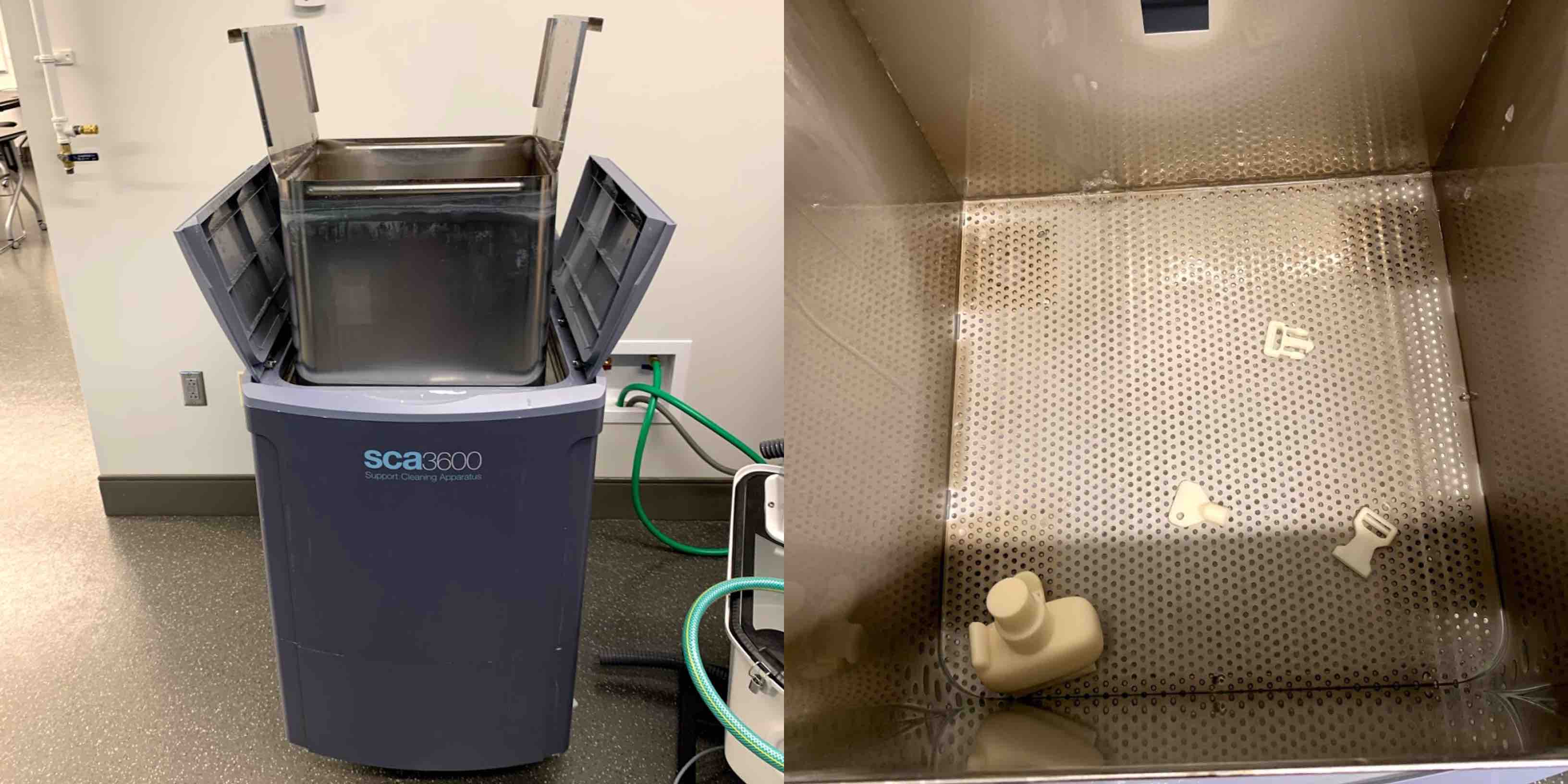
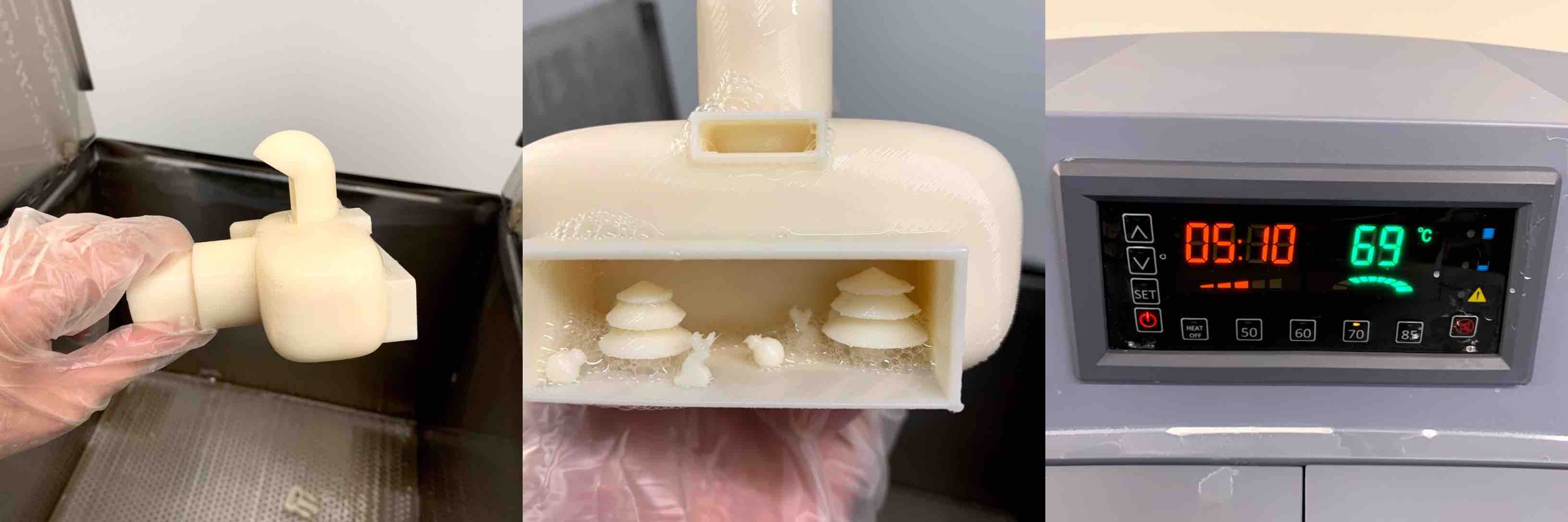
After 9 hours I decided to check on the progress of my piece. I removed it from the tank by opening the doors to the outside cover of the machine. This allowed me to use the handles on the metal tank to lift it from the liquid. There are pegs and a ledge that the tank balances on and holes in the bottom for the PH bath to drain as it is being removed. When the liquid is drained I was able to remove my model. I took it directly to the sink and was sure to thoroughly rinse my print with water. This was to remove any lasting chemicals and ensure the print integrity. After the rinse was complete I was very thrilled when it turned out how I had imagined.
Hero Shots
Progression Shots
3D Scanning
3D scanning is a technique used in the industrial world to create a specific replication of a piece or part. This can then be used to mass produce what is needed.
To being with a 3D scan you have to decide which one to use. Our lab has two options the work the best and an archive of another process.
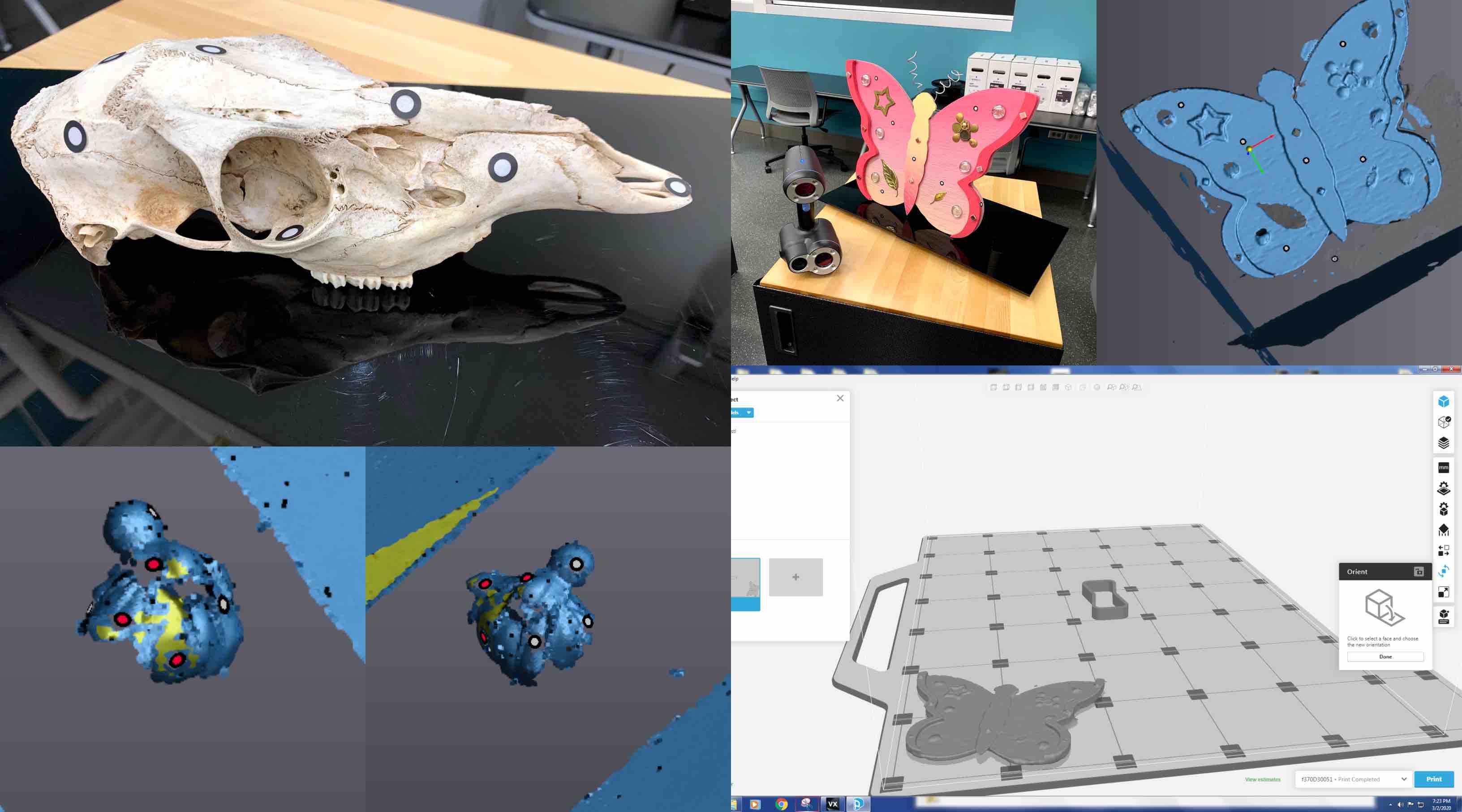
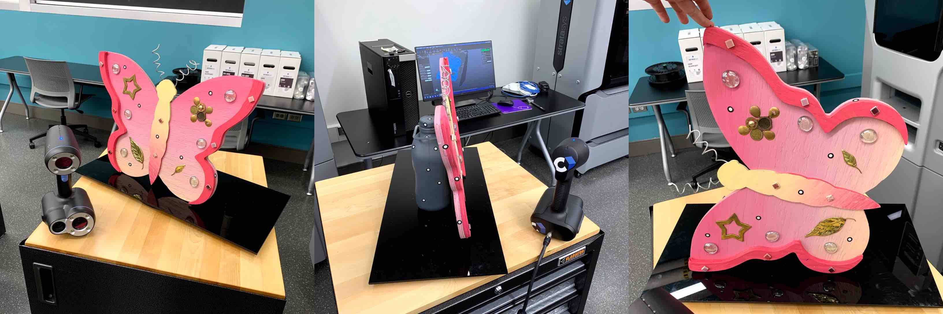
The scanner I chose to use was the Creaform. This is a 3D scanner meant to scan large objects in detail. The rule of thumb is to scan something larger then your head. There is a system of adhesive dots added to the object being scanned that assists the scanner to pick up the organic shapes. If the scanner is still having complications there can be a layer of matte gray spray paint, or a powder, that can be added to your piece/part. This will help the scanner to pick up the different surfaces in better detail. Some pieces are harder to scan than others. Keeping in mind that the part scans better if it is a matte color, a neutral color, contain the adhesive dots and has surfaces easily reached by the emitted lights of the scanner.
To use the Creaform there are a few steps you must complete.
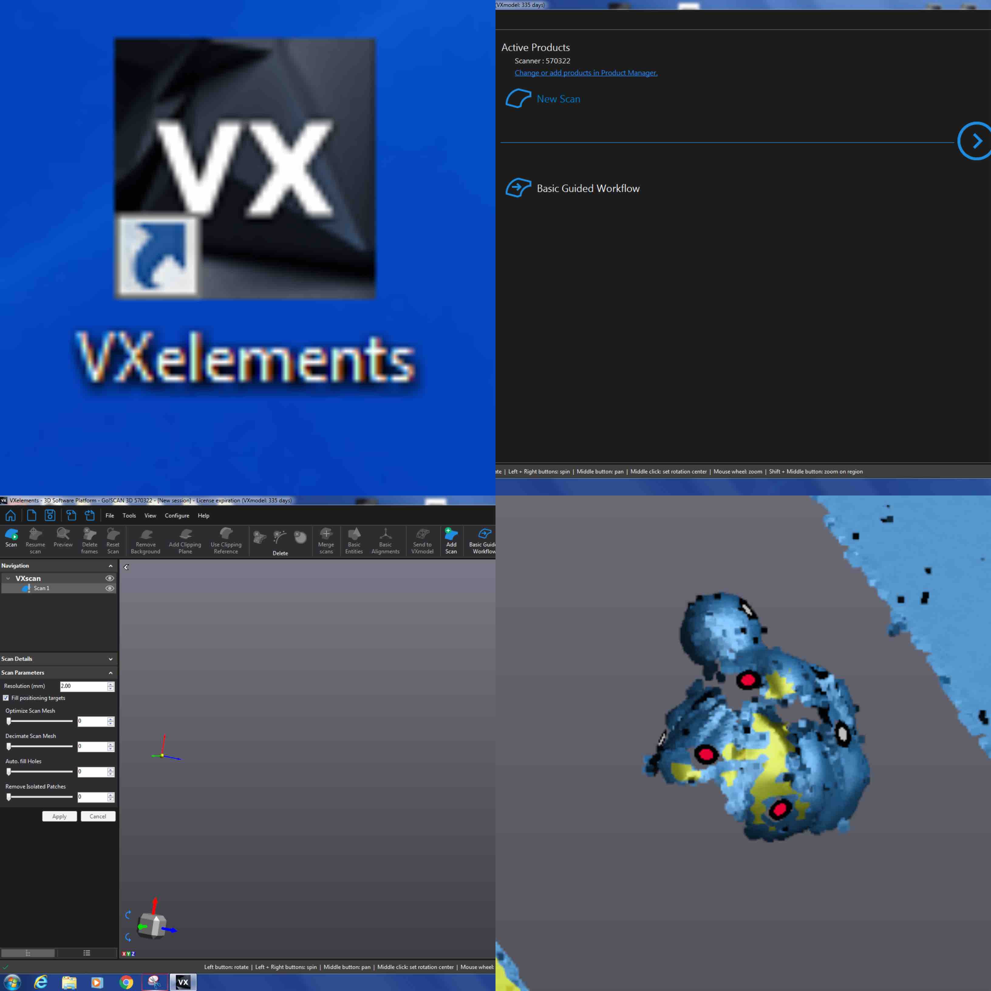
- Located in the Desktop is a black thumbnail with the letters VX in white. This is for the software we use with the scanner called VXelements. Double click this thumbnail and it will bring you to the main screen of the software.
- This main screen is where you want to select New Scan and press the blue arrow to continue.
- Once you begin a new scan it will pull up a workstation. This will have an array of tools across the top tool bar and the left side of the screen. With your model placed onto the black acrylic base and the adhesive dots in place you can select the play scan button on the top left.
- This will allow you to use the trigger in the scanner and being the scanning process.
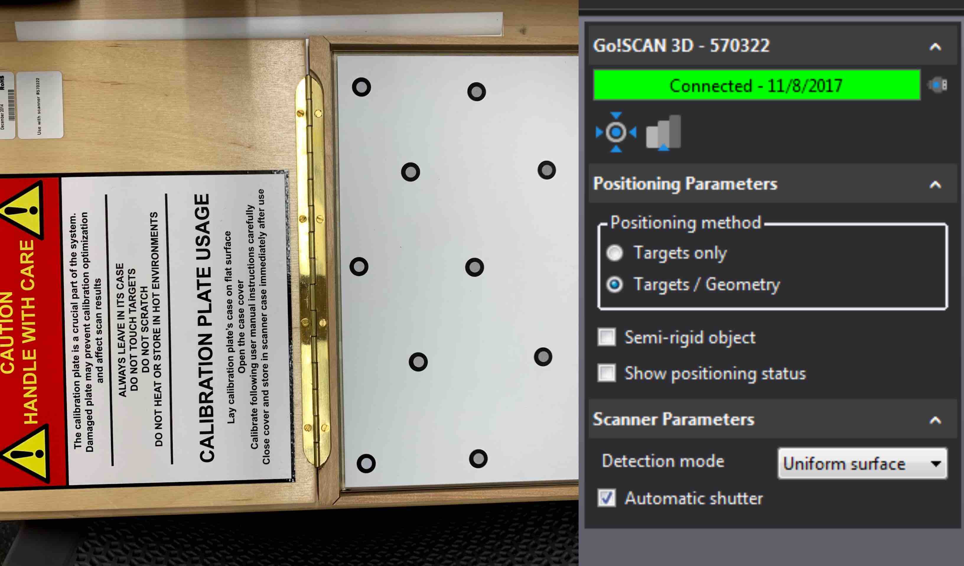
- Keep in mind there is a calibration process that can be completed using the calibration plate (in the scanner case there is a white plate with adhesive dots) if the scanner needs it. This would be needed when the scanner isn’t working correctly and if you change locations or lighting. The other Thing to keep in mind is that before you begin scanning you can set the scanner to read both Uniform Surfaces and the adhesive dots. When Detection Mode is set to automatic the scanner will adjust to the best scan of the surface.
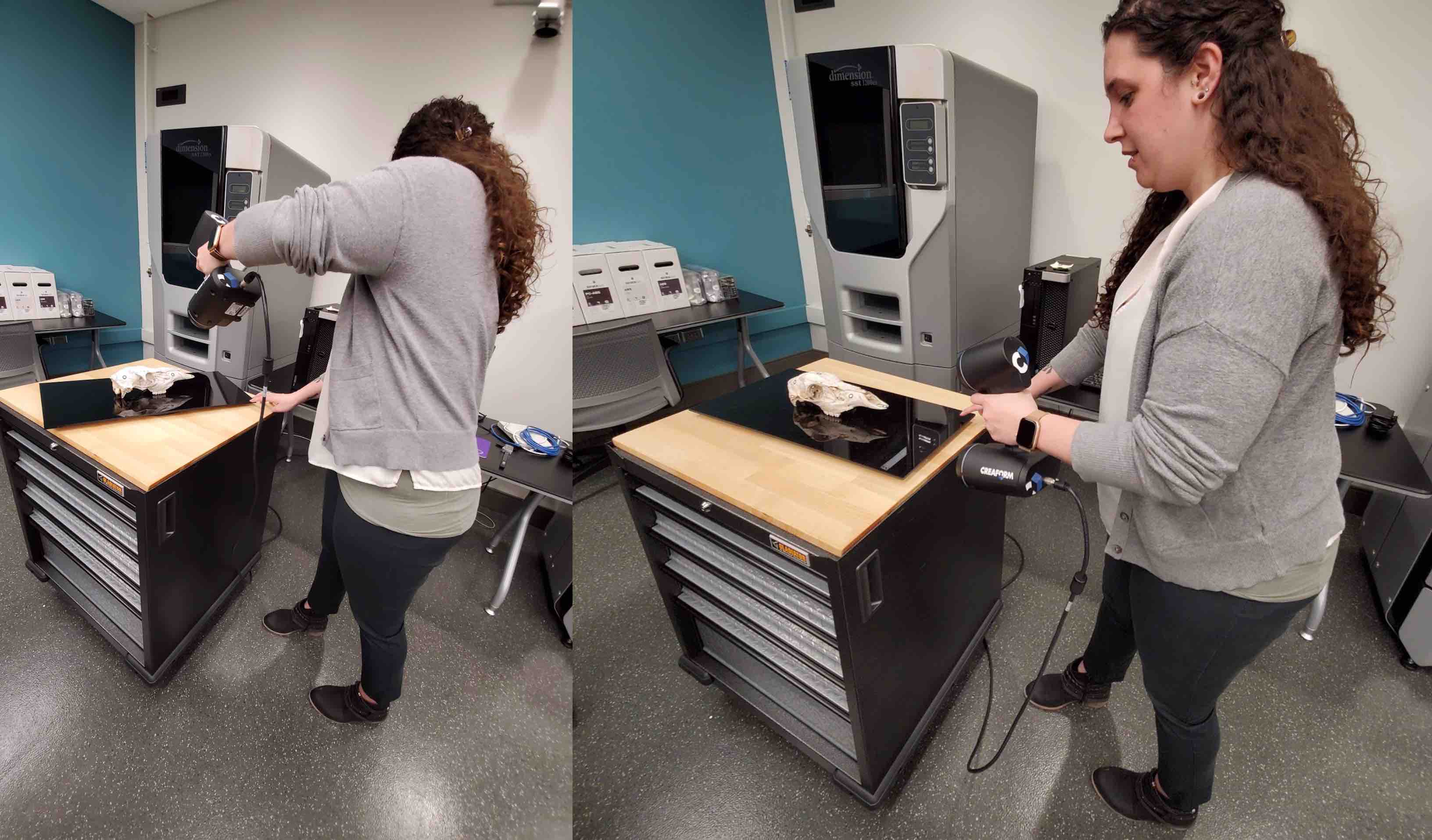
To being the scanning process you need to be sure that you have applied the adhesive dots in random order. The scanner uses the 3 adhesive dots at a time to triangulate where it is and help in the scanning. You also need to be sure your model is placed on the black acrylic stand. This will help to cut out background noise. When you are scanning the Creaform fits into your hand and there is a trigger located under the light system. When pulled in, this trigger activates the scanner.
The scanner has 3 lights located in the top. The front light will flash red if you are too close and the back light will flash red when you are too far away. When the middle light flashed green you know you are picking up the scan. Being sure to keep the correct distance from the model, rotate all the way around the model and scan the top. You can then tilt it on its side, starting with a location of dots the scanner has previously recognized you can then scan the bottom.
When you are satisfied with the scan of the model you have created you can move on to using the software again. The VXelements software provides you will mesh clipping options. I used these options to clean up my scan.
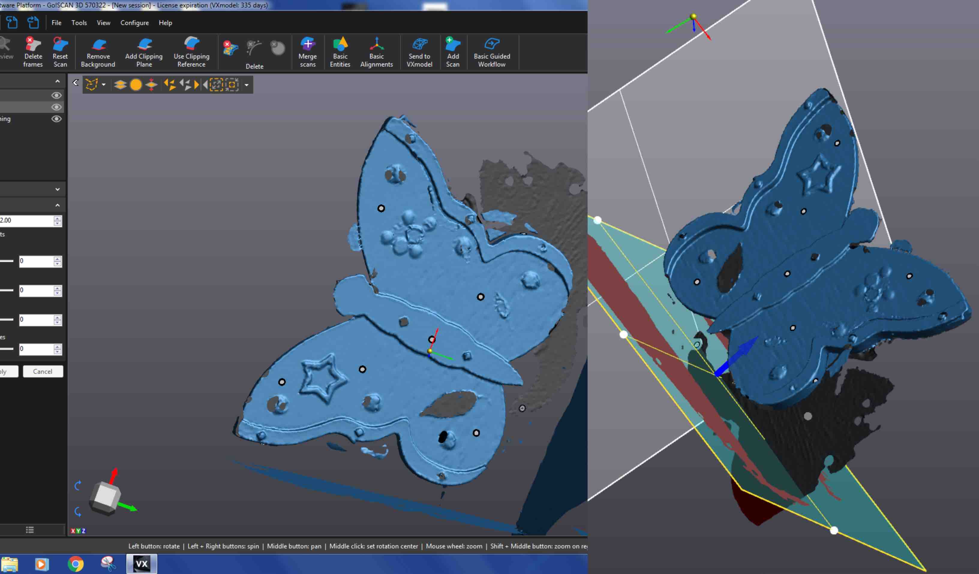
- I used the Remove Background option in the top toolbar to set different background locations. I aligned my background representation with both side, the top and the bottom of the finished scan. Anything beyond that would preview in red and then be deleted. This helped to delete all the excess noise in the document.
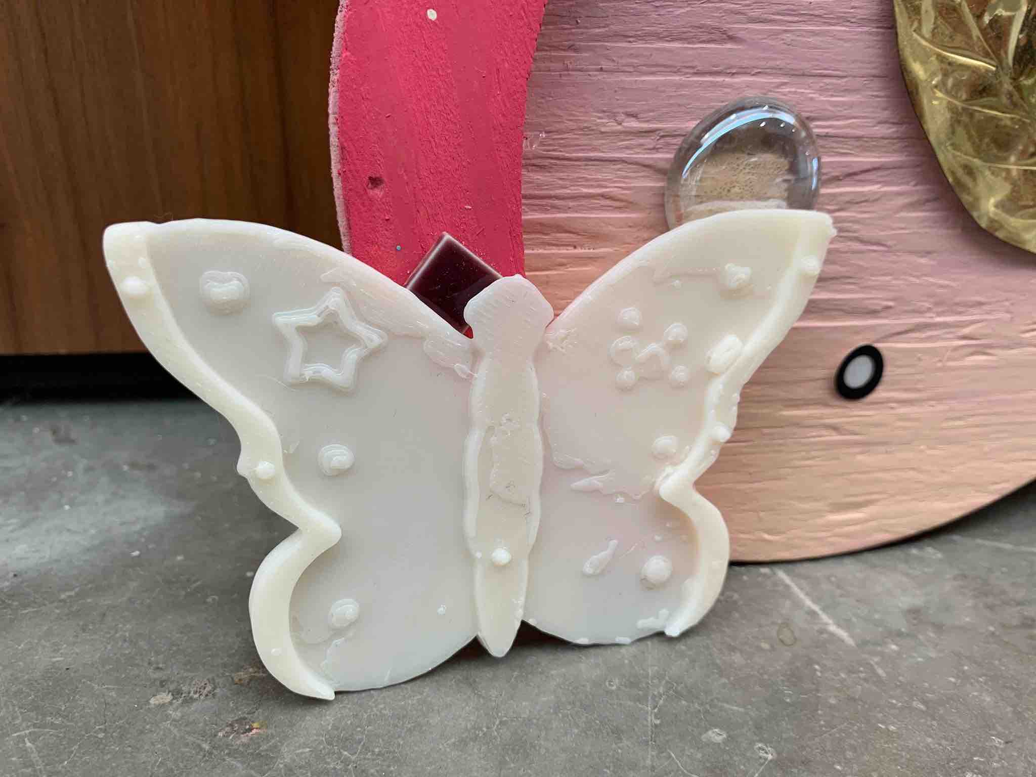
- The milk jug that is visible in my scans was a base for me to prop the butterfly up on. Knowing that my butterfly was too thin to scan it laying flat I propped it up. This was easy to remove from my scan with the background removal tool.
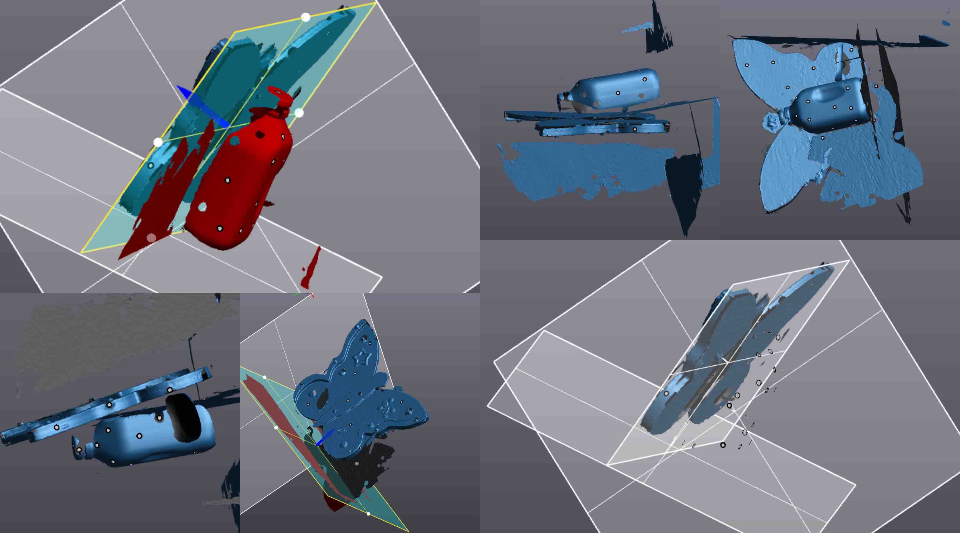
- The milk jug that is visible in my scans was a base for me to prop the butterfly up on. Knowing that my butterfly was too thin to scan it laying flat I propped it up. This was easy to remove from my scan with the background removal tool.
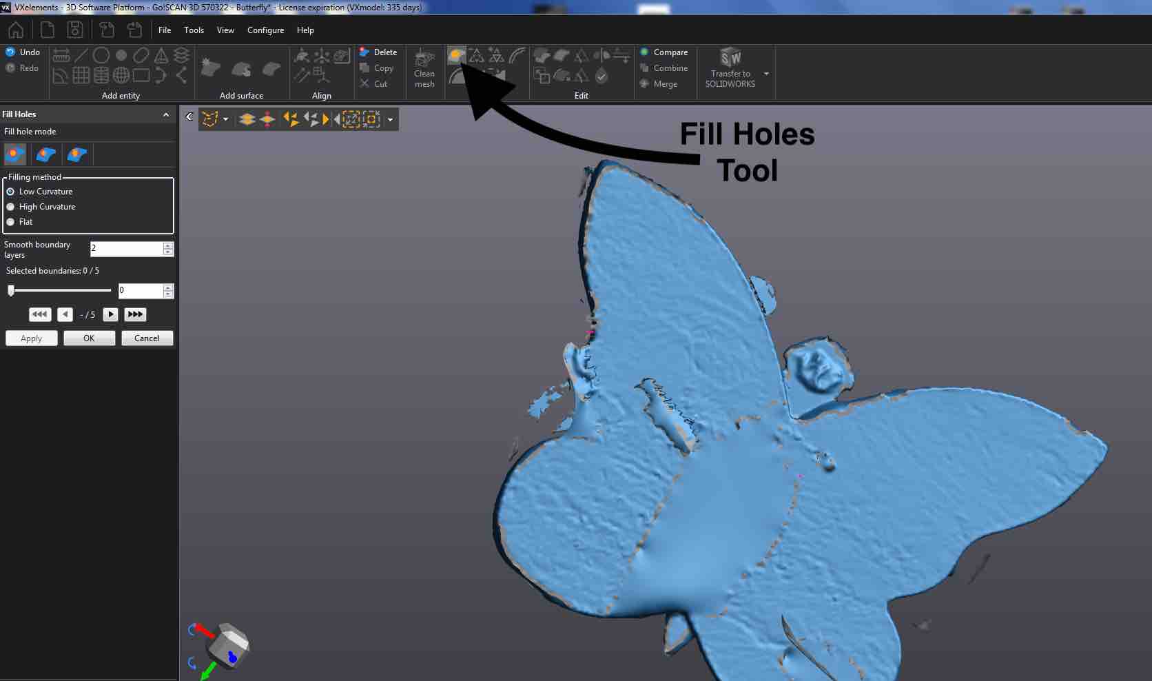
- When all of the excess noise was deleted from around my model I then began to work on filling the holes. Holes can be created by reflective surfaces and areas of the model where the light can not reach. In order to print your model the scan must be water tight. This meaning all holes have to be closed or the printer would not understand the file. To fill the hole you select the Fill Holes tool. This will show you where each hole is. On the left side of the screen are the tool preferences. Once you are satisfied with the selections click Apply. This will preview your selection. If you are satisfied with the preview select OK. This will finalize your changes.
- I made a few more minor adjustments to the faces of the scan to smooth it out. With everything cleaned up I was then ready to save my Mesh. I saved my mesh as an .stl so that I could open it in the 3D printer software to set it up to print.
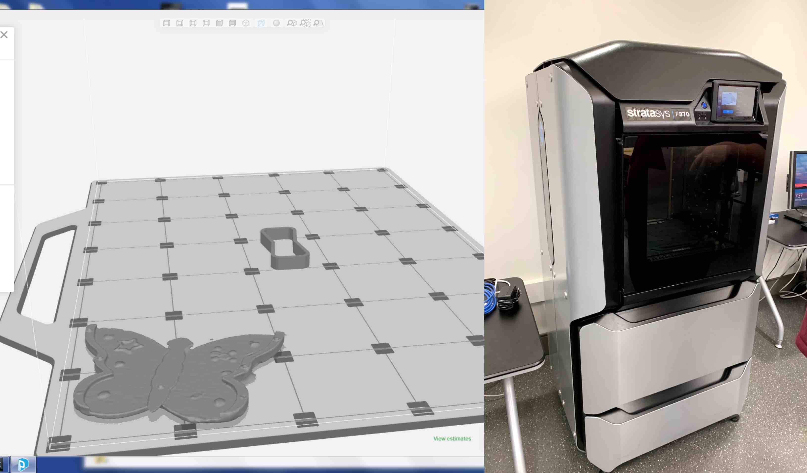
- Using the GrabCADPrint software I loaded my .stl. With my .stl oriented correctly I sent my print to the printer. I then waited for the printer to heat up. This must be done to insure that the printer head is the correct heat for extruding and that the bed become the correct heat for adhesion. This took a little over an hour. My print started after the heating process was finished and was scheduled to take 53 min. I made my final print roughly 3 inches proportionally cubed.
Optional Printing of 3D Scan
Once I returned to the printer to retrieve my print it had finished and I began the unloading process.
- When arriving at the printer the screen read Done. This meant I was able to being the unloading process.
- I opened the printer door to expose the built tray and printed piece. There is also another print behind this that is built in sync with my piece. This is to run off excess filament and be sure the print head stays clean and functioning.
- With the front of the tray in hand I pushed down to unlock it. It popped up slightly when I did this. I was then able to remove the bed from the machine.
- The next step is to remove the printed piece from the built tray. To do this you flex the tray slightly to lightly break the connection.
- Then grab an edge of the piece and pull up to remove the piece from the tray completely.
- You will notice there is additional material on the bottom of the build. This is the support material the machine lays down to built your piece up correctly. This can sometimes be removed manually with force by prying it apart. If this threatens the integrity of the piece you can use a PH bath to remove it.
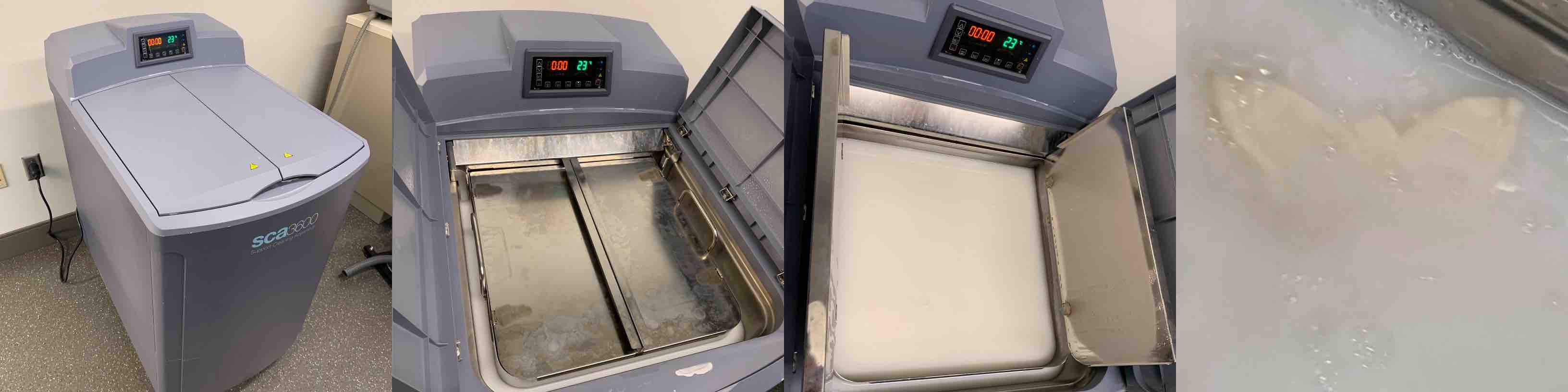
- The PH Bath is a creamy liquid that you place your 3D printed piece into. This is designed to dissolve the support material without harming the 3D Print. The bath is stored in a gray bin. The top doors open to reveal the metal bath tray.
- Open the metal doors of the bath tray to reveal the bath PH mixture. Drop the printed piece in and close up the tray and bin doors. This is now left to dissolve away. This can take up to a few hours depending on the piece size.
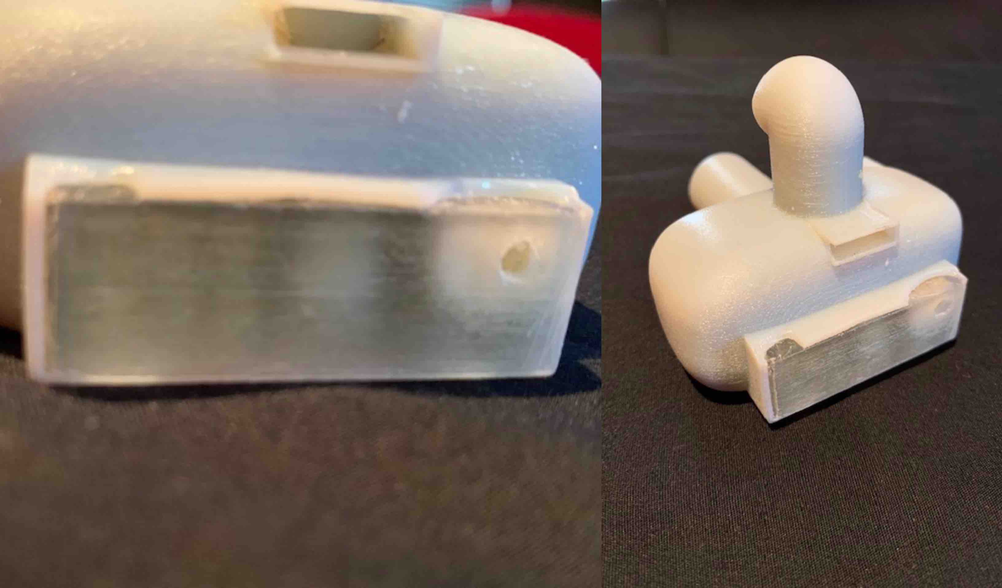
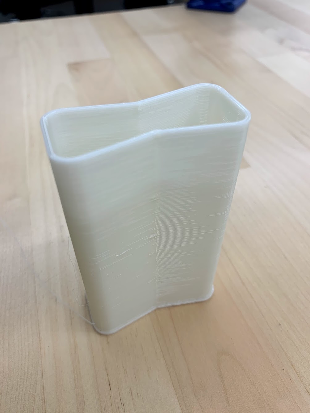
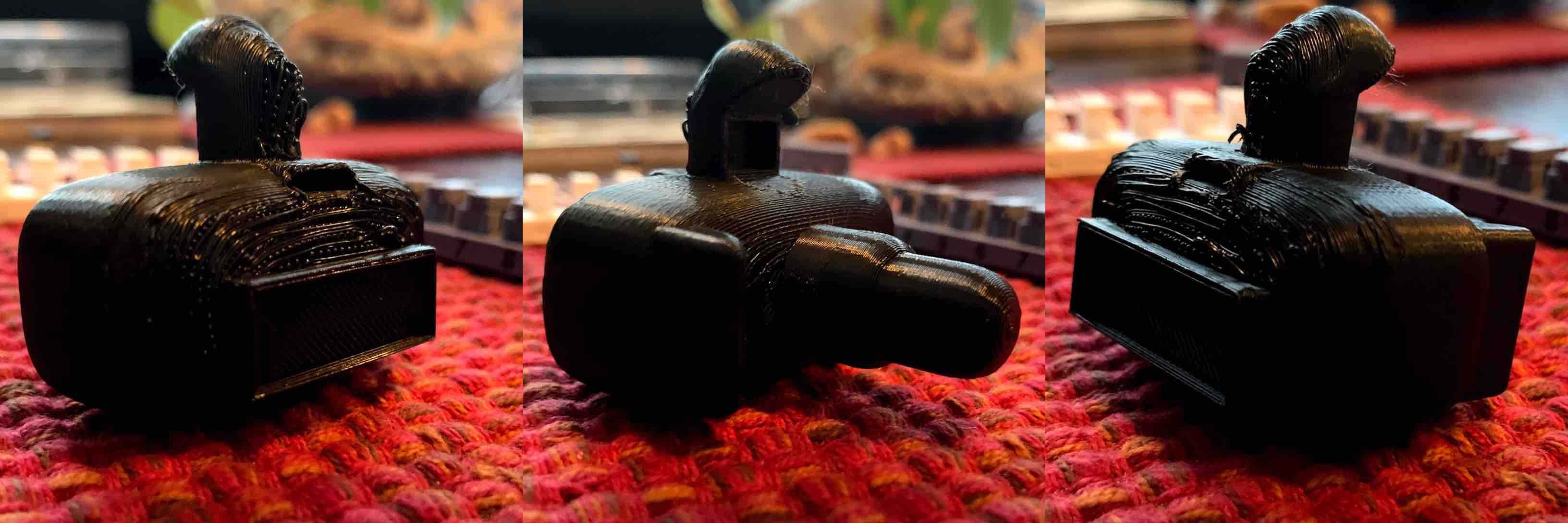
- When this is complete the support material will be removed. I wanted to leave some of the support material for demonstration. You will see on the back on my piece there is a spot where the material resembled the structure of a screen. This represents the support material. The machine must build a layer of support before it begins the print. This helps to stabilize the overall print.
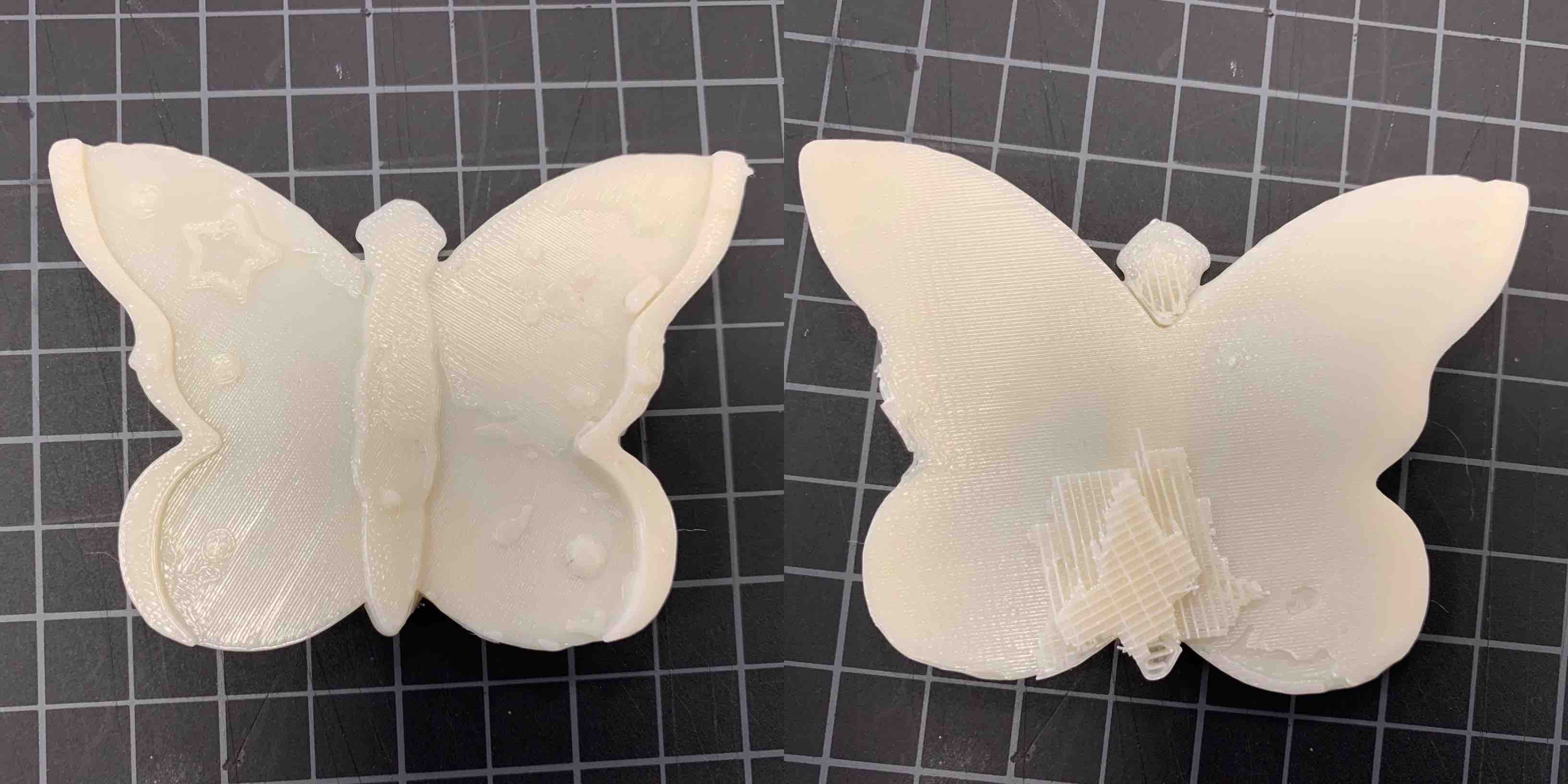
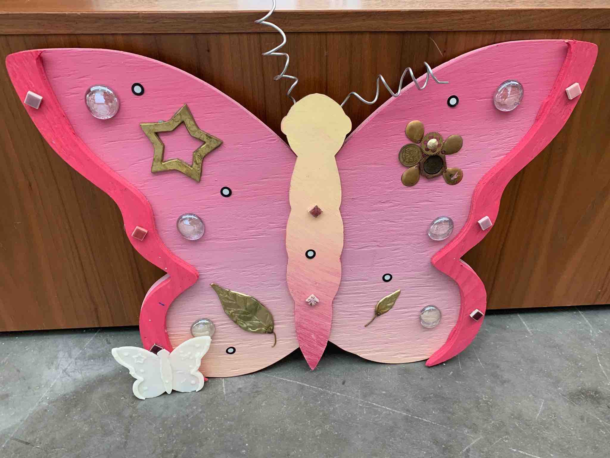
- When finished I compared the scaled down 3D Print to the large scale sculpture. I was overall very pleased with the results. Due to the size of the black scanning plate I had to tilt the piece up to that I could scan without getting the table and a lot of background noise. This left me with overhangs I needed to get under to scan. There were also multiple shiny surfaces that took some work to scan and represent. The first 3 objects I attempted to scan didn’t work as well as my Butterfly Sculpture. I was able to fill all holes to create it water tight and print my model.
Advantages and Limitations of 3D Printing
For the individual project I saw many different perspectives of the printer. I saw some advantages and some limitations.
I primarily used the Sindoh to become more familiar. Some advantages were how user friendly the software interface was. Getting my .stl to the printer was very simple. I also really liked the enclosed unit. This helped to control environmental factors mentioned above. These printers are moderately affordable, being able to find some around $1500 usd. The filament has a chip that allows the printer to read the color and status of the current filament. The printer interface itself is very user friendly as well, taking minimal steps to start and end the print. All this being said there are some limitations to mention as well.
Limitations of the machine are important to consider. When designing a part you need to consider the limitations of the machine, material and design of the file. With this print I was pushing some of the limitations with curvature, overhang and indentations. The material was pretty brittle. I had to be careful not to be too rough with the flash that stuck up. The file was designed with rounded edges as mentioned and this was difficult for the printer to achieve. It was also more difficult at smaller scales. This same limitation applied to the indents as well.
The Objet 260 is a more advanced 3D printer and therefore offers more advanced options. Although I appreciate the process, it was not the process I should have been using. The cost was one of the biggest limitations.
The other limitation I ran into was the dissolvable support material. The model made for the Objet 260 was intended to have a box printed from the clear material with loose pieces printed from the model material located within. This had to be build with support material, as the printer always uses this. I added a hole for the PH bath to access the inside and dissolve the material. This however did not work as intended. The sodium hydroxide solution could not penetrate the gelatin material and fully dissolve. Therefore the pieces did not loosen and I redesigned my piece and attempted to solve the issue.
One of the advantages of using the F370 is that when validating your print it allows you the option for the software to Repair your Model. This means if it finds any self intersections, open faces, or inverted normals it will fix them for you. This means you will not need to go back to the modeling software that was used in the beginning. This saves a lot of time for each additional fix needed. The purge tower is another advantage to using the Stratasys F370. The purge tower allows the nozzles to clean after each layer so they stay unclogged and function correctly. This adds to the longevity of the machine and consistency of future prints.
Overall, designing a challenging piece was new to me in both modeling and printing. However, when reviewing my project I decided it needed to be more challenging of a print. I decided to use the Stratasys Objet260. When that didnt work as I had anticipated I adapted and tried again with the Startysis F370. This print resulted in a print I am very proud of and I believe completes the assignment. I was pleased with my end results.
Individual Project Complications and Solutions
3D Printing
I did have some quality control issues with my print. Due to the small size and the parameters chosen to push the limitations of the printer, the bottom of the camera, based on its printed orientation, did not get created smoothly. Similar to issues when creating overhangs or bridges, once the print continued past the display window representation it had nothing to build on. The build at that point was also rounded. The first couple if layers had nothing to adhere to and became melted. This fixed itself after a while, however did leave behind an untidy look to the outside layers. The second complication was that the view port representation did not turn out. The concaved space could not hold form and the filament melted into it.
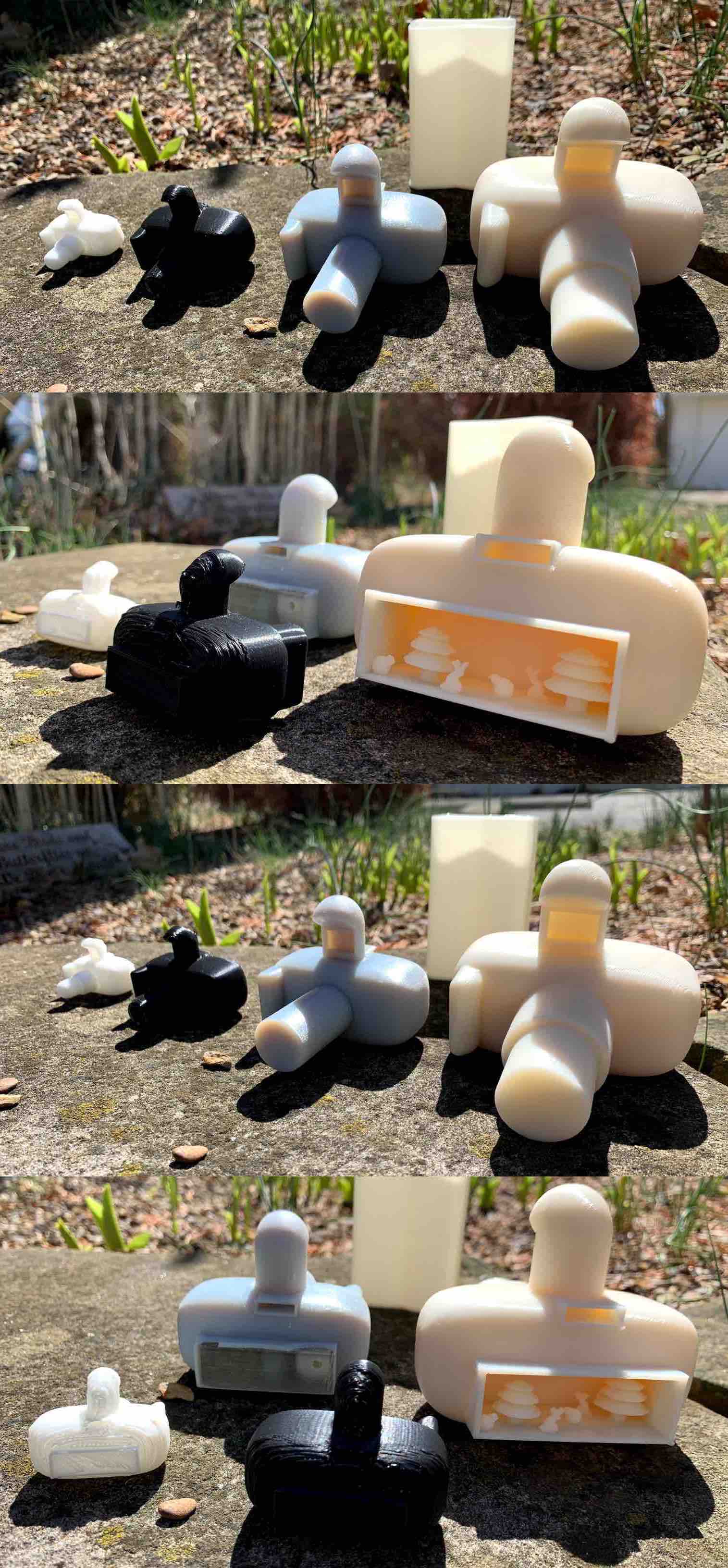
I solved these issues by printing this piece in a larger size. When scaled up it was easier to create the display screen representation. It came out quite smooth. The rounded edges of the camera were still a bit melted but had improved. The view port representation was a bit rough on the outside. However when I cut away the melted first layer the rest built quite well. Scaling was just one thing I tried to improve the print quality. I also used a black filament in a new printer to see if there was a difference from machine to machine. This did not result in much findings. Overall, the final print, I was quite pleased with.
3D Scanning
There were a few complications when it came to scanning and I had to adapt my idea many times. I tried many different scans before I created one I was satisfied with. I wanted to originally scan a deer skull I own. This proved to be too organic and have too many inlaid surfaces where the light could not reach. The scanner was also picking up the reflection of the scull. This could be deleted in the program after scanning, however it was causing some complication with the scanner.
I decided to then try a spider statue I owned that was carved from wood. It seemed to have less hard to reach surfaces, so I thought it would work better. However, I did not take into account the size of the statue and it was far too small for the scanner to capture the correct data.
I then moved on to attempting to scan one of my office plants. This proved to be much more challenging and although I was moving in a better direction for size, the plant itself had too many small details and the scanned could not see the reflective pot.
My final option landed on my butterfly sculpture created for an LCCC camp a few years back. This was large enough, had enough surfaces for the scanner to understand as well as reflective surfaces for a challenge. Overall I was able to use this as a scan and print it in stratasys F370 printer.