18. Mechanical Design and Machine Design
This week I worked with my team to determine what type of machine we might want to make.
Useful links
Research
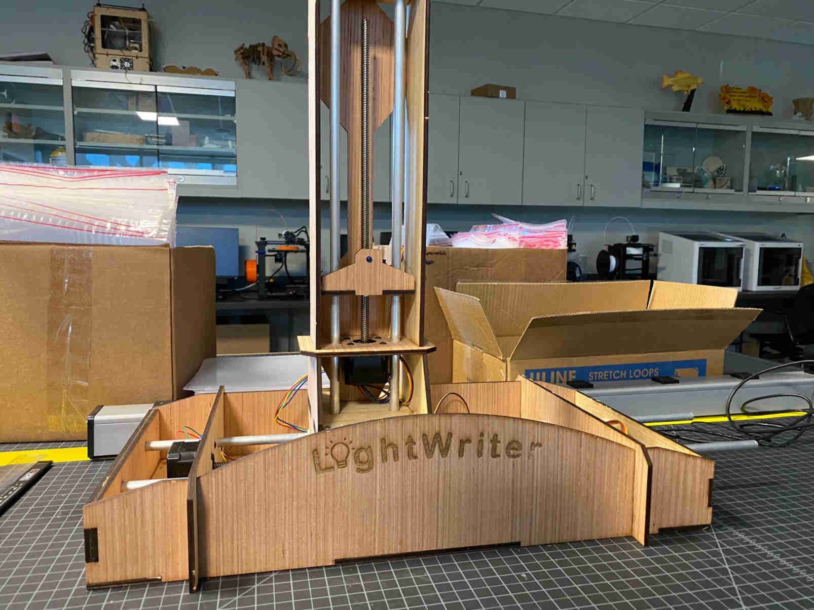
Meshing interest in machine design and photography techniques we decided to create a 2-axis machine that could follow G-Code and create light drawing with a long exposure. By using a light mounted to our machine, the 2 axis can move along the lead screws of the step motors. This will allow the light to follow the axis as they communicate with the step motor through a wired connecting. The G-Code will tell the step motors when to move and how. The light will then be tracked by the long exposure of the camera. A Nikon D3400 is being used here.
I contributed to the group assignment by building the prototype in Fusion 360 and animating it. I also cut the final version from wood and assisted in the building process.
Prototyping Sketch
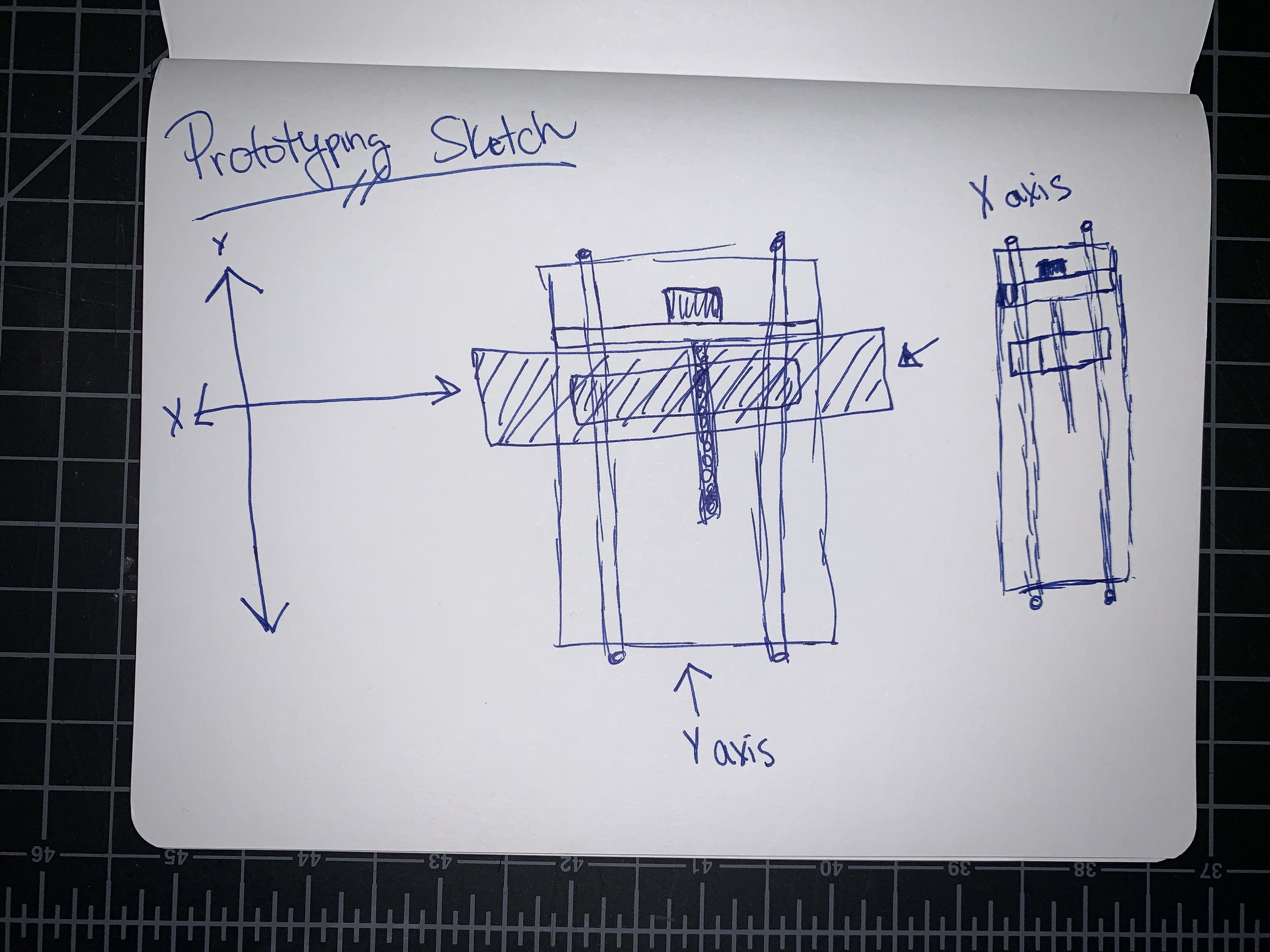
Axis Y
I knew I wanted to complete an animation of the motion of our project so I decided to complete the model as 3 components. The motion of the Y axis is where I started.
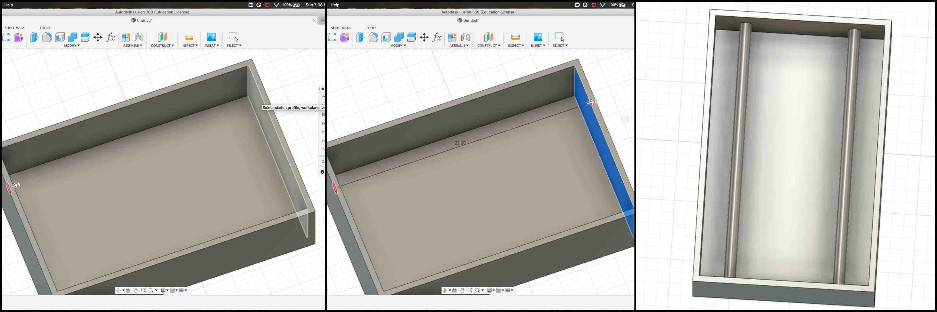
To create the 3D model of our prototyping sketch I created a new component. In this component I began by sketching a box. I used dimensions that would reflect the prototype in accuracy.
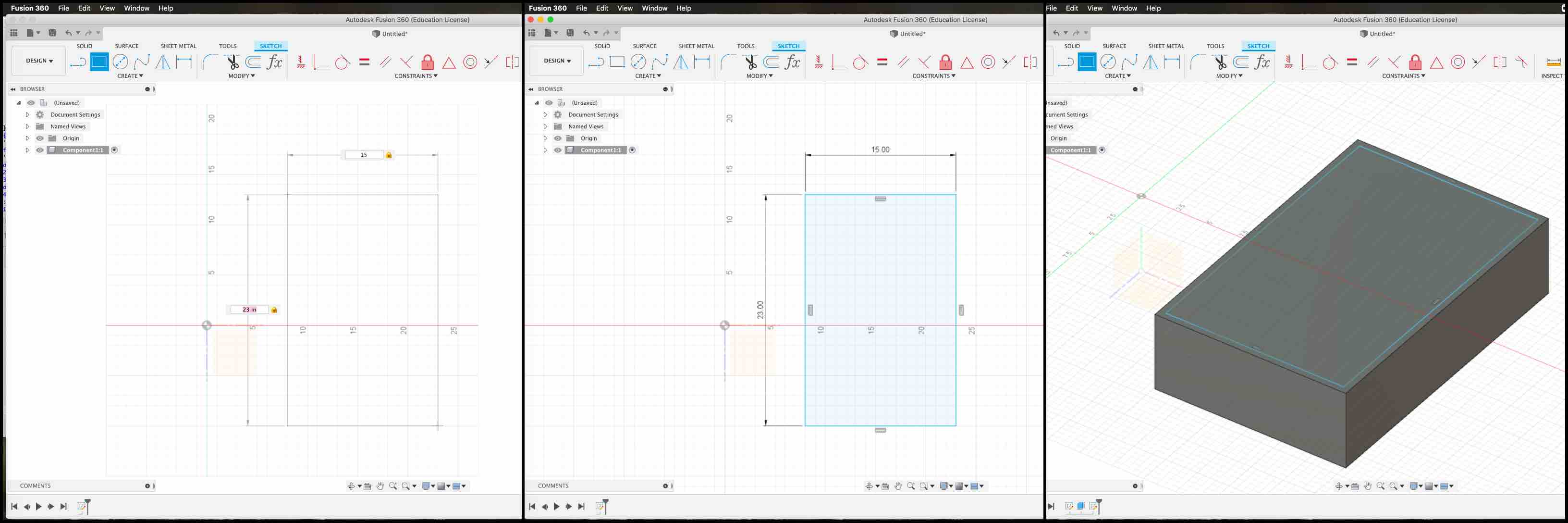
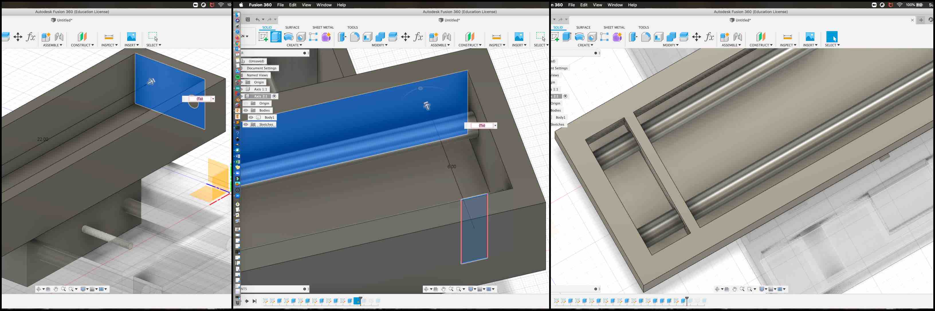
I then selected the top of the box and did another 2-point rectangular sketch. I extruded it down and cut from the original model. This created the sides of the box and the inside opened up.
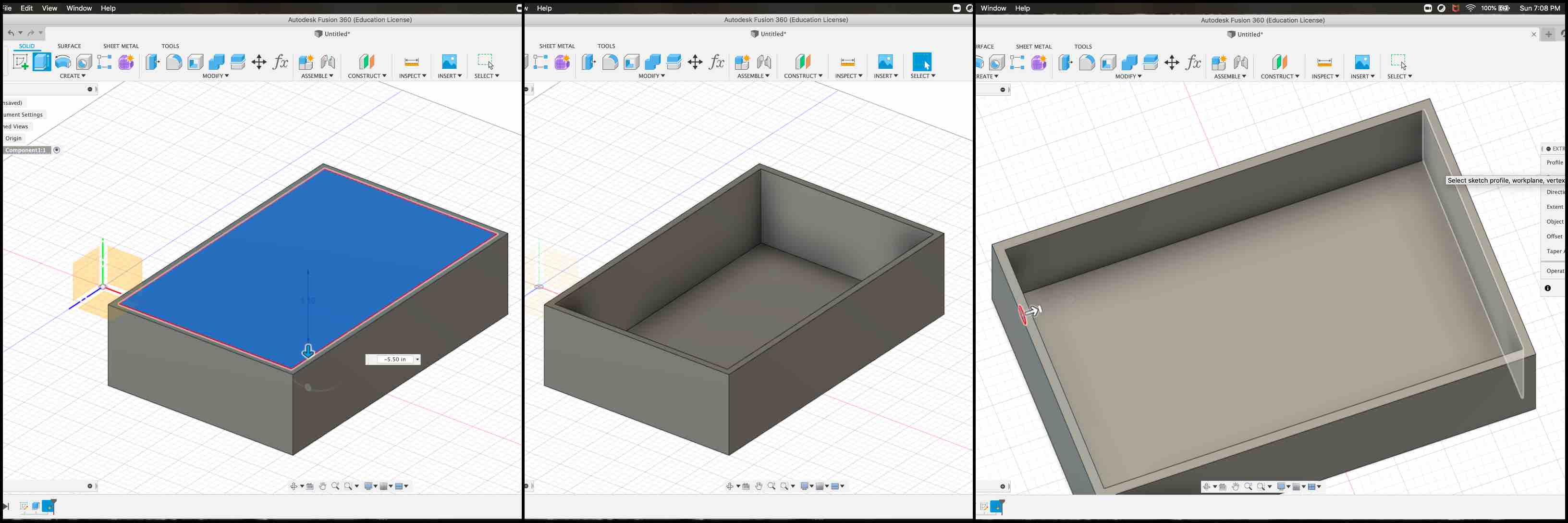
I created the rails next by sketching a circle on the inside wall of the box. I then extruded each to the length of the other side of the box. This created the metal half inch rails.
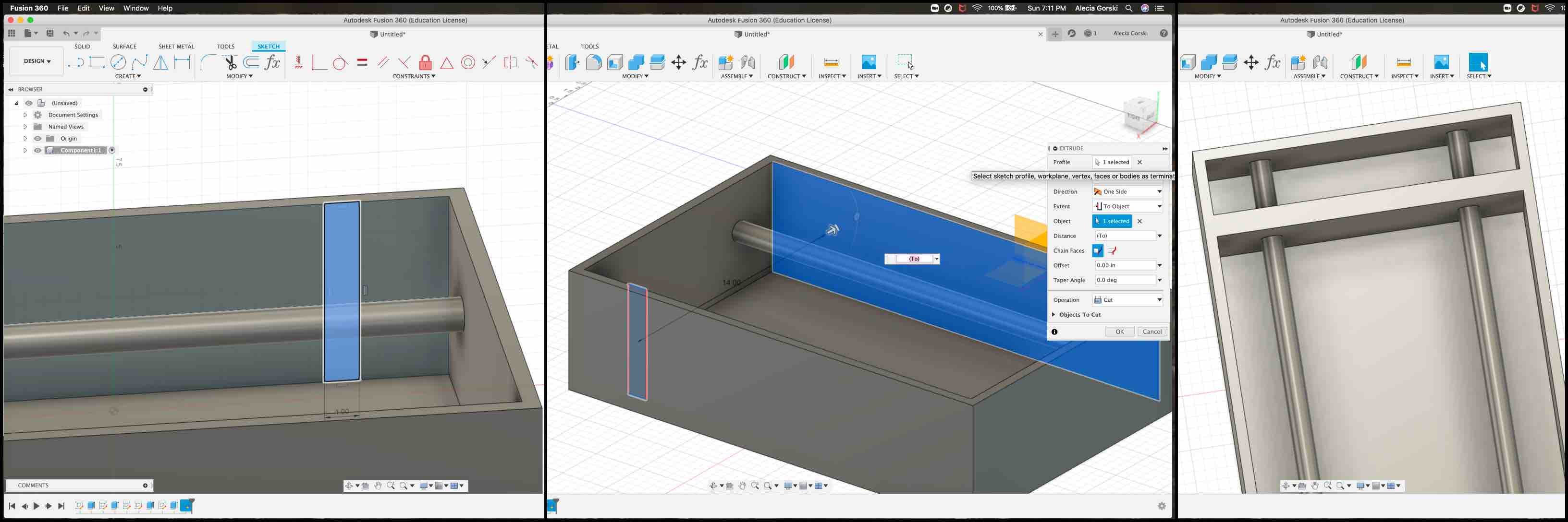
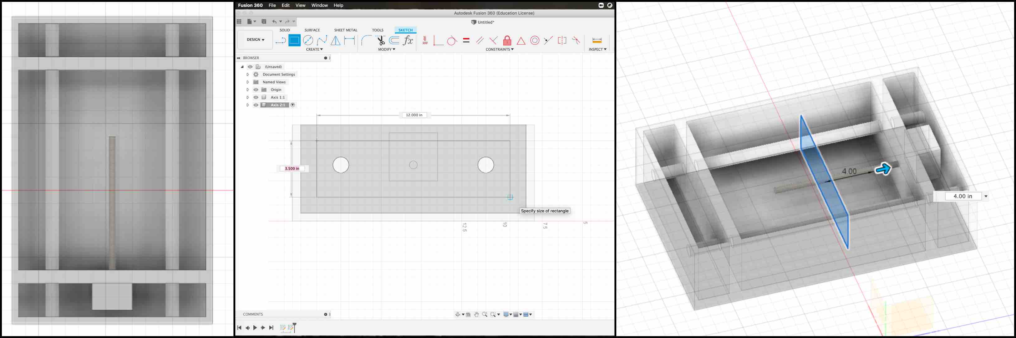
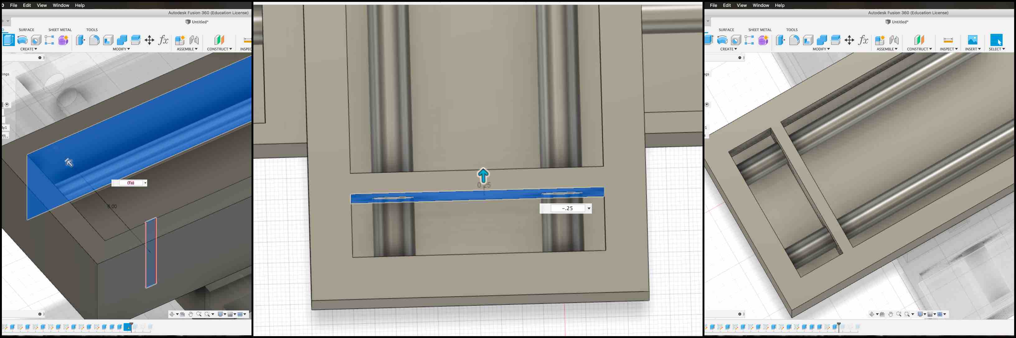
Creating another sketch on the wall that runs parallel to the rails I sketched a rectangle. I then extruded this rectangle to the other side, passing through both rails. I joined all the components. This gave me a place to run the lead screw of the step motor through and a place holder to fix the step motor too. For stability of the rails I added another to the other side.
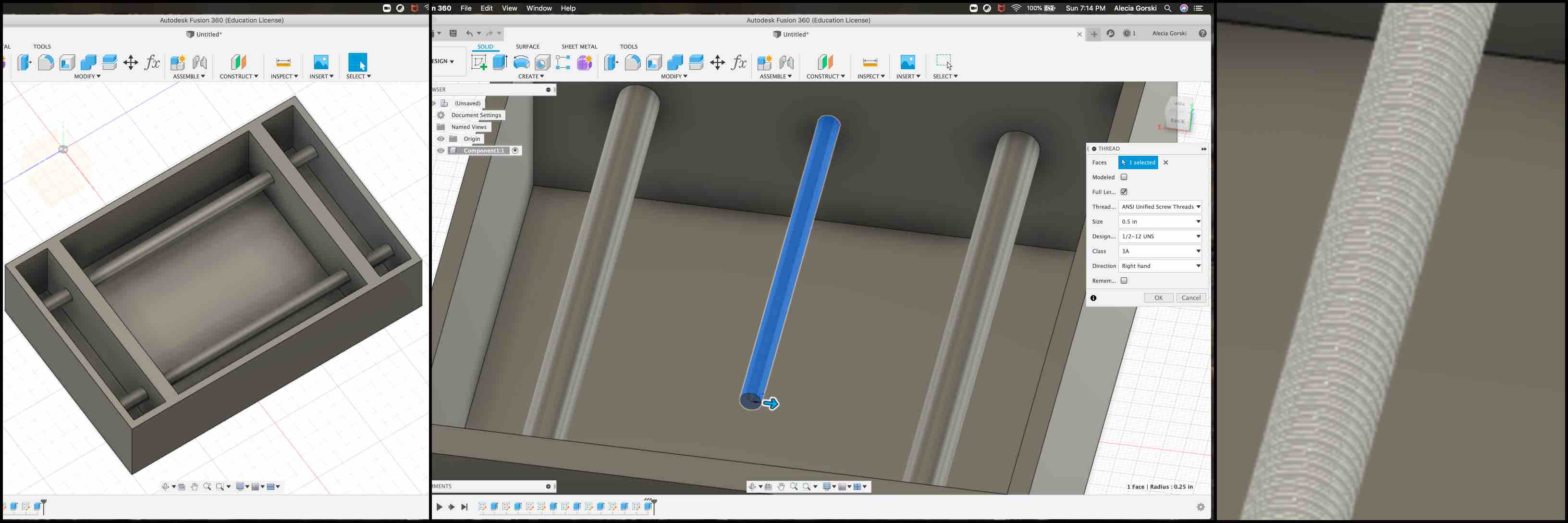
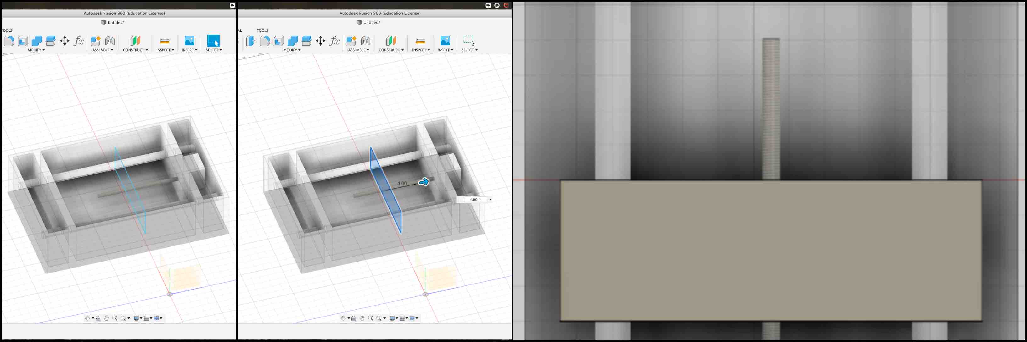
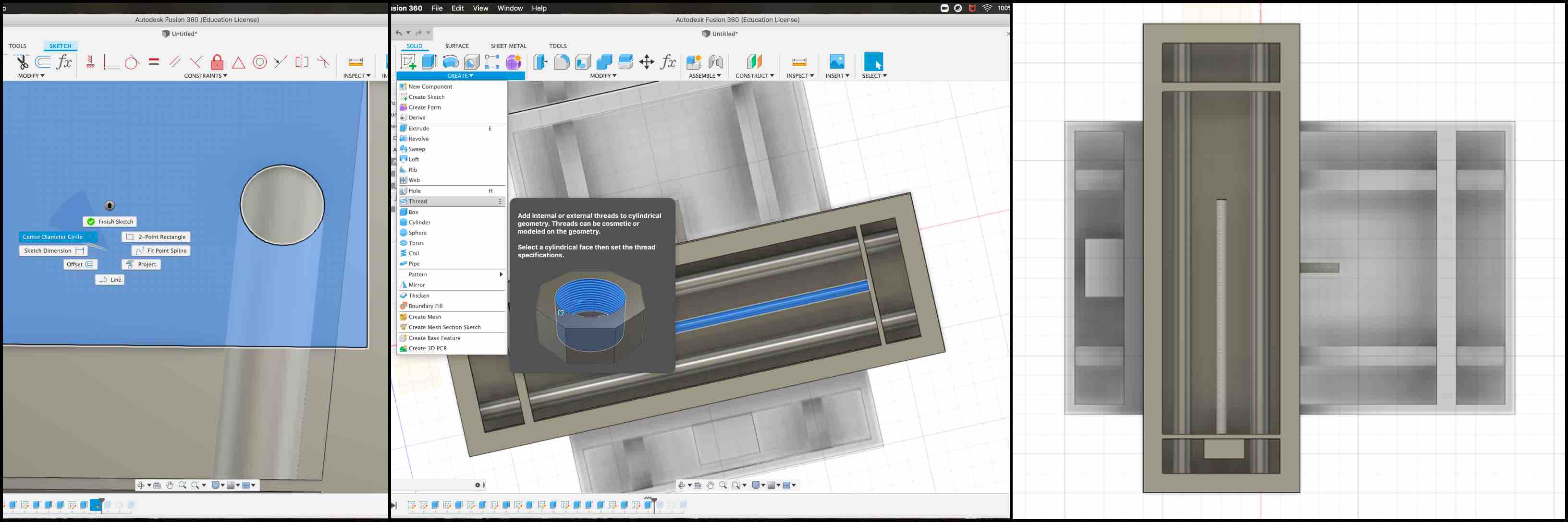
Once this was complete I extruded another half inch circle 3/4 of the way through the open area. I applied a thread to this extruded cylinder to represent the lead screw of the step motor.
I then created the representation of the step motor by sketching a box on the opposite wall of the lead screw.
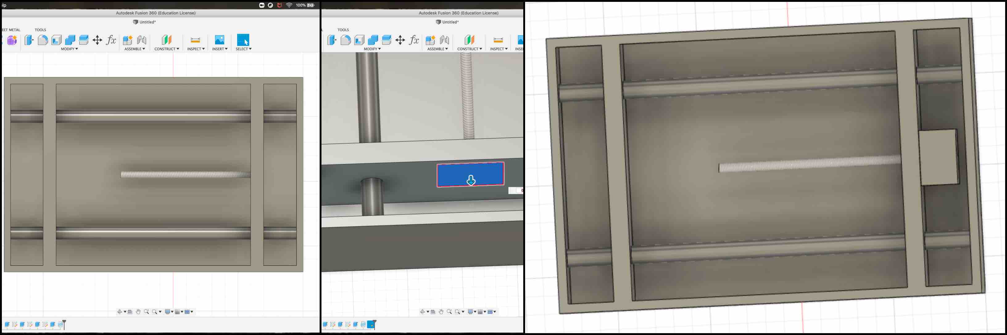
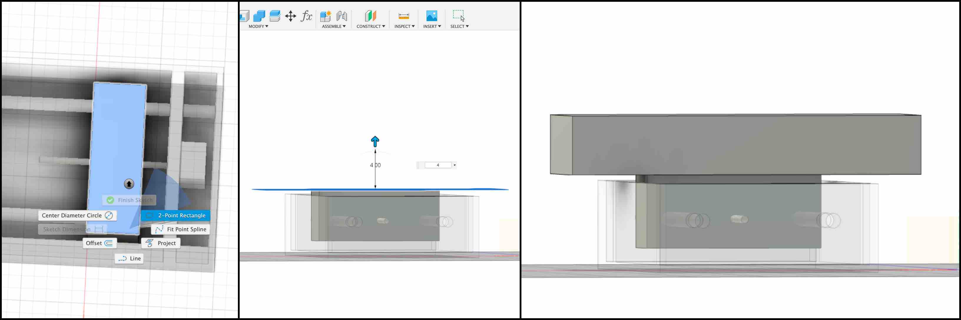
Once this was completed I moved on to working with the mechanisms on the X axis. I started a new component and began to work on that layer. This turned the completed component into an opaque sketch. Working with the new component layer I began created the box that would move along the rails by the functions of the step motor.
Axis X
This had to be in the new component so that I could animate the movement along the axis. By extruding the rectangle created I was sure to overlap the rails and the lead screws.
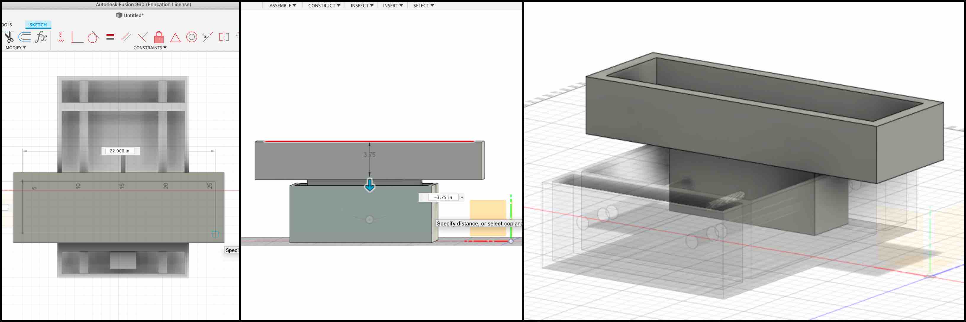
I created a new sketch based on the top of the box I just made. I then created another two point rectangle to represent the new axis.
I completed similar steps as described above to hollow the box out.
I then created the rails in the same steps a before.
In the new axis box I then made the walls to stabilize the rails.
I created the representation of the second step motor and applied the lead screw thread.
LED Axis
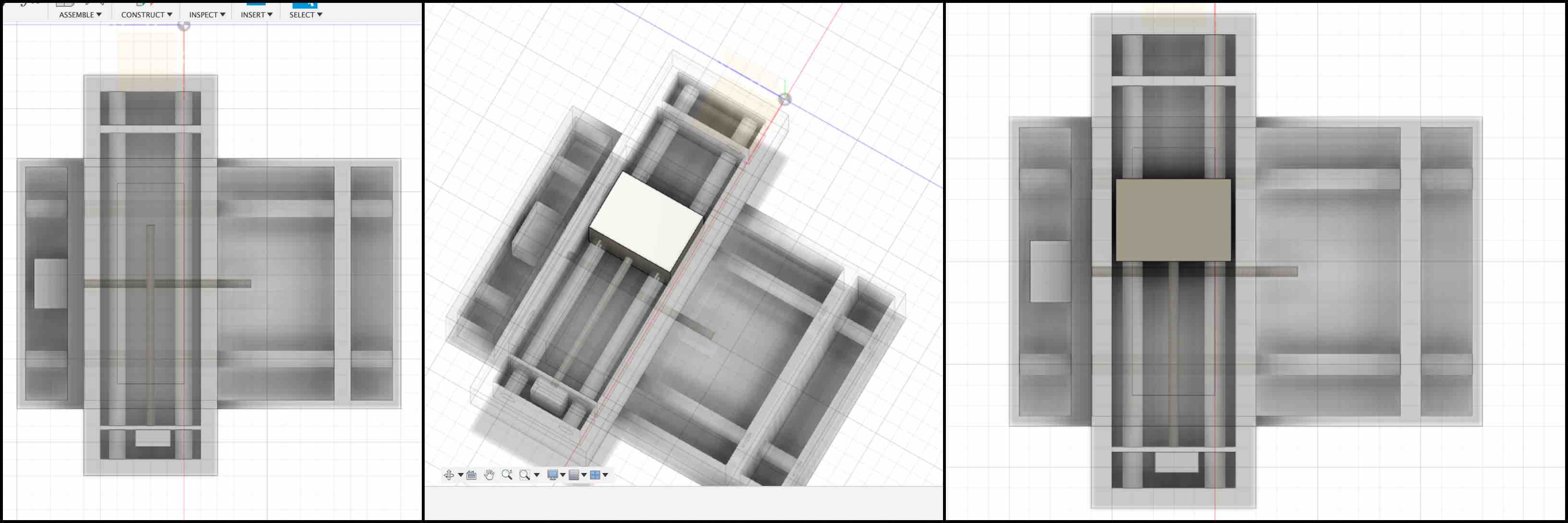
With the two axis’ now created I started a new component. This then turned the first two axis into opaque sketches. As I had done before I created a sketch to overlap the rails and lead screw of the new axis created. This is then extruded to represent the box where the LED would be secured in order to move it during the long exposure.
Modeled 3D Animation
My contributions copied from group site for clear documnetation:
Animation of Intended Function -Alecia Gorski
The design was created in Fusion 360 and more can be found about this on Alecia Gorski’s page.
Testing Results -Alecia Gorski
Using the materials we could find in our lab we put together a rough testing of the machine. The motion of the LED with the long exposure created the light design. We started simple with a box.
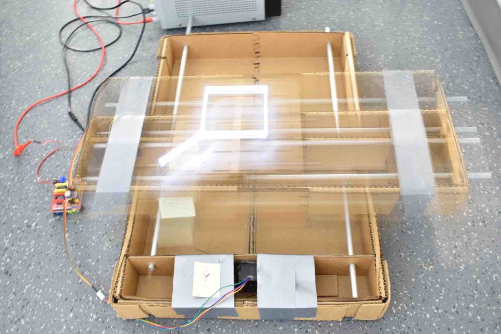
The best exposures can come from being in a darker area. This allows just the light from the LED to be let into the camera during the long exposure.
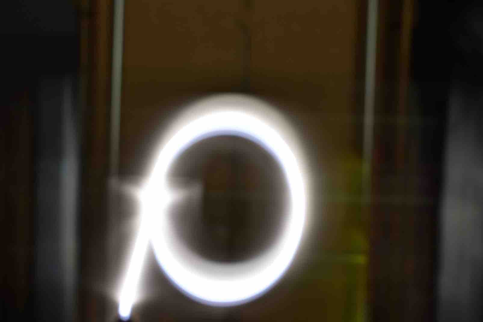
We were successful in coding the machine to complete a square as well as a circle.

Fabrication + Assembly -Alecia Gorski
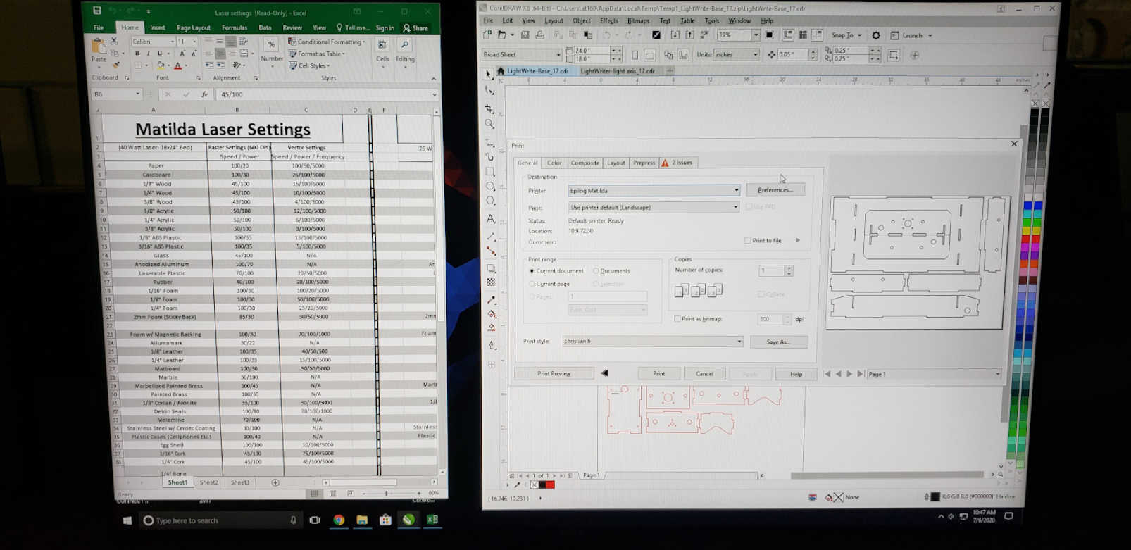
Need to Cut the wood down to 18 x 24 inches to fit into Matilda, the laser cutter.
Sheets of Wood:
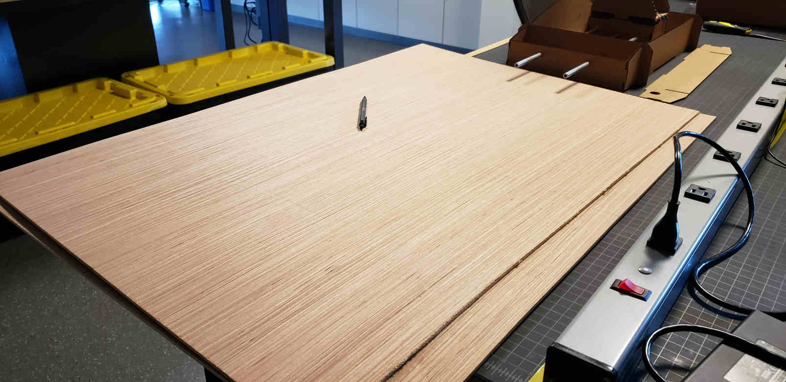
Here is Ryan cutting it down:
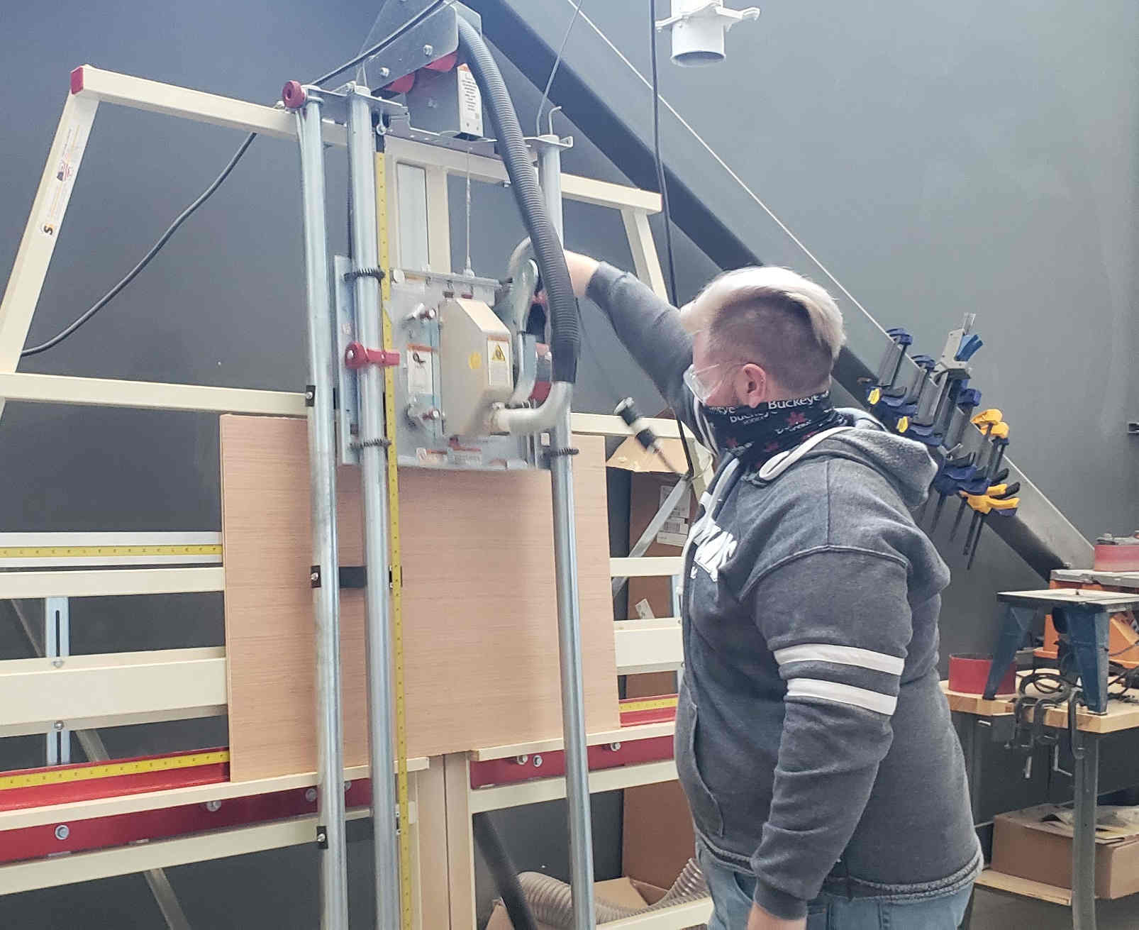
Setting up Matilda to cut the LightWriter pieces out + engrave the logo
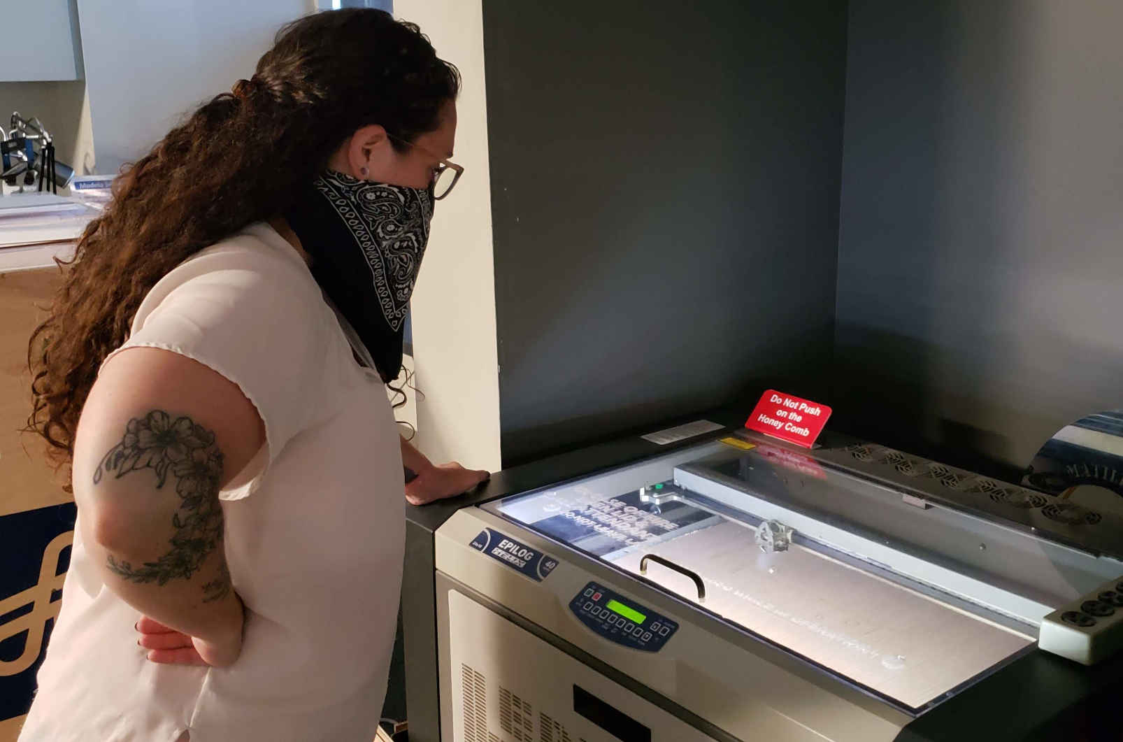
Alecia and Hallie took turns watching Matilda for safety (no fire hazards here).
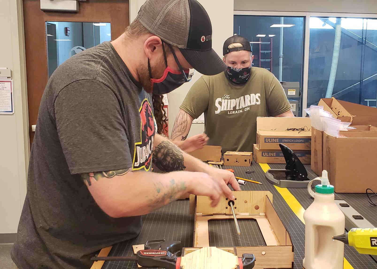
Assembly coming along with Chris, Hallie, Ryan, and Alecia.
Chris and Ryan:
IT’S ALIVE!!