7. Computer Controlled Machining
This week I worked on defining how the CNC router could make something big that related to my final project. I try to work by the spiral development rule and keep things applicable.
Research on Make Something Big!
The assignment being to Make Something Big with no other regulations I decided to theme my assignment around my final project idea. My final project being a Solar Panel Leaf Light I designed a charging station that can be displayed in two different ways and disassemble to be stored flat. This tabled will be engraved with the laser with educational solar phases, along with and educational degree triangle to obtain optimal solar absorption.
Useful links
Group Contribution
For this assignment the group was asked to test runout, alignment, speeds, feeds, and toolpaths for our machine. As a group we worked to change the tooling, zero the axis’s, and run test cuts to determine the outcomes. We measured the differences and posted the results to the group page.
Designing My Concept
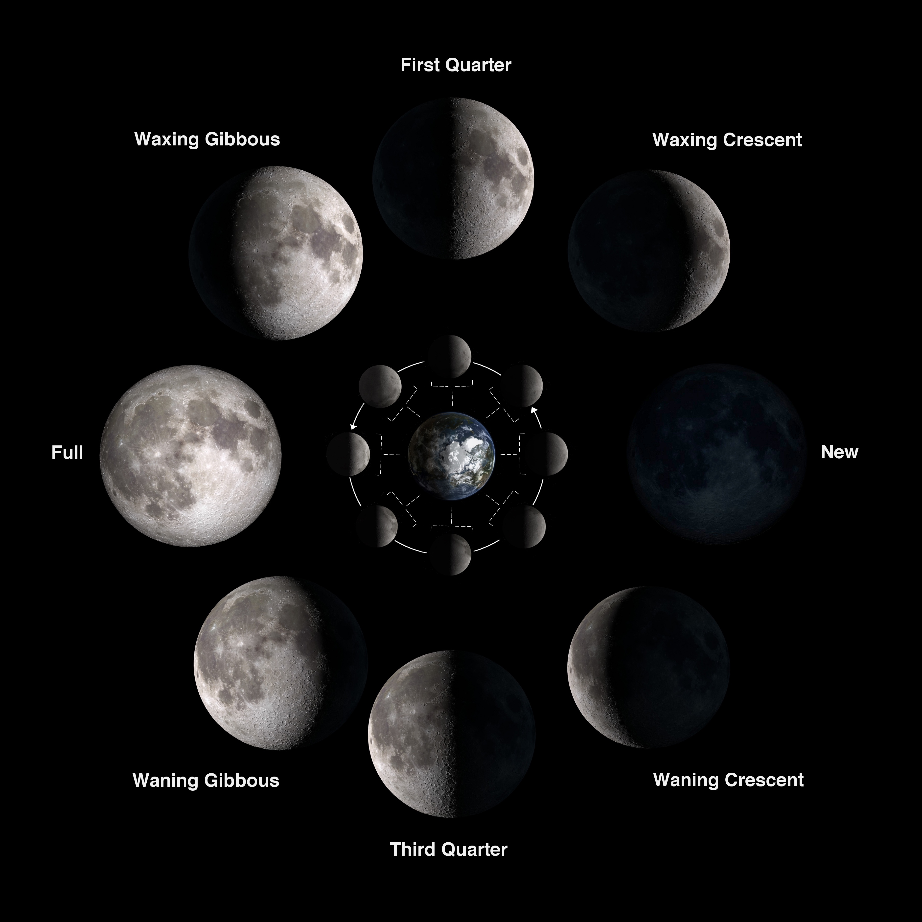
For these designs I wanted to match the theme of my final project being Solar Education. This was represented throughout the whole design. The engravings located in the top of the shorter table option will represent solar phases of the moon. A solar phase being defined by the Encyclopedia Britannica as the varying appearances of a celestial body as different amounts of the disk are seen (from Earth, ordinarily) to be illuminated by the Sun.

With the inspiration from the above image each moon phase will be shown in a circular pattern, leaving the middle open for the degree triangle. The Solar representation for the top of the taller design option will be left free of design for he middle to be focused on the placement of the degree triangle for optimal solar energy obtained.
The leaf representation found in both the table design and the light itself educationally represent the photosynthesis process. The process of green plants to absorb sunlight and use it to create food. The reaction of the carbon dioxide and the water create the food source that produces a byproduct of oxygen.
With these concepts included in my theme of solar education the tables can be used to teach from as well.
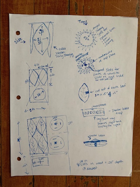
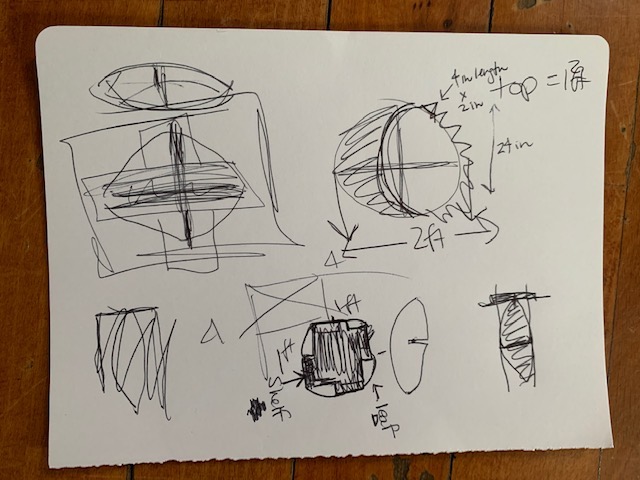
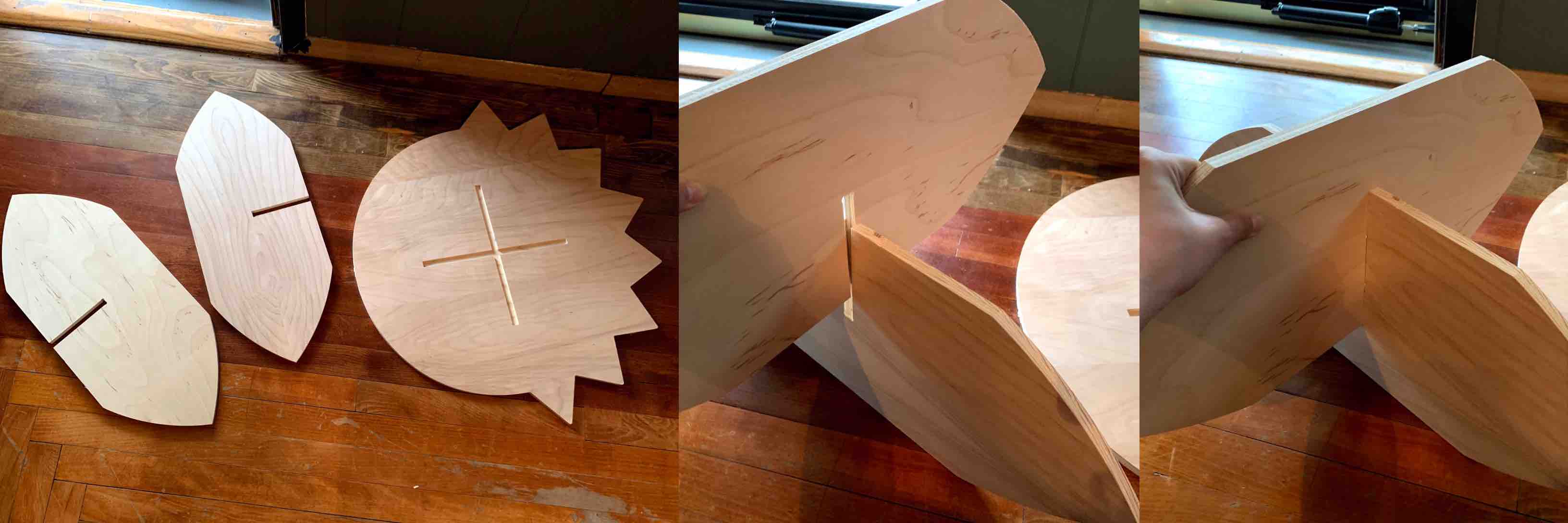
With these parameters in mind I was still struggling to conceptualize how much space I had and what sizes I should be making my pieces. I decided to switch first to good ol’ fashioned pin and paper. Being able to sketch all of my intended pieces, along with how many of each is needed. I created the leaf shape, with the suggested measurements. I then created perspective sketches to determine how many of each piece I needed. I chose four leaf shapes to serve as legs. My original dimensional suggestions were instantly too large. I took my idea and I scaled it down. This gave me room on my board to create the top and bottom of my table.
I decided to design a solar sun shape for the top. This went along with my theme. Addressing the stability issue I decided to engrave a half inch into the underside of the top in the positions where each leaf leg comes in contact with the top of the table. I decided it still needed more so I added a base, which was a replication of the top for symmetry. With more space available on my 4 foot by 8 foot sheet of plywood a thought dawned on me, this could be multipurpose! I decided to design the leaf legs to have slots removed form the edge of each into the middle. This was then stabilized further with a shelf attached through the open slots. and fit to the size available inside the table design. With the slots designed into my leaf legs the table can be disassembled. With two legs now intersecting on their sides through the slots the additional table top can be placed on top. The underside of this table top is engraved .25” for the intersection to be stabilized. This smaller table is an educational piece, to be engraved with the phases of the moon. This also sits much closer to the ground, accommodating children.
Fusion 360 Parametric Modeling
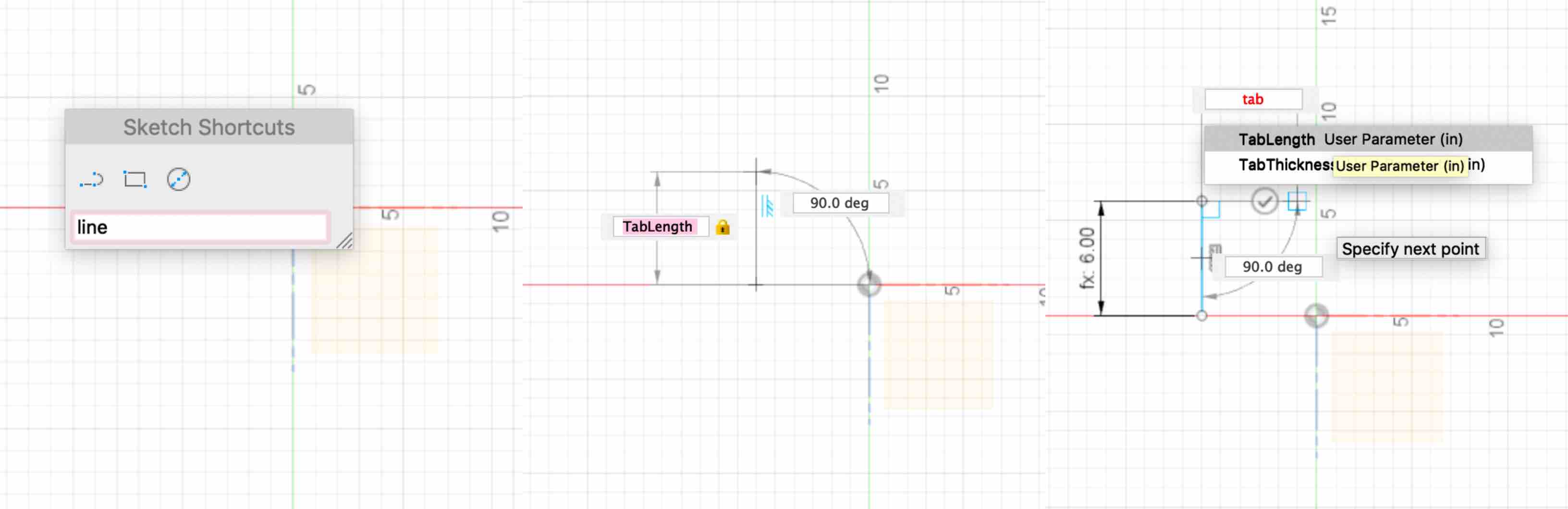
With these concepts in mind I began using Fusion 360 to create each piece of the table. Knowing that the material thickness would need to stay consistent, as well as the tab depth, length and thickness I used this information to set parametric parameters.
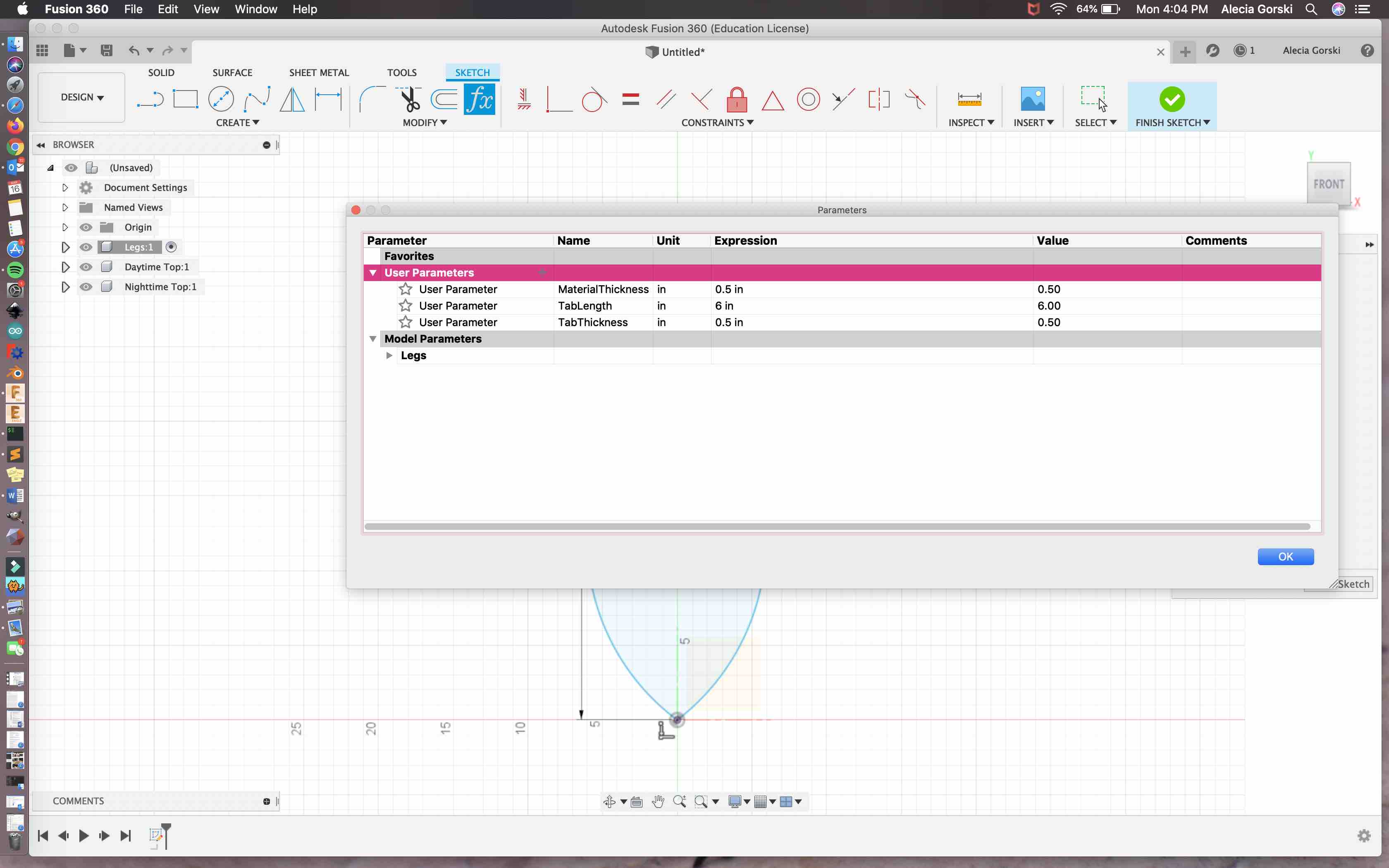
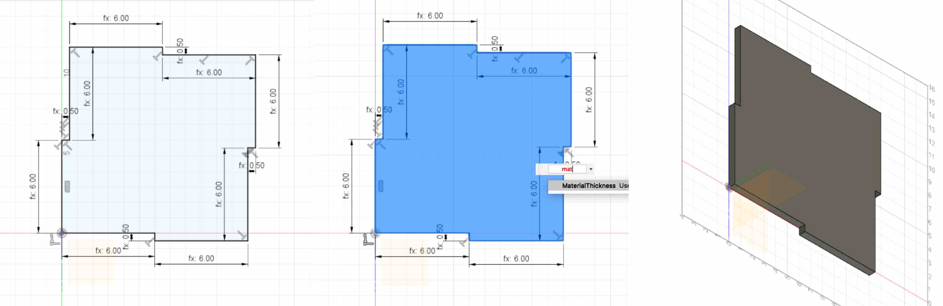
As I designed and built each piece I used the parameters to assign the relative lengths. This was built to represent the .5” thickness of my intended material. My other corresponding dimensions were built to represent accurate measurements in relation to my 4 foot by 8 foot sheet of birch plywood. I used a similar design process that I had completed in week 3 when constructing parametric designs with cardboard. I selected the plane I chose to build on. I then used the line tool as well as the three point arc tool to sketch the face of my shape. When the face was connected It created a blue color fill to the shape.
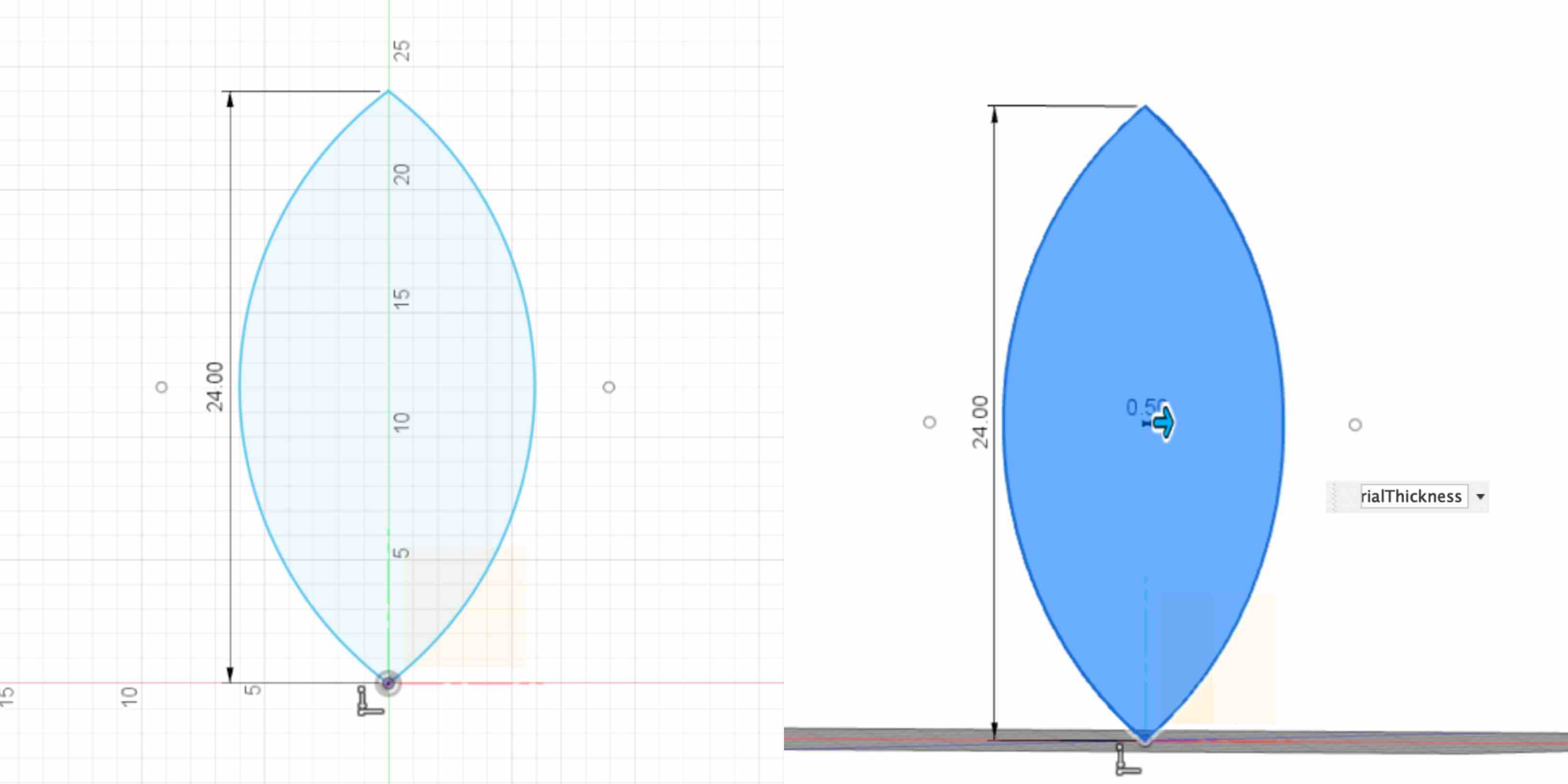
Once the shape was created I was able to extrude this to match my parametric parameter of Material Thickness to represent .50”. - Remember that to extrude in the Fusion 360 software you can use the hot key Q. - With the base of my shape created I was not able to add the tab slot for the table shelf. This will also help with the stability of the build. The lengths and depth is designed based on my parametric parameters as well. - As noted in week 3 this means when a change is made to the measurement in the parameters window it will change all associated lines in the design. This allows me to easily design pieces to adjust tabs and lengths to thicknesses of different materials. -
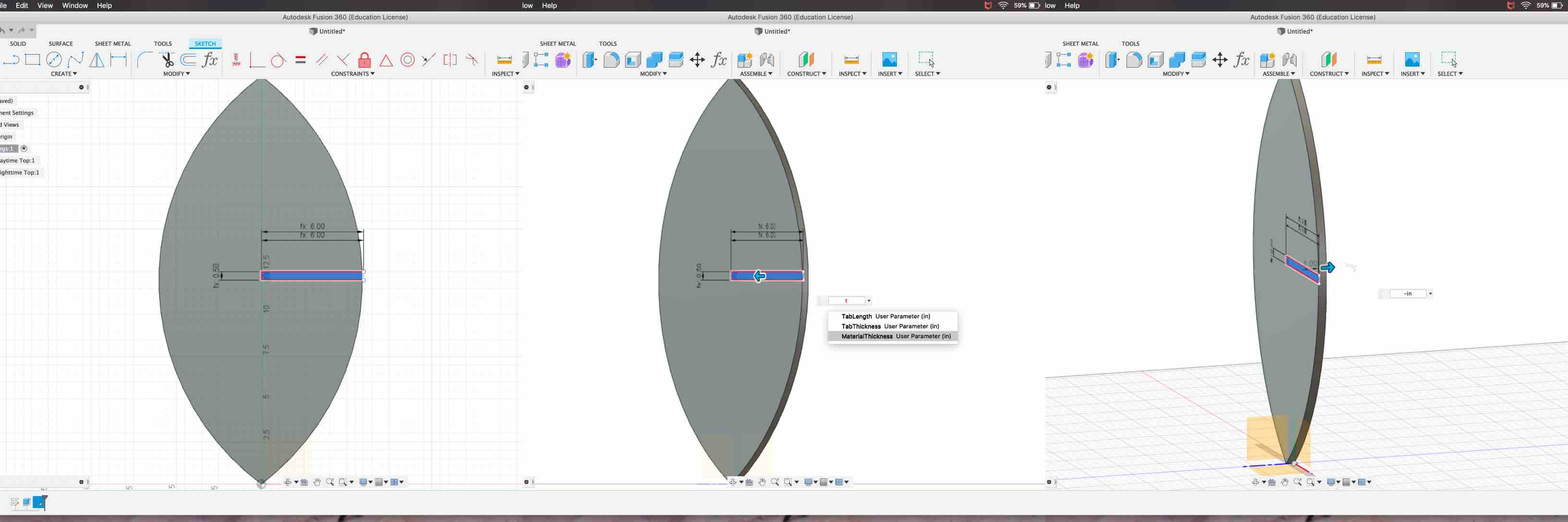
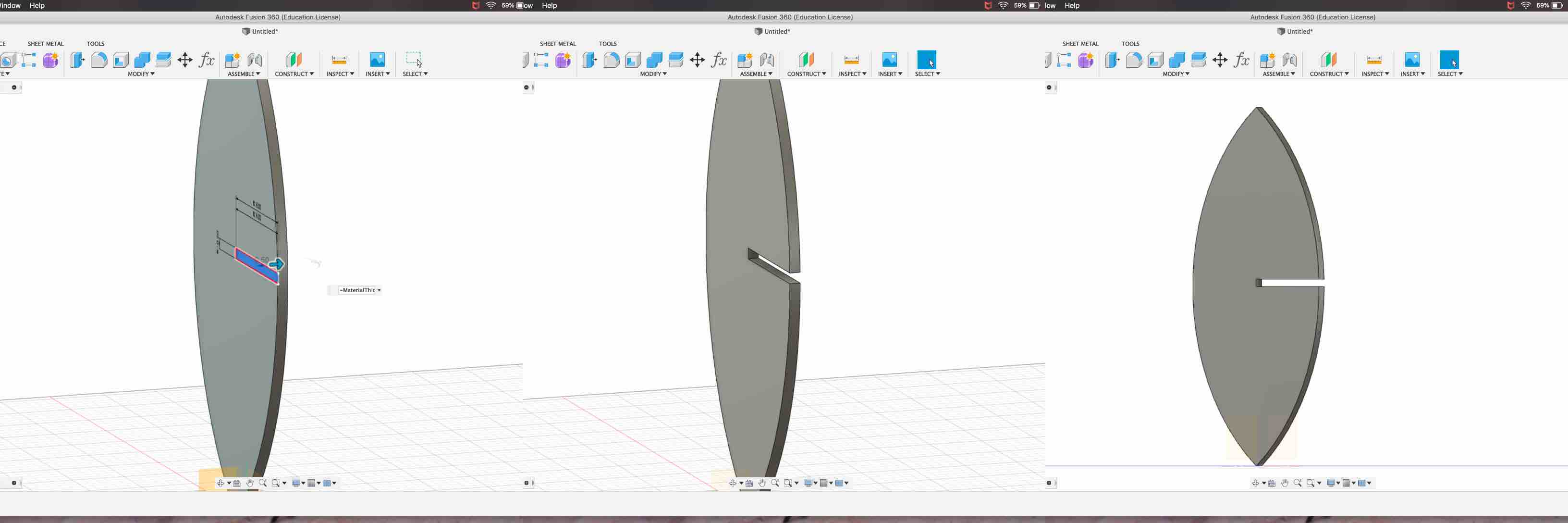
To create the tab and assign each length I must start a sketch in the face of my structure. With the face selected I can hit the hot key S and this will provide me with a window of sketching options. I then choose to create Line. With the area selected I would like to place the tab I can plot my first point of the line. I then am able to assign it with the corresponding parametric length. Creating all 3 lengths of the tab and extending this off the edge of the structure will create a new face. This can be selected on its own and extruded to match material thickness. This then open the tab and the creation is complete.
The next step was to create the shelf design. I wanted to be sure to match the tab on the leaf leg structure to the insert that will be created on the shelf. To do this I kept consistency with assigning my parameters as the different insert lengths. I began my sketch on the z plane so that I could assemble the shelf with the leg representation in Fusion 360 and be sure they sync well. I worked in clockwise motion and created the tab edge first with the line tool in sketch mode, indented at a right angle for the material thickness, and then again, at a negative 90 degrees, lengthening the shelf by the tab length. This completes one side of the structure.
After completing the first side I was able to repeat this process to make each additional side. With each side connected and the measurements listed I could see that the basic construction appeared to match my overall concept.
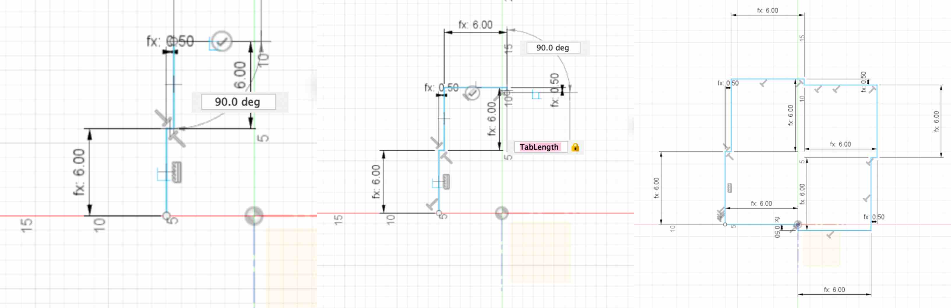
As each side is connected it again turns the face of the shape created to a light blue color. I then selected the face of the shelf built and extruded it by the material length parameter. This completed the construction of the modeled shelf piece.
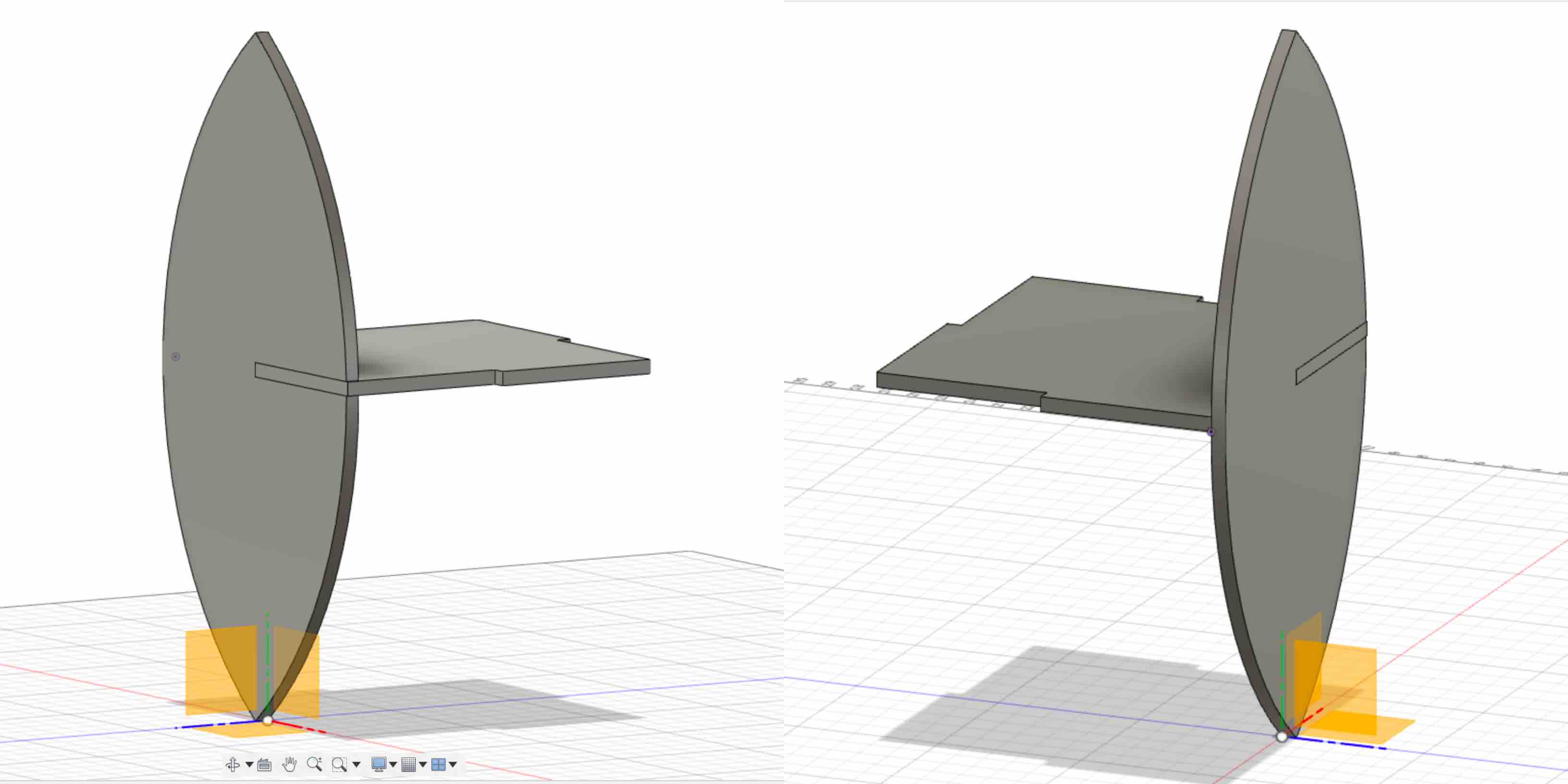
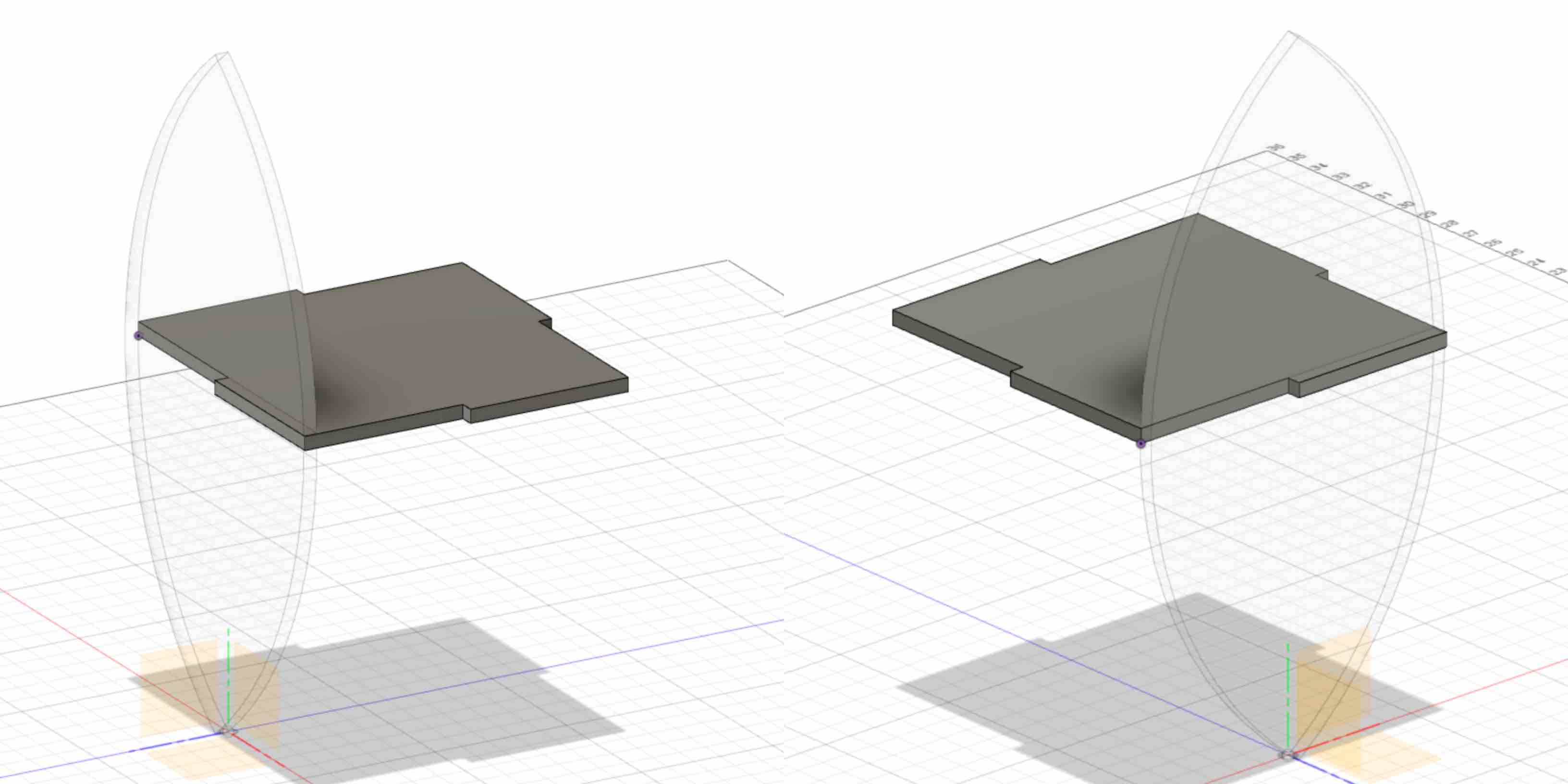
After modeling both pieces in Fusion 360 I now wanted to check that they lined up on a software level. This is my first attempt at checking my work as I go to be sure it will come together correctly. This will also help to reduce material waste. The cardboard test listed below is another example of this prototyping in order to reduce end waste.
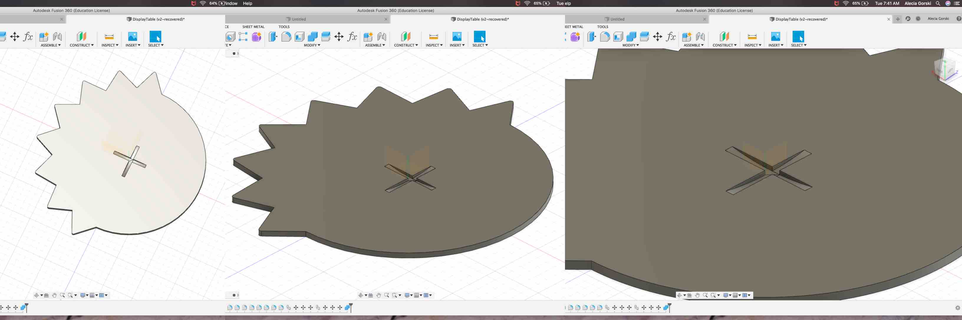
As shown below I used the Fusion 360 software to line up the two pieces. This was made easier by working with Fusion 360 previously and realizing the need to build accurately on plane representation as well as based on material. I also turned the solid view of the leaf leg shape off to show how well the connection is made. This is easy to do by changing the fish eye from all components to just the shelf component. This then displaces a see through “shadow” of the leaf leg and the shelf stays the focus. Overall I was very pleased with where the connections were made and I moved on to work on my next component.
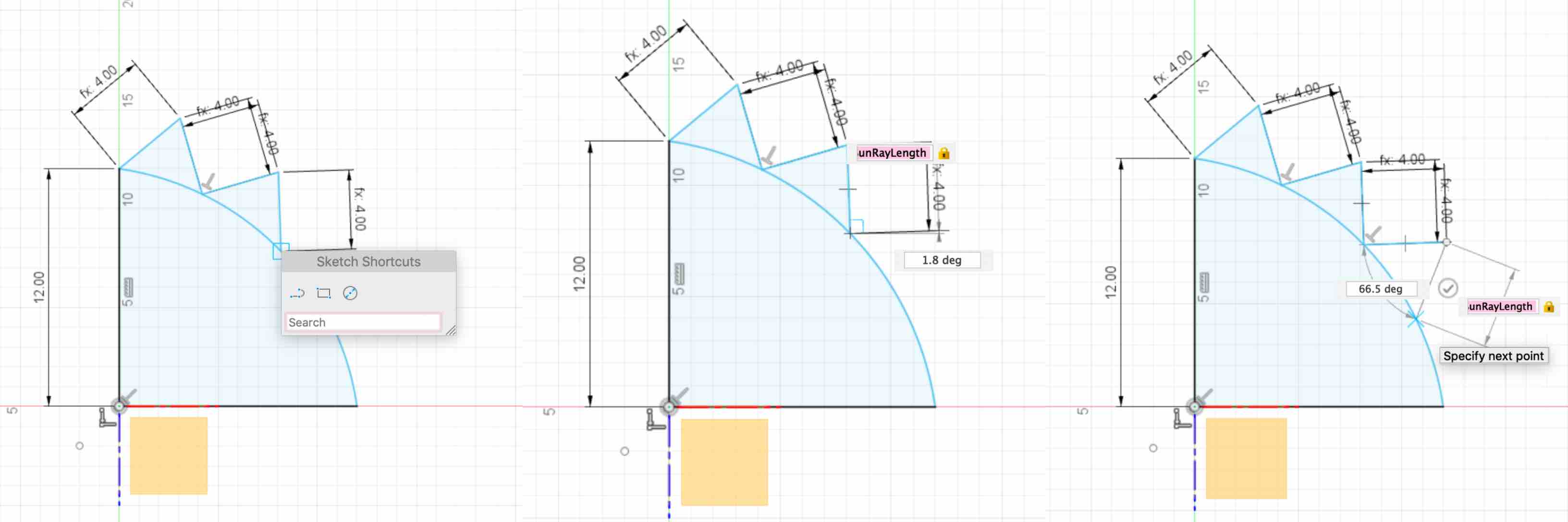
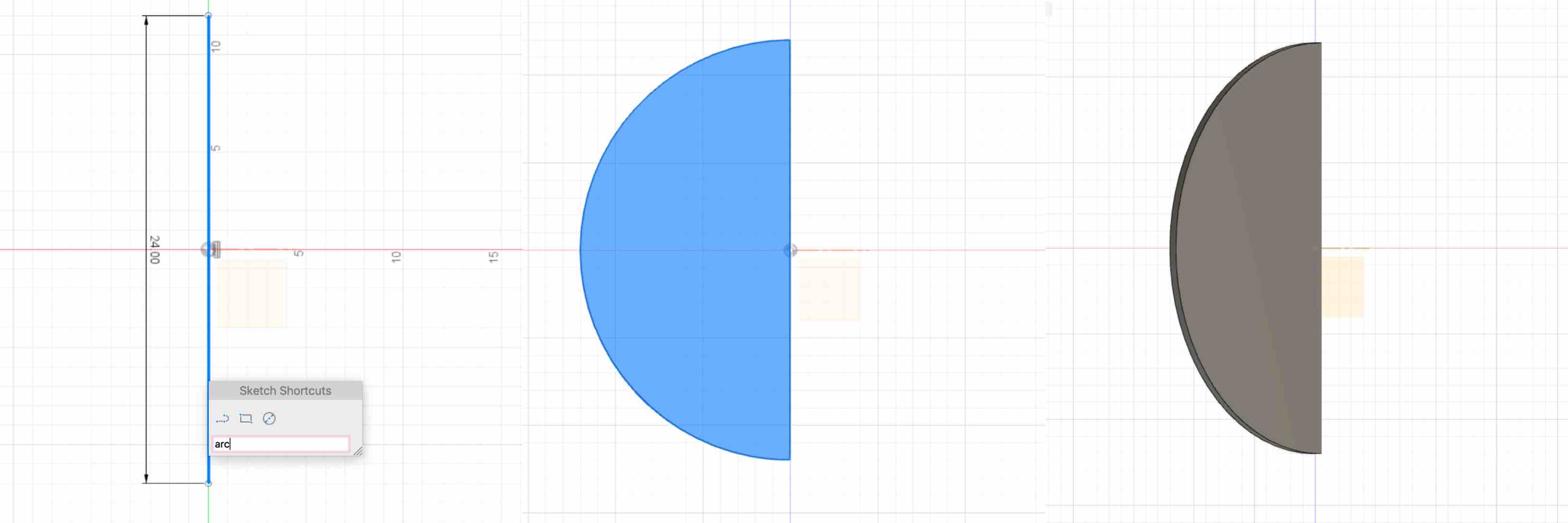
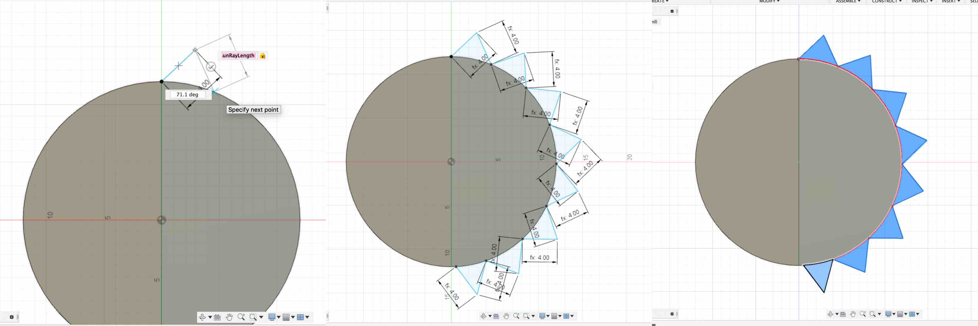
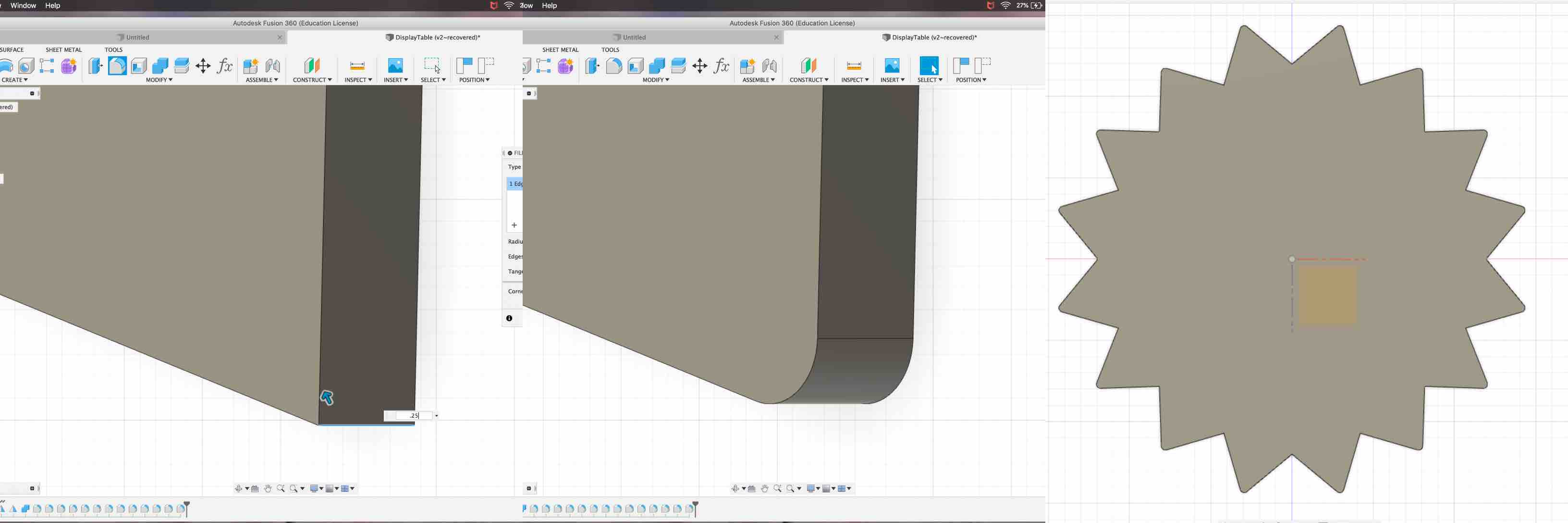
Once the leaf leg and the middle shelf was completed and double checked for alignment I began to create my table top shape. Deciding to keep with the Solar Education theme I wanted the top to be in the shape of a sun. I struggled a bit to create the shape. I started with trying to sketch a full circle. I then created a representation of a ray and attempted to copy and multiply it along the circular path. This was harder than I thought and did not create the piece as a whole as I would have liked. Instead Fusion created each additional ray representation as a new component and had to be adjusted separately. I deleted this whole concept and started over. I decided a better way to complete this task would be to create one quadrant of the shape and copy, paste and move each to the correct position. I created a quadrant of a circle using the line tool and the two-point arc tool. I then started another sketch onto the new face. This prompted me to create another parameter called Sun Ray Length. I used this to make each length of the sun rays to keep them parametrically consistent and adjustable. With the face of my new shape light blue I was able to extrude it to the thickness of the material.
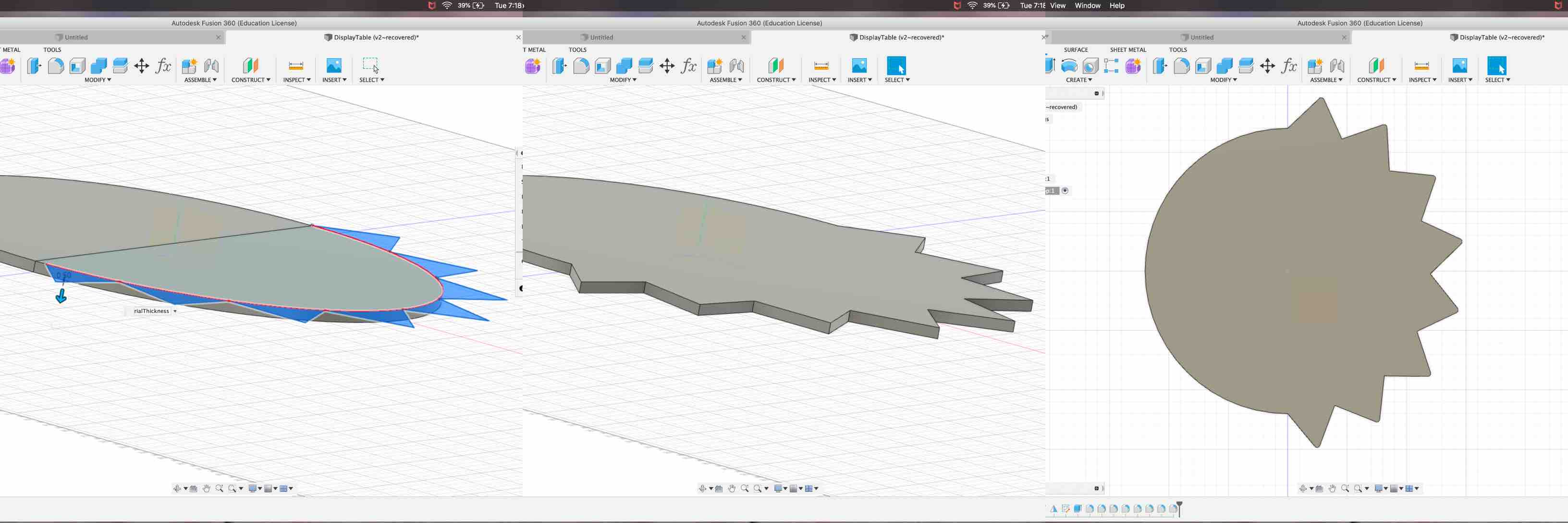
I then used the copy, paste and move option to multiply this quadrant and place it below the first one. I adjusted this piece to line up with the fist. I then took the half shape that is created and copy, pasted and moved to the right of the first. This came together to complete my overall sun shape for the top representation of the sun.
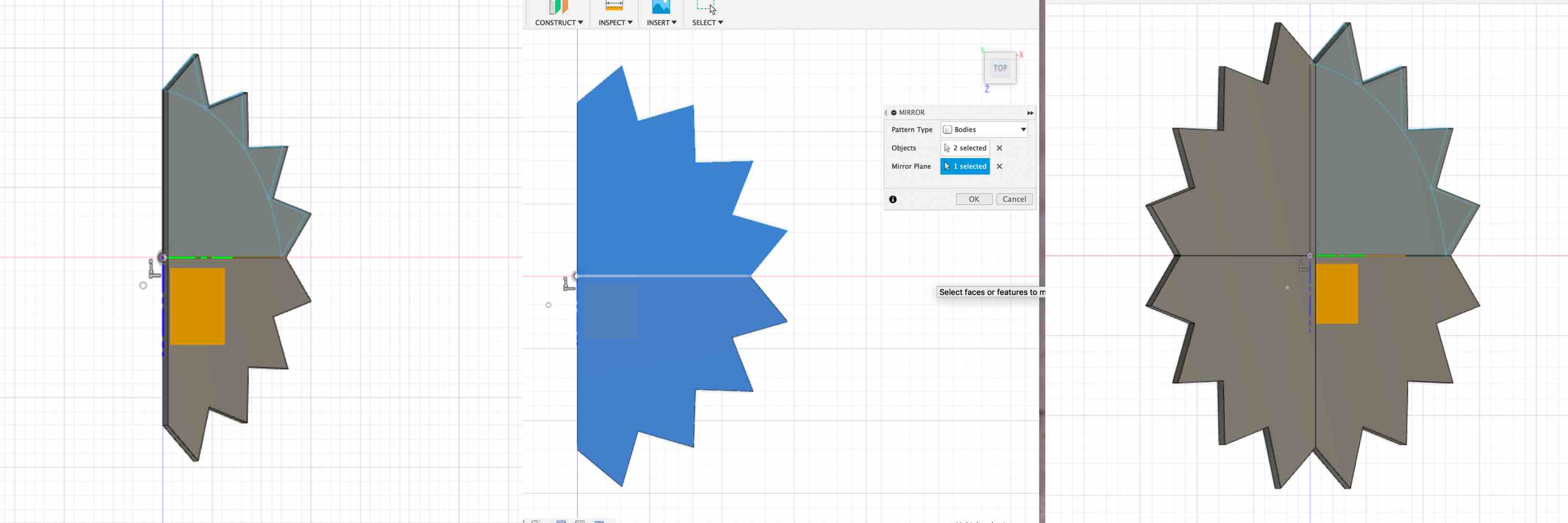
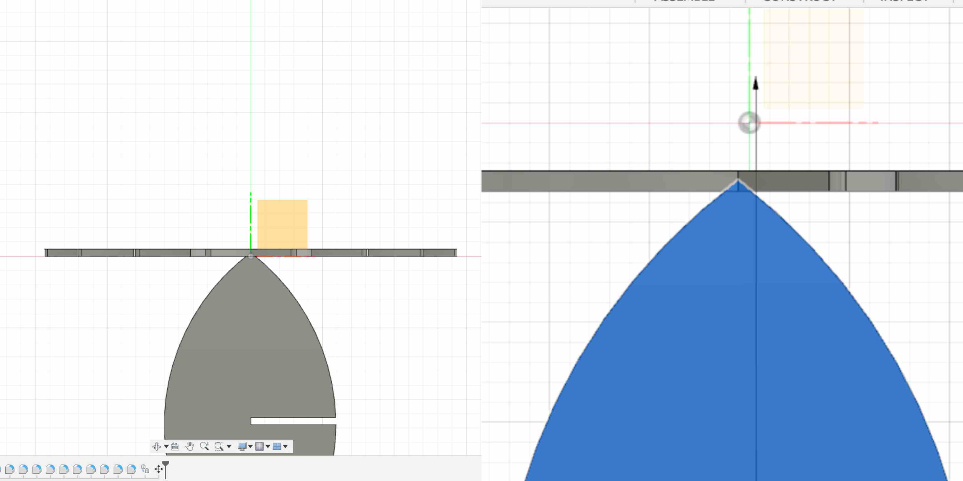
The final piece I saved for last because I believed it would be the hardest. However, by the time I reached this piece I realized it was just a combination of the pieces I had already created. As mentioned this table is meant to also be used in a child’s room. There for with the table set to the lower adjustment this can be placed in the room and used by the child to create crafts, work on, learn from and charge the final project Leaf Light. The top of the table will be engraved using a larger Epilog laser engraver with the many phases of the moon and how this is effected by the sun. I designed the top of the table to represent half a moon and half a sun. To start the construction of this piece I used the line tool with the two point arc tool to create a semi-circle.
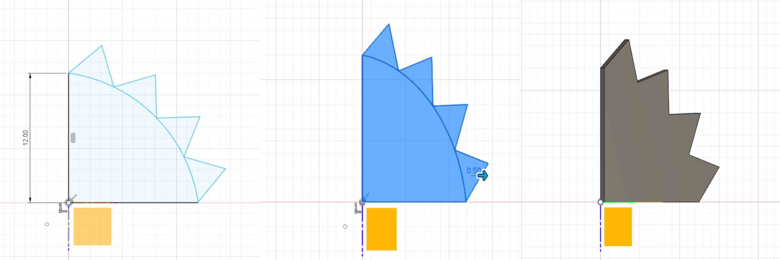
Using the same process as I did on the sun table top I created the rays. I used the same Ray Length Parameter as well to keep consistency. I created another semi-circle by copy, pasting and moving the previous semi-circle and lining it up to be centered. I repeated the ray length around the new half of the now circle.
Selecting the new faces of the rays I was able to use my hot key Q to extrude these the equivalent of the material thickness. With this completed my shape was made in just a few steps. I did have one complication referred to below.
This created all of my pieces, however it did not complete my modeling needs. I wanted to replicate, in my pieces, the accurately sized recess routed from each table top to leg connection. This will allow the connections to have a .25” fit and be further stabilized.
In order to create this representation I had to copy and move a variety of pieces all into one working layer. I decided to use my table top layers as the main working layer. This is decided based on the fact that I want to be removing the incoming pieces from the table top to create this recess.
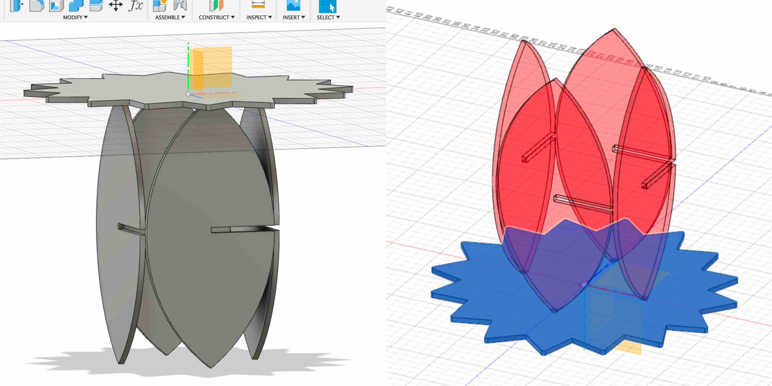
I brought the leaf leg copy into the sun table top layer. I placed it so that the pieces would intersect with a .25” fit. I adjusted the pieces to represent the correct structure. I then copied and moved a new leaf leg body and aligned it across from the first. This distance represented the shelf length of 12”.
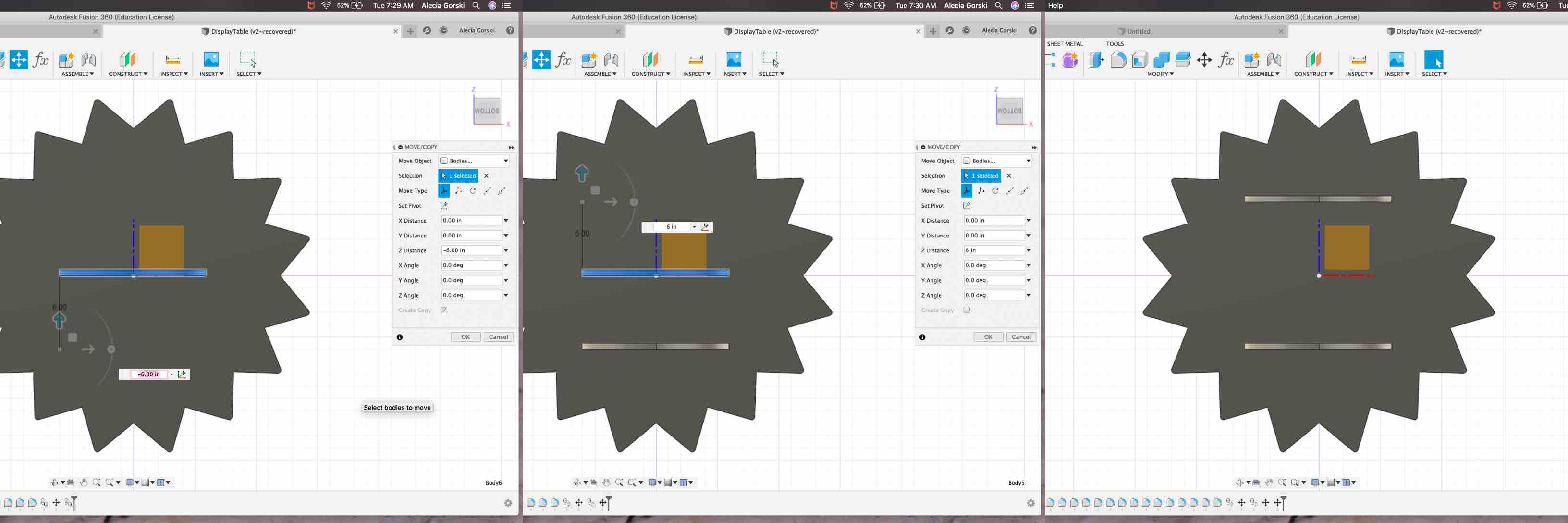
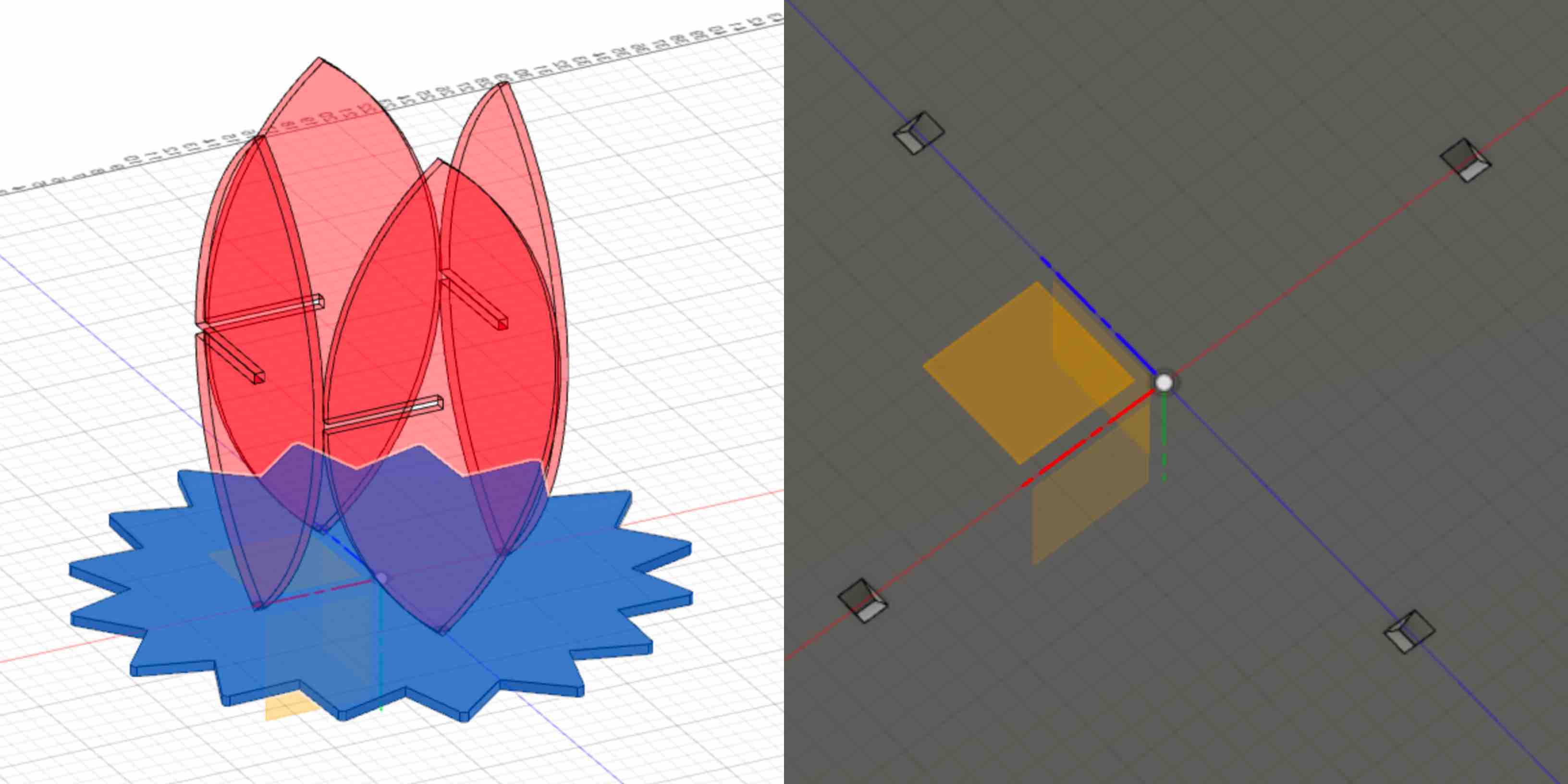
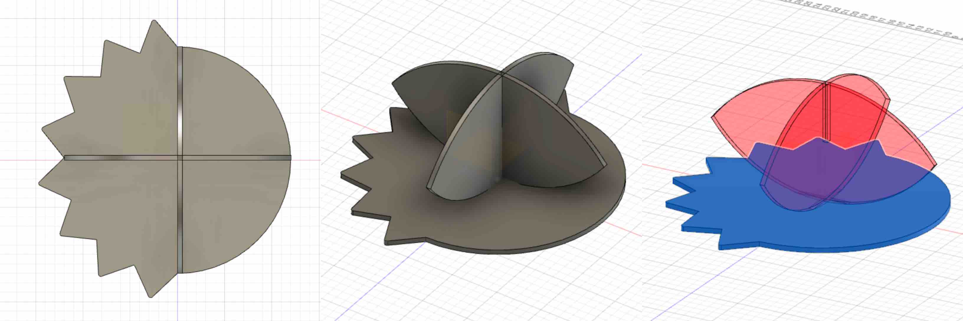
I continued the process of copy, pasting and moving each leg into the correct orientation. When I was satisfied with the model representation I was able to use the Combine tool to create the cut out recess. In the cut settings listed below there are three main selection that should be adjusted. The first is the Target Body. In the reference photo you can see that there is only one item selected as the Target Body. This is the table top that is represented in blue.
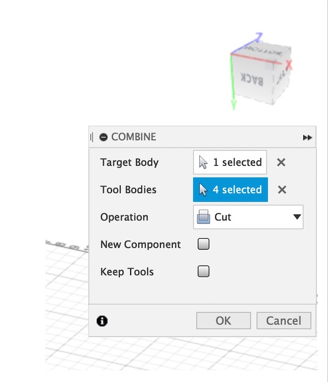
The second option that should be adjusted will be the Tool Bodies. These are the reference bodies and are represented in red. As mention above the leaf legs were placed into the working table top layer because they were more of a representation on the effect being made in the recess of the table top. With the third option being the Operation, in this case we are removing the leaf leg shapes from the sun table top to create the recess, the Cut command was chosen.
Once complete the recess was created and placed directly into the table top model. This was then used to determine the measurements needed for the size and placement of the recess when transfered into the CNC software Aspire.
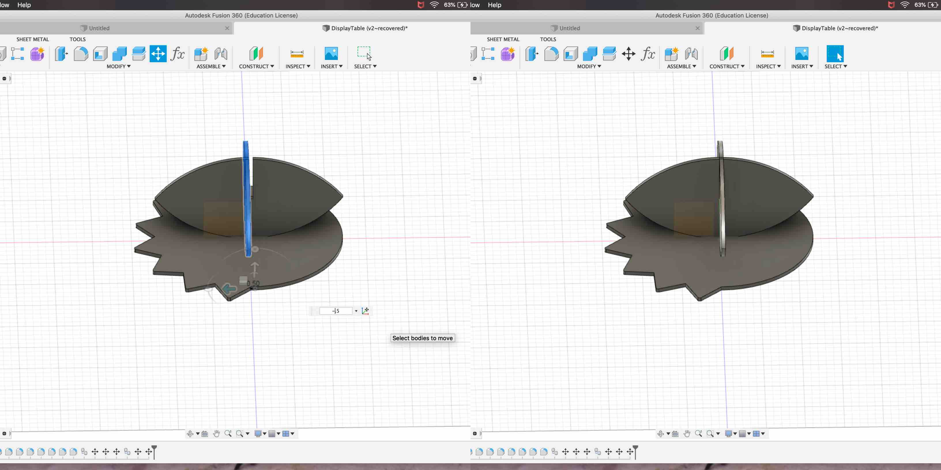
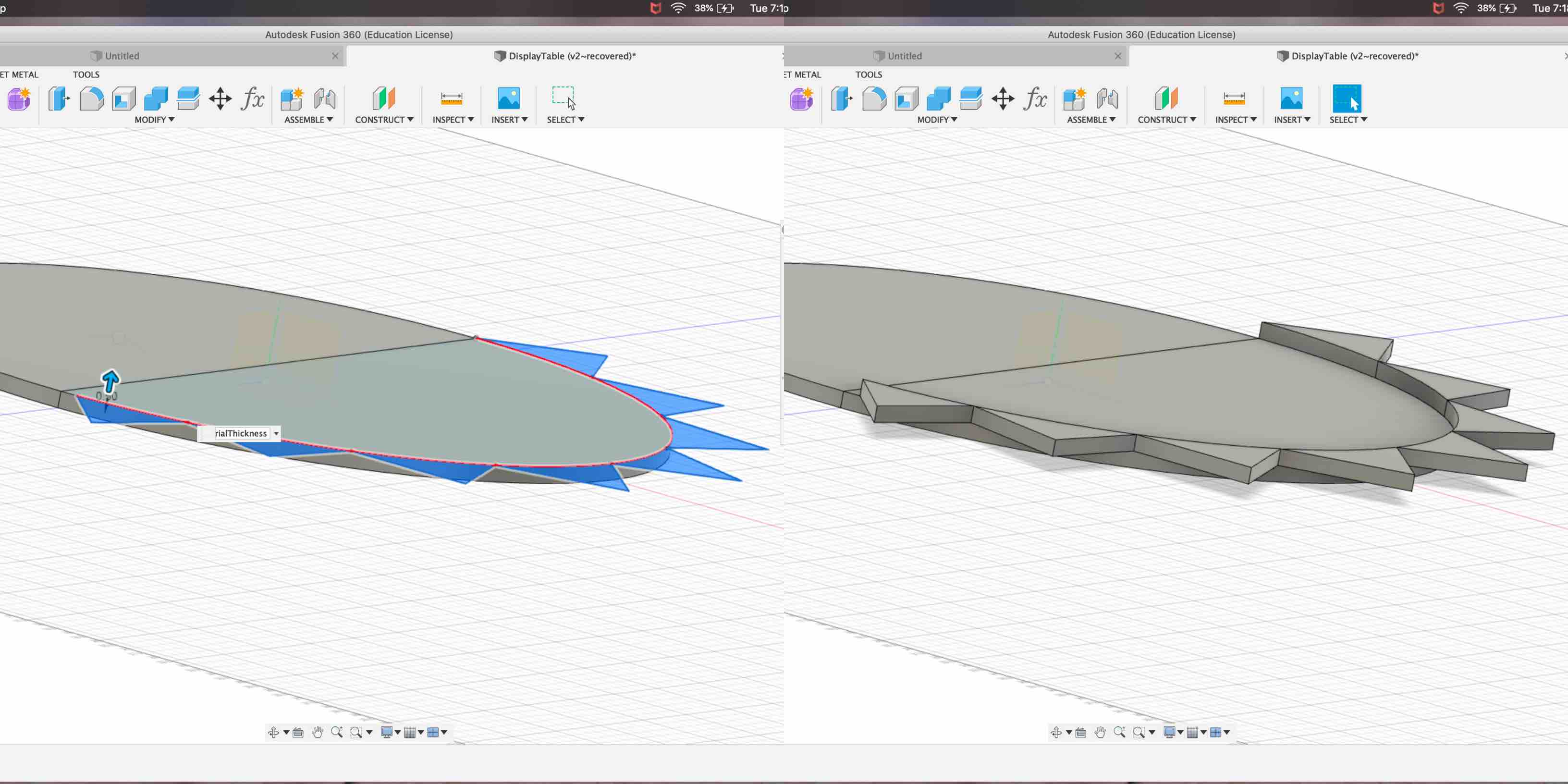
With the process proving successful I moved on to creating the same representation in the table top for the shorter installation. To do this I again brought in the leaf shape and placed it on the half moon and half sun table top working layer.
This was then lined up to be centered. This is important. The leaf legs were designed to intersect in the center of the modeled top. This is to ensure maximum stability.
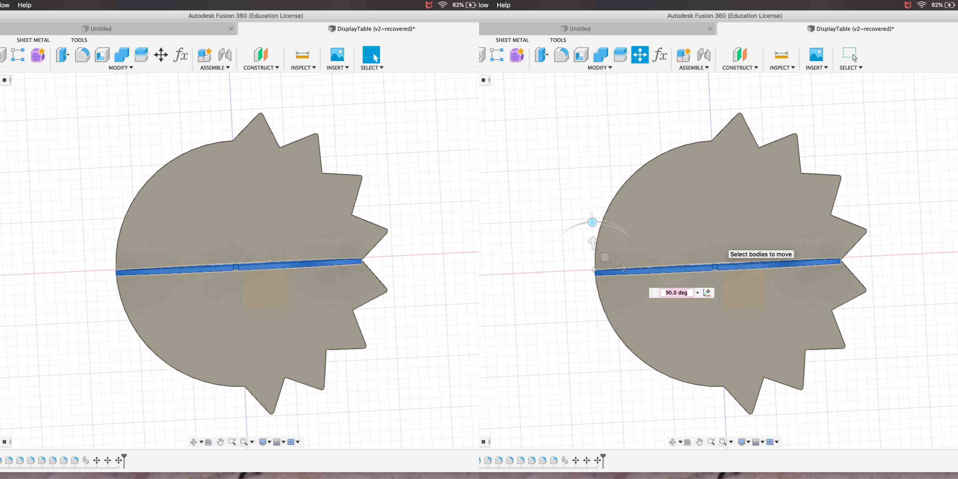
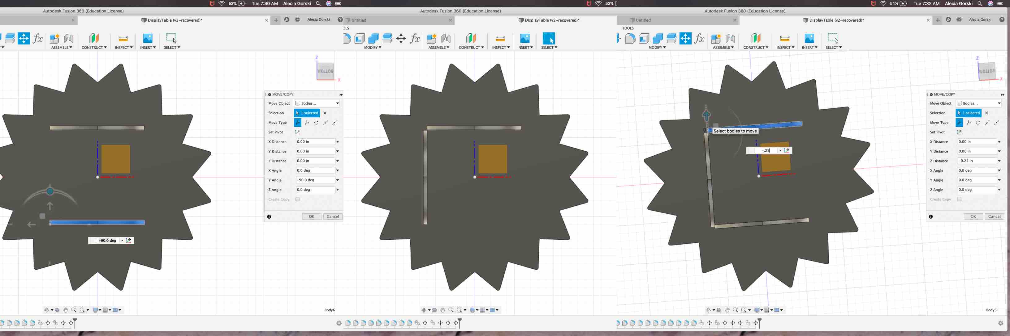
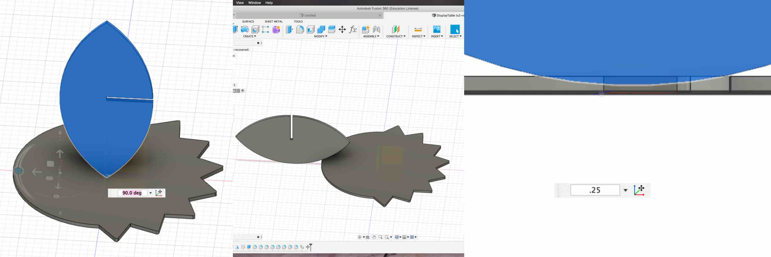
I duplicated this shape and rotated it to represent the intersection. I then used the move tool to line the pieces up by the crossing tabs.
When viewed from the top a perfect intersection was shown and I knew my placement was right where I wanted it to be place. I then stepped through the same cutting process. I chose the Target Body, represented in blue, to be the table top the intersection would effect. I chose the Tool Bodies, represented in red, to be the leaf legs. The leaf legs were then combined with the cut tool. This again created a perfect representation to be measured and applied into the Aspire file.
This completed the modeling steps taken to create this Something Big!
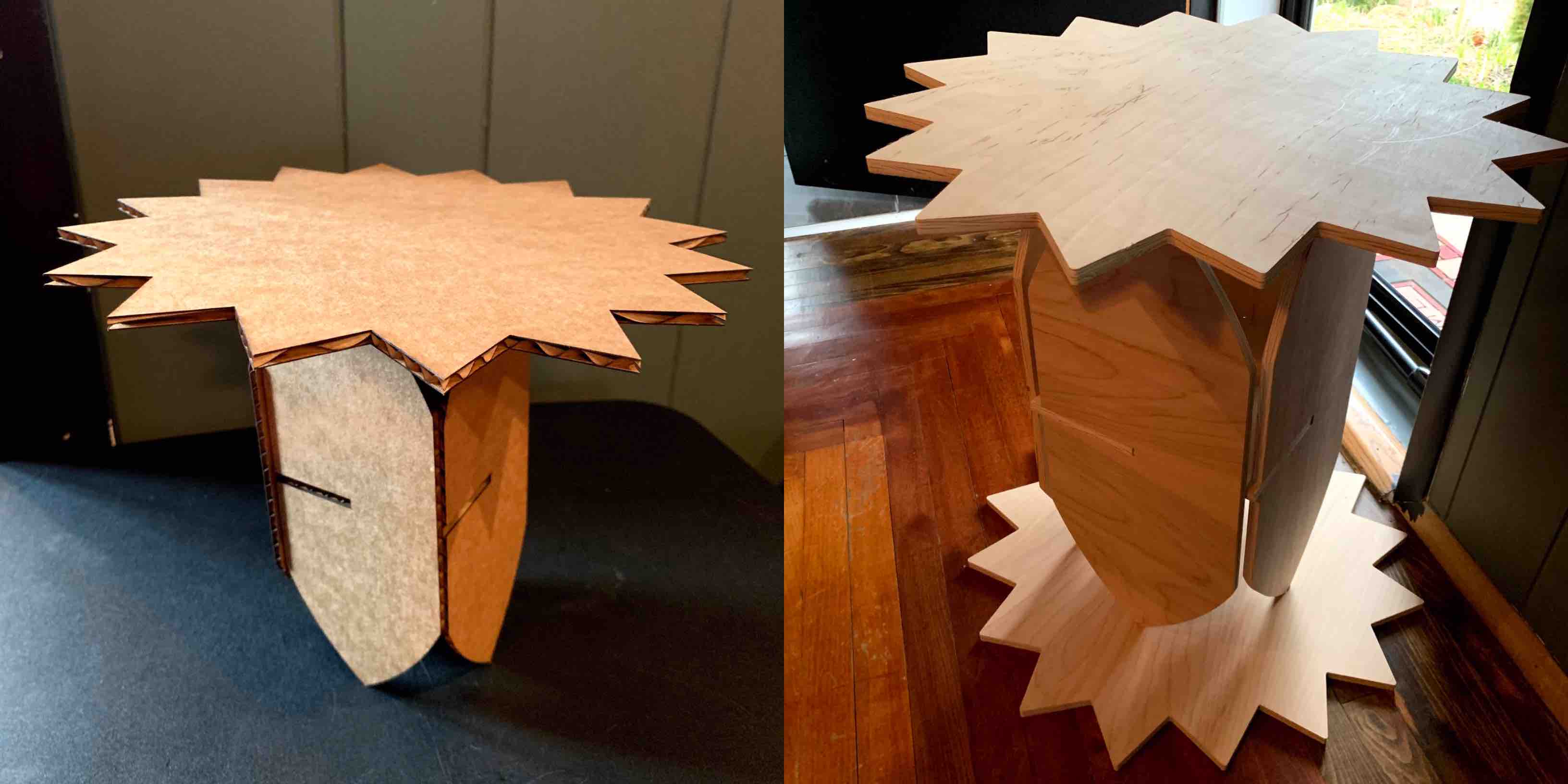
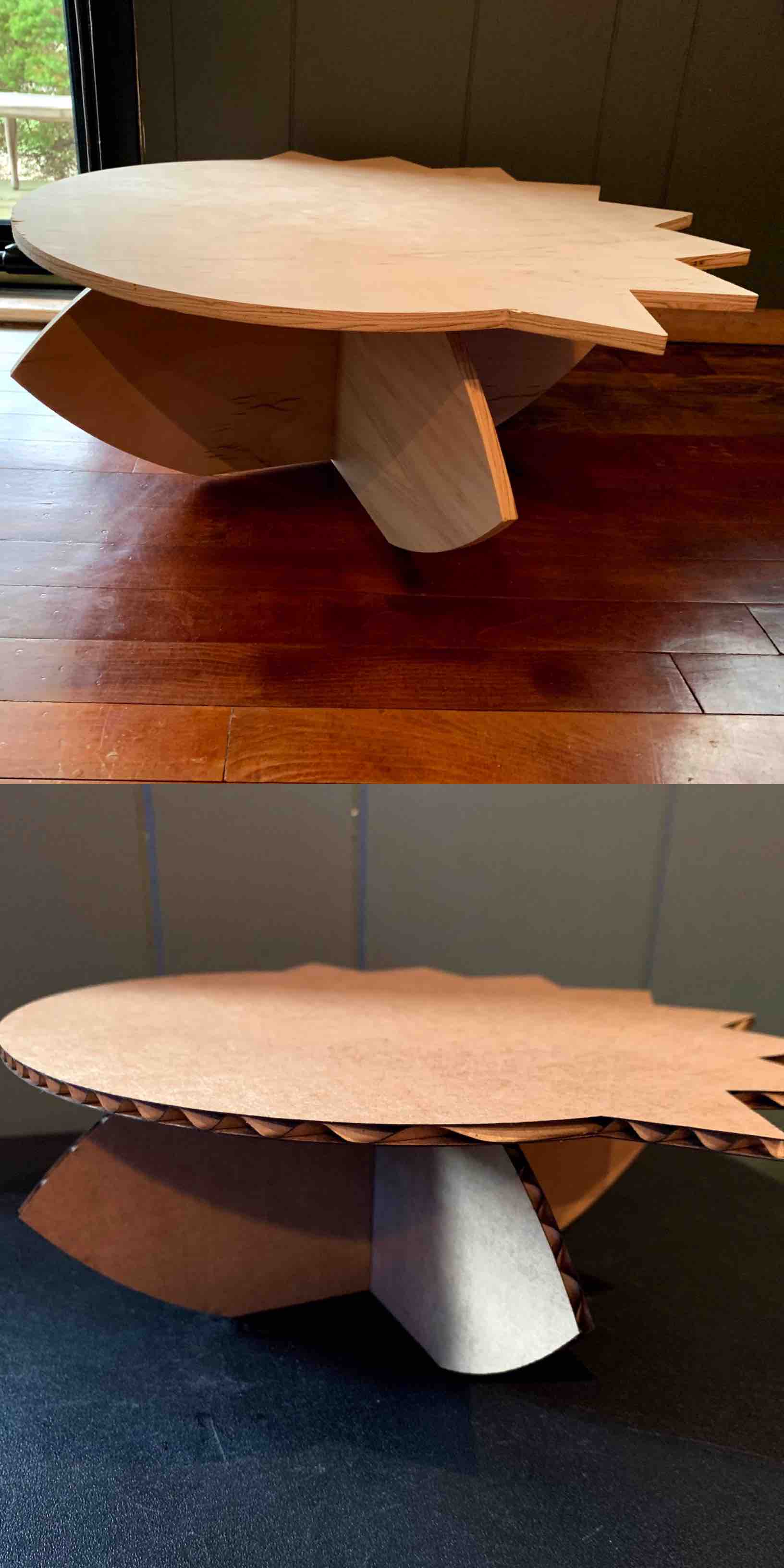
Cardboard Test
My next step was to create accurately scaled down models of each of these designs in cardboard. This step is important to work out any potential issues on a small scale first in order to reserve materials and reduce waste. I scaled the .5” thickness of my wood to the .17” of thickness to represent my cardboard. With the scale in material thickness came a percentage scale in all other associated sides. The equation was .17/.5 = 0.34, then 0.34 x 100 = 34. The 34 represented the final scaled size to hold a parametric scaling.
I then used CorelDraw to import my .dxf files that were saved from each of my sketches in Fusion 360. As these were imported into CorelDraw the size was an accurate representation in inches. I selected each of my imported pieces and individually scaled them down by 66%. There were now the correct scale to represent how my pieces would come together. I nested each piece to the correct location on the cardboard layout in order to save as much room as I could.
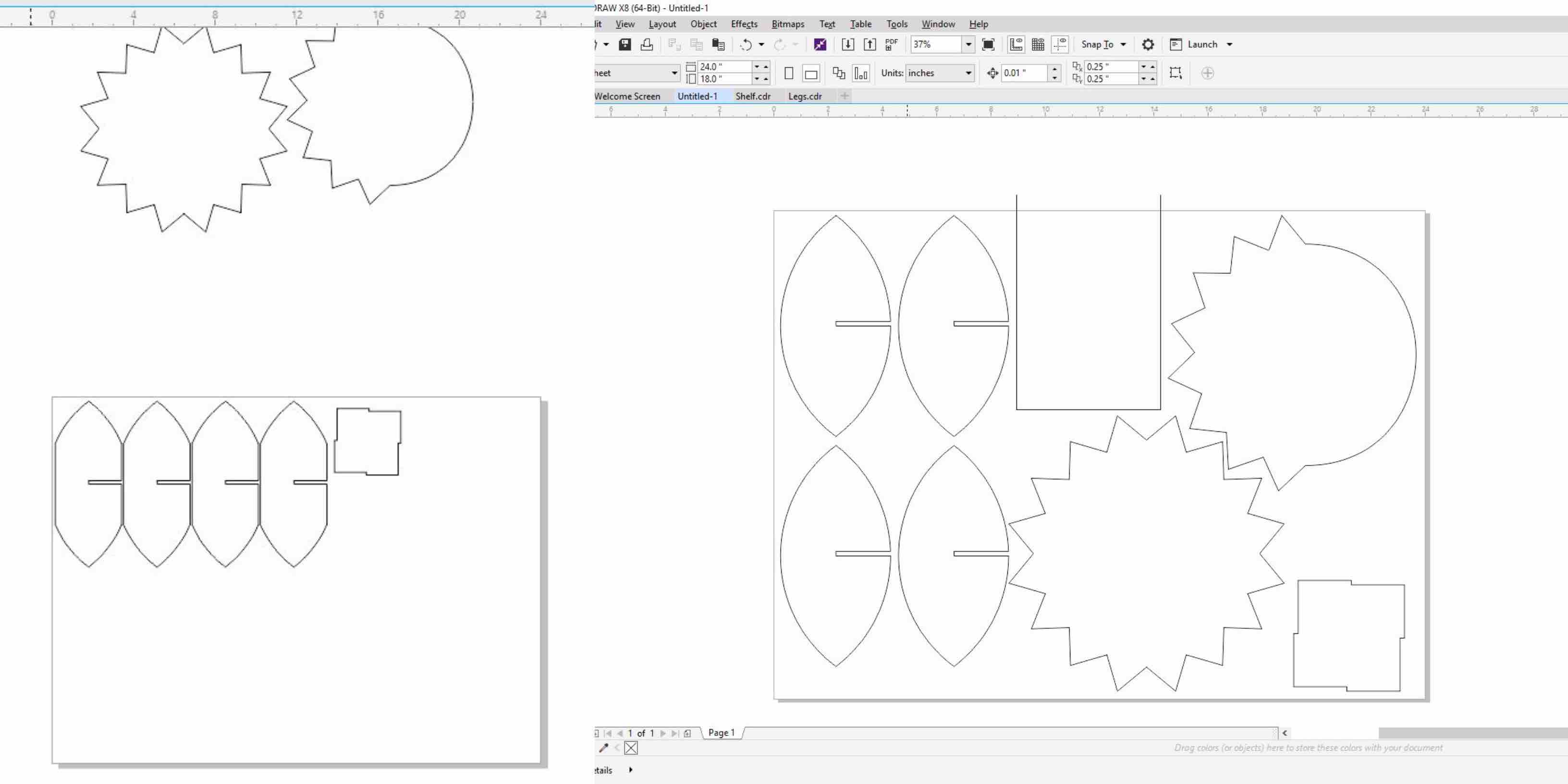
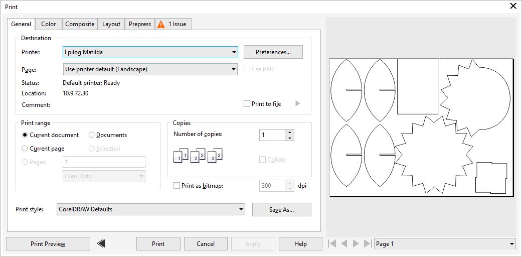
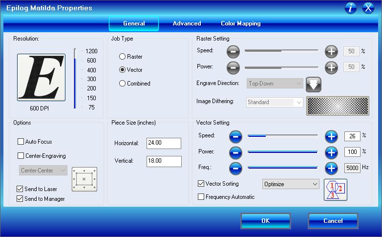
When each of my pieces is placed where I need it and every line is a hairline it is ready to chose the settings for the print driver. When in the CorelDraw layout go to file and then choose print. This will provide a gray screen with options for which printer you would like to use. In this case I was using Matilda, our 24”x18” Epilog laser. Once Epilog Matilda is selected I chose the Preferences tab to the left of the printer name.
This prompted a blue screen with more settings. As explained in week 3 I set the material size and chose to Vector cut only. There were no needed raster job. I set the power, speed and frequency for Vector only job type. With my settings filled in for cardboard I sent my job to the printer.
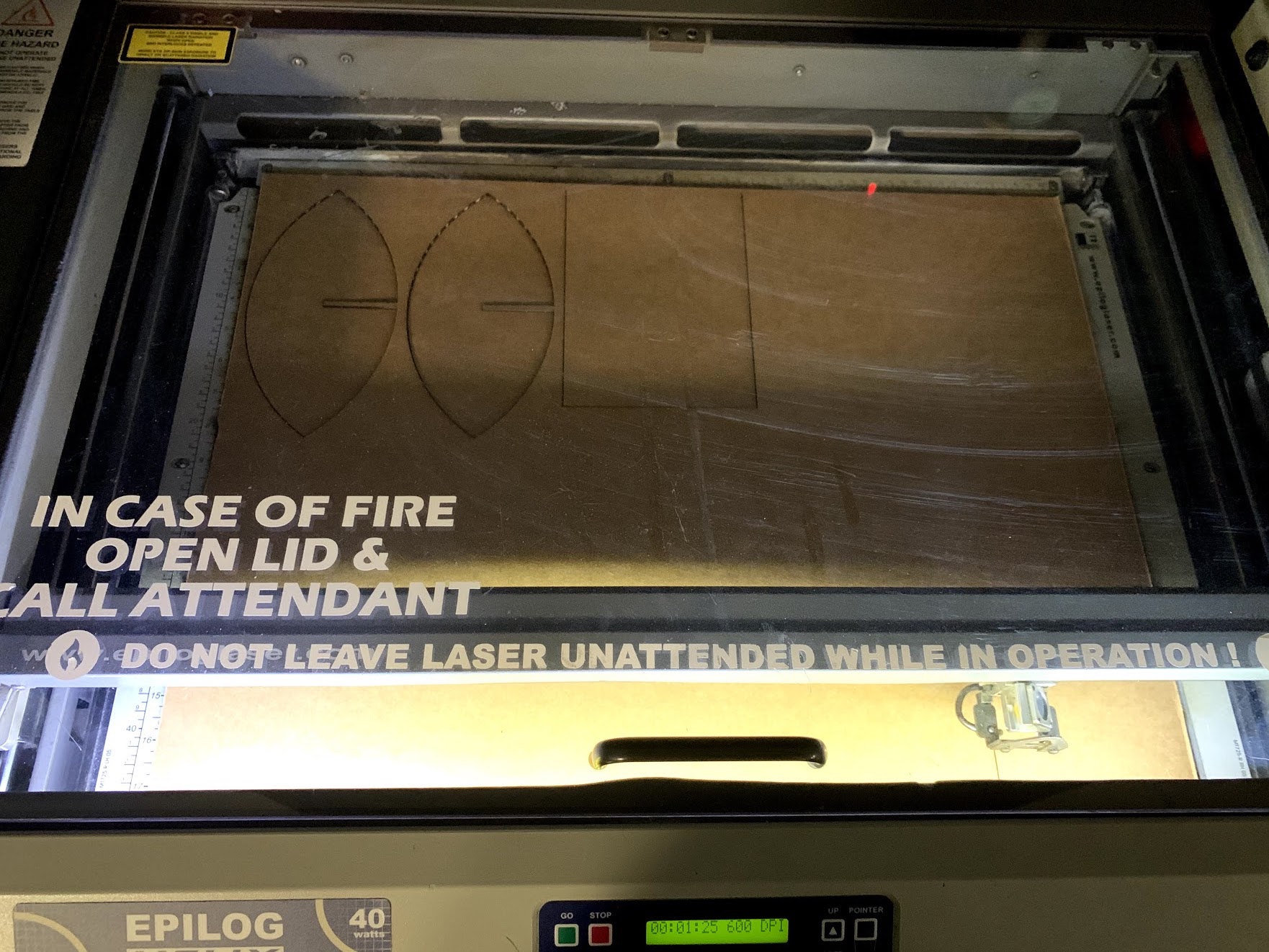
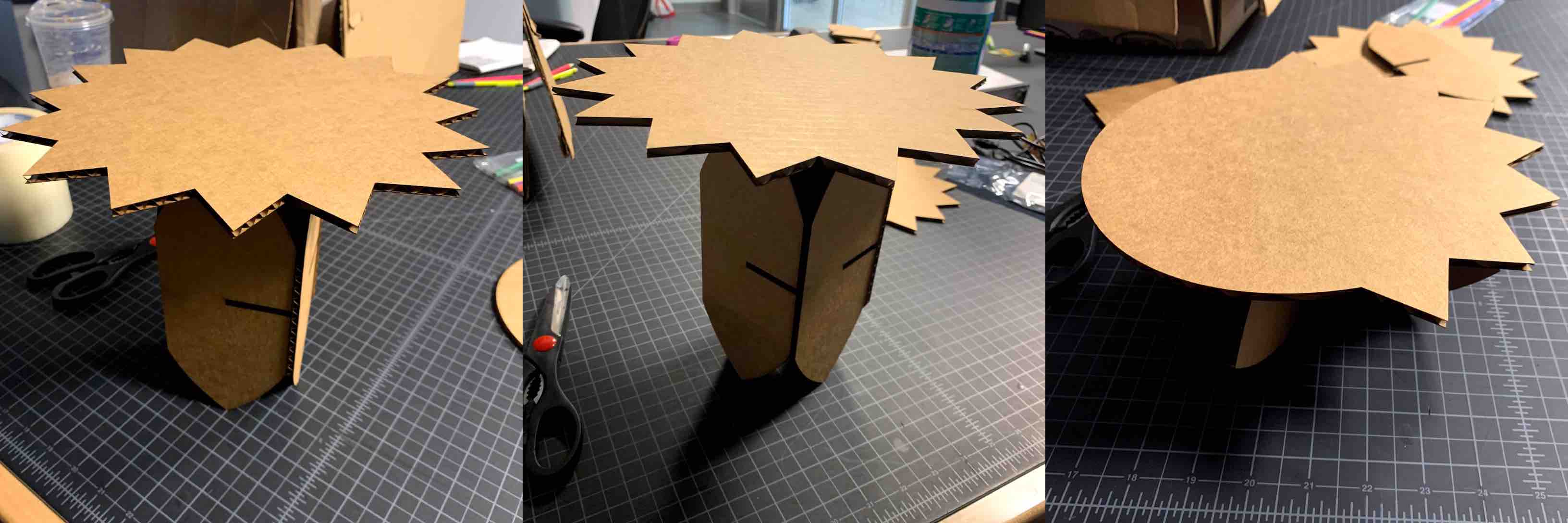
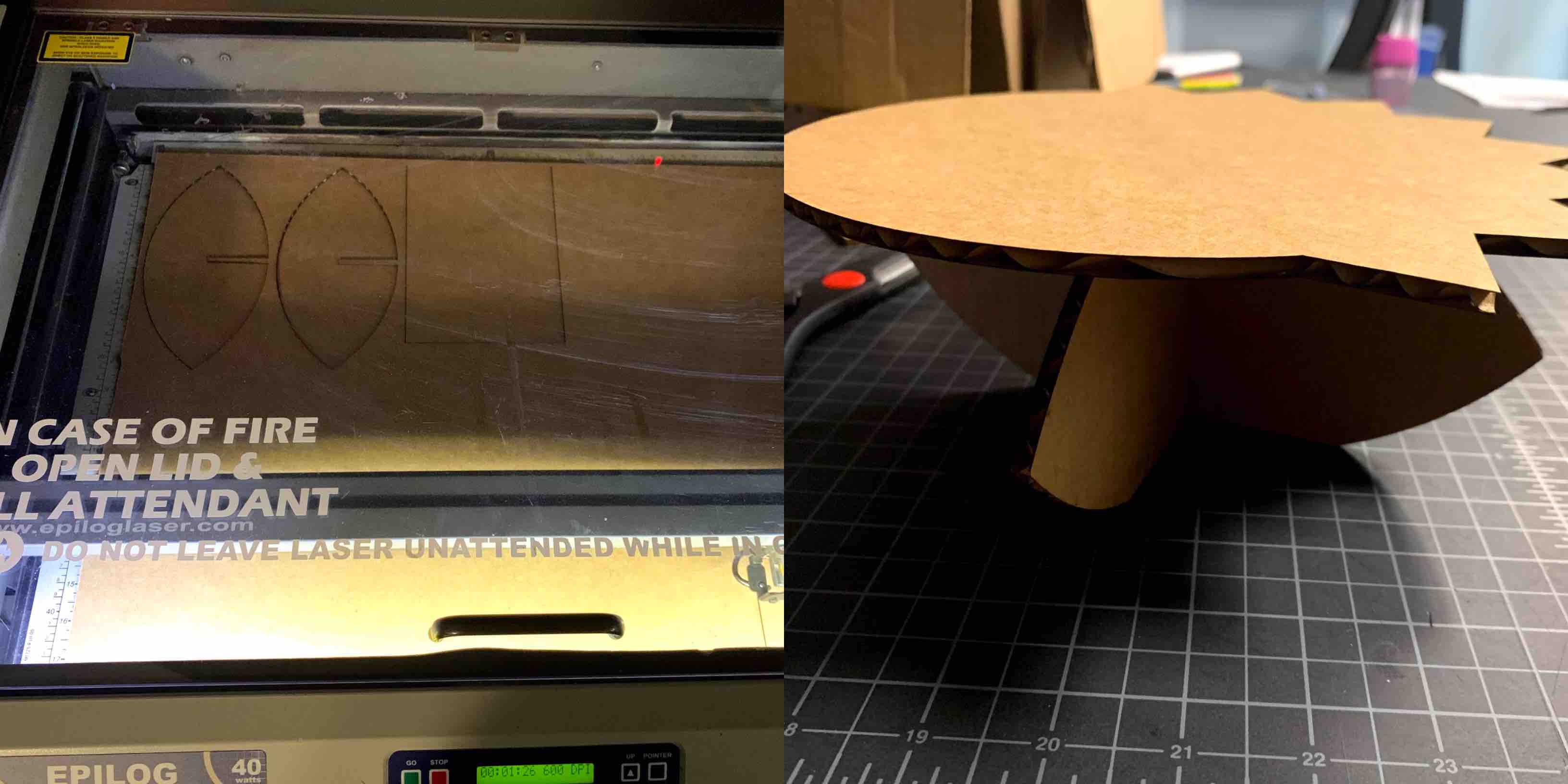
With the laser running and my settings in, it was a smooth cut. I was able to safely complete the job and remove my pieces from the bed of the printer. When assembled the tall representation worked great, however I ran into some complications with the smaller representation. This is discussed in more detail below.
Once the complication was fixed and the leaf edges now had a solid edge to stabilize the structure I was satisfied with my design. My cardboard test now a pass I was ready to being with the CNC ShopBot and the Aspire software.
CNC
Aspire
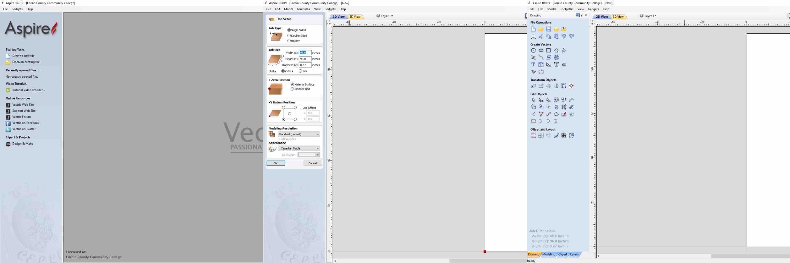
The first stage to using the CNC router is to create the Aspire CAD file that will communicate correctly with the machine. I opened the Aspire program and chose to create a new file. This prompted options on the left hand tool bar to set you material settings. This is where you specify the use of a 4 foot by 8 foot half inch material.
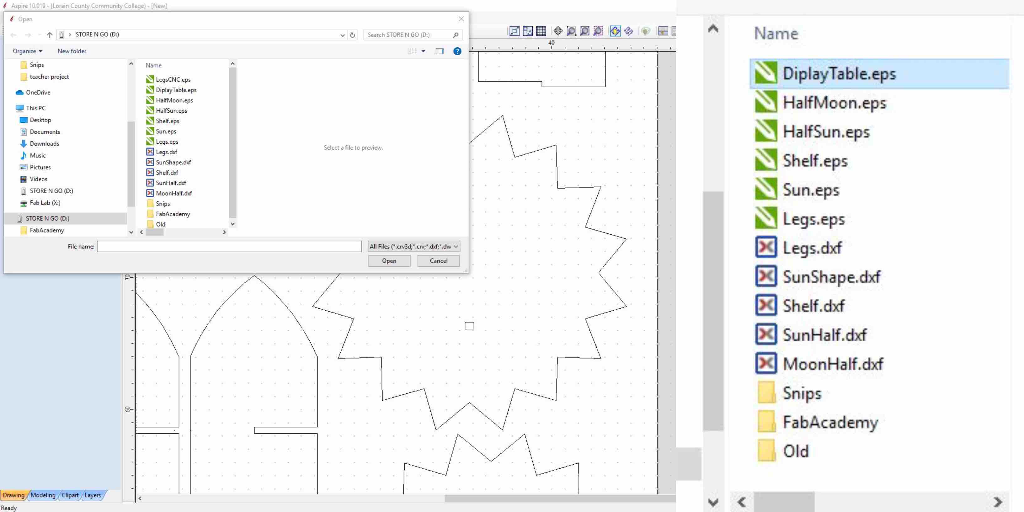
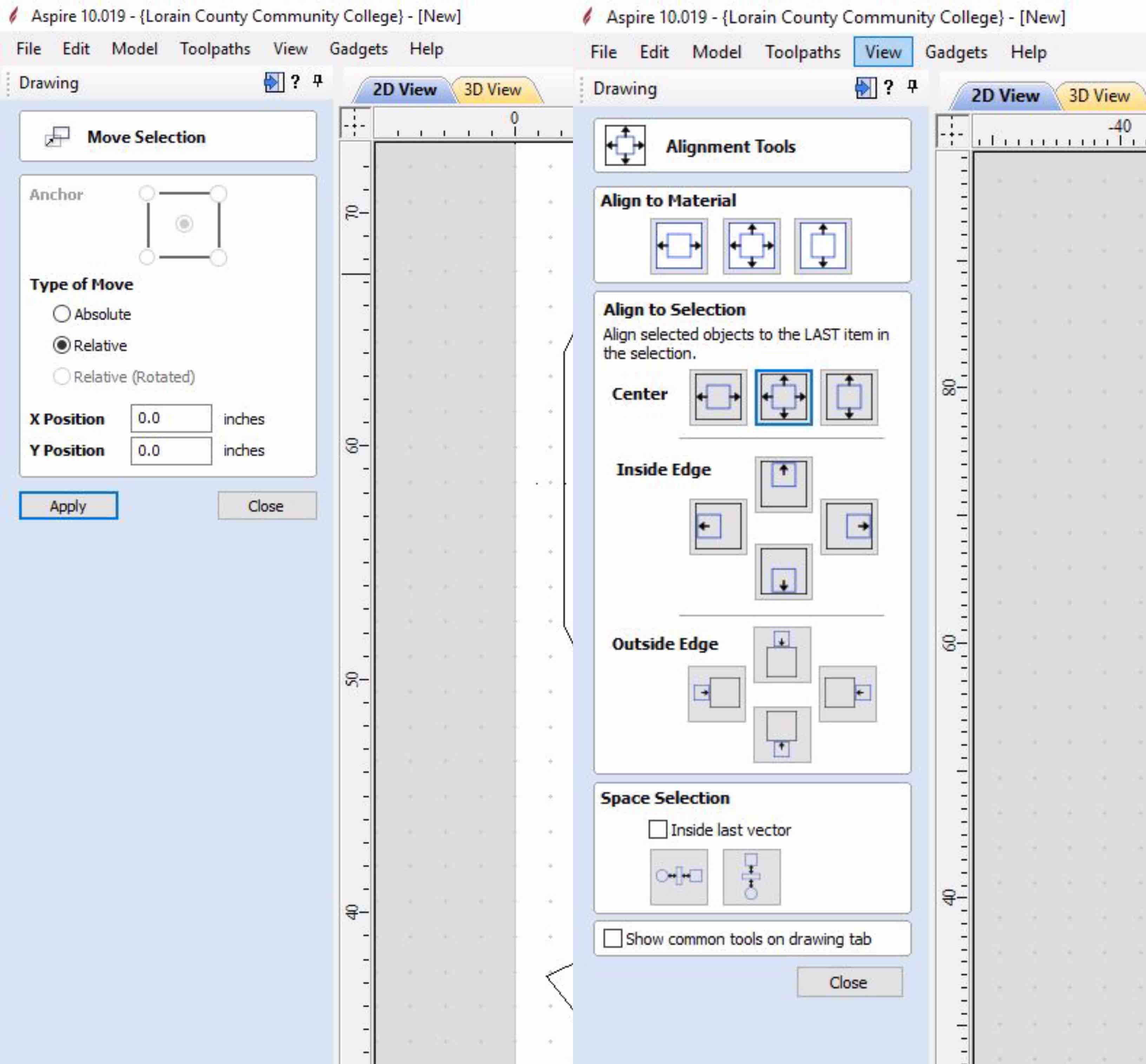
The next step is to import my files. I saved each piece as a separate .esp file. These I imported one at a time by going to the top left corner of the program and selecting file. I chose open and selected my file. Once each file was opened into my document I was able to begin checking my files for integrity. I used the square tool located in the left hand tool bar to create my recess routing squares the correct size. Using the move selection tool I placed the fist routed representation based on the measurements form Fusion 360. Using the align tool helped to easily place the pieces specific measurements apart. I used this process to create each of the routing recesses added for stability.
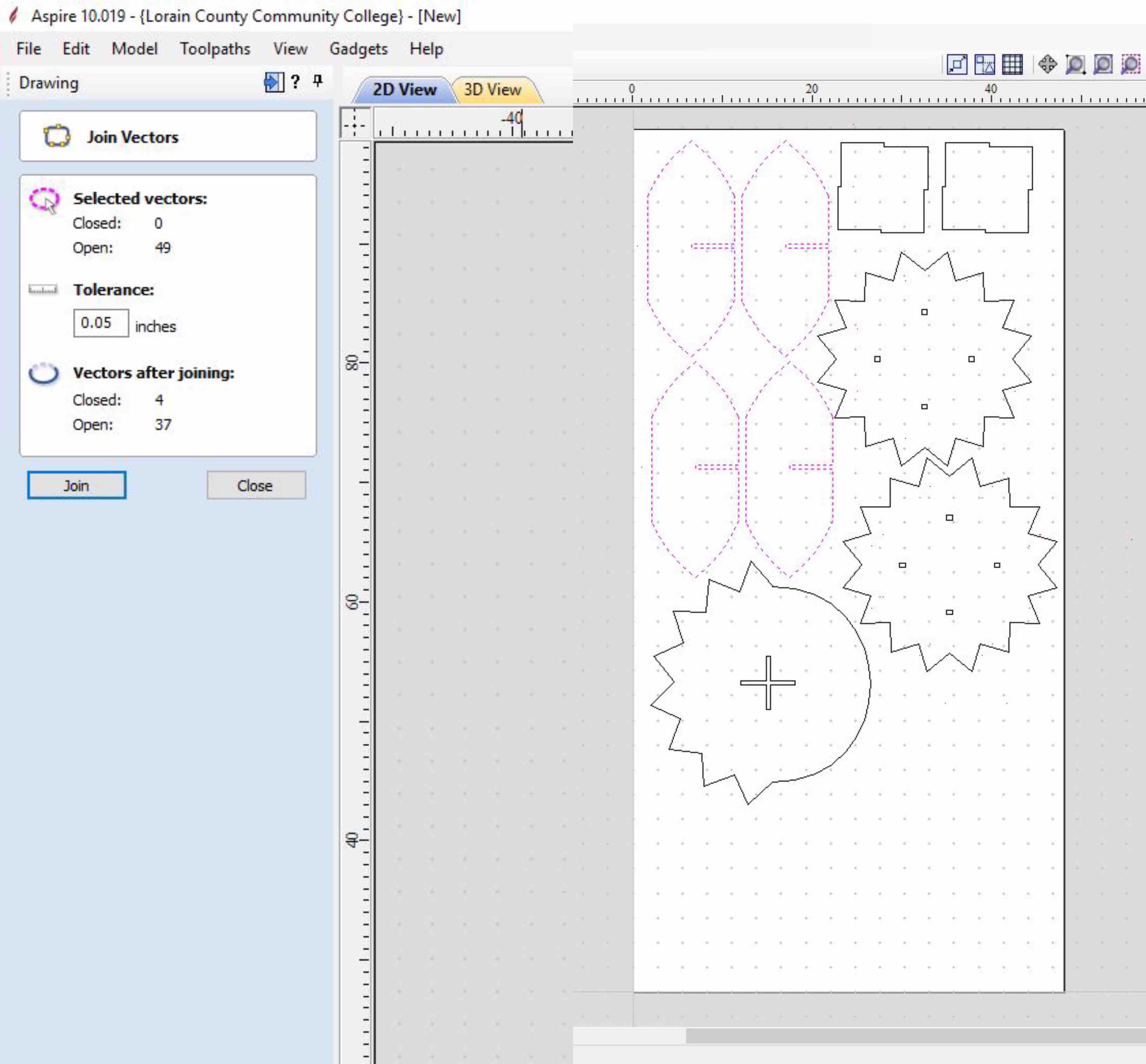
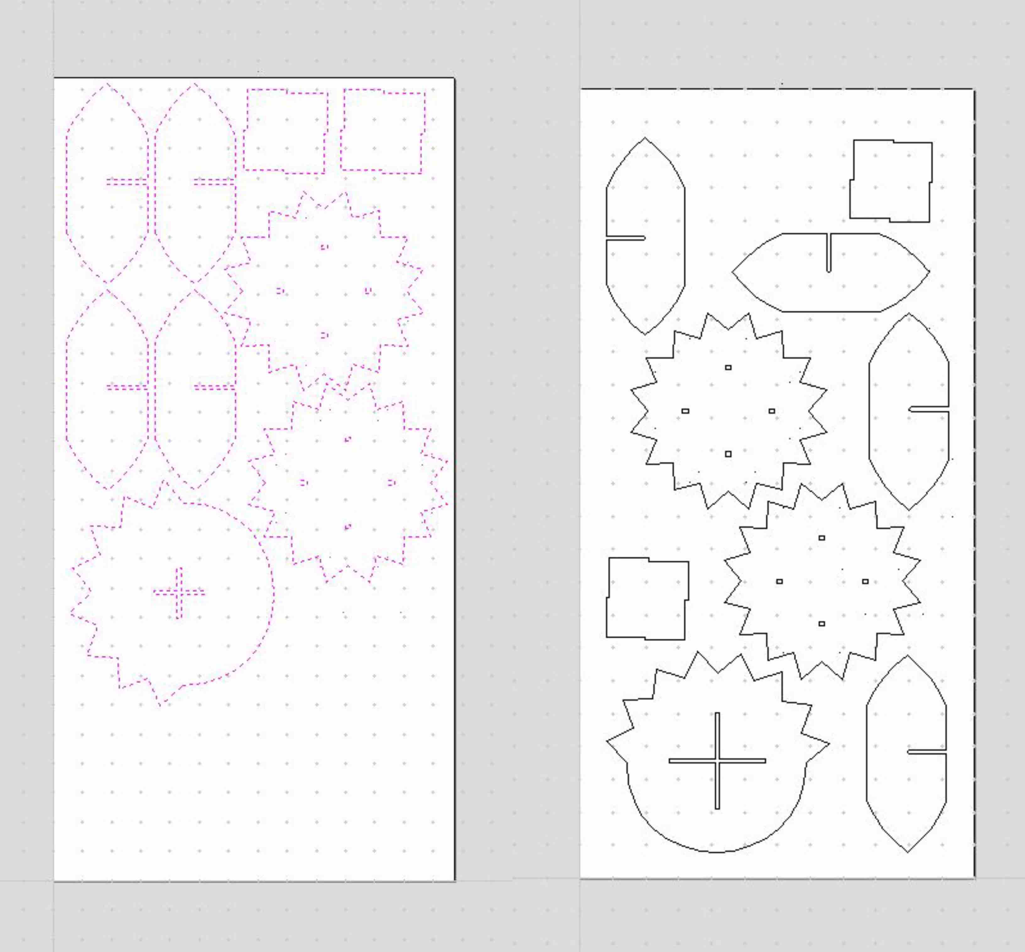
The integrity of the file is what helps to keep a smooth routing. TO do this the file must be checked for open vectors. This means that the shapes you are cutting are not completed and connected. When checked my leaf legs appeared to be open. This was represented based on the purple color the lines took. I used the Join Vectors in the Drawing tool bar. This closed the necessary vectors and I was able to move on in the process.
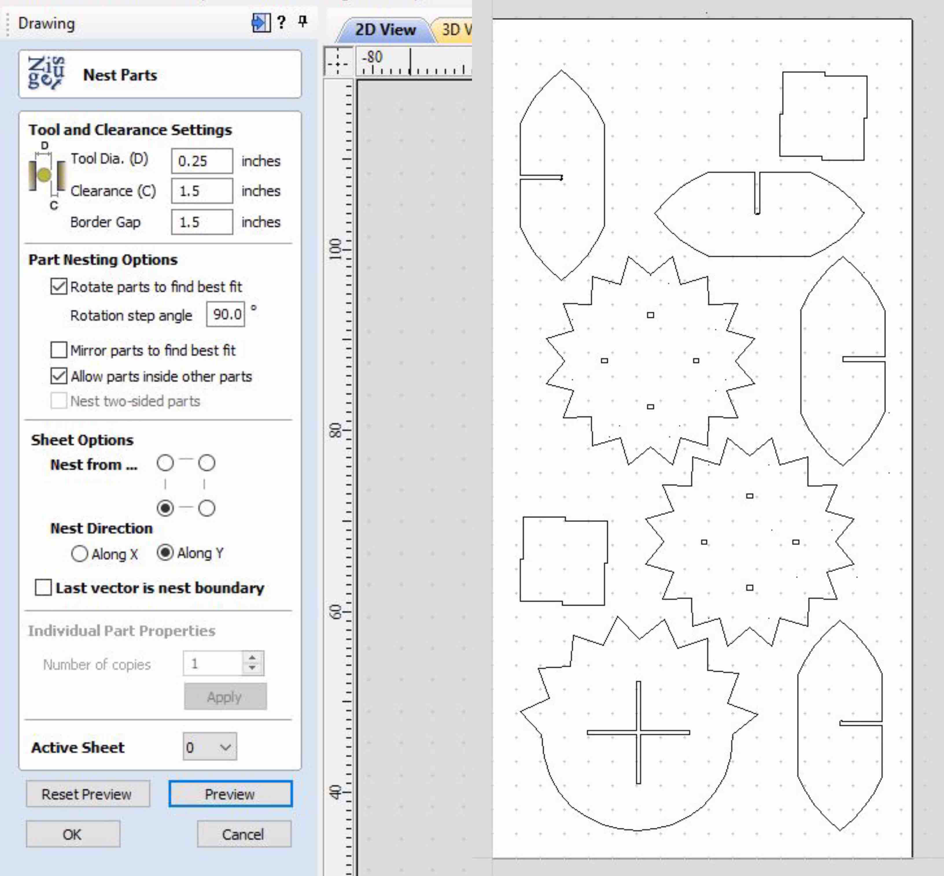
With the vectors closed I selected all of the shaped and used the nesting tool. This is in the left hand tool bar, represented by an square icon make of jumbled letters. This then best fit my pieces to a few design rules. These include leaving 1.5” clearance between each piece, as well as the surrounding edges. The tool Diameter is also set to represent to .25” bit I planned to use.
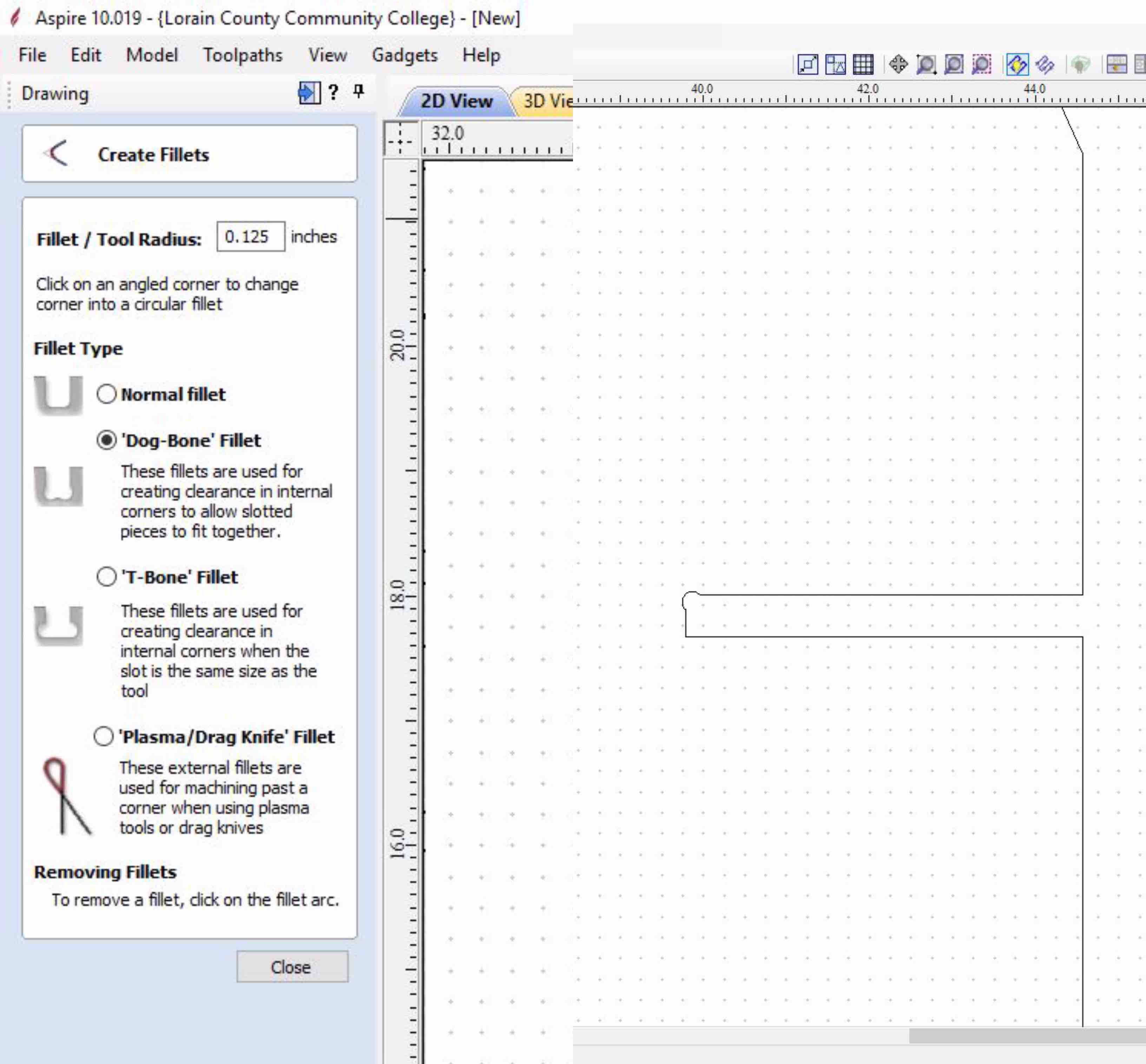
When the nesting is complete and all components are placed correctly there are a few additional editing steps that need to take place. To help the tabs and slots to fit smoothly together there are a few Fillet Types that can be applied. On the group test page there is reference to a test that showed dog bones worked smoother with this material and it respective thickness. I chose a radius of .125, the dog-bone fillet and selected the corner of the slot where I wanted to apply the change. It then added a circular indent in the edge of the slot fit. I did this to each slot edge to improve the functionality and fit of each piece.
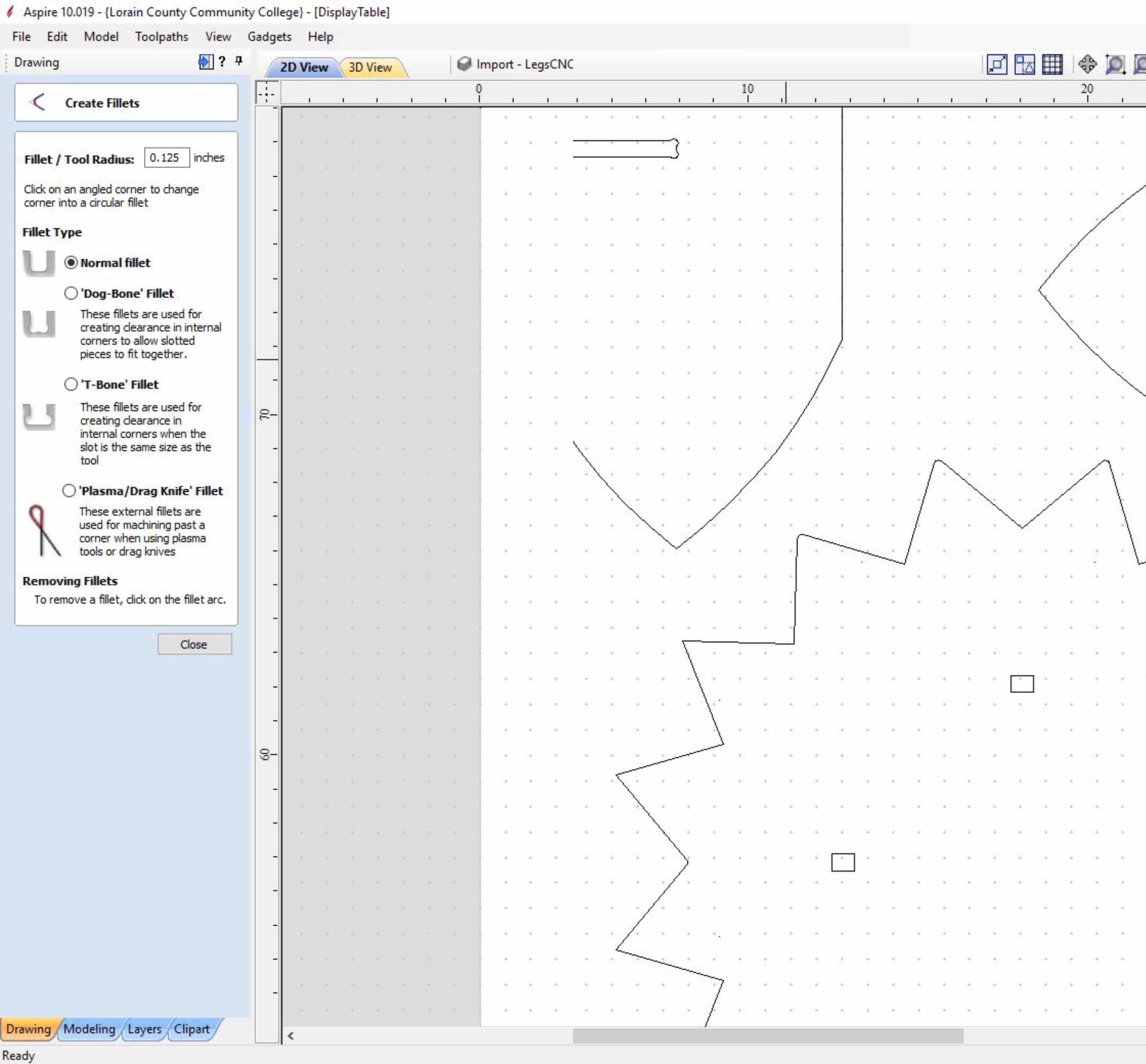
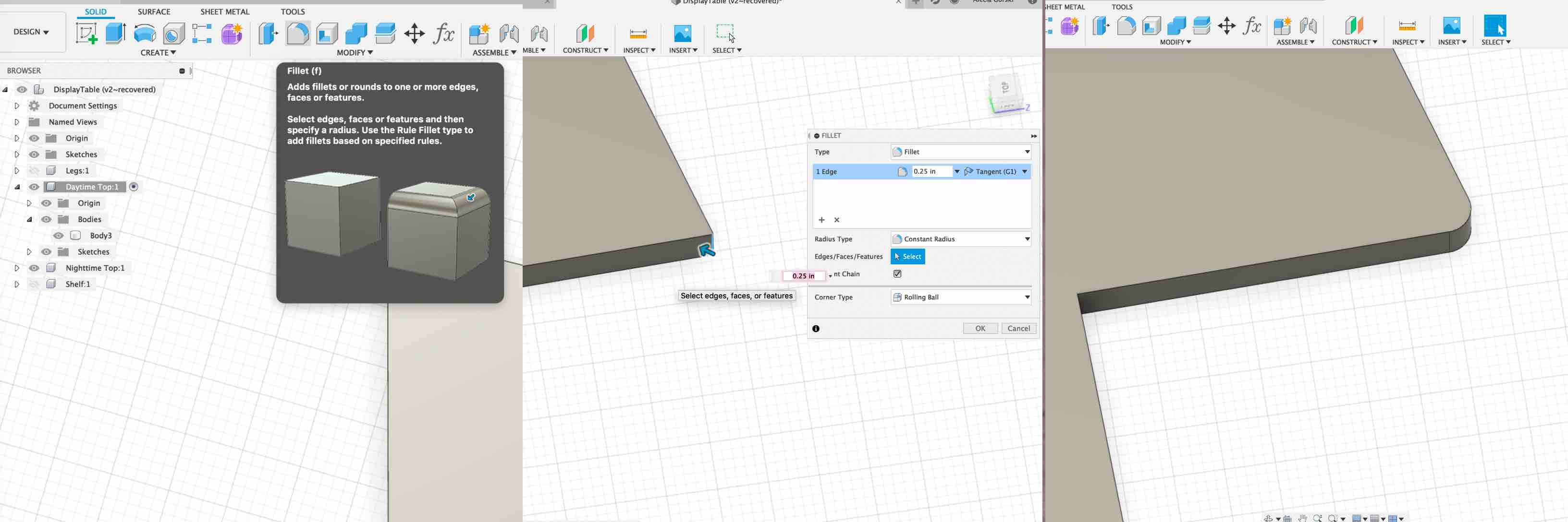
The other way I used the Fillet tool was to round the edged of my sun table tops. This was mentioned previously as an attempted fix in Fusion 360 and discussed in more detail in the complications listed below. In Aspire it was very simple to apply the change of sharp to curved edges. To do this select the Fillet Tool from the left hand tool bar. This time I used the Normal Fillet option. I chose the point I wanted to round and the Fillet Tool does all the work.
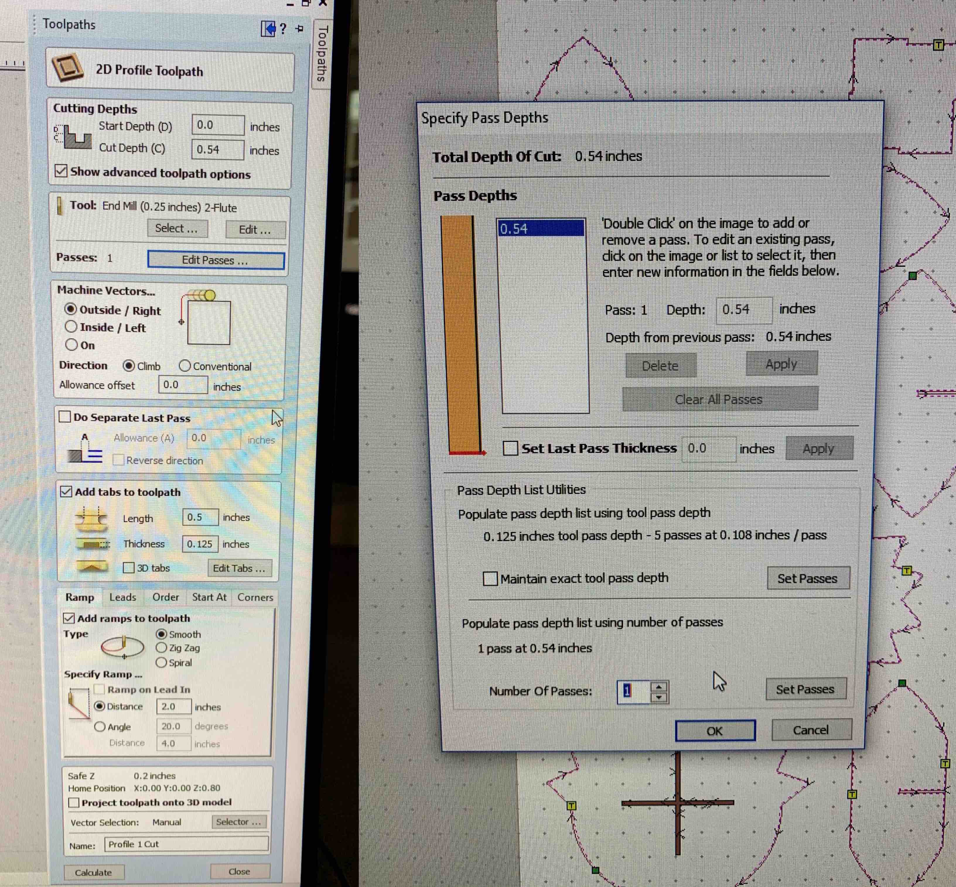
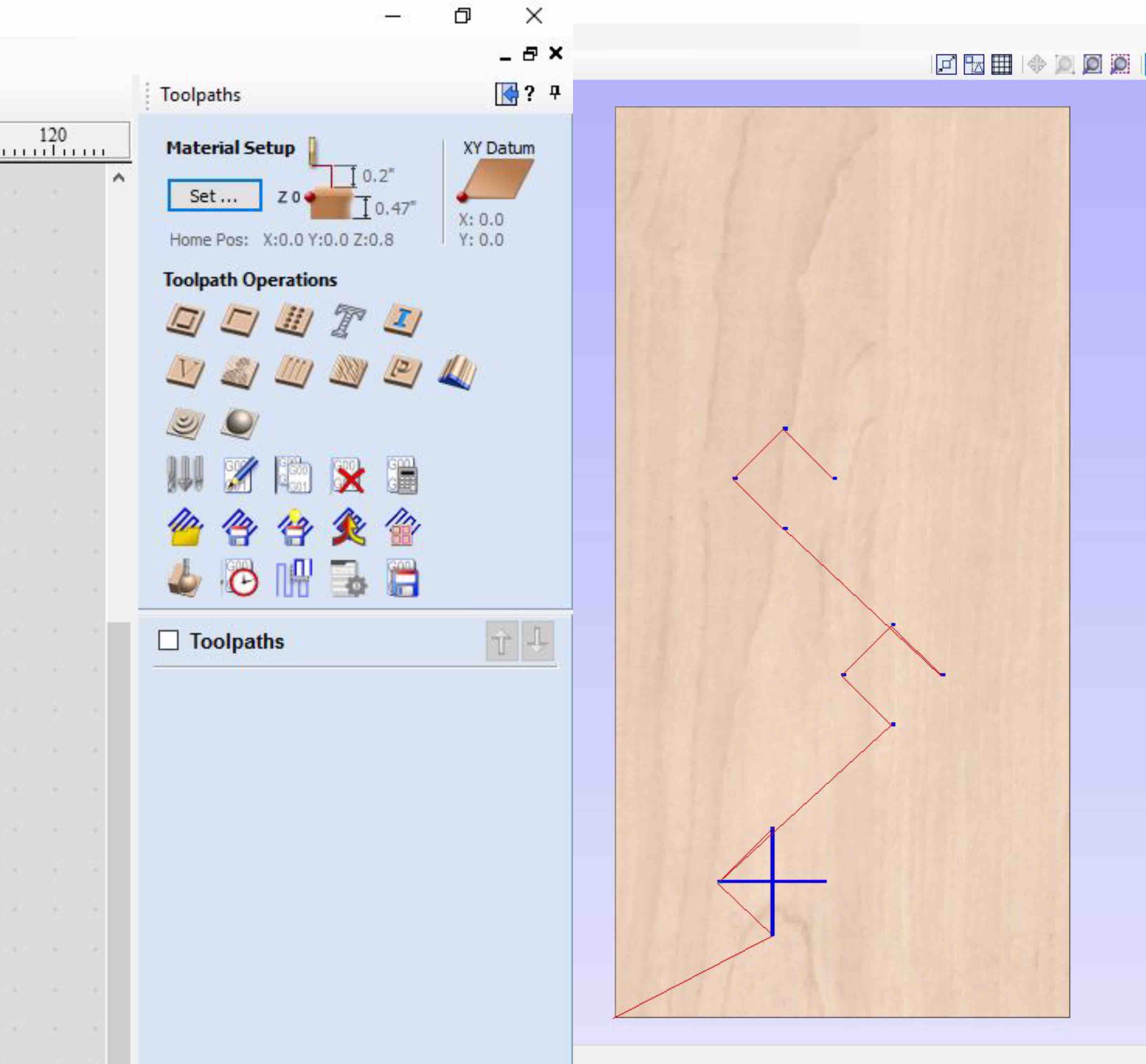
With the design complete, checked for integrity and nested correctly I defined my toolpaths. This is a really important part of the process. This is the point you communicate with the machine the paths you want it to cut. This is how your pieces are created. My design had two toolpaths so was sure to assign each with the correct style. In the Toolpath Profile the start and cut depths are defined, the end mill used is defined, the vector path is defined, as well as the tabs in toolpath and ramps. The corresponding values are listed in the depiction attached.
Tabs are an important tool to keep in mind. As an alternative to screwing each piece down as well as the surrounding loose material, tabs can be added. This keeps small connections in selected areas where each piece will still be connected to the overall sheet. This is the style I chose to use. I applied a varying number of tabs strategically into the tool paths.
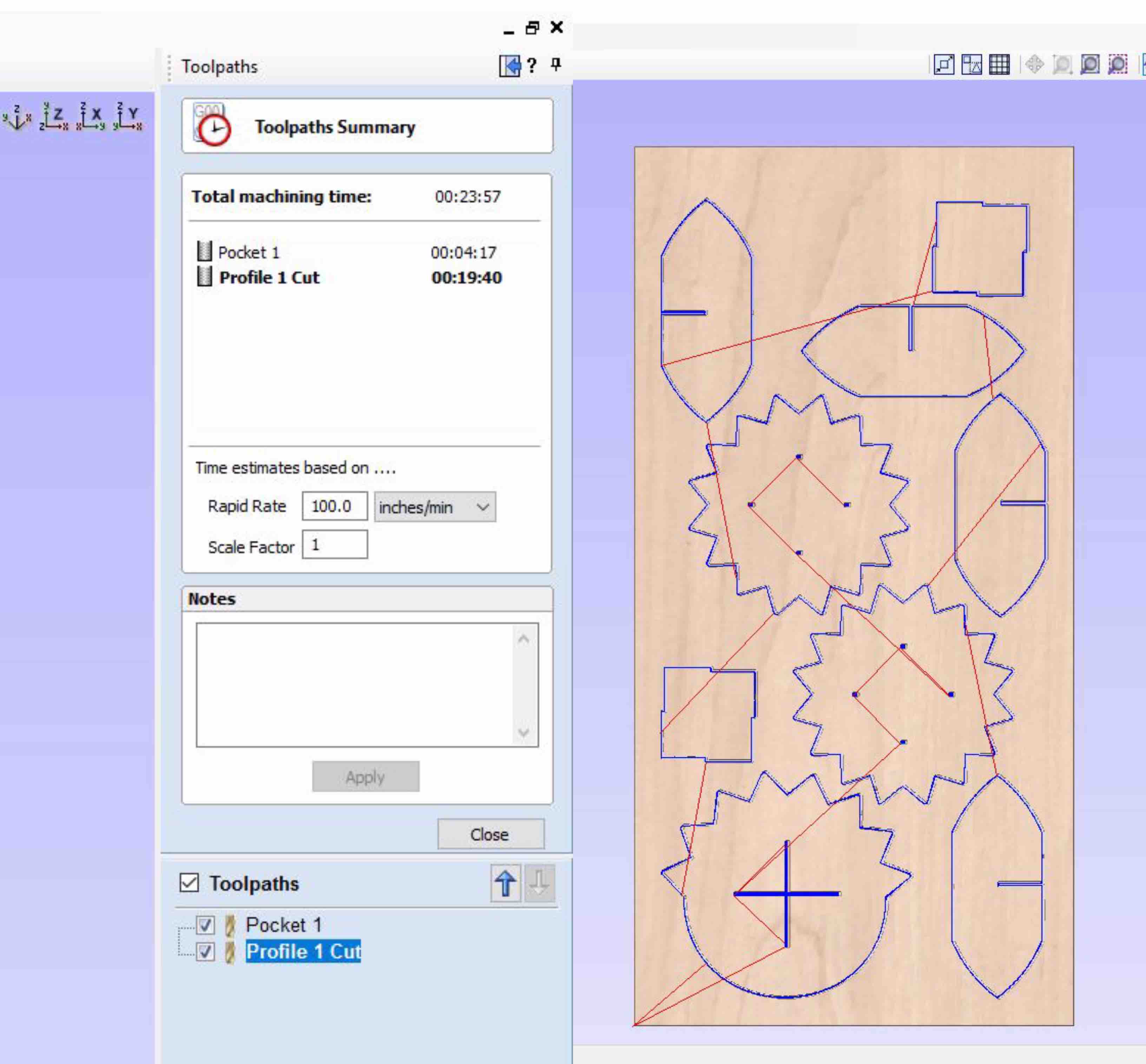
The final step is to test run each of the routing activities. These are previewed in the 3D View tab. If they appear to run smoothly the toolpaths are the saved to a flash drive with the shopbot file format.
Routing Process
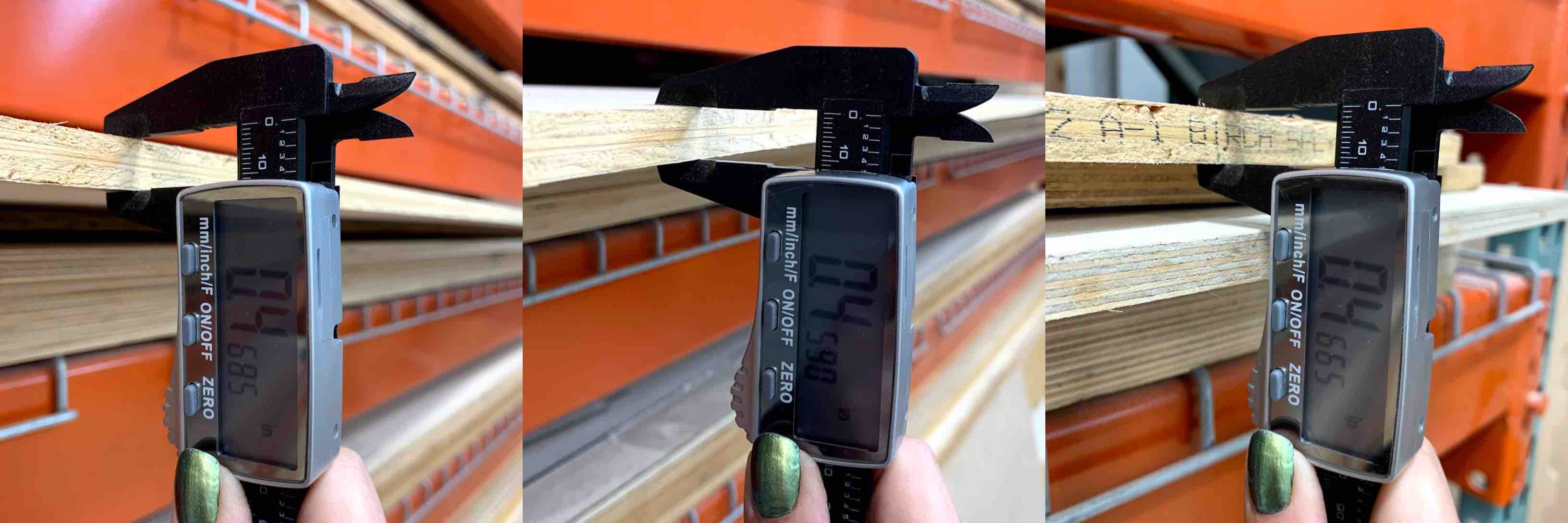
When working with the ShopBot CNC Router it is important to include all safety precautions. Be sure long hair is pulled back, closed toes shoes and the proper clothing is worn, ear and eye protection is used and material is measured correctly. Using an outside caliper i took the thickness measurement at both ends and in the middle of my board. This provided me with the average measurement of the material thickness. This helps to work towards the best end result. For this project I used .5” birch plywood.
This sheet was then loaded onto the CNC ShopBot. Taking the 4’ x 8’ birch plywood and edge is placed onto the CNC router. This sheet is then slid back on the table until the edge in hand lines up with the edge of the router table. Walk around the router and check the alignment at all four corners. This will straighten the piece.
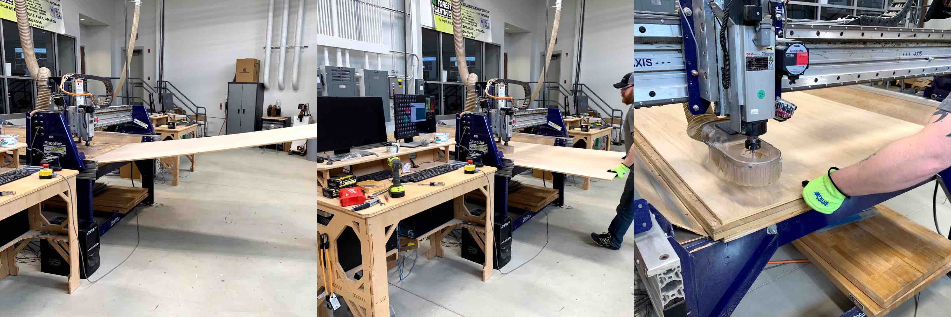
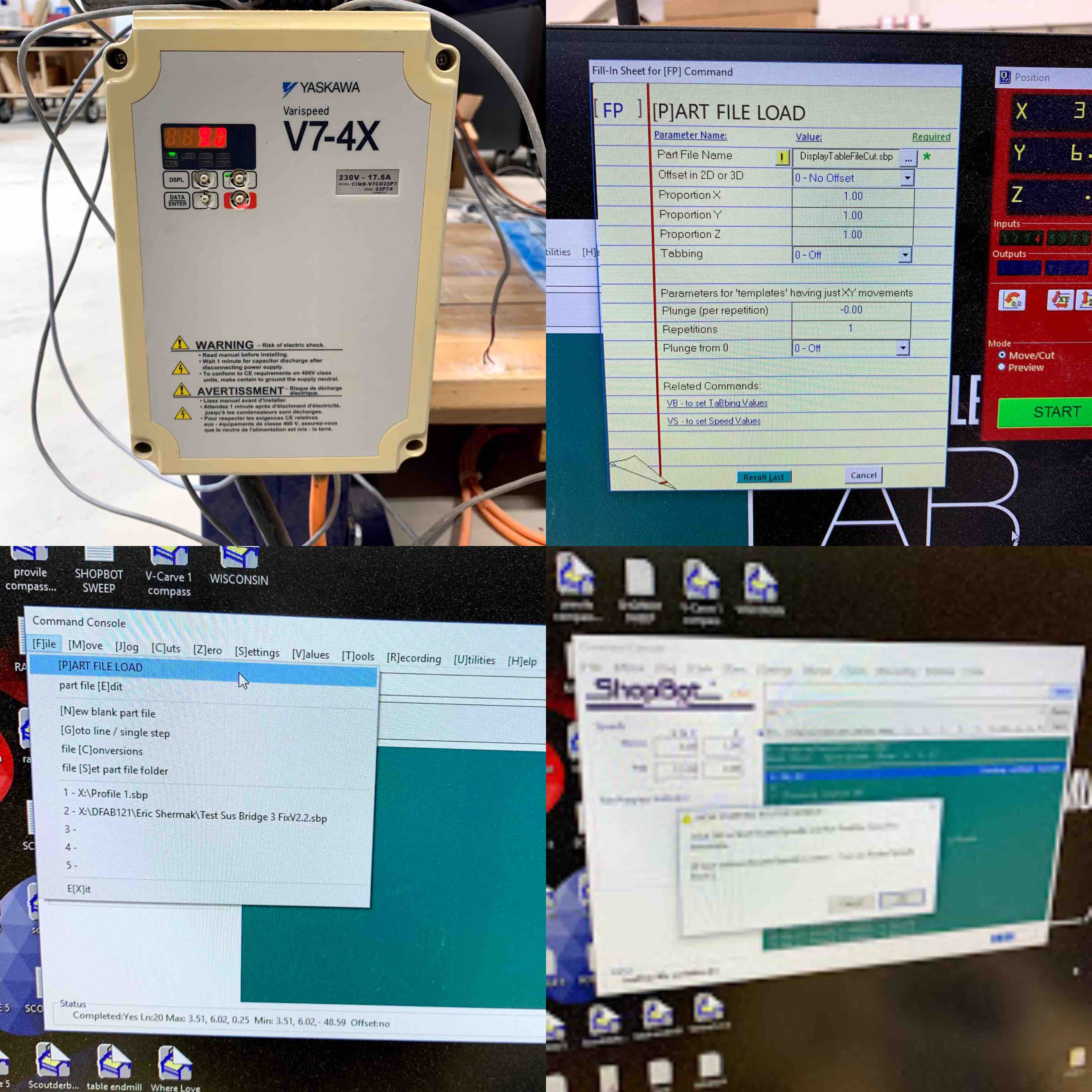
Using the cordless drill and the fastening screws, each corner should be tightened down in place. With our ShopBot we have a layer of sacrificial material. This is the material we fasten our sheet to and is made from MDF (medium density fiberboard). This also takes the brunt of the cut through from the ShopBot creating the necessary pieces. I then referred to the monitor run for the computer of the ShopBot. I opened the ShopBot software.
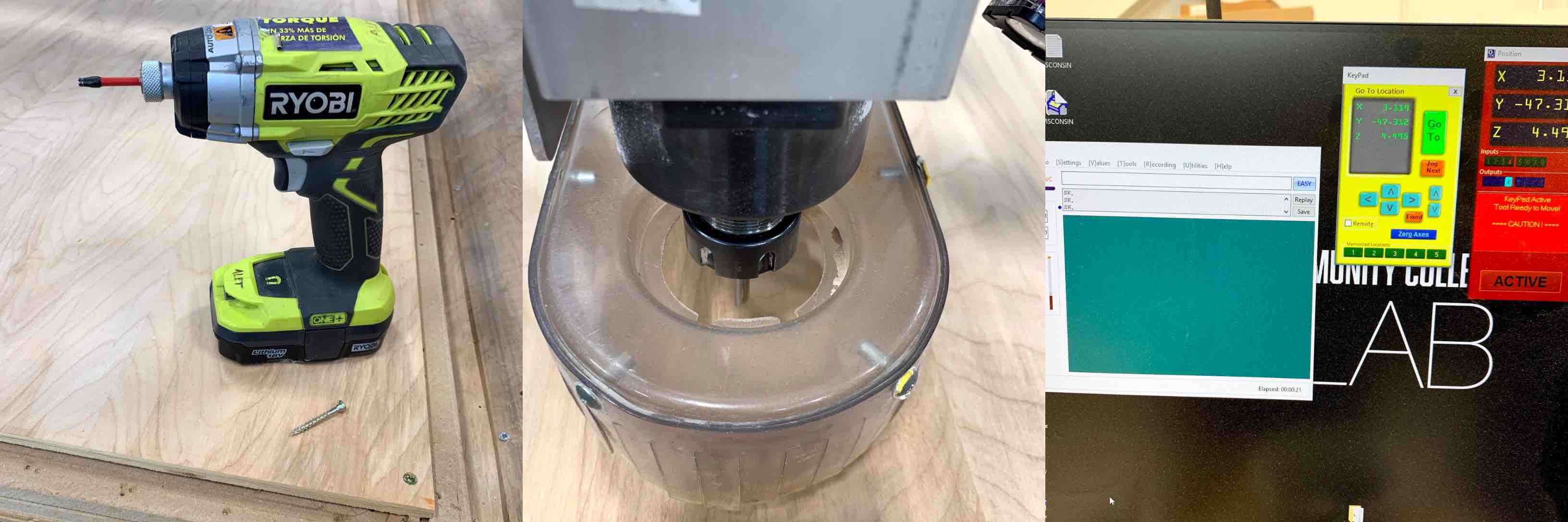
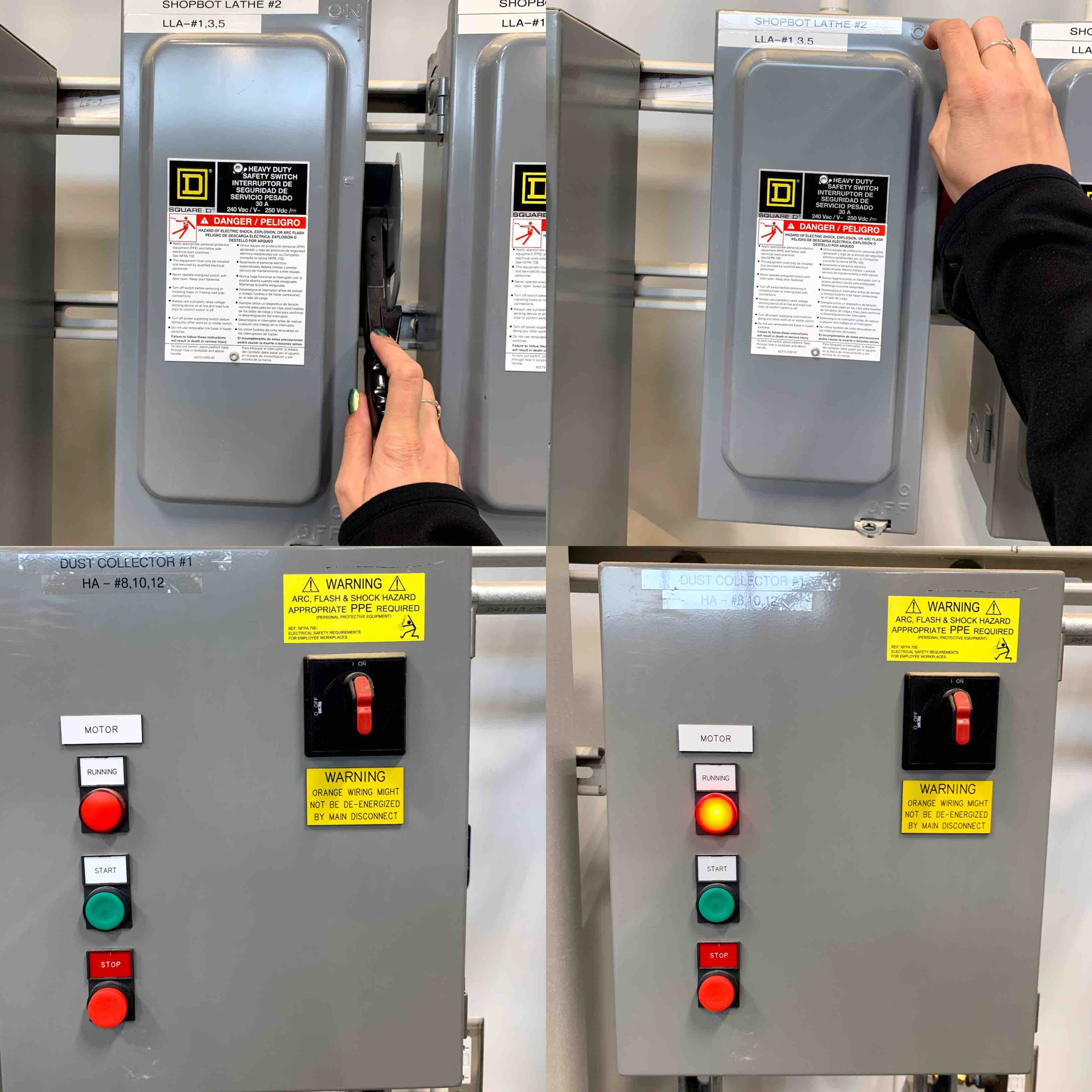
Once the material is fastened in place it was time to give the machine power. Moving to the location of the breaker I flipped it from the off position to the on position. This then began to power the CNC ShopBoth Lathe 1. With the power running to the machine the dust collector can be turned on as well. This will keep the excess material that is being removed sucked out of the way of the cut tool.
Within the software I am able to move the arm of the machine. The end mill equipped is then used to zero all of the axis’. I moved the arm all the way to the left and all the way down do that it was in the bottom left corner. I was able to use this as my zeroing point for the X & Y axis’.
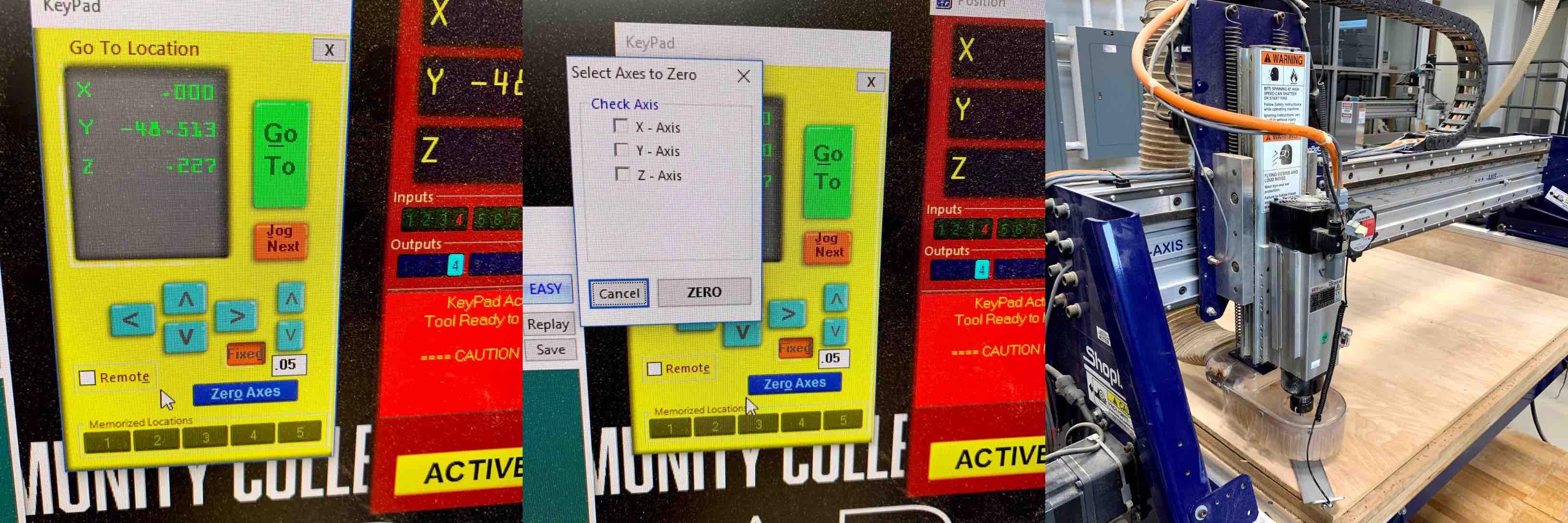
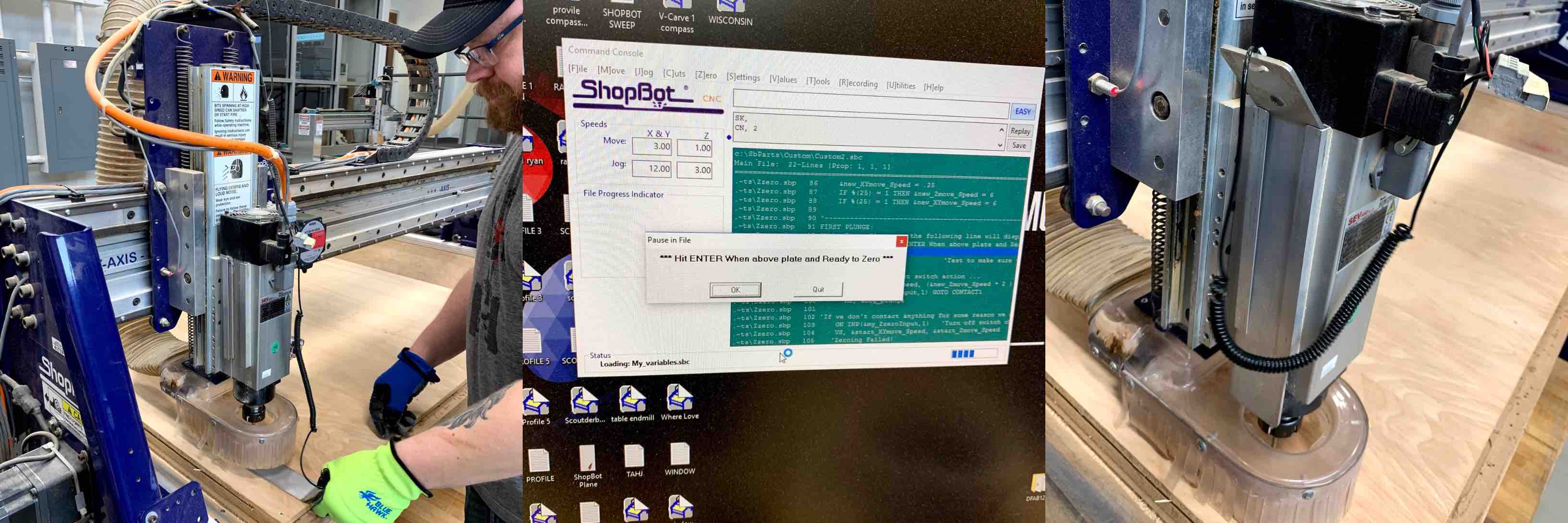
Using the zeroing plate stored on the left side of the arm the Z axis can be zeroed out. Having a zero point is important for the machine to function within the correct dimensions. Using the program option and with the zeroing plate in place under my end mill, I selected the machine to zero the Z axis. The program drops the end mill until it barely comes in contact with the zeroing plate. It then raises the arm and set the zero point.
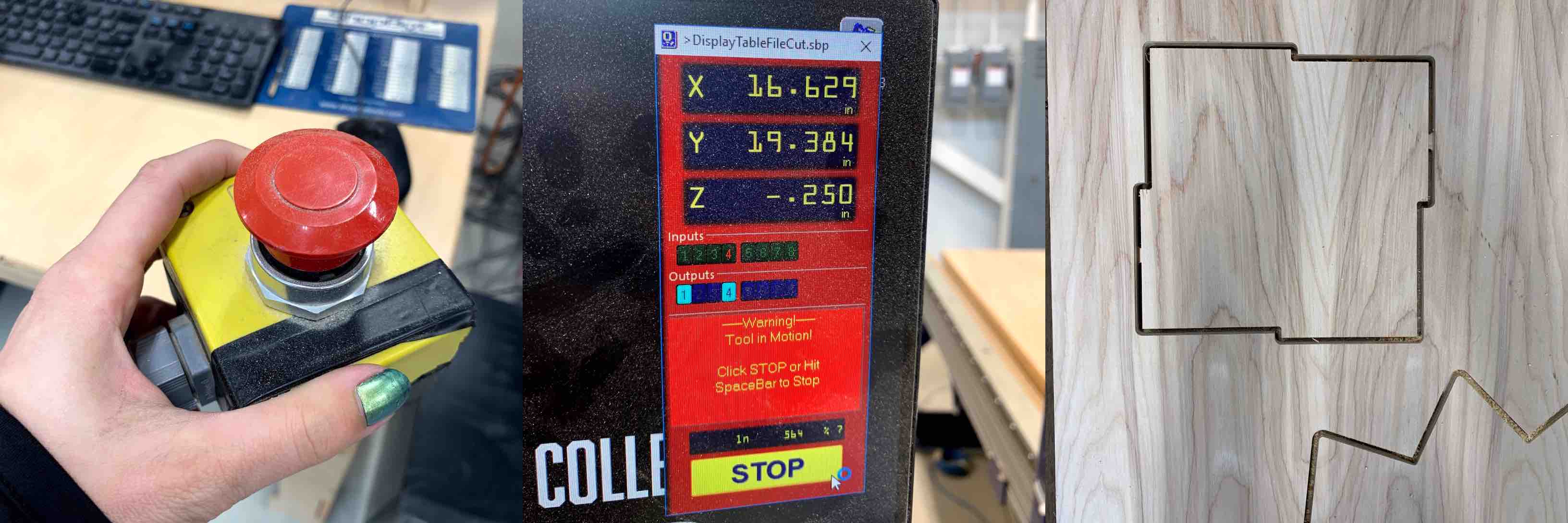
The last few steps include turning on the spindle and loading the cut file. The spindle was set to 9,000 RPM. This is based in the 2 flute .25” end mill that was loaded and used. Turning the V7-4X spindle control on began to feed the end mill with power. This caused it to spin and prepare to run the cuts. The cut file also needs to be loaded into the machine software for it to know what paths to follow. I loaded my part file and had it run.
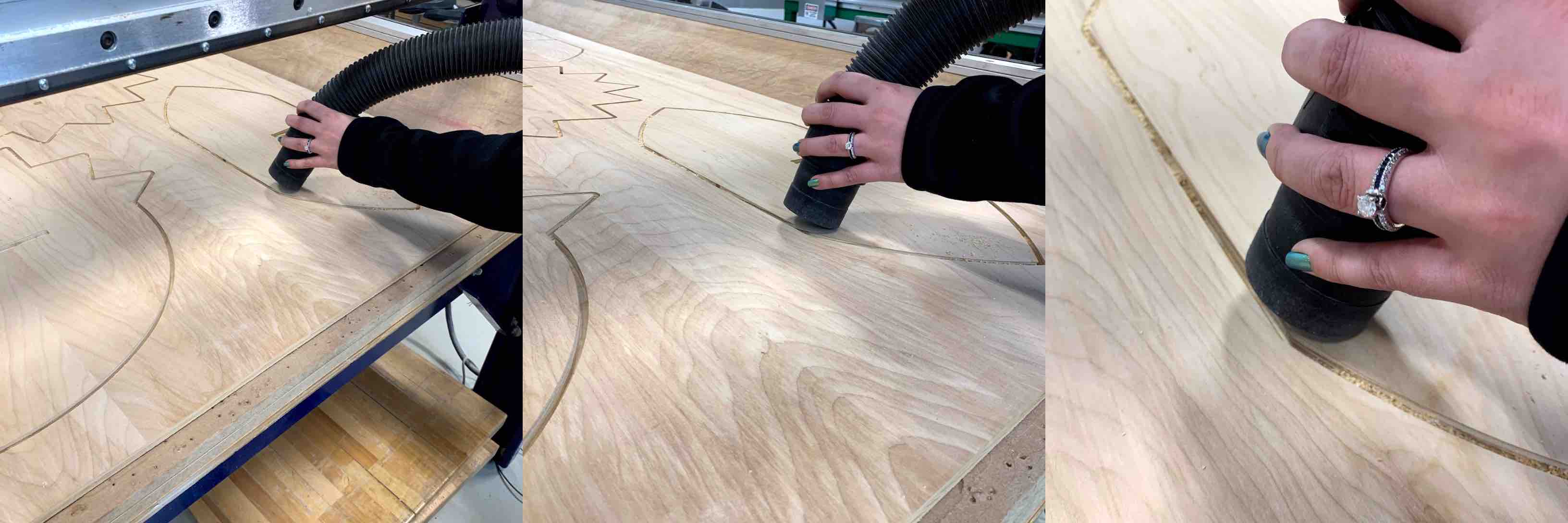
Being sure to keep the emergency stop button in hand as another safety precaution I let the machine run its tool paths. As the router worked it became clear where the tabs had been places. The connection could still be seen insuring no loose pieces flew from the machine.
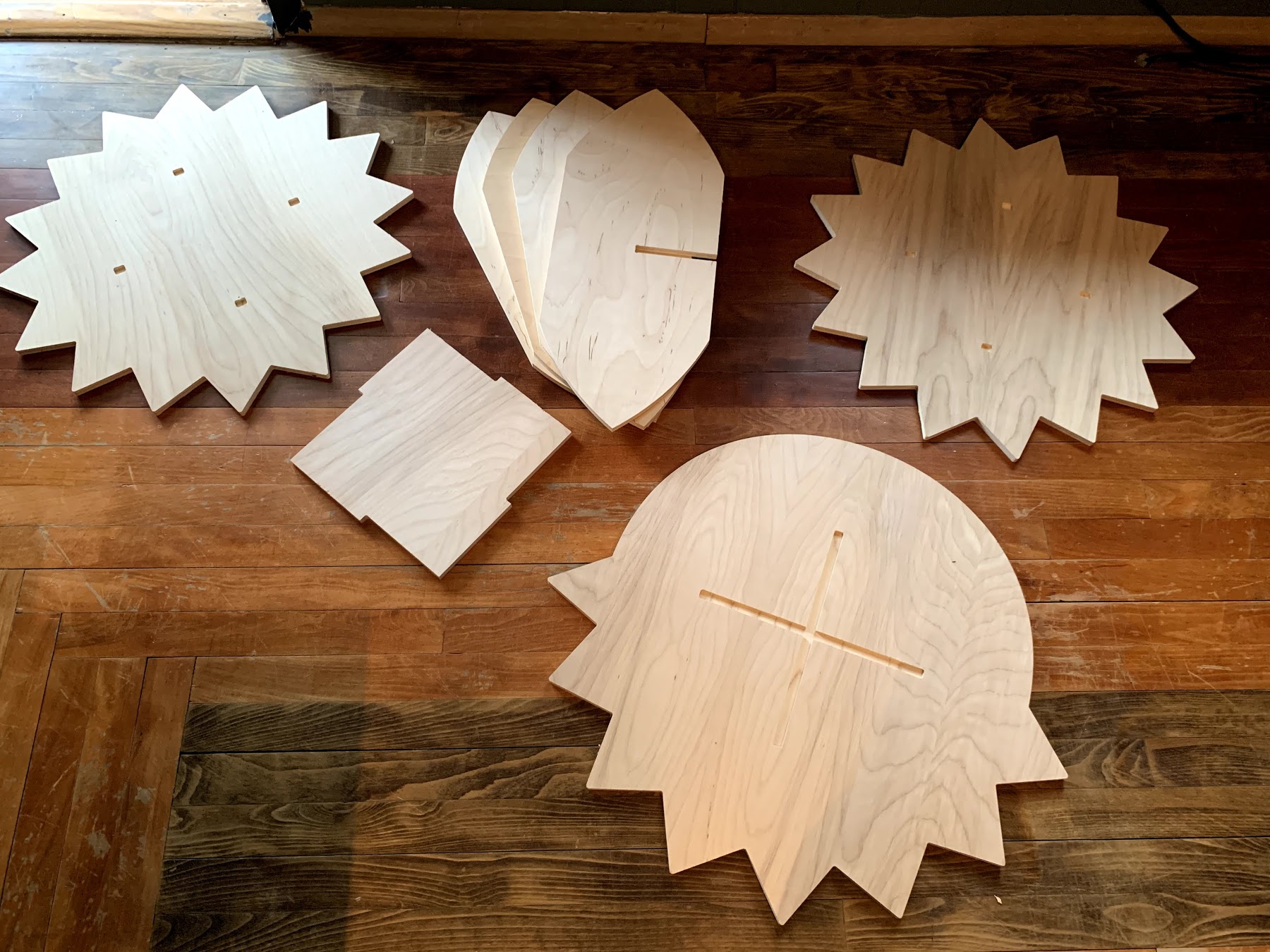
At the completion of the routing the machine will return its arm to the zero point. This can then be move to reveal the cut pieces. At this point it is important to ensure the spindle has been shut down, the dust collector can be shut down as well. This is a very important safety step to remember. Any impact with a spinning end mill can cause great injury. Before the tabs can be severed the remaining sawdust needs to be removed. Using a shotvac the sawdust is removed from all areas of the final run.
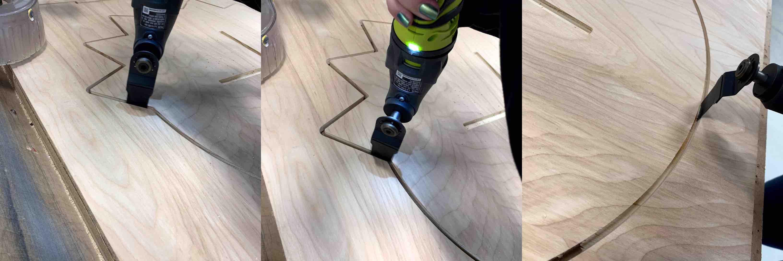
With the board cleared of excess sawdust and the arm moved you can now take the Roto Zip (an electronic hand saw) and remove the connection of the tabs. After this each piece can be removed from the 4’ X 8’ sheet. The screws can be removed from each corner of the left over scape. This is then removed in a similar fashion to how it was loaded.
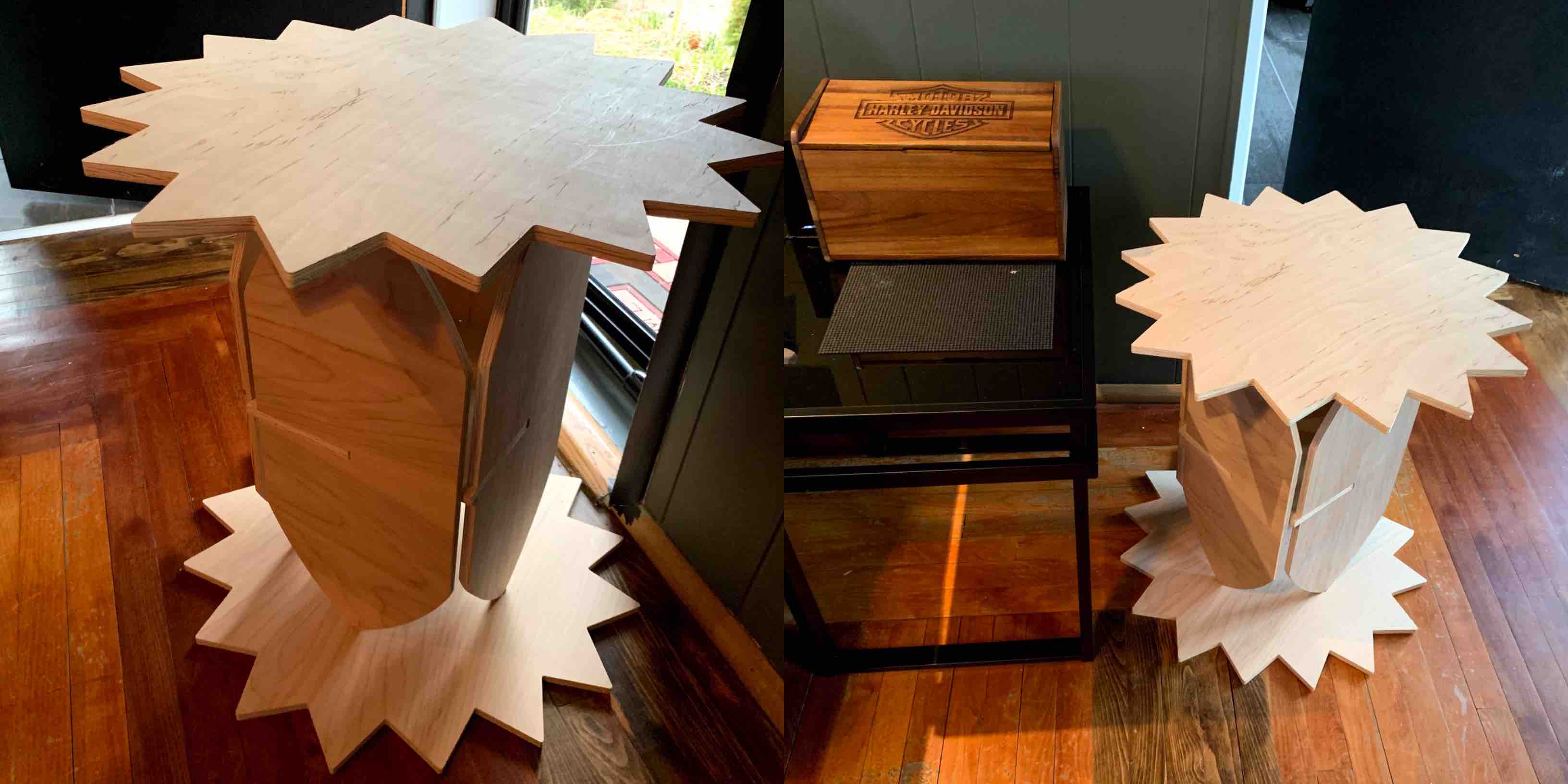
Make Something Big! … Constructed!
The construction of my something big is pretty simple. This is to ensure ease of use. It also come apart to store flat.
The first pieces that should go together is two of the leaf legs and the shelf. This starts with the stability of he structure. With these three pieces together the edges of the leafs should be places in the recess aligning with concept design.
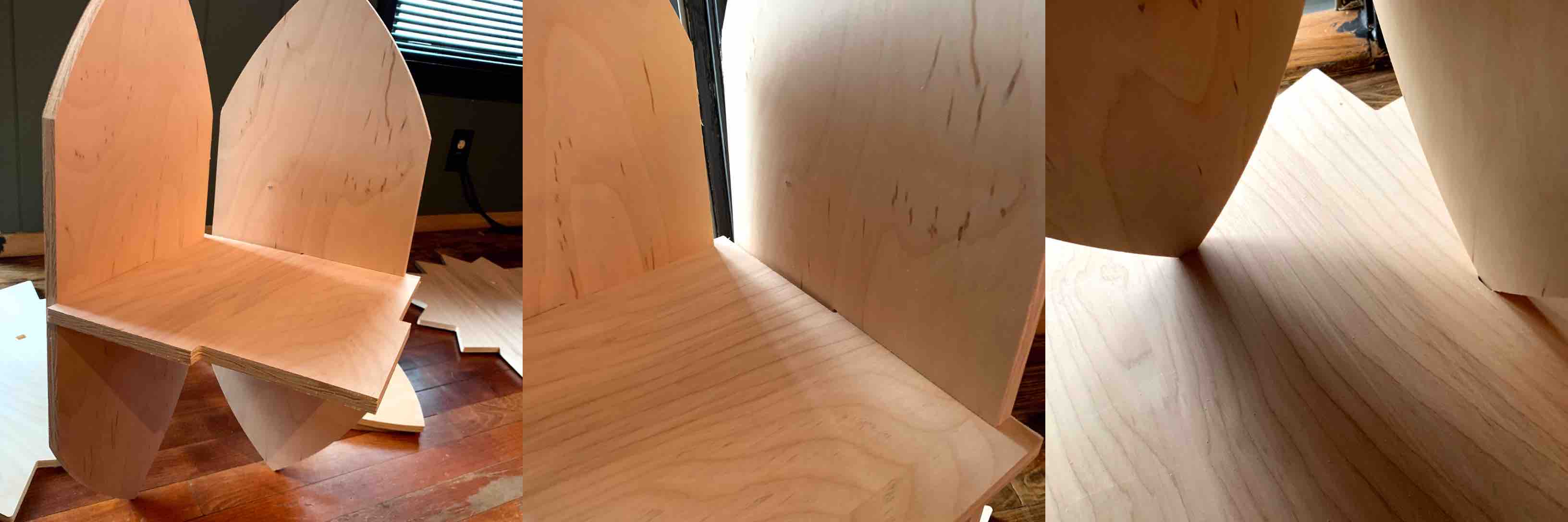
Each of the leaf legs should then be attached with the slotting and lined up in the recesses of the bottom piece.
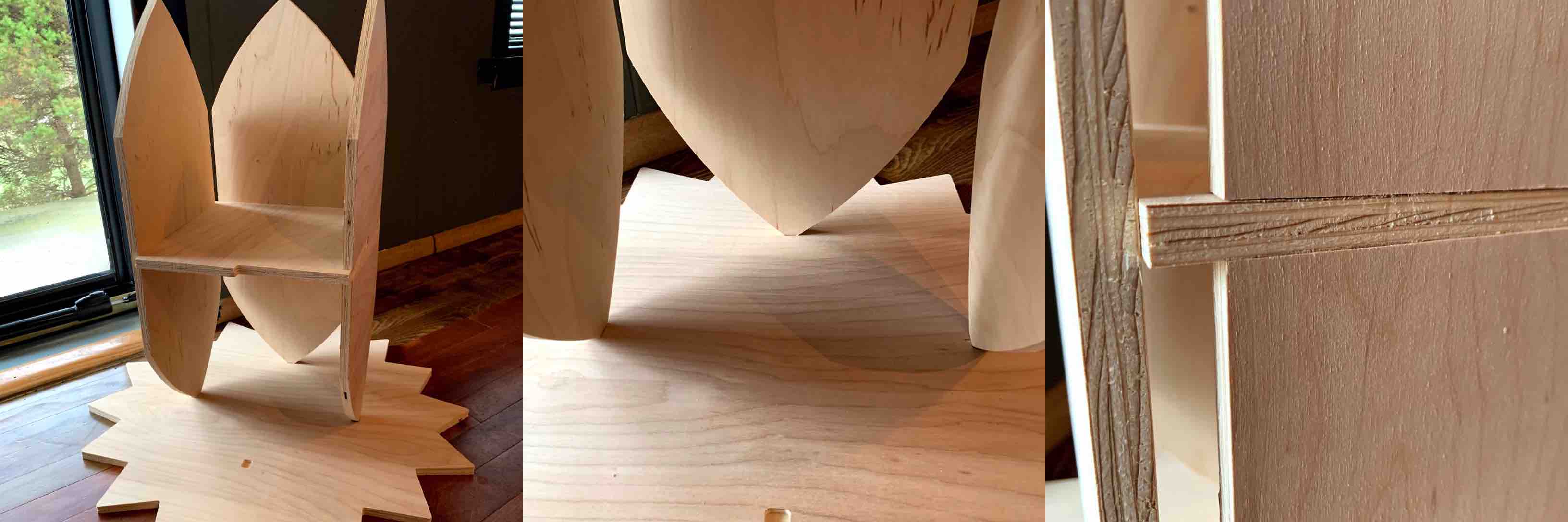
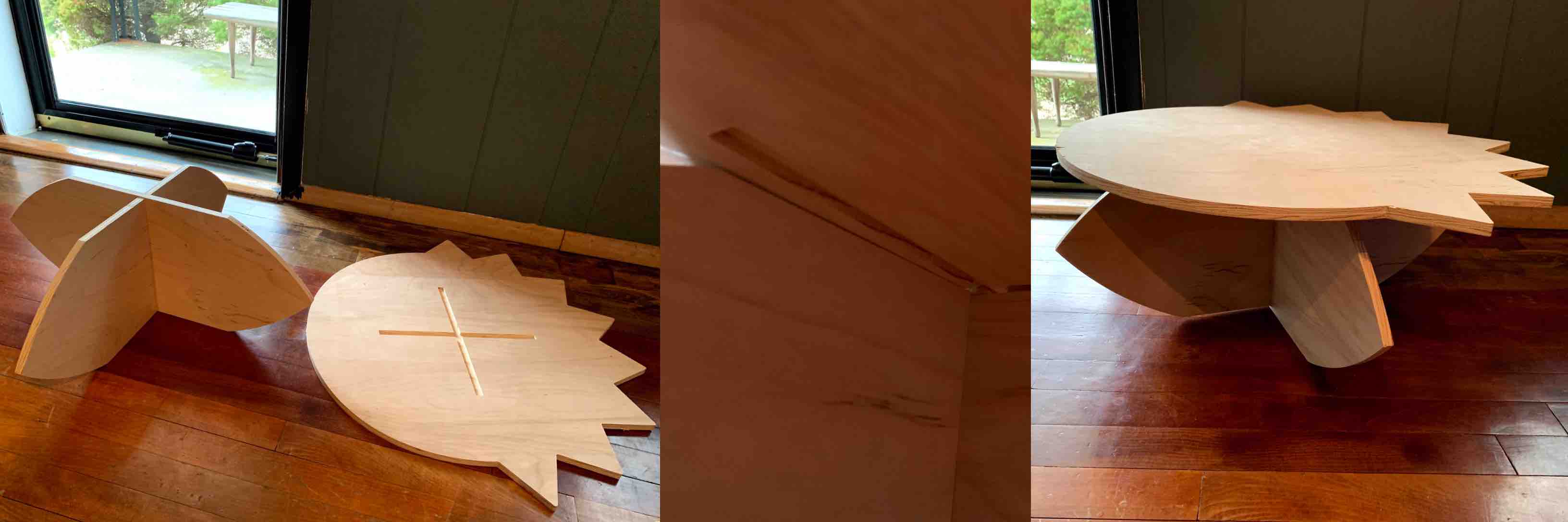
When all 6 of these pieces are together you will already feel retaining tension and it can at this point stand freely on its own. This is when the top piece should be added.
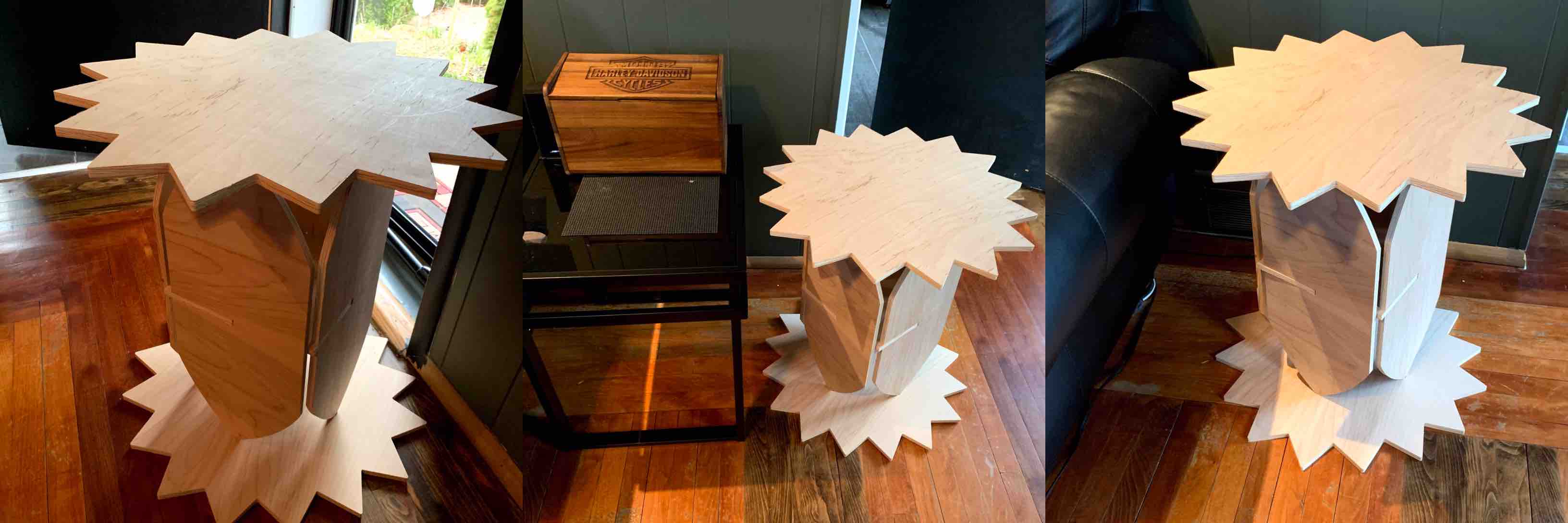
With the table top sun in place, being sure to align the top recesses as well, the tall construction of pieces is complete. This holds its structure, weight and places well next to a couch in place of an end table.
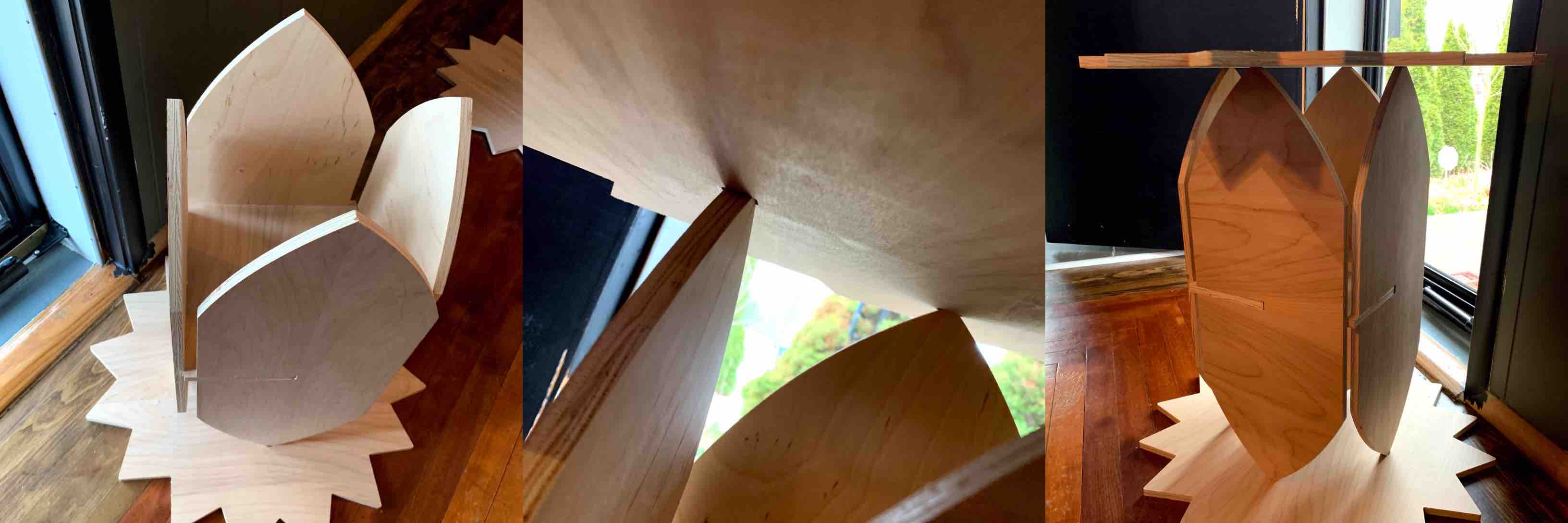
The tall table must be disassembled in order to assemble the smaller version. This was the original intention, that the table could be assembled in two different stable constructions. With two of the leaf legs and the sun/moon table top the smaller construction can be competed. Taking the leafs and using the slots previously supporting both structure and the middle table are used to intersect. This in turn creates a cross shape.
When referring to the underside of the table top there will be a recess in the same shape. This shape directly lines up with the leaf legs. When placed together the recess allows to legs to fit and create a more stable construction.
After construction the small table proved quite sturdy and durable. The table compared to half the height of the taller construction. This was the perfect height for the intended use as a child’s education work table.
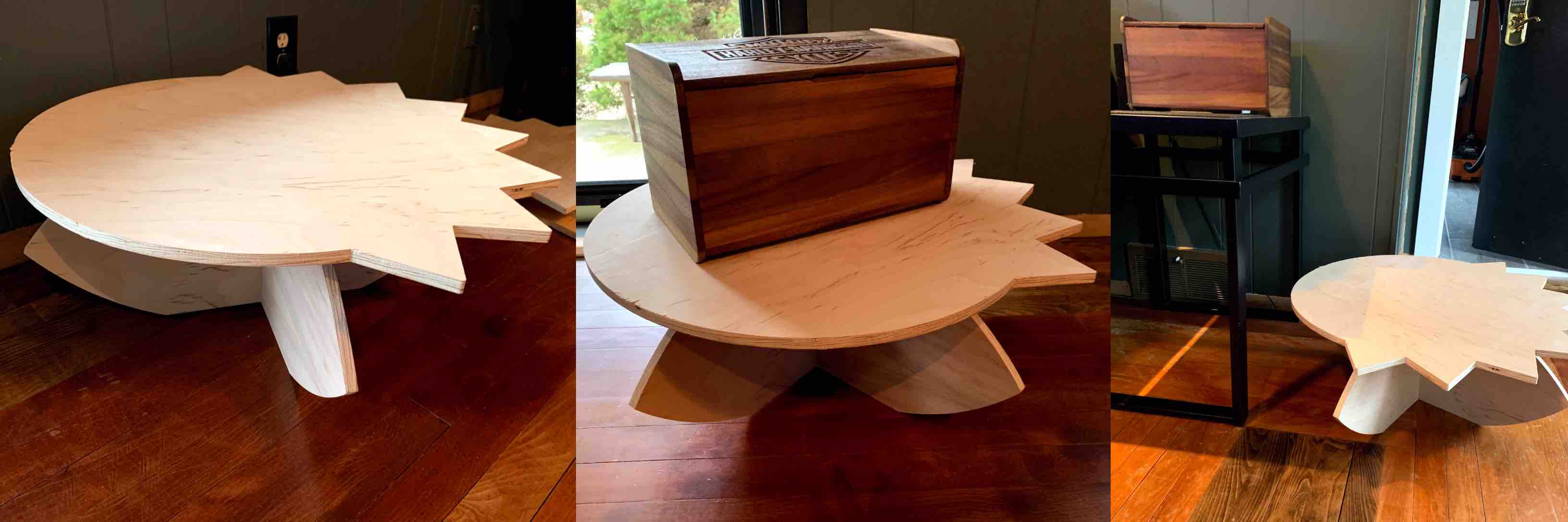
Hero Shots
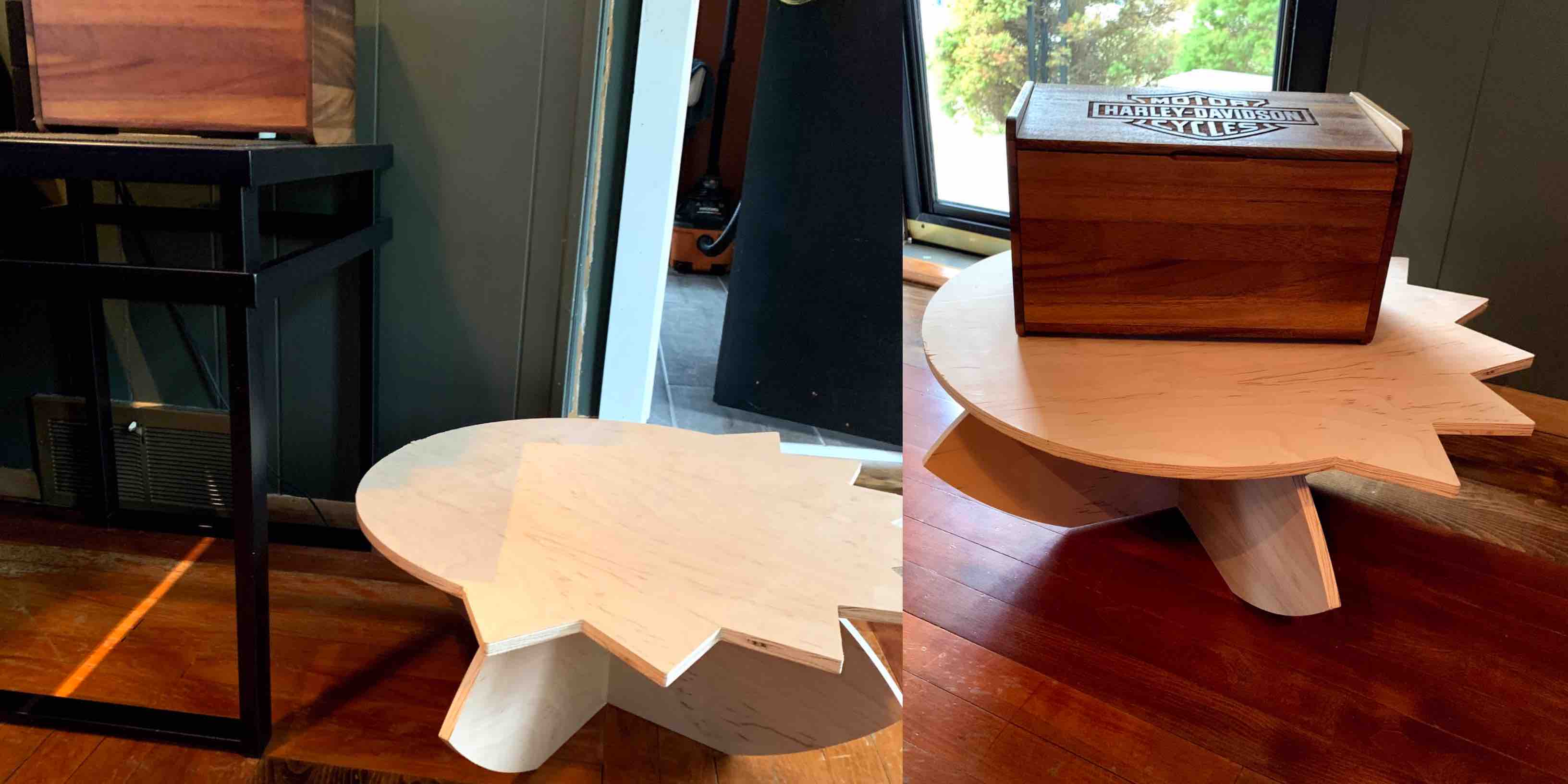
Scaled Comparison
Complications
Before moving on to my next shape, while modeling in Fusion 360, I wanted to adjust the sharp edges of my sun. This table being designed to be placed next to a couch, window or even in a child’s room. Therefore I wanted to make it safer than having sharp edged extruding from the shape. To do this I used the Fillet tool. I selected the edge line, I applied the fillet tool and rounded them each. - On a side note this was wasted work and time because the fillet did not transfer from program to program and had to be recreated in Aspire before using the CNC router.
When extruding the rays of my moon and sun table top I ran into a bit of a struggle. The extrusion raised the rays by the material thickness. This then made the circle a separate shape from the rays. This is not what I intended to happen. Stepping back and undoing this took me back to the stage where they were faces. I then extruded them again and found an option that allowed me to extrude in a negative distance. This lines all my pieces up and created my shape the correct way, as shown in the modeling stages above.
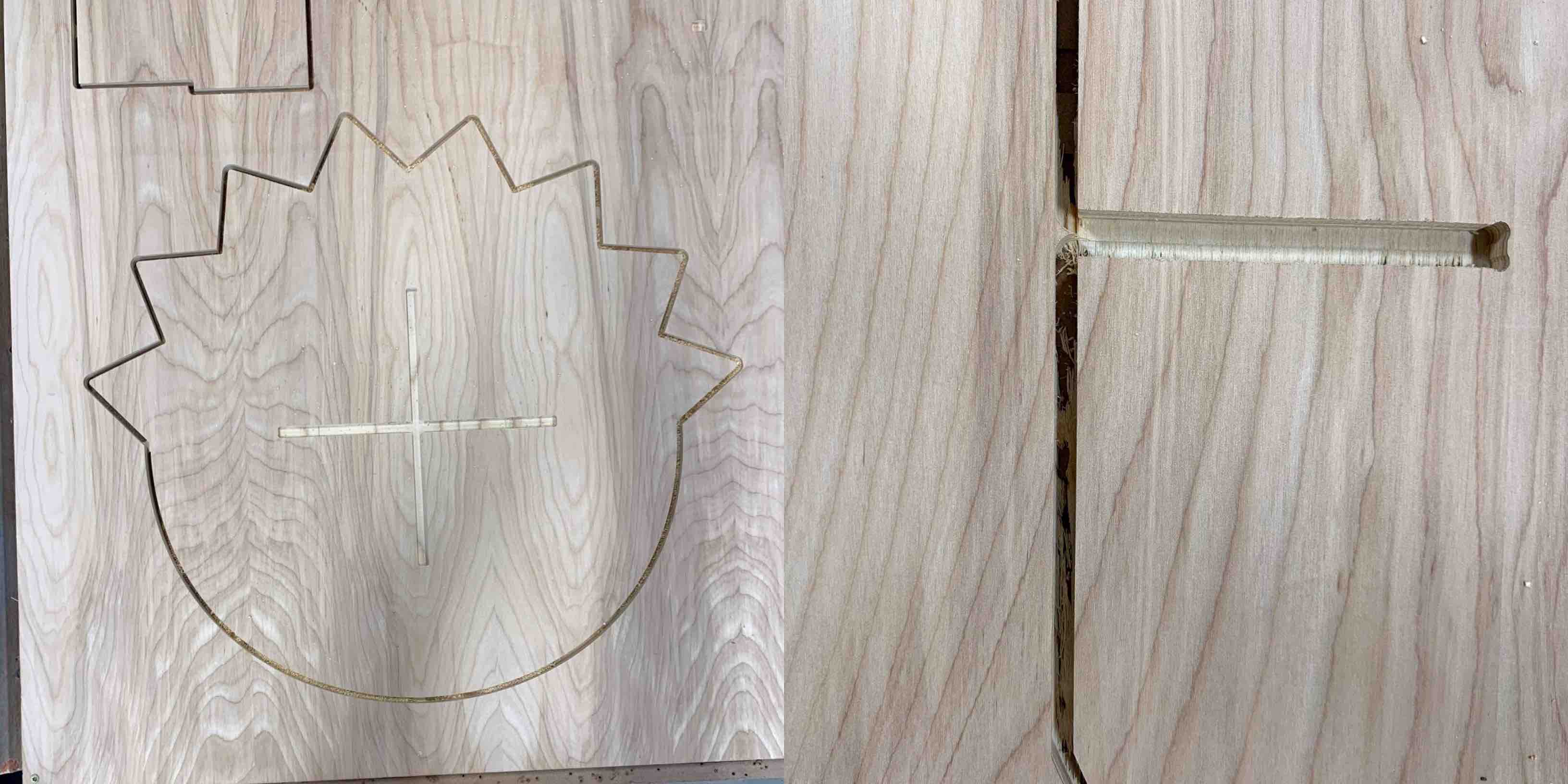
Another complication appeared after running my scaled down test cut on the Epilog Laser. The pieces came together quite well for the taller standing table design. However, I did end up having enough room on my end plywood sheet to cut another replication of the top to be added on the bottom for stability. The bigged complication revealed itself in the shorter table design. With the leaf legs being rounded the pieces swayed from side to side when intersected and there was no stability in the table when pressure was applied in different areas. I had to remove a section from the side to create flat edges to my leaf legs. This improved the stability immensely and it was stable.
THe last big complication I faced was based on the material depth setting. There was a slight depth change that was not accounted for. It needed to be adjusted from .51” to .53”. Due to the inability to cut through the first time there was a visible wooden connection left behind. Due to this the pieces could not be removed. I had to return to Aspire, complete the material depth of cut, reloaded my file into the machine and run it one last time to release each piece. This had an easy solution once the issue was determined.