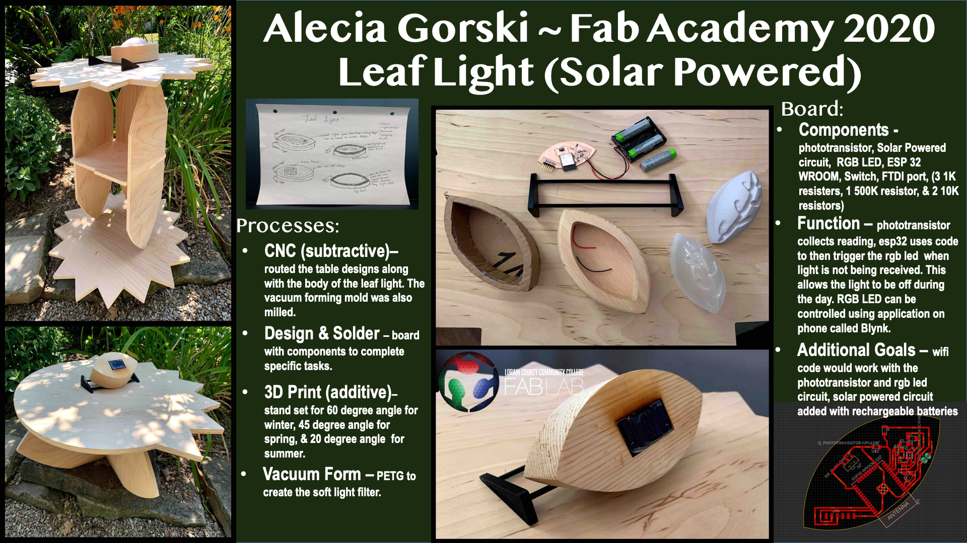
Leaf Light - by Alecia Gorski
Goal
My goal in Fab Academy was to better understand the technology surrounding us. I wanted to design a project I knew nothing about and learn each step. The Solar Powered Leaf Light became my idea.
What does it do?
It lights up! In all its not so much simplicity, what it does is it lights up. My solar panel leaf light collects clean energy and runs off its own program. It connects to the user and can be personalized by color. It reacts to the light available and provides education to all who are curious.
Who has done what first?
- DIY Solar Powered Night Light at Home
- DIY Auto turn off/on solar street light
- How to Make Solar Panels Yourself with Epoxy Glue
- Solderless Solar Night Lamp Video Tutorial
- Automatic Solar Rechargeable Light Circuit
- How to make an automatic night light @ home with solar panel
My overall concept of building a light powered by solar energy is not a new one. However, my intentions for the overall project introduce concepts that are original to me.
What I Designed and With Which Processes
I designed the shape and look of the leaf light. I routed the leaf shape that I 3D modeled. I vacuum formed the soft light filter over the REN board model that I routed on the ShopBot CNC router. I designed the circuit board in Eagle CAD and cut it on the LPKF. I soldered all the components and programmed it with the program I created. I designed the display table in Fusion 360 and parametrically laid out the pieces to be sure all pieces were compatible. I then used the ShopBot to CNC all pieces. I 3D modeled and 3D printed the the stand for the light to be sure that the solar panel was receiving optimal light to charge.
Materials
| Materials Used | Cost | Total | Where they came from |
|---|---|---|---|
| Wood Pieces for Body | Upcycled - $0 | 0.00 | Upcycled from nearby businesses |
| PETG | Upcycled - $0 | 0.00 | FabLab Supply |
| ESP32 | Fab Inventory - $3.80 | 3.80 | FabLab Supply |
| 1 K resistors | Fab Inventory - $0.01 | 0.03 | FabLab Supply |
| 500 OHM resistors | Fab Inventory - $0.01 | 0.01 | FabLab Supply |
| 10 K resistors | Fab Inventory - $0.01 | 0.02 | FabLab Supply |
| Switch | Fab Inventory - $0.57 | 0.57 | FabLab Supply |
| FTDI Pins | Fab Inventory - $0.67 | 0.67 | FabLab Supply |
| RGB LED | Fab Inventory - $0.53 | 0.53 | FabLab Supply |
| Photo Transistor | Fab Inventory - $0.15 | 0.15 | FabLab Supply |
| Battery Pack | Outsource - $2.12 | 2.12 | Amazon |
| Solar Panel | Outsource - $1.00 | 1.00 | Amazon |
| 4’ x 8’ Plywood | Outsource - $24.85 | 24.85 | Home Depot |
| Total | Cost/per | $32.95 |
What Parts and Systems Were Made
- Leaf Light Body
- Soft Light Filter
- Circuit Board
- Display/Educational Table
- Charging Stand
- Program to interact with available light
My Code
This code is written by Alecia Gorski
// Written by Alecia Gorski

//uses a phototransistor reading and transmits to the esp32, this then turns the led on or off
//based on the readings received from the phototransistor

//Fab Academy 2020 (July)


int photoTran = 27;
int reading = 0;
int LEDpin3V3 = 2;
int LEDpinR = 26;
int LEDpinG = 25;
int LEDpinB = 32;

void setup(){
pinMode(photoTran,INPUT);
Serial.begin(9600);
pinMode(2, OUTPUT); //sets the digital pin 2 as output
pinMode(26, OUTPUT); //sets the digital pin 26 as output
pinMode(25, OUTPUT); //sets the digital pin 25 as output
pinMode(32, OUTPUT); //sets the digital pin 32 as output
}

void loop() {
reading = analogRead(photoTran);
Serial.println(reading);
delay(100);

if (reading > 3800) {
  digitalWrite(LEDpin3V3, LOW);
  digitalWrite(LEDpinR, LOW);
  digitalWrite(LEDpinG, LOW);
  digitalWrite(LEDpinB, LOW);
  //LED should be off during the day
}

else if (reading < 3800) {
  digitalWrite(LEDpin3V3, HIGH);
  digitalWrite(LEDpinR, HIGH);
  digitalWrite(LEDpinG, HIGH);
  digitalWrite(LEDpinB, HIGH);
  //LED should be on during the night
}
 }
Explained
The way that I designed the code was to control each pin. I have each pin set to a specific function. R, G and B each have their own pin(with PWM), as well as the power pin for the RGB LED. The phototransistor is set to its own pin as well. Each of these pins are assigned their own functions that interact with the microcontroller.
int function assigns each of the pins so that my code knows how to link each pin to the correct component. “int” stands for integer and is a data type. This data type describes a range of values that are available to be used within that specific variable. As long as the integer fits within that range it can be used. For example, int LEDpinB = 32 means that the variable is an integer being called LEDpinB and its corresponding value is 32. This value then carried over to pinMode(). pinMode() allows the code to work with the assigned pin and set it to OUTPUT. This OUPUT setting tells the code that the pins are the reaction in the process.
Within the void loop() section of my code there is an if…else statement. This statement is how my phototransistor is interpreted. IF the reading, aka the amount of light coming into the path of the phototransistor, is responding below the threshold of 3800 the light is LOW of off. ELSE the phototransistor reading is above the threshold and the assigned LED pins are set to HIGH or On. The readings can be seen on the serial monitor.
These settings are how my light turns on at night and turns off during the day to conserve energy.
This code may seem simple and resemble other easy to find codes online, however I have little to no experience writing code. One of the many reason I wanted to enroll in this class was to expand my education in this area. Learning each of the required pieces to build a functional code is the first step. By writing this code I found that there are certain languages and wording that must be used to communicate with the microcontroller. By speaking the microcontroller language you can communicate with the components and make this seemingly simple reaction happen. The more I can build into the code the better. With the foundation of code building now proven to work with my own board design I plan to continue to develop my skills in this area and expand the code to be more complex beyond this course.
Credit to - Code
This code belongs to Arduino Blynk. This connects with the esp32 and can be programmed to control the RGB LED.
/*************************************************************
  Download latest Blynk library here:
    https://github.com/blynkkk/blynk-library/releases/latest

  Blynk is a platform with iOS and Android apps to control
  Arduino, Raspberry Pi and the likes over the Internet.
  You can easily build graphic interfaces for all your
  projects by simply dragging and dropping widgets.

    Downloads, docs, tutorials: http://www.blynk.cc
    Sketch generator:           http://examples.blynk.cc
    Blynk community:            http://community.blynk.cc
    Follow us:                  http://www.fb.com/blynkapp
                                http://twitter.com/blynk_app

  Blynk library is licensed under MIT license
  This example code is in public domain.

 *************************************************************
  This example runs directly on ESP32 chip.

  Note: This requires ESP32 support package:
    https://github.com/espressif/arduino-esp32

  Please be sure to select the right ESP32 module
  in the Tools -> Board menu!

  Change WiFi ssid, pass, and Blynk auth token to run :)
  Feel free to apply it to any other example. It's simple!
 *************************************************************/

/* Comment this out to disable prints and save space */
#define BLYNK_PRINT Serial


#include <WiFi.h>
#include <WiFiClient.h>
#include <BlynkSimpleEsp32.h>

// You should get Auth Token in the Blynk App.
// Go to the Project Settings (nut icon).
char auth[] = "Authentication Token";

// Your WiFi credentials.
// Set password to "" for open networks.
char ssid[] = "WiFi Name";
char pass[] = "WiFi Password";

void setup()
{
  // Debug console
  Serial.begin(9600);

  Blynk.begin(auth, ssid, pass);
}

void loop()
{
  Blynk.run();
}
The Blynk code is used in this project to expand the education of coding. My project isn’t just about having a functioning self-sufficient light, but to encourage learning in science and technology. The user can learn how to connect to the ESP32 with Blynk and be introduced to the idea of coding and application interaction by changing the color of the light. When the Blynk interface is no longer being used the user can re-upload the phototransistor code using Arduino IDE and the project is back to a self-sufficient light.
It worked! and It didn’t....Yet!
IT didn’t work just yet. A few aspects of my project did not quite pan out. The code has a few kinks I would really like to learn more about and fine tune. I would really like to work more with analogRead() and analogWrite() to control the RGB LED outside of the app. The solar circuit has been tested but still needs to be proved efficiently functional.
IT WORKED! The board worked. The ESP32 worked. The program I wrote worked. I have learned so much in this class and overall my project worked. I was able to form an idea in my mind, sketch it, model it in a 3D environment, build this concept and wire it to functionality. Coming from having little to no experience building and coding circuitry I am blown away by the possibilities. My whole concept came together and I am so proud of the project it became.
Evaluation
Evaluation Mentioned in Applications and Implications week 10
- This project should be evaluated on functionality and creativity. There are many different parts going into this project. The versatile display table, the light itself, and the application that communicated with it. This is more than originally intended and the hope is that the project comes together and works properly.
Current Evaluation Review
- In the end I stated that it should be evaluated on functionality and creativity. It is successful in its basic function of the LED reacting the the phototransistor. Creativity wise I think that my final project only became more creative along the way. Not only did I work to improve the overall outside look, but every step of the way I tried to add some creativity to the process. I believe the project came together and works well!
Questions
Determined in Applications and Implications Week 10
Questions I have:
- How do I design an application to communicate with my light?
- ANSWER: I used Arduino IDE to design and upload code that communicated with the microcontroller to control the led with the phototransistor. I also communicated with the ESP32 by using the Blynk app to change the colors. Being able to communicate with my board to control the light allows the project to be connected to the user. Not only was the project functional and educational but it is interactive!
- How can I bring my top and bottom light pieces together after construction of each? Should I use a glue or screws?
- ANSWER: I redesigned my project. I wanted to remove as many parts as possible to refine the look and the functionality of the light. After my 3D model was created I began to notice that it seemed quite large and too heavy. I realized that by minimizing the size by half and removing the need for connective hardware the end project was not only lighter and more compact by more appealing as well. This led me to the idea of creating the one piece lid that slides into the body fitting. This protects the circuitry and added depth. It is easily removable to add access to the board for educational programming.
Questions the project will answer:
- Does the light emit?
- ANSWER: Yes!
- Does the light turn on and off?
- ANSWER:Yes! and in reaction to the phototransistor readings!
- Does the application communicate with the light?
- ANSWER: Yes! Blynk communicates and changes colors.
- Does the display table hold the light?
- ANSWER: Yes! and much more.
- Does the light charge and continue to work?
- ANSWER: The solar applicaiton was my last challenge. It is currently still being tested.
Implication
My project developed quite a bit from when my idea was forming. I began to see it leaning more into education and functionality. The light can be self-sufficient and left in one place to simply complete its core function, emit light at night and turn itself off during the day. However the more I learned the more I wanted to open my project up to be a teaching moment. I don’t think enough kids are exposed to this type of education and I saw it becoming a piece that can be plugged into a computer and coded by the user. Now, with access to the board a user can follow the steps to switch between the phototransistor code and the Blynk Code. This would widen the range of use and learning the user can obtain. They now will be working with designing and using an application, as well as wireless connection protocols.
I am proud of how my project developed and I now see the implications being to grow this project into an educational tool and not just simply a light. I still do not have plans at the moment to create and sell this commercially, however, I would like to continue to work with the project I made to widen the range of education that reaches not only the youth I teach but anyone who may be interested in this kind of fabrication work.
Final Presentation Slide
Final Presentation Video
Useful links
- Principles, Practices, and Project Management
- Computer Aided Design
- Computer Controlled Machining
- Input Devices
- Applications and Implications
- Output Devices
- Interface and Application Programming
- WildCard Week
- Final Project Development and Process
Files
License
Leaf Light - Solar Powered by Alecia Gorski is licensed under CC BY-NC-SA 4.0