9. Input Devices
This week I worked on input devices and the programming required to obtain the desired response.
Useful links
I contributed the analog input readings and explanation of how it is interpreted to the group site.
Research
With the self made board created in week 6 there is an ATTiny1614 with 2 push buttons and 2 LEDs. These additional components should be able to be programmed with the microcontroller to react. This could mean a blink, a fade or any reaction you code it to complete.
The Arduino is tested first to better understand the software and how it communicates with the Arduino board. The Arduino board is then replaced with the connection to the programmer and the self made board. The software is then used to communicate with the new connections and complete an input.
Arduino Test
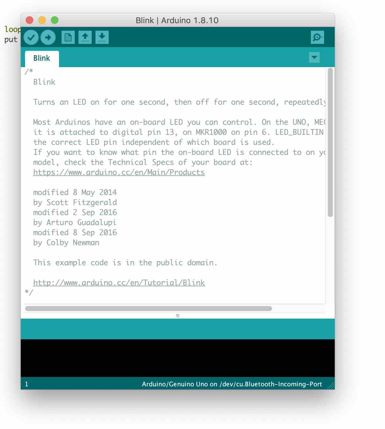
I used the Arduino board and software to input a command so that the LED in the board would blink.
I then set up my Arduino to Computer connection. The Arduino had a cable that connects to a USB port on one end and the Arduino board at the other.
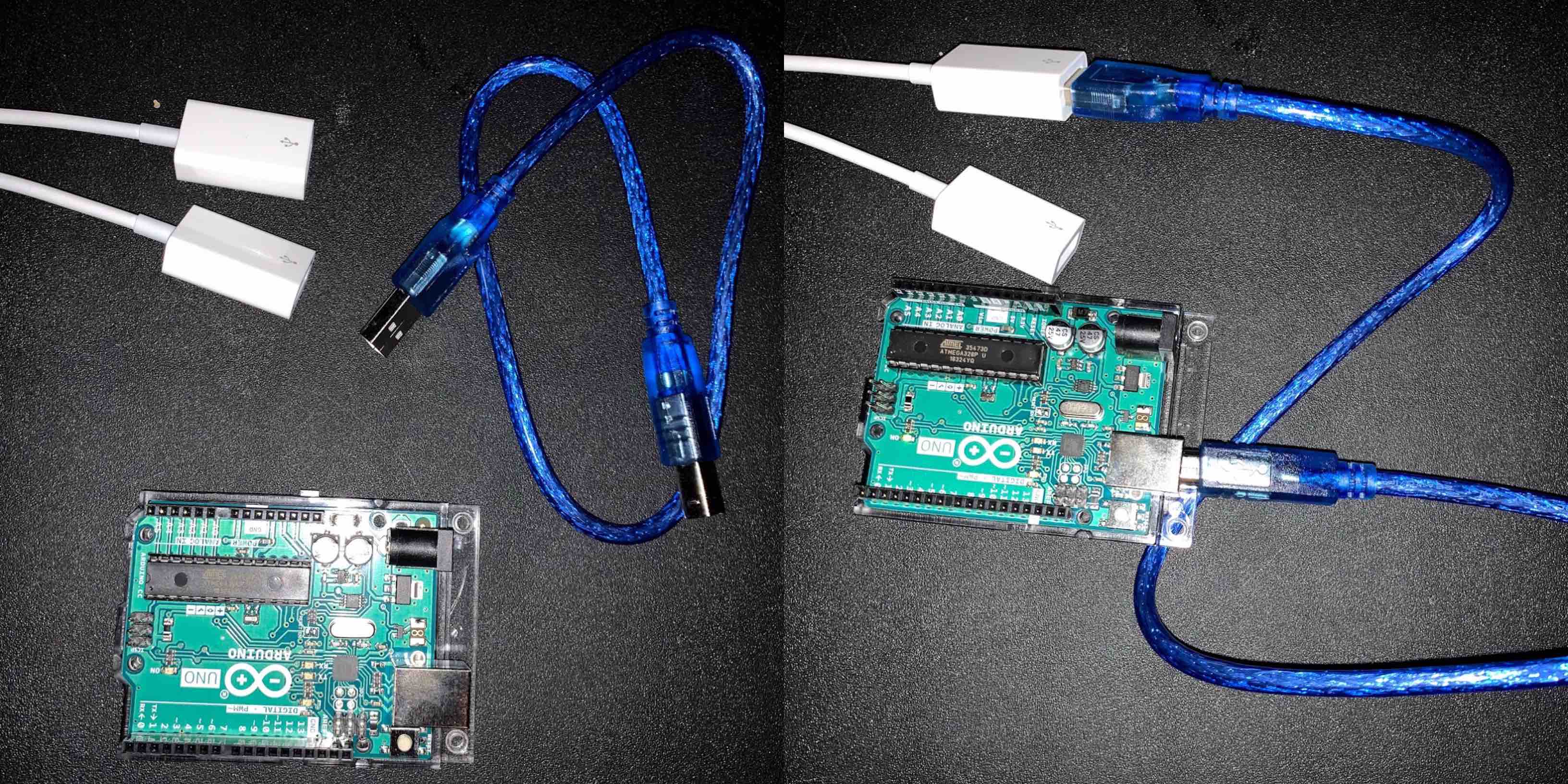
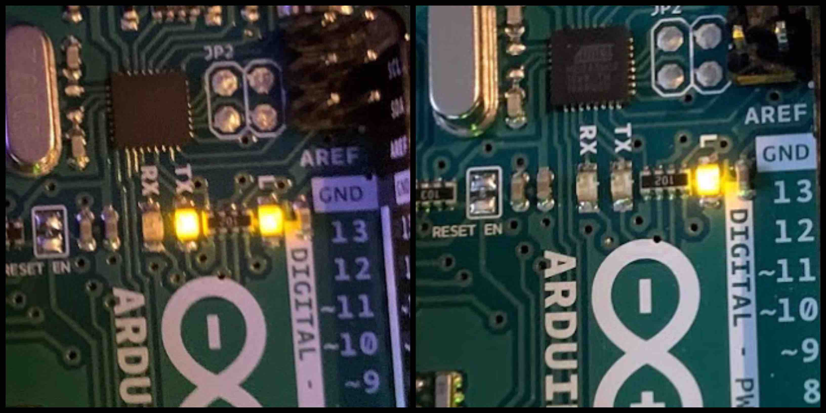
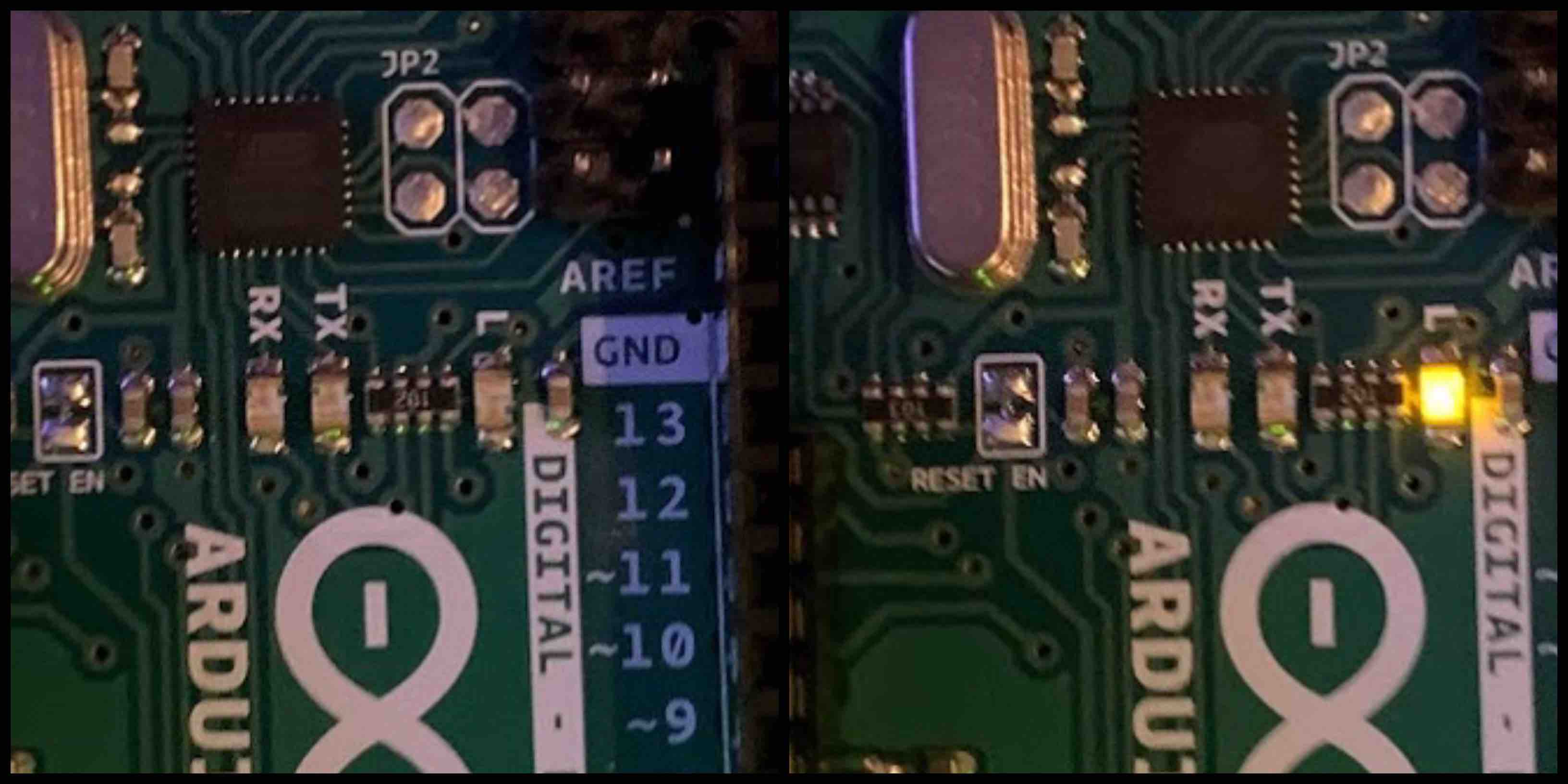
With everything connected I uploaded the code to the Arduino. The Arduino then responded by blinking. Before the Arduino is programmed two of the LEDs shine. When the program is uploaded one LED blinks on, then off, then on again.
Arduino Blink Code
// the setup function runs once when you press reset or power the board
void setup() {
  // initialize digital pin LED_BUILTIN as an output.
  pinMode(LED_BUILTIN, OUTPUT);
}

// the loop function runs over and over again forever
void loop() {
  digitalWrite(LED_BUILTIN, HIGH);   // turn the LED on (HIGH is the voltage level)
  delay(1000);                       // wait for a second
  digitalWrite(LED_BUILTIN, LOW);    // turn the LED off by making the voltage LOW
  delay(1000);                       // wait for a second
}
Arduino Phototransistor and LED
For this exercise I wanted to try something that I would be able to apply to my final project. Knowing I wanted to do a solar panel light, and pulling from successful projects that are similar I decided to test the functions of a phototransistor. Using a breadboard, Red LED, phototransistor, Arduino and the code bellow I programmed the function to result in a change in the intensity of the light what interacting with the phototransistor.
Arduino Phototransistor and LED Code
int convertValue; // define a variable to save the ADC value
int ledPin = 9; // the number of the LED pin

void setup () {
    pinMode(ledPin, OUTPUT); // set ledPin into output mode
}

void loop () {
  convertValue = analogRead(A0); // read analog voltage value of A0 port, and save
  // Map analog to the 0-225 range, and works as ledPin duty cycle setting
  analogWrite(ledPin, map(convertValue, 0, 1023, 0, 255));
}
From Youtube
Self Made Board & Programmer
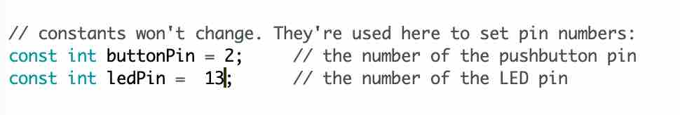
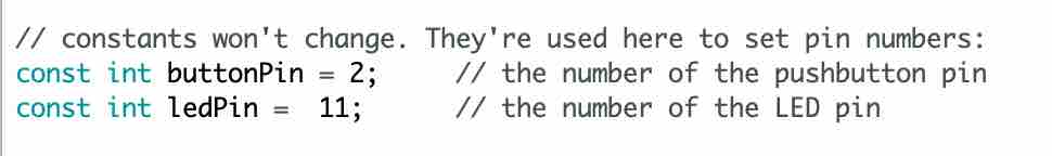
I attempted to used the Arduino blink code to program my self made board. I changed the pin numbers to match the layout to my board and attempted to upload the code.
This however did not work due to the errors connecting to my programmer. I plan to further investigate.
Upon further investigation I did find a function in the Arduino program that allows the user to upload code using a programmer. This however also resulted in errors loading to the homemade board. I can see both ports listed in the serial log, however I need to resolve the errors.
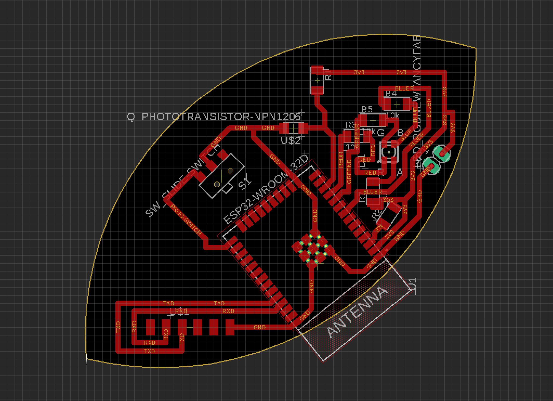
Self Made Board - Phototransistor to RGB LED
My Board and Changing Colors
My board was cut and soldered to be used with the ESP32 WiFi capabilities. Using the WiFi connection I am able to change the colors of the RGB LED with the application interface.
PMW and How it Changes the Color
Using the RGB LED and PWM pins the color can be controlled and changed. The colors on the R, G and B pins of the LED are controlled when assigned to PMW pins. PMW stands for pulse width modulation and is explained below. I also have this information in my output week.
This changing of the RGB values within the LED is via coding and controlled with PMW pins (pulse width modulation). Arduino does a really great job explaining the concept. In short specific pins on a microcontroller are assigned with the function of being a pwm pin. As long as the RGB LED pins are assigned to the PMW’s then they should be able to be coded with a value ranging from 0-255. Each of the R, G and B can be changed within that range. In output week my code includes RGB_color(100, 0, 255) which lists a series of 3 values, the first representing R, the second representing G and the final representing B. Each of those represent a percentage relating to that specific pin. This percentage stands for the length of the pulse being provided through the microcontroller and appears to the user as brightness in the LED. When these percentages are adjusted and mixed with the other two they emit different colors.
- As a note, PWM is a form of controlling the power but when in relation to LEDs it controls the brightness.
Input Readings - Phototransistor
The board I built included a phototransistor to gather light readings. I used the phototransistor that reads visible light. This is then programed to control the output.
Output Devices - RGB LED
The output device is an RGB LED that I also built into the circuit. This was designed to react to the input of the readings for the phototransistor. As more light came into the phototransistor the RGB LED turns off. When less light readings come into the phototransistor the light turns on. This triggers the light to glow at night and charge during the day.
Example Recording
// Written by Alecia Gorski

//uses a phototransistor reading and transmits to the esp32, this then turns the led on or off
//based on the readings received from the phototransistor

//Fab Academy 2020 (July)


int photoTran = 27;
int reading = 0;
int LEDpin3V3 = 2;
int LEDpinR = 26;
int LEDpinG = 25;
int LEDpinB = 32;

void setup(){
pinMode(photoTran,INPUT);
Serial.begin(9600);
pinMode(2, OUTPUT); //sets the digital pin 2 as output
pinMode(26, OUTPUT); //sets the digital pin 26 as output
pinMode(25, OUTPUT); //sets the digital pin 25 as output
pinMode(32, OUTPUT); //sets the digital pin 32 as output
}

void loop() {
reading = analogRead(photoTran);
Serial.println(reading);
delay(100);

if (reading > 3800) {
  digitalWrite(LEDpin3V3, LOW);
  digitalWrite(LEDpinR, LOW);
  digitalWrite(LEDpinG, LOW);
  digitalWrite(LEDpinB, LOW);
  //LED should be off during the day
}

else if (reading < 3800) {
  digitalWrite(LEDpin3V3, HIGH);
  digitalWrite(LEDpinR, HIGH);
  digitalWrite(LEDpinG, HIGH);
  digitalWrite(LEDpinB, HIGH);
  //LED should be on during the night
}
 }
This may seem a bit confusing at fist. The code sounds like it should do the opposite of what the videos reaction is. However, I believe this has something to do with the combination of analogWrite and digitalWrite within the code. When uploaded with the HIGH and LOW values switched there was no reaction being recorded.
What I Learned
I learned a lot from interfacing an input device to my microcontroller and how the physical property relates to the measured results. This was the first time I have ever worked with electronics so I came into these assignments with little to no knowledge. I learned that the code you write may not be interpreted by the microcontroller the way you may think. You have to interpret your code as you believe the microcontroller is in order to write it so that the function works how you intend it to.
I learned how a phototransistor works and how the light being received controls the readings seen in the serial port. These readings helped me to better adapt my code to the expected outcome.
When designing the board I learned a lot about the pin functions and how important a pinout guide is. I learned that reading the data sheet is important to interpret what pins should be used for certain functions. Some pins need to be left at low level energy so if it has a function on high the board wont work.
I learned how to use the Arduino software to upload my programs and read the results with the serial port. Being able to use the serial port to interpret the functions of your board is a huge debugging advantage.
Design and Fabrication Process
I was also able to program an input using the potentiometer and that research can be found below.
Research
The assignment was to add an output/input device to a microcontroller board you’ve designed, and program it to do something. However, under the current COVID-19 quarantine and shut down we do not have lab access at the moment.
In place of the device I made I used an Arduino and breadboard set up with the other necessary components.
Arduino RGB Color Control
Again I wanted to apply this assignment to my final project Leaf Light. Knowing I want to use an RGB LED so that the user can change the color of the light being admitted through an application on the phone, I decided to test a circuit for this.
Using the Arduino, potentiometers, RGBLED, resistors, and the Arduino software to upload the code I tested the function and was very pleased to see the light changing color with each turn of a potentiometer. I want to apply this function to my final project through the use of a microcontroller.
Each potentiometer is connected to a separate R, G, or B pin for the LED. When the potentiometer is twisted it controls the value equivalent to the scale of 0 to 255. Depending on the position of each potentiometer the color of the R, G and B mix to make the color displayed.
Arduino RGB LED controlled by rotary potentiometers Code
int redPin = 11;
int bluePin = 10;
int greenPin = 9;
int redIn = 0;
int greenIn = 1;
int blueIn = 2;
int redVal;
int greenVal;
int blueVal;
void setup() {
// nothing to do here
}
void loop() {
redVal = analogRead(redIn);
greenVal = analogRead(greenIn);
blueVal = analogRead(blueIn);
// analogRead returns a value between 0 and 1023
// analogWrite wants a value between 0 and 255
// That means we need to map the input range to
// the correct output range.
redVal = map(redVal, 0, 1023, 0, 255);
greenVal = map(greenVal, 0, 1023, 0, 255);
blueVal = map(blueVal, 0, 1023, 0, 255);
analogWrite(redPin, redVal);
analogWrite(greenPin, greenVal);
analogWrite(bluePin, blueVal);
}
Explaining the Code
This code was uploaded to the development board using the Arduino IDE. The development board is set using an ESP32. The int commands at the top of the code assign values to each pin number. This allows the coder to communicate with the microcontroller. These are then used to assign the values to the analogRead() and analogWrite() command. The analogRead() control is determining the voltage between 0V to 5V that is being supplied. The analogWrite() control is determining the pwm number between 0 and 255 that controls the strength of the color being emitted, or as mentioned above the pulse. The map value equates to the function of the potentiometers control of the R, G, or B value.
Arduino Potentiometer and RGB LED
Files
Files used in Input Week can be found in the File Zip for the final project.