16. Molding and Casting
This week I worked on molding and casting applications for my final project. I want to create a mold to use when forming the soft light filter on the top of my leaf light. I plan to mill a wax block with the CNC machine. This wax block will then be used to make a silicon mold. I can then cast the part I need from that mold, keeping in mind that I will need a porous material to use with the Vacuum Former.
For the group site I contributed the documentation for the experiences with the material I used to make my mold, as well as the use of both dry-stone and hyro-stone as casting materials.
Useful links
Research
For this assignment we were challenged to read and test many different materials. As we began our process we found many of the supplies dried up. It was explained that each material, when open, has a very specific shelf life. When air is able to access the material it will harden over time. It is the process that both creates the parts and solidifies the material. If the material does not get used it then goes to waste in a short time.
Digital Mold Design
I had to start this week by creating my mold design. Since my leaf light design was already dimensionally accurate in my fusion design file I used this as my starting point. In the first version it was very clear I was a bit confused on whether to make a positive of what I needed of a negative. In the first model mater I created the negative. This was incorrect.
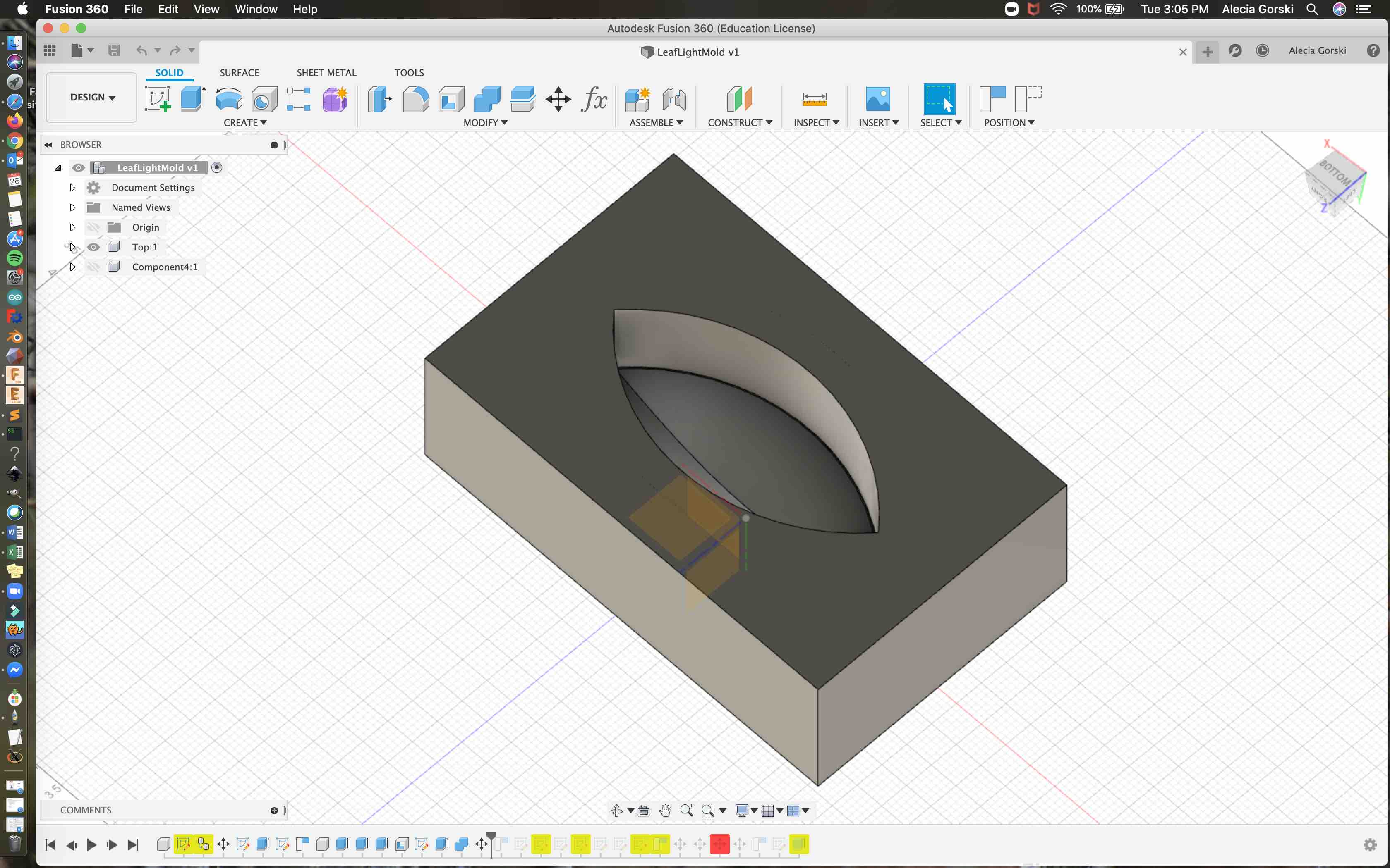
In order to have a was CNC mold for the silicon it has to be a positive of what you plan to cast in the end. I began to redesign my overall part in order to make the positive form. I went back to my design and isolated the frame. My goal is to create a casting I can use to vacuum form the soft light filter that fits into the frame. I extruded a box on the bottom of my frame to represent the bottom of the wax mold that will be left. I then used a similar process to extrude the top of where the soft light filter should fit.
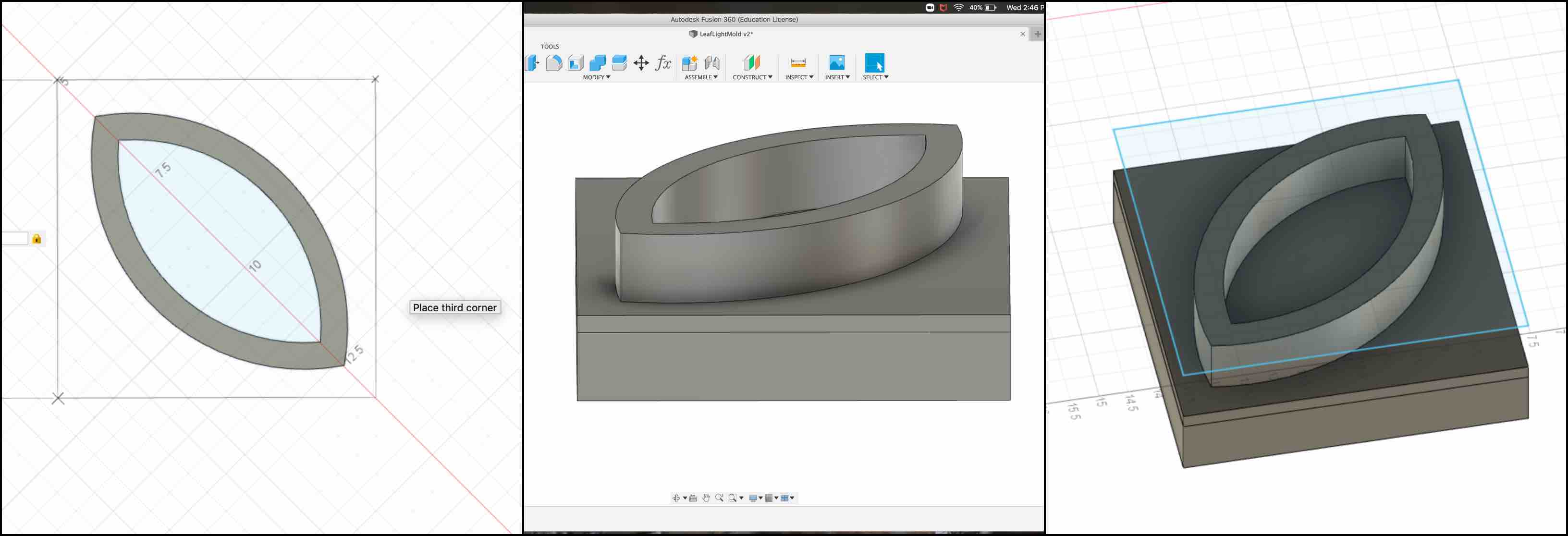
I rounded the top to get the surface look I desired.
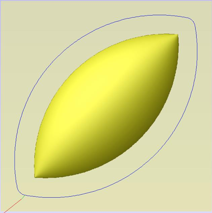
When this was complete I extruded another box around the whole part. This would represent the top of the wax block where I would be removing material. When this was complete I selected my frame and extruded it down one inch.
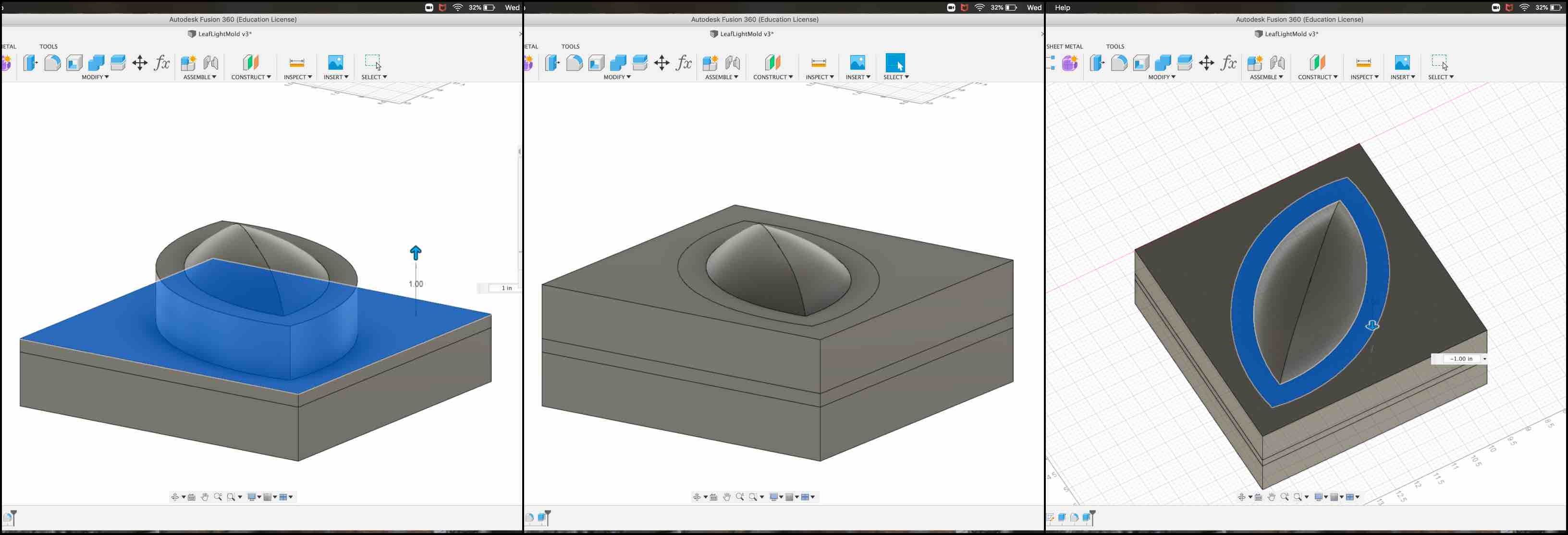
This removed the frame from the box created around it, leaving the molding material desired floating as an island in the middle. This is what will create the silicon mold. I then finished the design by creating the moat around the outside. This was explained as a necessity to be sure the silicon is able to cover all pieces.
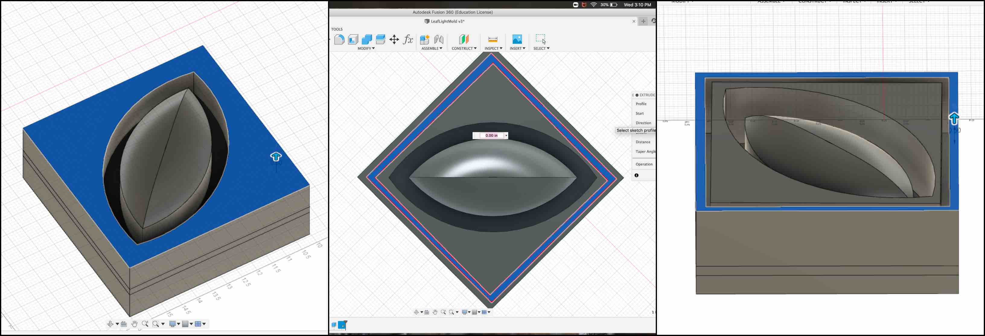
- Note: After milling this from the wax I did realize that my design accommodated one too many moats. The extra moat on the outside of the design was not needs and this was compensated for in the final design to be sure not to waste materials.
Aspire
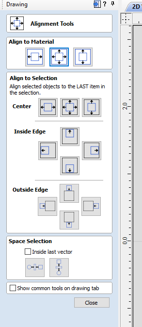
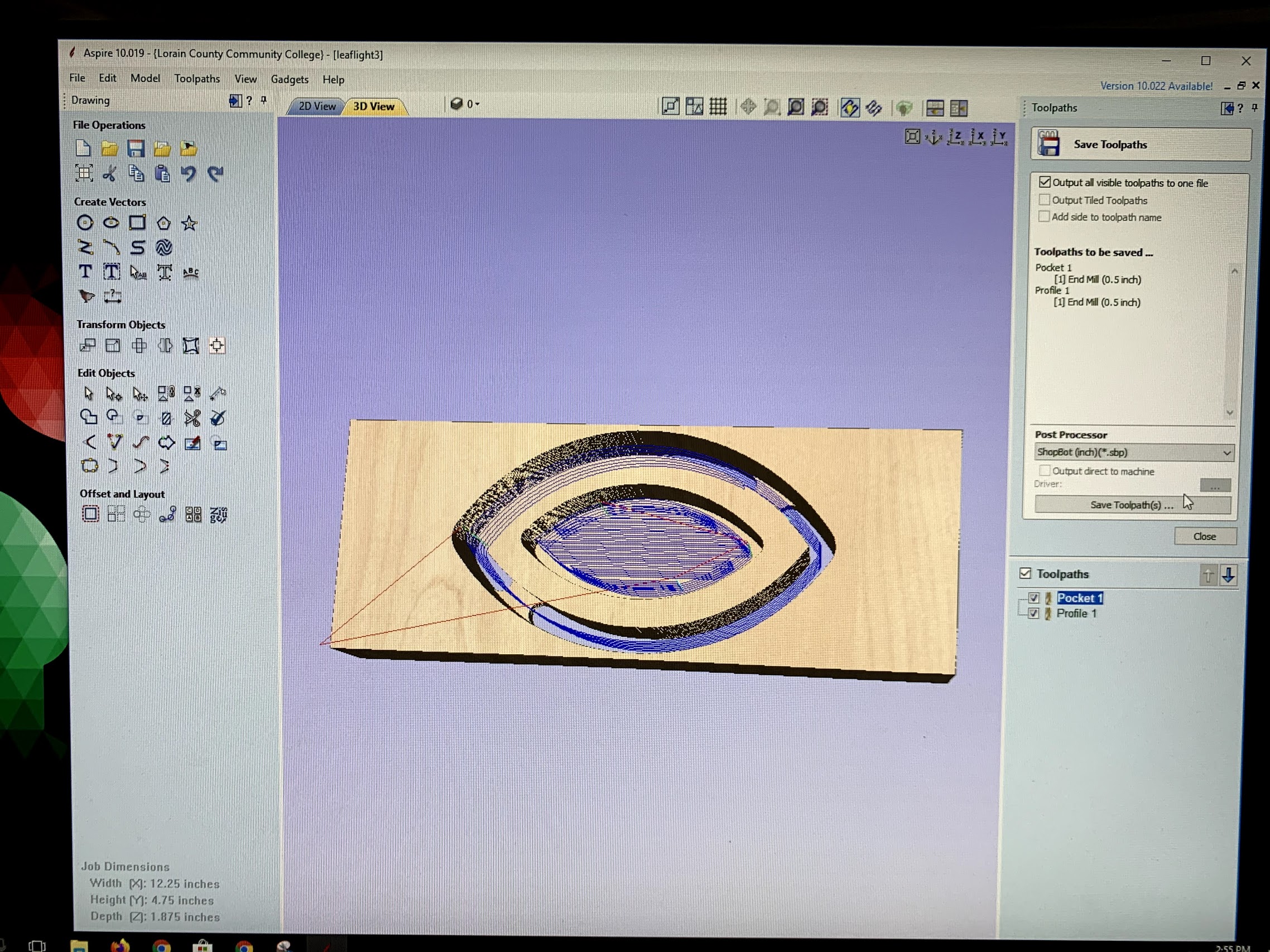
With my 3D model made correctly and to scale I had to move the shapes over to Aspire. Aspire is the program we use with our CNC Machines. More information on the CNC machining process is found in Make Something Big! Week. Aspire is not directly compatible with Fusion 360, so I had to first import my shapes into CorelDraw as .dxf files. I could then import this file into Aspire. I used the Alignment tool, which can be seen in the screen shot below, to be sure everything was centered.
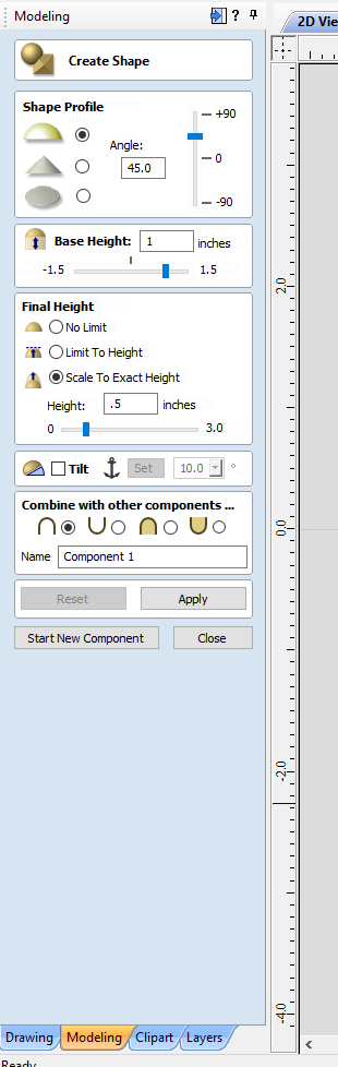
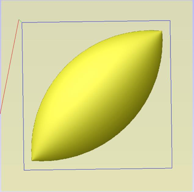
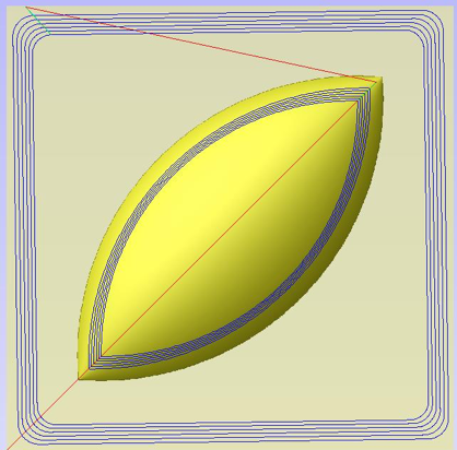
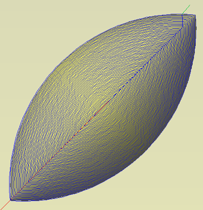
I then used the 3D option in Aspire to create a Shape. This allowed me to select the vector path I would like to apply the shape to. Choosing my middle bloom I applied an angled dome shape. I then scaled it to two inches and created the new component. In the 2D view it appeared as a gray scale shape.
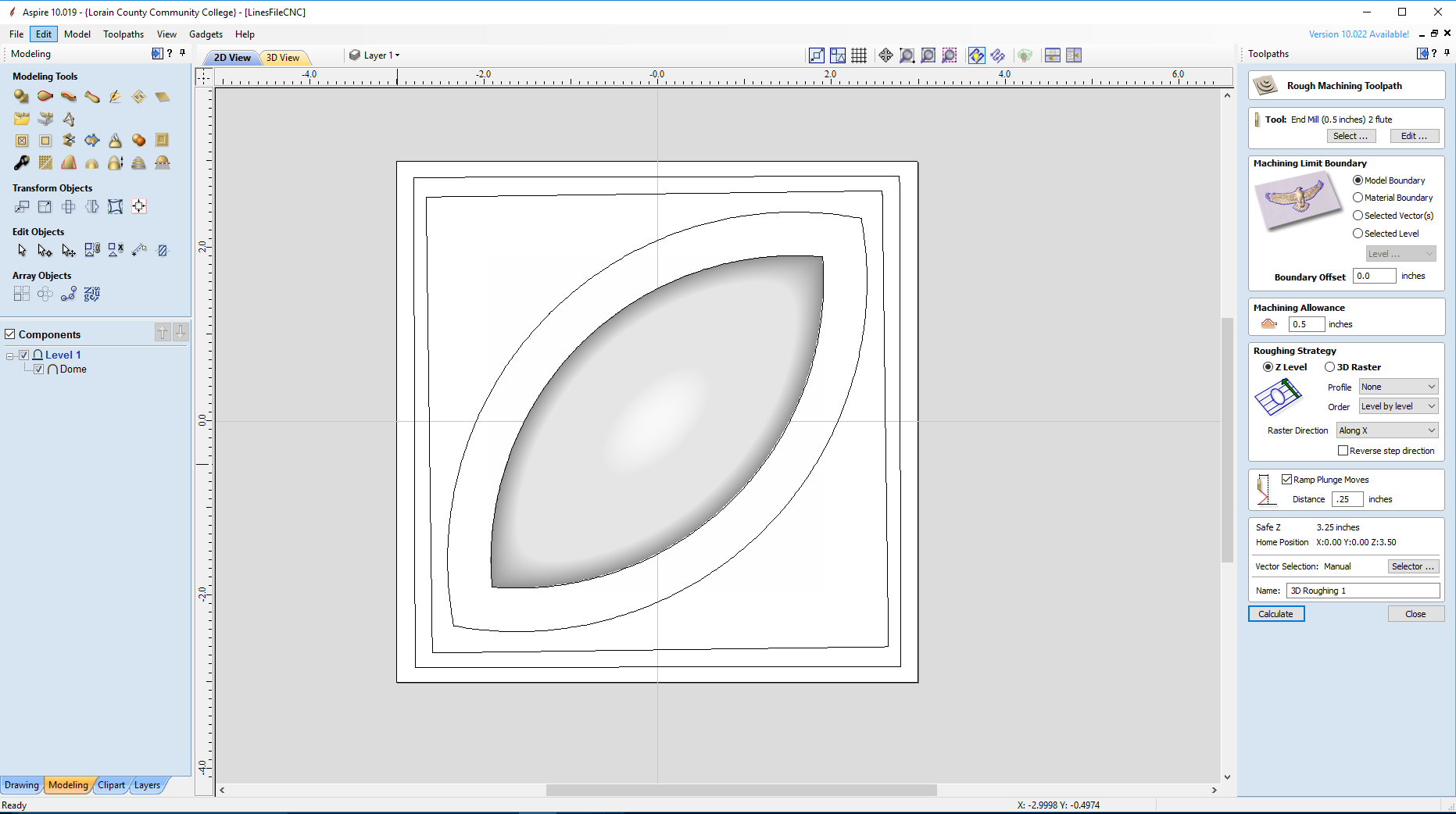
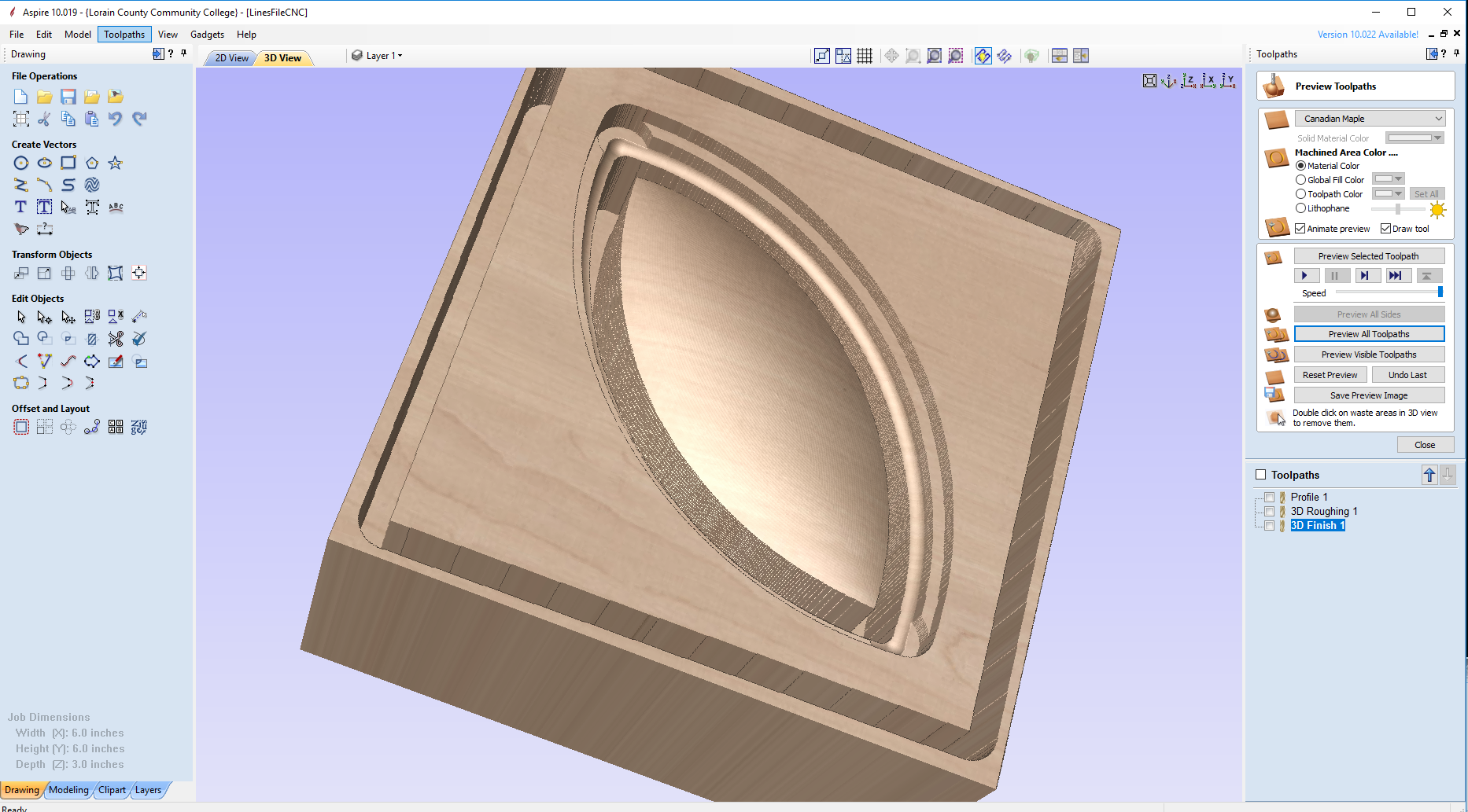
I applied the tool paths and previewed them to be sure it worked correctly. I was pleased overall with how the preview looked so I saved the tool paths to my flash drive to use with our CNC router.
Tool Information as SUggested by MIT
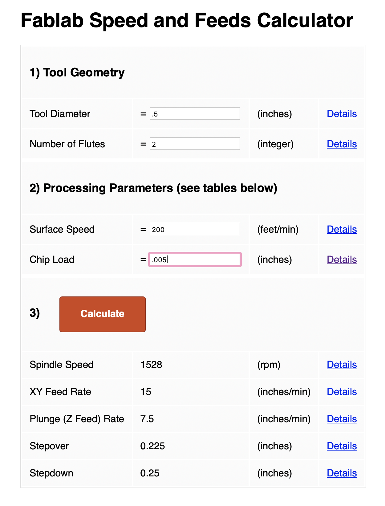
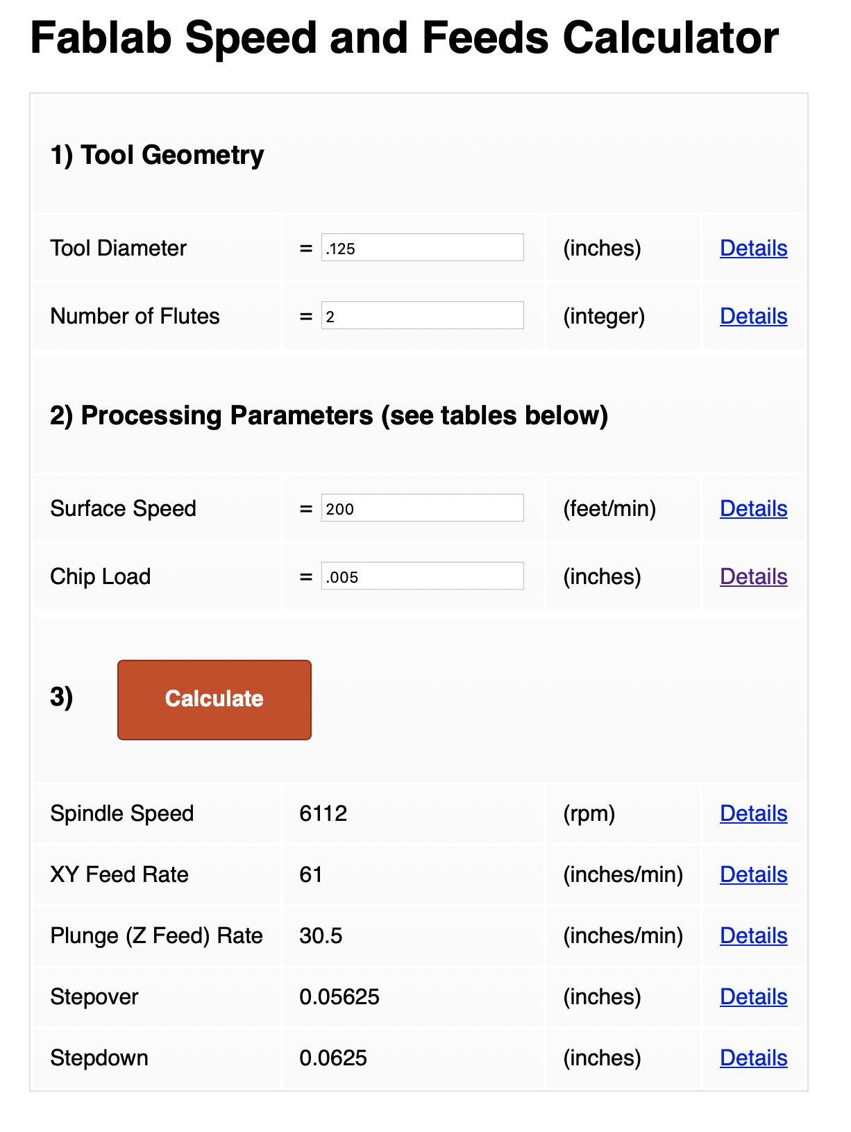
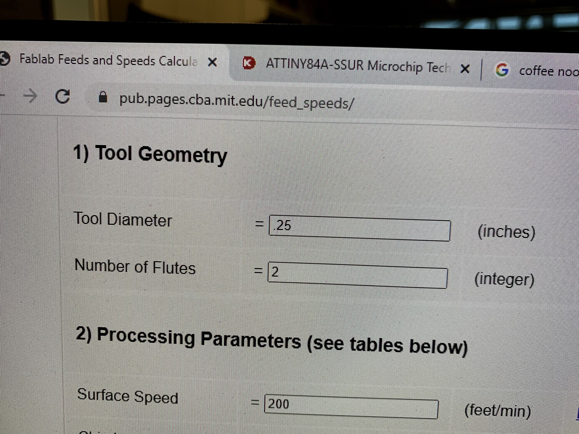
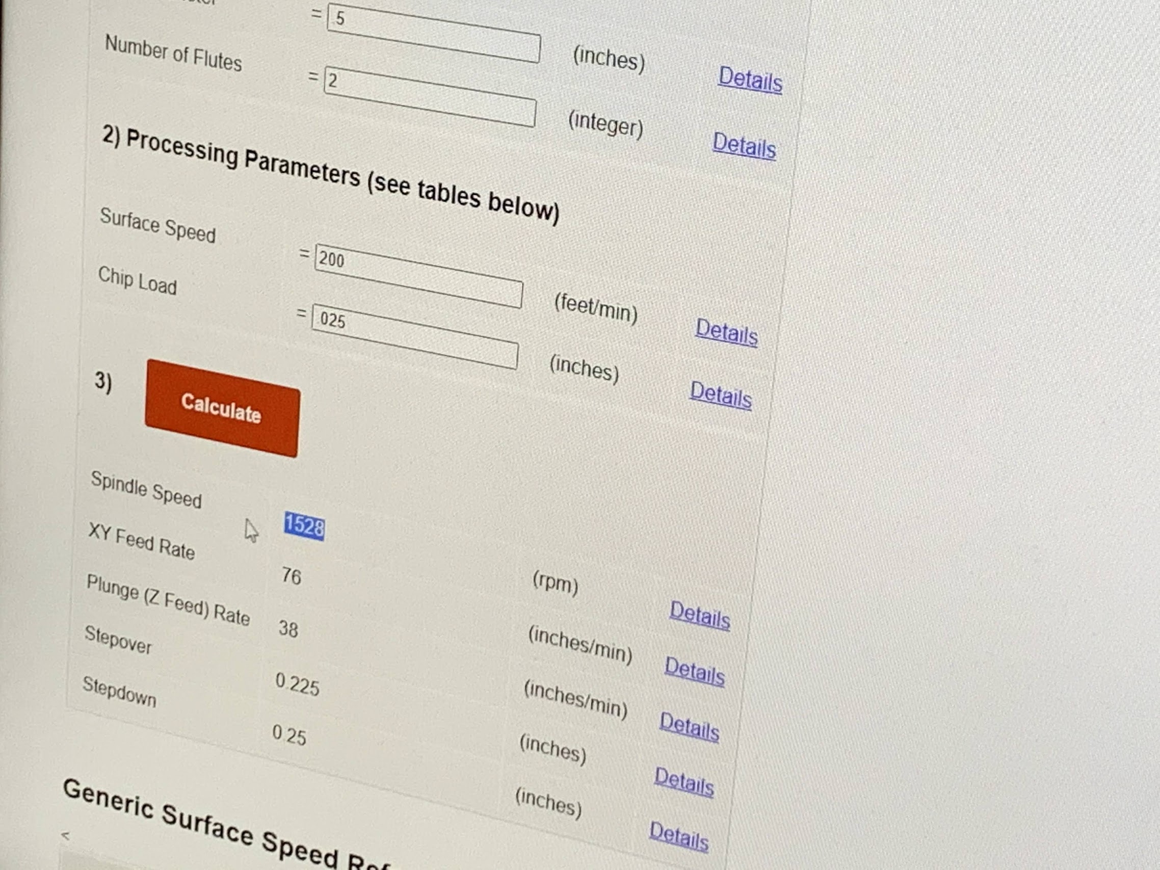
I used the Fablab Speed and Feeds Calculator to determine the settings I should use. I then used these setting when manually applying the spindle speed.
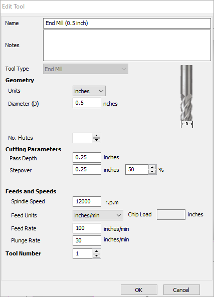
Tool: 1/2 inch End
Feed: 15 in/min
Speeds: 1528 rpm
Plunge Rate: 7.5 in/min
Operation: Roughing Pass
MIT Suggested Tool Settings:
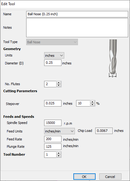
Tool: 1/8 inch Ball Nose End Mill
Feed: 61 in/min
Speeds: 6112 rpm
Plunge Rate: 30.5 in/min
Operation: Finishing Pass
MIT Suggested Tool Settings:
My Aspire Tool Settings
My final design file was compiled of 5 separate cut profiles. the 3D dome was created in aspire and was assigned to its own tool paths as well as the paths to cut the shape out. The 5 Profiles are listed below with the details on the feed and speed settings. I used these profiles with my Fab Lab Machines. For the spindle speed I used the MIT suggested settings. There is some variation with the 1/2 in end mill and I believe this is due to the changes in cut depth for the necessary passes. They are also divided due to the order in which they were to be completed.
Profile 1:
This was generated by Aspire. I used this profile to cut the moat on the outside of the leaf shape. I used the 1/2 in end mill.
Profile 2:
This profile was generated to use the 1/2 in end mill. This cut was completed to create the start of the dome. This profile removed the outer boarder of material so that the roughing and finishing passes can access the correct material. It also clears the wax so that my silicon rubber mold can fill the are and shape the overall piece.

Profile 3:
This Aspire cut profile was created to cut the outside moat. It wasn’t until after milling I realized the square was unnecessary. It added an addition moat to my project.
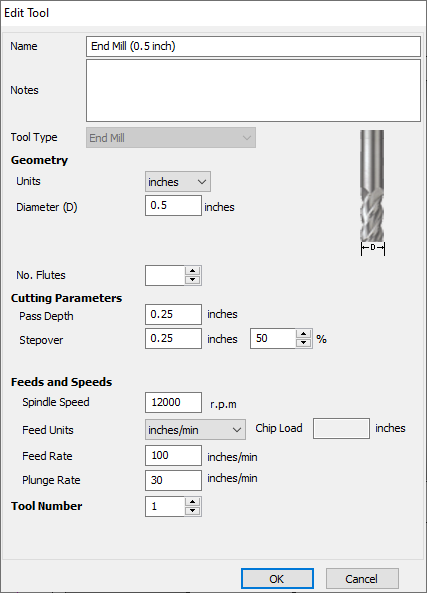
3D Roughing:
This profile was used with the wax block on the final ShopBot cuts. This profile made the rough steps. This step helps to remove a mass of material that is not used in the smoothing stage. This is done using the larger 1/2 in end mill to speed up the process.
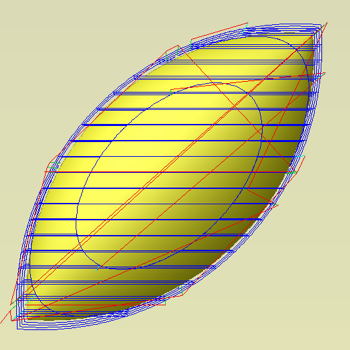
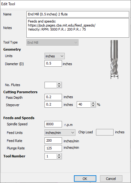
3D Finishing:
This was the last required tool path. This tool path was completed using an 1/8 in ballnose bit.
- Here there was a mistake made. The toolpath represents the use of a 1/4 in ball nose. However I loaded and used an 1/8 in ball nose for the finishing pass. This was a mistake and was discovered after the process was complete. There were no apparent issues after the cut was complete but it does not show consistency in my documentation. I believe there was no issue visually due to the way the bit function. The ball nose tool cuts with the side of the tool and not from the middle. This combined with small steps allowed all of the material to still be removed.
This bit is smaller and makes smoother cuts. Working from where the roughing pass left off this ballnose bit removed the final excess of material and left the smooth dome shape in the wax.
Mold Materials
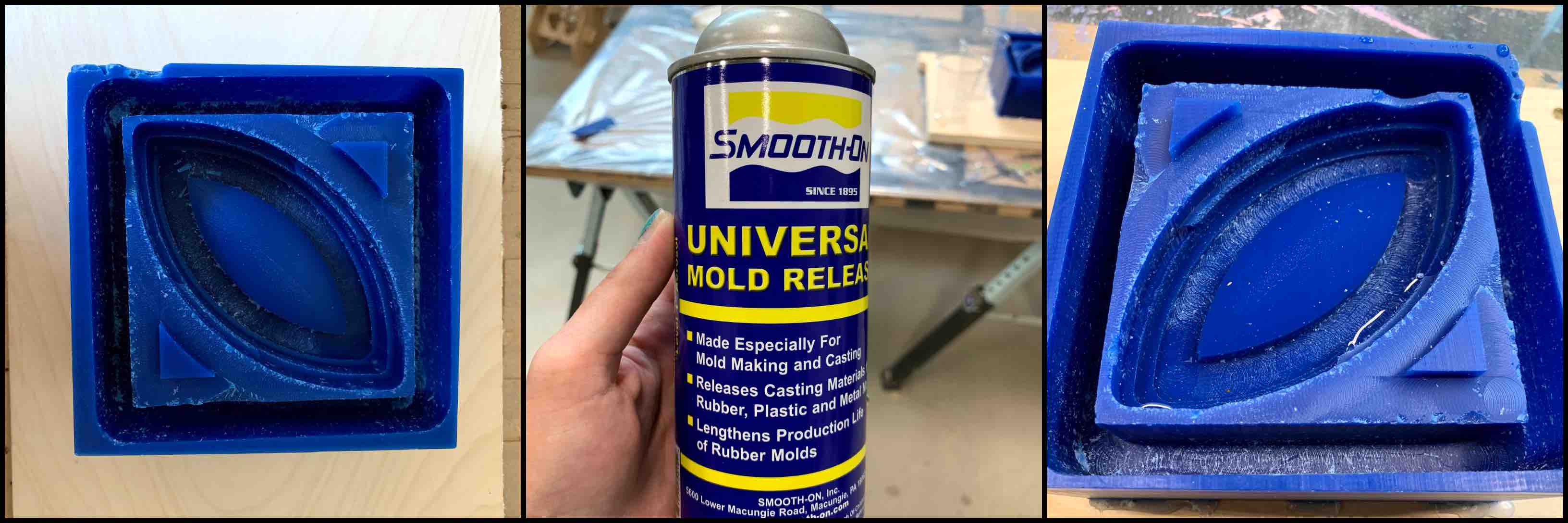
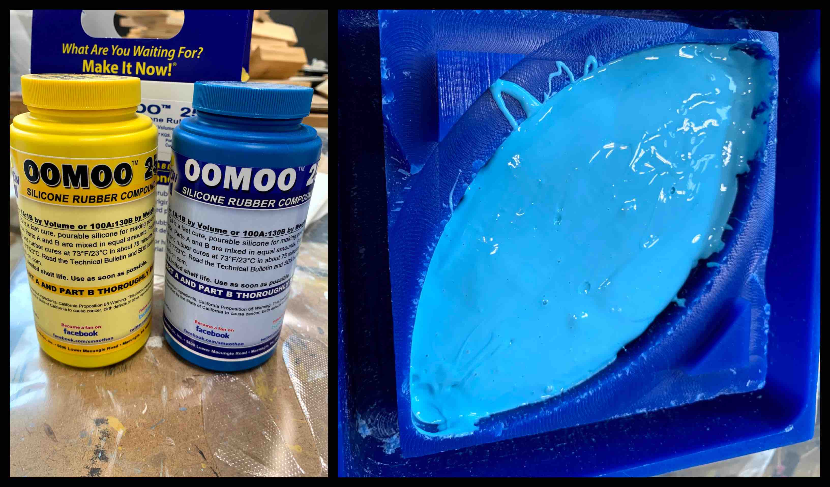
I gathered all the materials I would need to complete this project. I pulled the Smooth-On Universal Mold Release, OOMOO Silicone Rubber Components, the DryStone Casting Media, and my wax block.
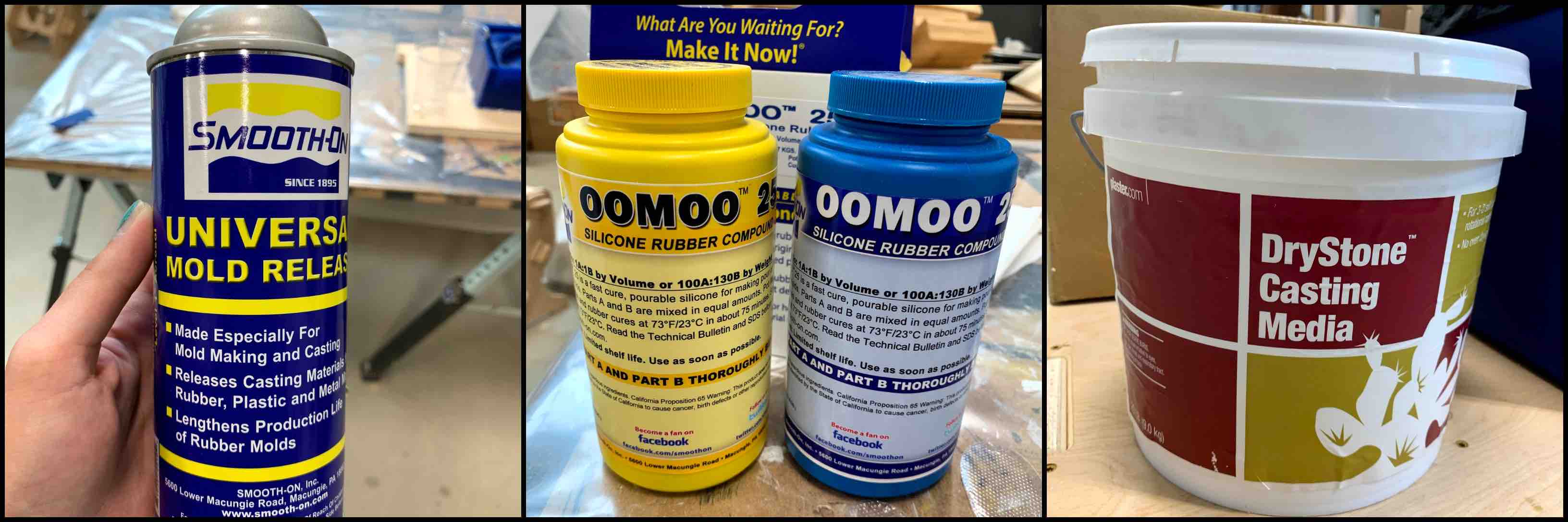
I was sure to review the data sheet for the materials I would be mixing. It is important to be aware of what materials are being used and how they react. Not only with themselves when mixed but also how each component then interacted with the others. When mixing chemical components many different reactions can happen. Often exothermic reactions can cause heat to effect the surrounding materials. This can be very dangerous. Materials also have a setting time. After mixing materials for use you want to be sure to use each material before it begins to set. This can cause complications otherwise.
Creating Wax Mold
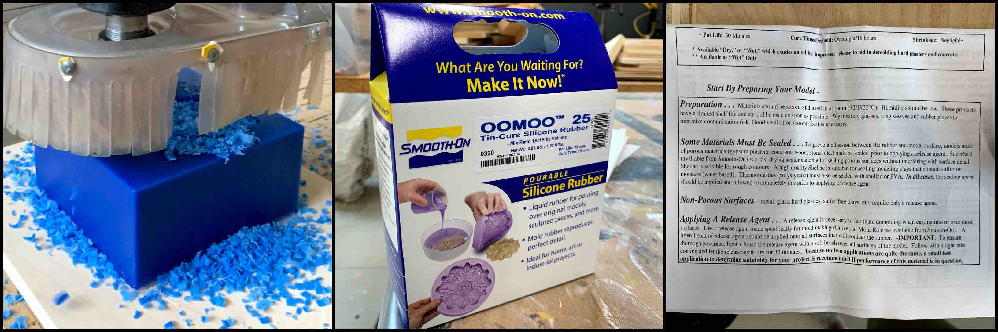
I used the ShopBot CNC Router in our messy lab setting to machine my wax. I used the tooling information I placed into Aspire, along with the information about the material being used, and plugged it into a speed and feed rate calculator on-line supplied by MIT. This supplied me with the correct spindle speed and feed rated for my CNC process.
I ran a variety of tool paths. I used a half inch end mill to mill out the moats and all the extra material. This was a stronger end mill to remove the mass material that was not being used.
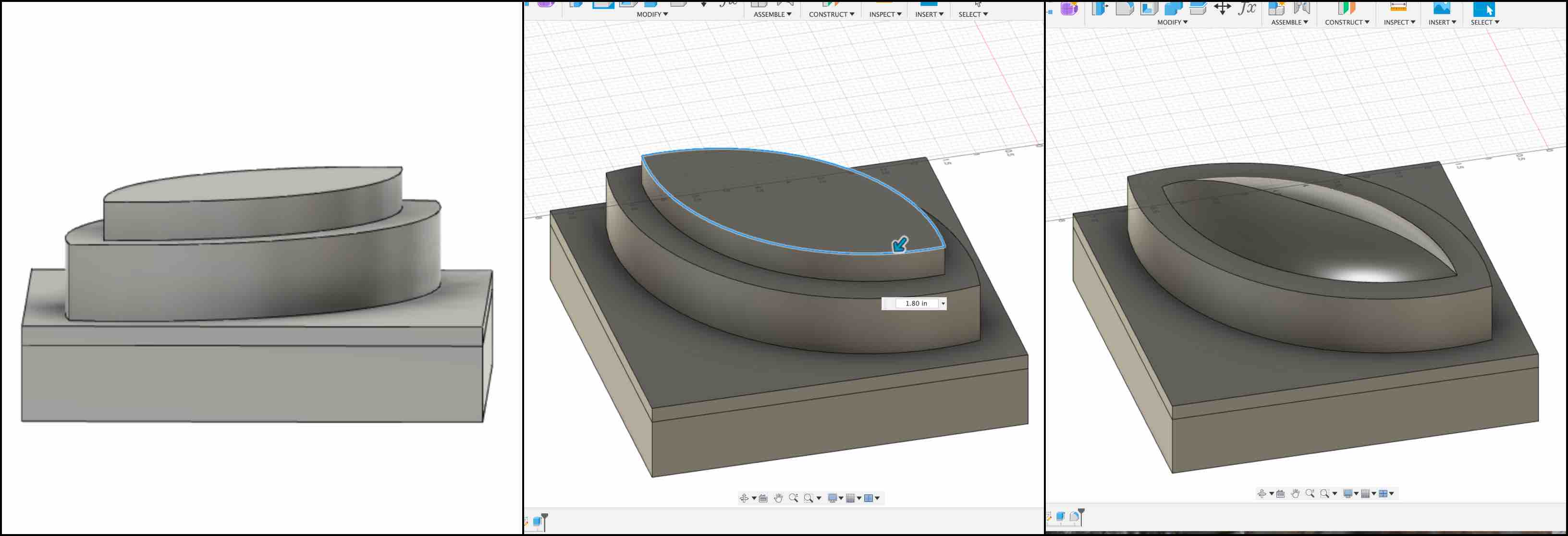
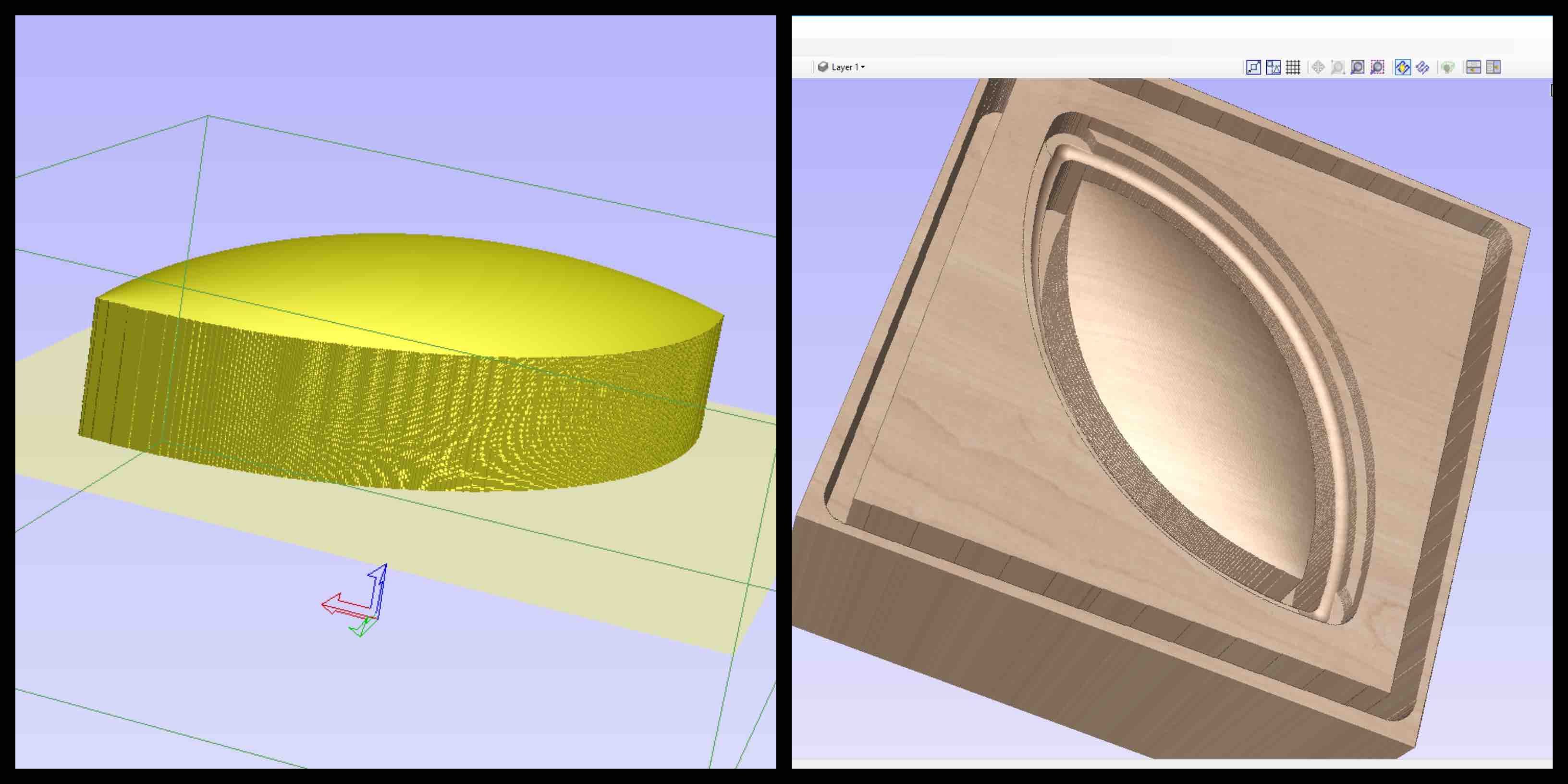
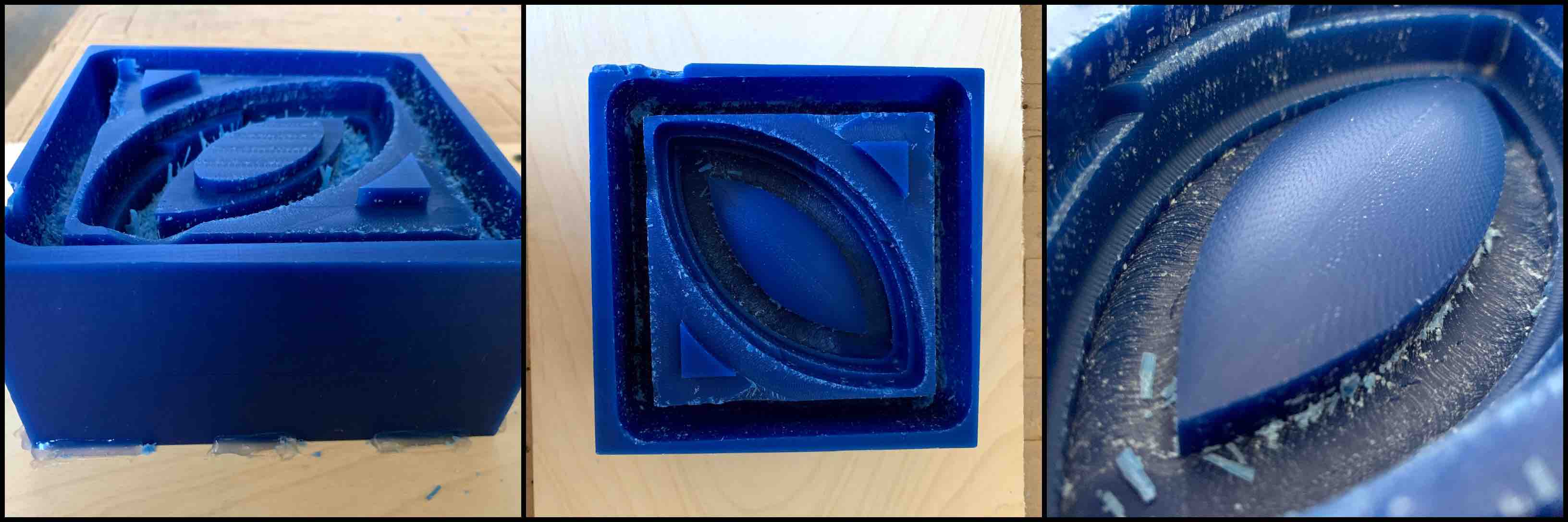
Rough Cut vs. Finishing Cut
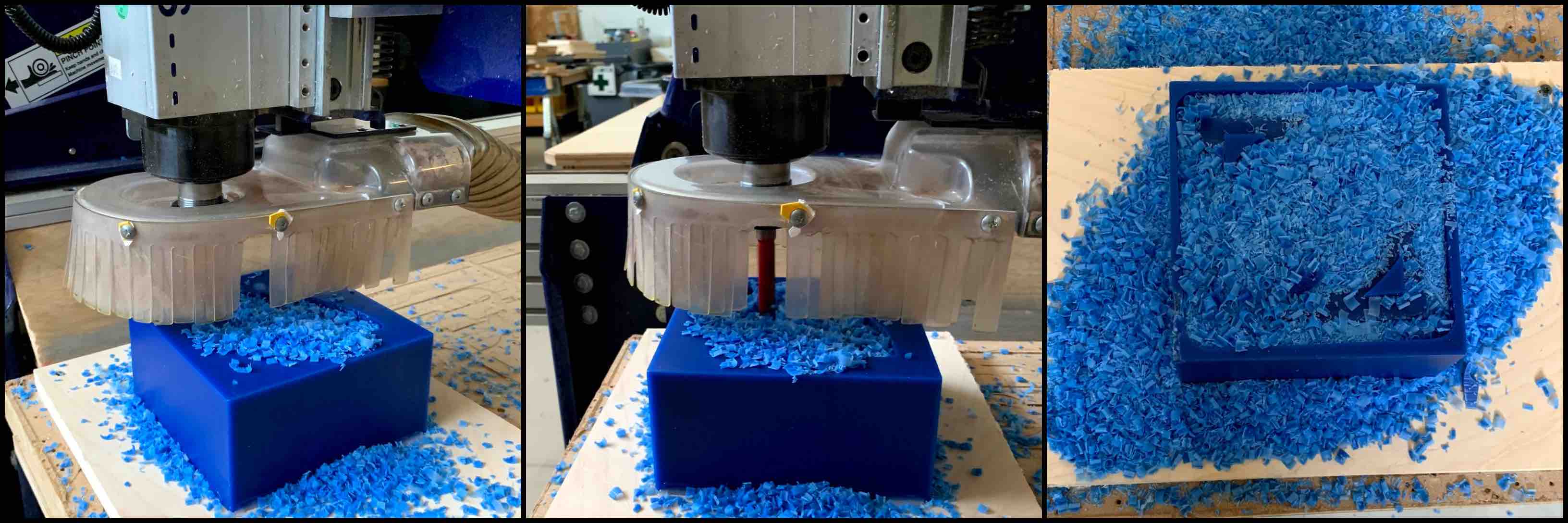
I then used the eighth inch ball nose end mill for the roughing pass and the finishing pass. The roughing pass it the first pass used when created multi axis mills. Having the dome on the top I needed a multi axis milling cycle. In the example below the first picture is the rough cut. You can see the sharp harsh layers. In the second and third photos you can see where the extra axis motions smoothed over the dome with the finishing pass.
Molding Silicone in Wax
With my wax mold created I was then able to start my Silicone molding process. I started by applying the universal mold release. This helps to remove the silicone from the wax. It needs to set for at lease 5 minutes before the wax it used.
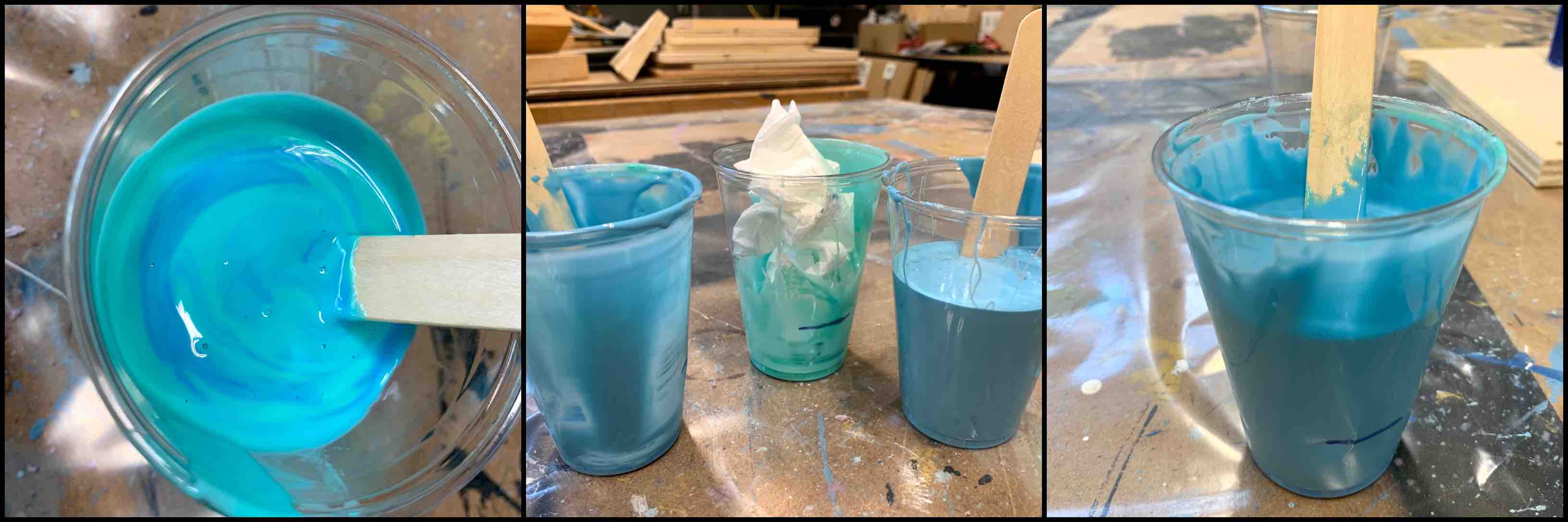
Being sure to protect the surface and work areas being used, the table is covered in plastic. Using water I estimated the amount of silicone I would need to mix. It is always advised to make a small amount more than what you think you may need. This is to ensure you have enough material to fill the whole mold. If you do not, many time the material is not forgiving enough to allow addition mixing of materials to add. If you would attempt this the setting times would not match up and the materials may separate.
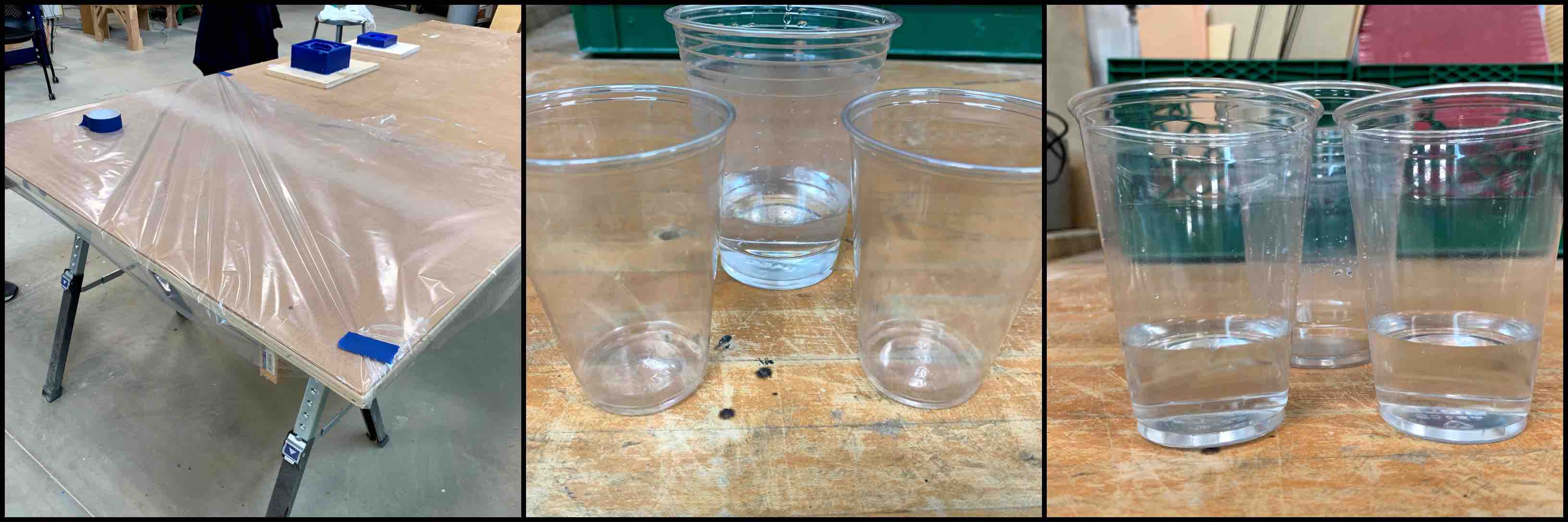
Once the cups were marked I was sure to dry them completely. Water should not be mixed in any of the compounds being used. The OOMOO silicone compounds were two different colors. Using the marked cups I poured equal amounts of both compounds into separate cups. I then combined those into one of the cups already being used. Scraping the tongue depressor along the cup walls and bottom will help to consistently mix both compounds together.
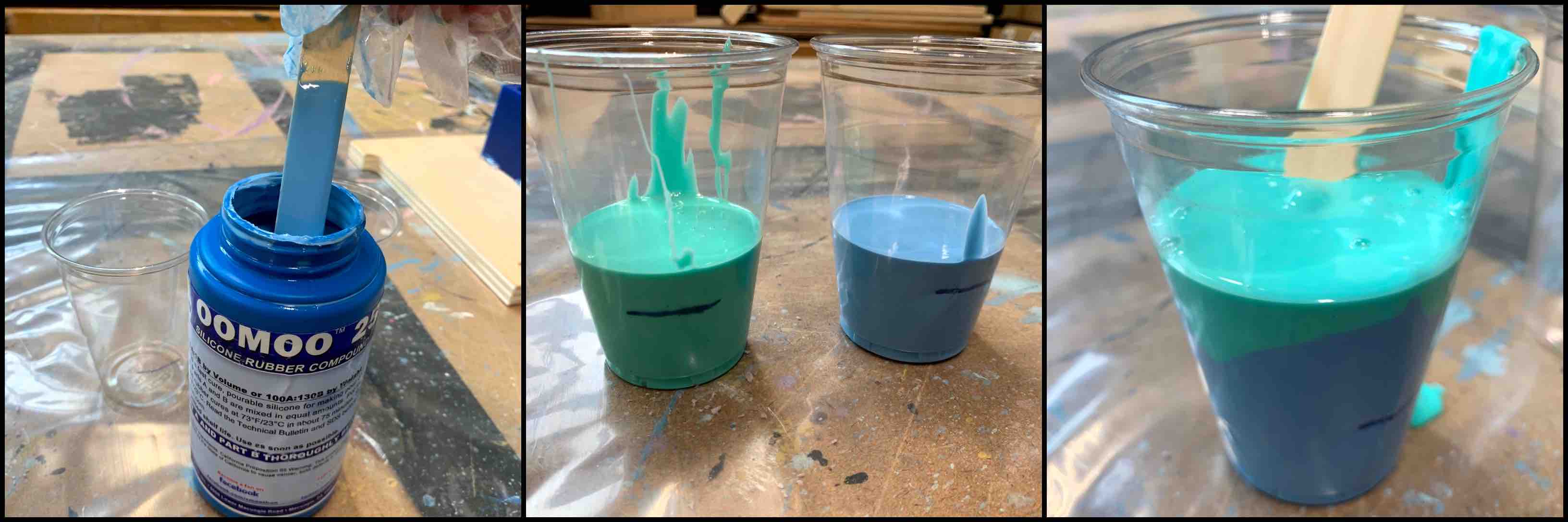
Once the final material is completely mixed to one solid color I moved it into a new cup to be sure that only fully mixed final compound transfers into my wax mold.
Pouring Silicon Mold
You want to be sure that all bubbles have been brought to the surface of your compound before hand. Let it set for a small amount of time after knocking the cup to the counter a few times. With my compound consistent uniformly all one color I then pour it into my wax mold. Pouring from a higher level allows you to create a thinned drip line. You want to pour it thinned to avoid any additional bubbles. Pouring into a low spot and allowing the compound to fill the mold will help with consistency. Once the compound it added completely you can knock the mold against the table again to bring any final bubbles to the surface and to try and eliminate any inconsistencies.
Removing Silicon Mold
As seen in my video above, my compound began to set before being drained into the wax mold and this caused there to be many different air bubbled that did not make it to the surface.
Casting with Silicon Mold
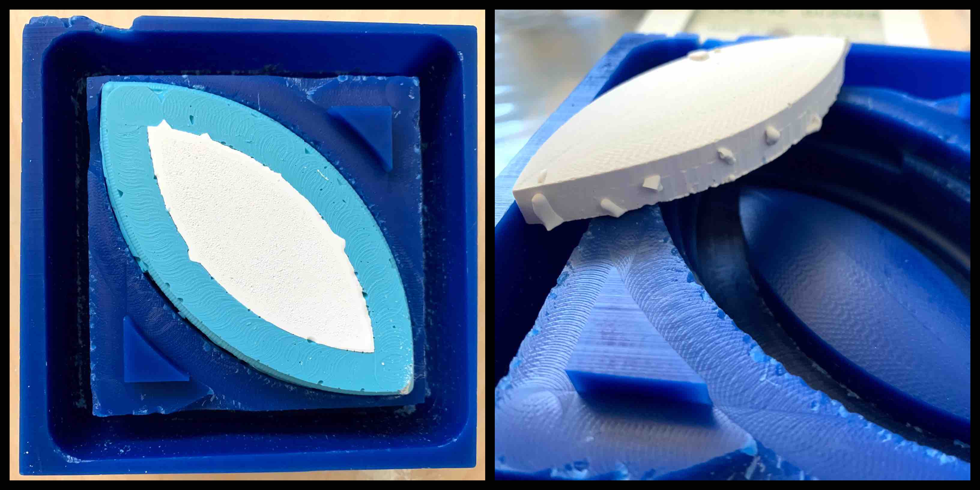
With my silicone mold cured completely I can now use it with the Dry Stone Casting Media. The Dry Stone Casting Media is a beige colored powder that when mixed with water into a pancake batter like substance can be poured into the silicone mold.
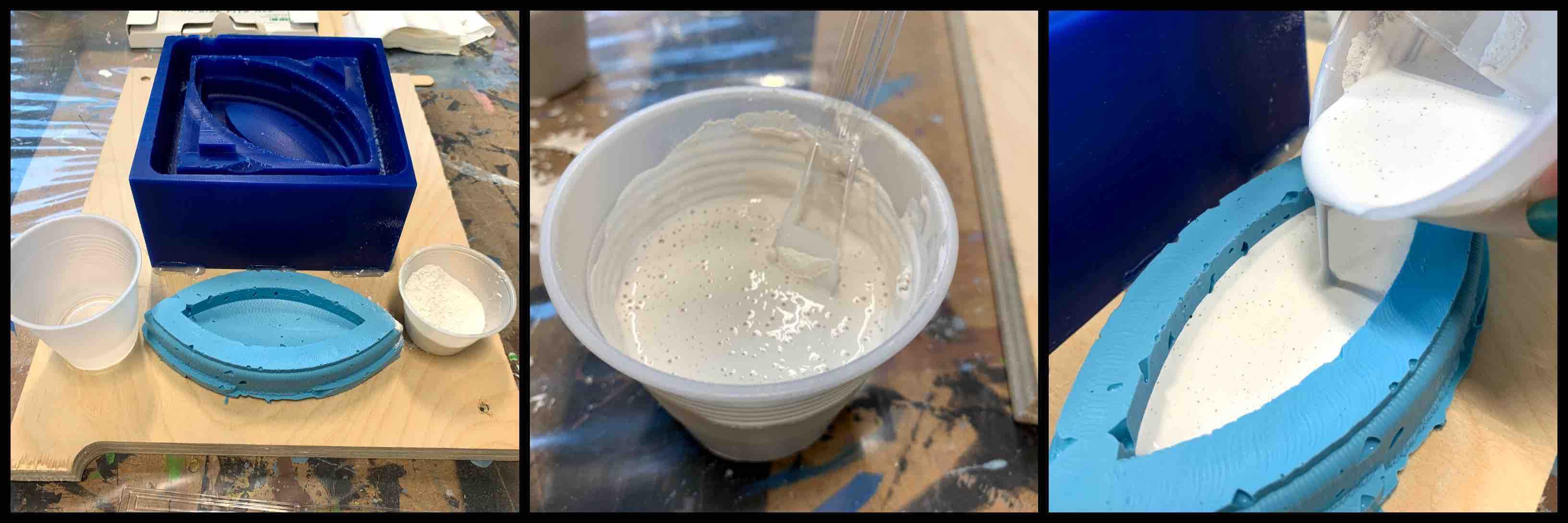
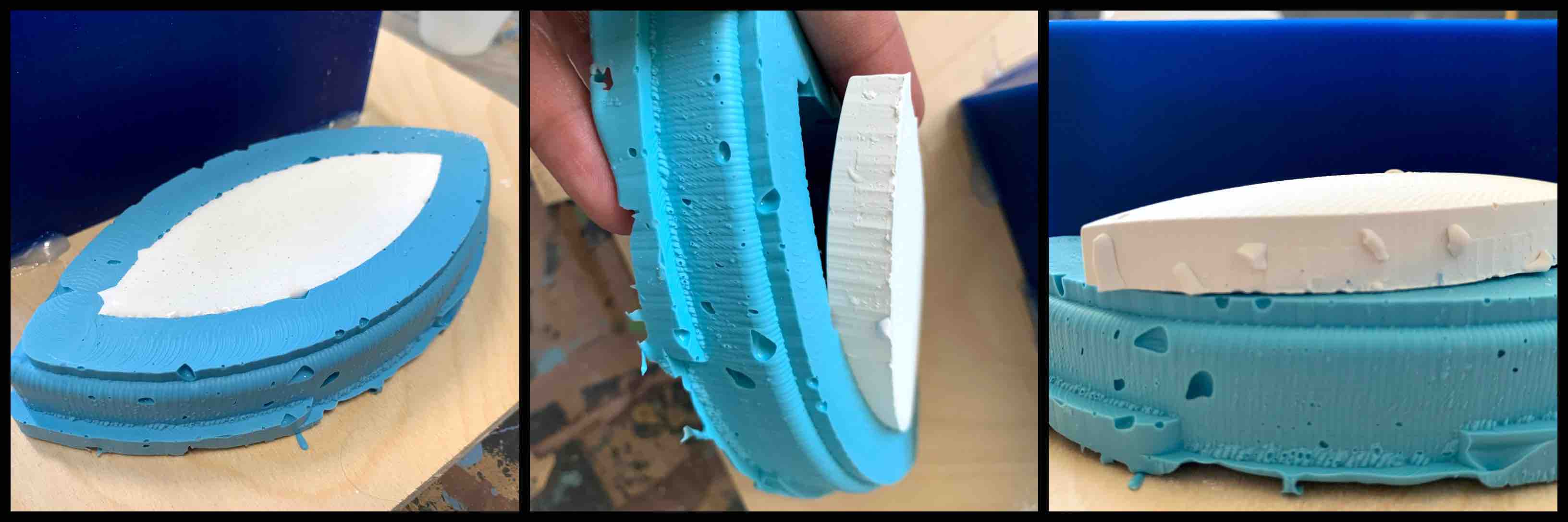
This then is left to harden. When complete the casted piece can be removed from the Silicone Mold. This now reveals the final piece.
Hero Shots
In the end my part did not turn out how I expected. The size was off more than I had planned and there were more air bubbles than I expected. Having never done this process before I was surprised by the number of steps to reach the final piece. The back and forth between negative and positive version was confusing at first but incredible intriguing once the process revealed itself.
I was very happy with my first time completing this process as a whole. The wax machined well and each of my materials reacted the way I expected. I learned a lot from this process any had a lot of fun completing it!