4. Electronics Production
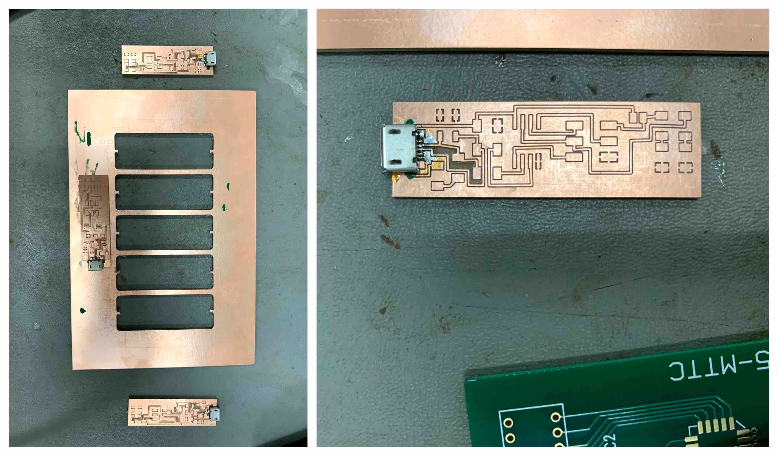
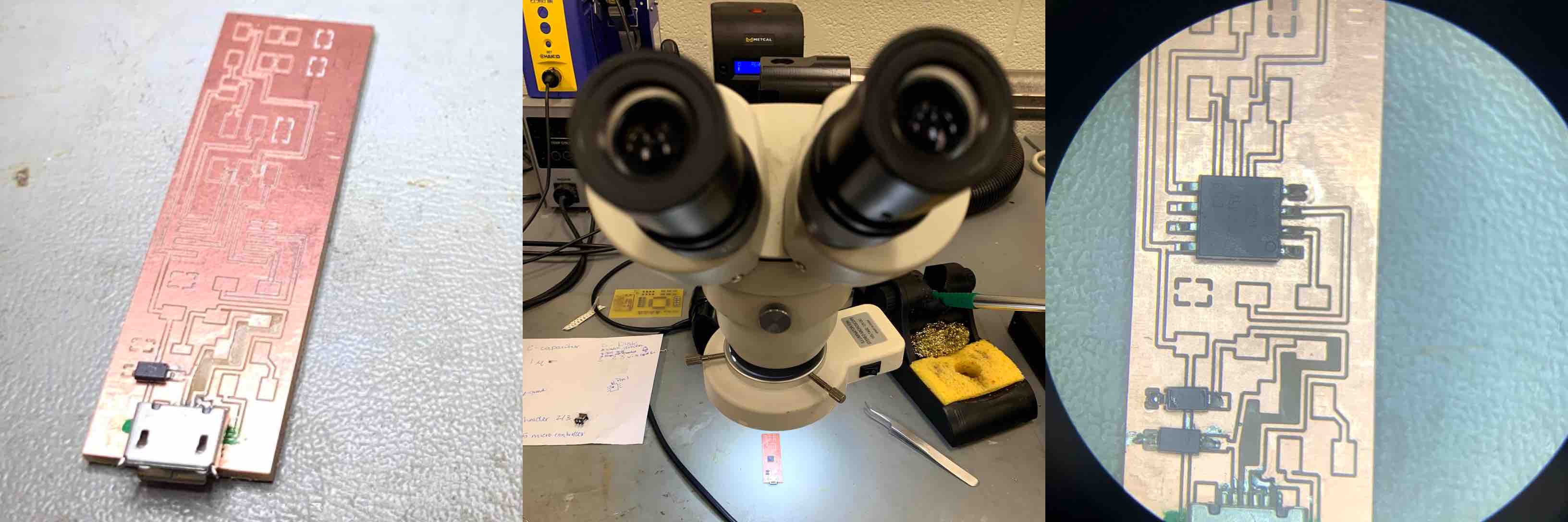
This week I worked on design editing, cutting, soldering, and loading a programmer. A programmer is a board with a connection to the computer (micro USB port) that can be created to load programing and then transfer that to a chip. The chip would then have an application of the programed functions. The programmer I built is a ISP (AVR).
Research
Our research consisted of defining the machines, parameters and functions of creating a programmer from scratch. I used the Brian Board information listed on the Fab Academy web site to create my programmer.
Useful links
I contributed the group documentation for this week.
Collecting Components
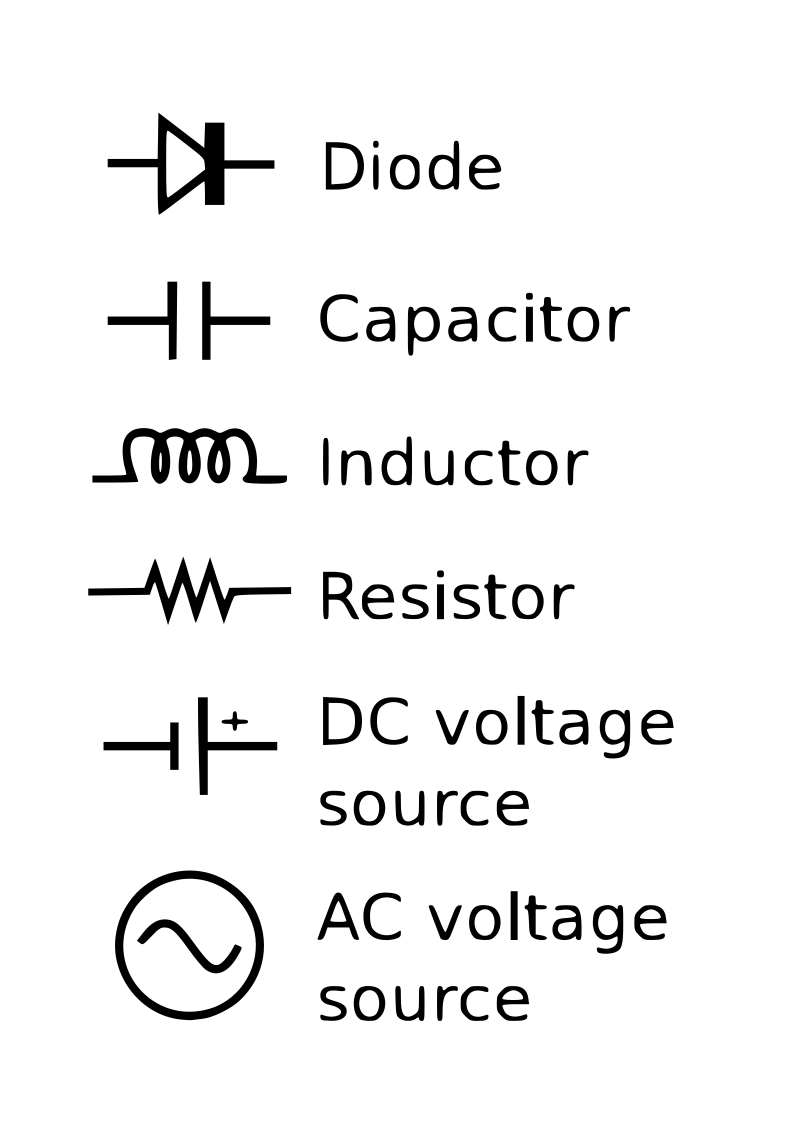
Once the board was designed and laid out we had to study what components would be needed to construct our circuit. Looking through the layout of the circuit I could see that the components were labeled.
- R labels resistors. A resistor is a component that helps to control or limit the flow of current to other components in the circuit.
- C labels capacitors. A capacitor stores energy and discharges it when needed.
- D labels diodes. A diode is a component that conducts electric current in one direction only.
- An LED, also known as a light emitting diode, does just that and uses current from the microchip to illuminate. The circuit required two LEDs, a red and a green.
- An AT Tiny 45 microcontroller and a 6 pin 2 by 3 header was also needed. These components store and transfer program data. Each of these components were also recognizable by their symbols.
With all the components determined I recorded them onto a sheet of paper. I wrote what each component was and how many of each were needed. This helped to keep me organized when it came to keeping track of all my small components. After reviewing the Fab Lab inventory I isolated each required component. I removed that number of components and taped it to the paper next to the name previously recorded.
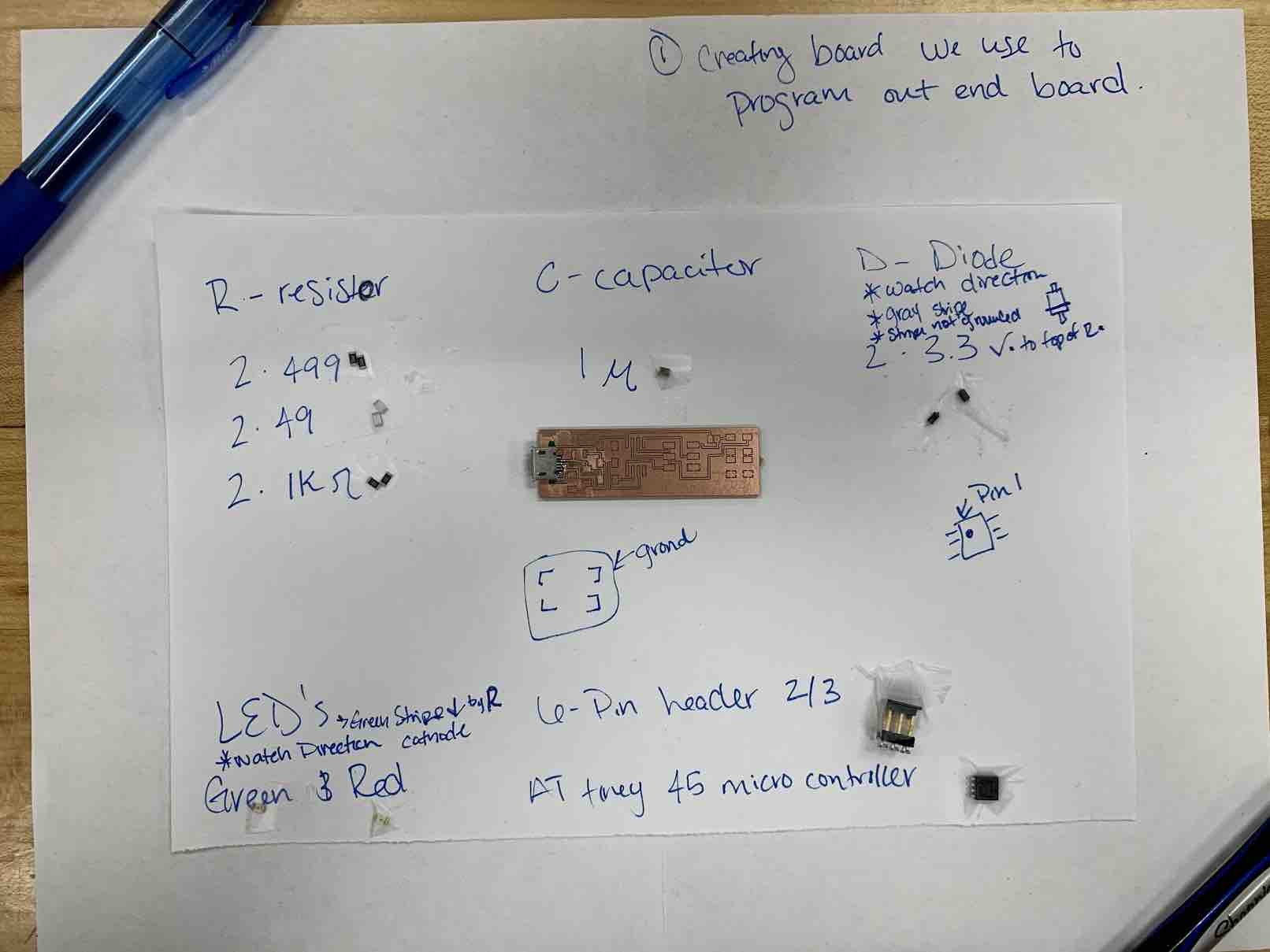
This set me up to be more organized in my soldering stage.
Learning to Small Solder
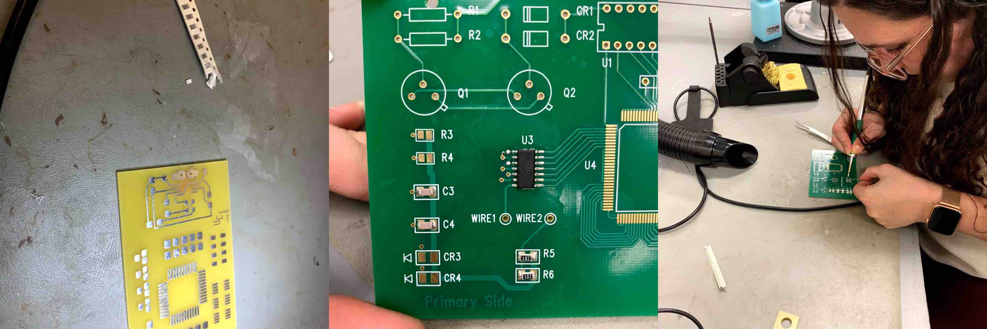
Before I started with my programmer I test soldered similar components to a scratch board. I worked with resistors and capacitors to step through the soldering process. When soldering there are many different safety concepts to keep in mind. The soldering iron itself is extremely hot and can burn things easily, such as skin or through protective wear. The soldering process emits fumes that can be harmful, therefore each soldering station is equipped with a ventilation hose to remove toxic vapors. Working with objects that haver sharp edges and points can be a puncture hazard as well.
With safety in mind I began the process of learning how to solder smaller connection. I have some experience soldering through-hole but surface mounting is quite new to me. The soldering process is documented in the next section of this page.
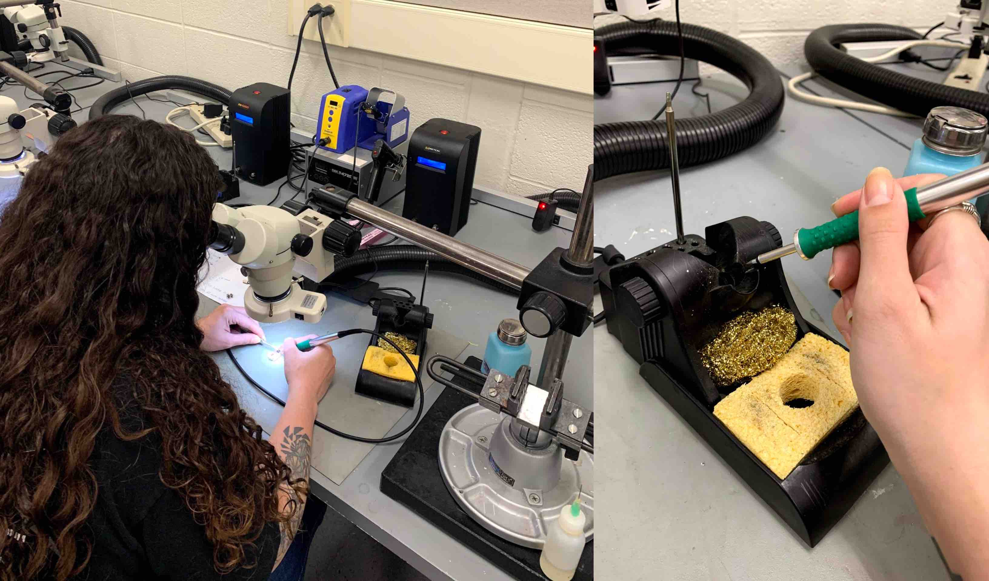
Soldering Components
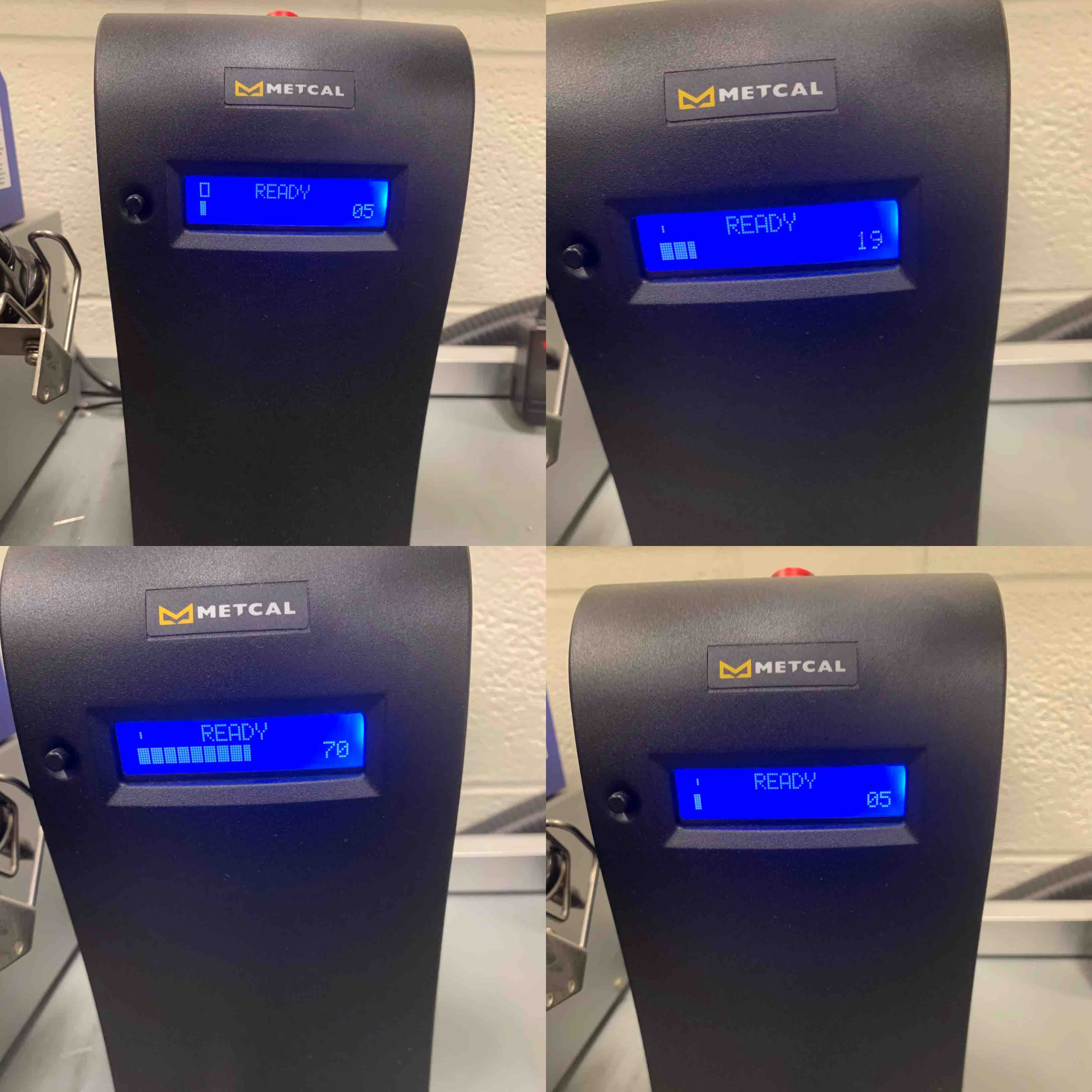
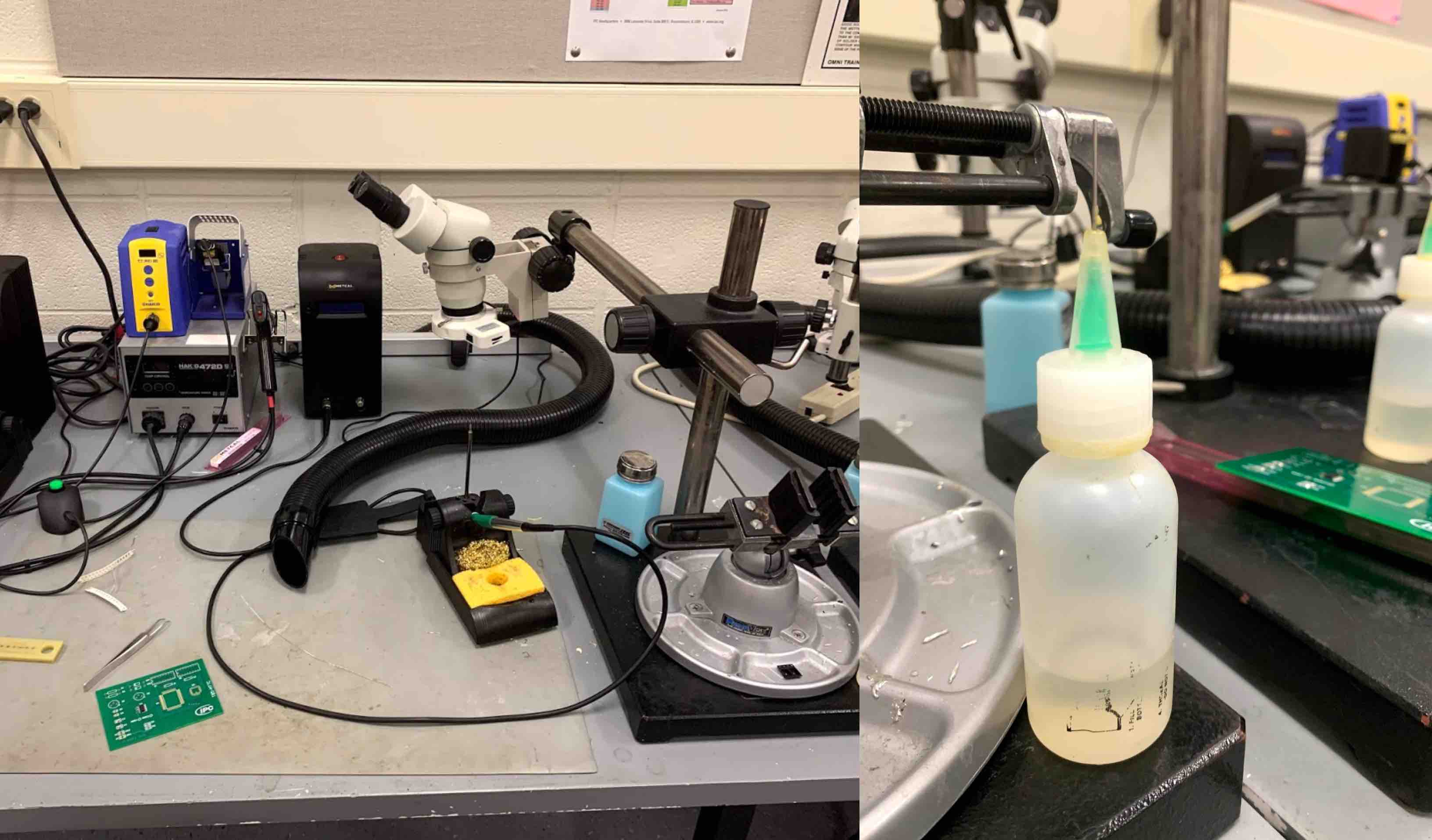
As mentioned above, when soldering keep in mind safety regulations. I began by placing my component sheet onto my workstation, laying out my board, and focusing my microscope. Setting up my work station is important for efficiency and organization. I then turn on my heating element for the soldering iron. The iron is connected to a Metcal black box with a red power button on top. Flipping the switch turns the LED screen on and it begins is heating cycle. Each time you lift the soldering iron for use you must wait 4-5 seconds for the Metcal heating element to heat up and settle back to a working level of heat. When the bars drop back down you are ready to use the soldering iron.
- The first step is to set up your work station. If you would like to use the ventilation that can be switched on at the wall and run through the hose.
- I removed the components from my prep sheet I planned to start with. I began with 2 of the resistors. I placed my programmer chip under the microscope and placed my resistor with fine point tweezers onto the board. I made sure to have it facing the correct direction.
- Once my resistor was in place I applied a drop of flux over the component.
- I pulled my soldering iron from the stand, let it heat up, and then touched it lightly to one end of my component. I left it there for a one two count and then removed it. This applied heat to the small amount of solder on the component to lightly tack it in place. This is to help keep your component from moving while in the soldering process.
- Once tacked on one side I rotated my board to solder the opposite side of the component to the board. I lifted my soldering iron, let it heat up, and then placed it to the board by the connection to the component. With a line of solder in my other hand I came in contact with the iron and component connection. This liquefied the solder. I removed the iron to leave the solder behind as it quickly went rigid. I rotated the board back to the other side of the component and soldered that side to the board. This completed my first soldered component to my programmer. I completed the same steps for the other resister I pulled from my prep sheet.
- I then soldered my AT Tiny 45 Microcontroller. This component having more connections that needed soldered, I tacked the middle prongs first and then soldered each of the eight prongs separately.
- This is important to pay close attention to. If the solder goes into the routed line and bridges to the other side it creates a connection to the ground. This could blow your circuit when attempting use.
- This is important to pay close attention to. If the solder goes into the routed line and bridges to the other side it creates a connection to the ground. This could blow your circuit when attempting use.
- I completed the solder step for each of the components on my prep sheet. I followed the circuit layout to be sure they were in the correct place.
- Two of the components used in this layout were direction oriented and had to be sure to be placed a certain way. The two diodes, and the 2 LED’s have line marking to help orient the component in the correct direction.
- Two of the components used in this layout were direction oriented and had to be sure to be placed a certain way. The two diodes, and the 2 LED’s have line marking to help orient the component in the correct direction.
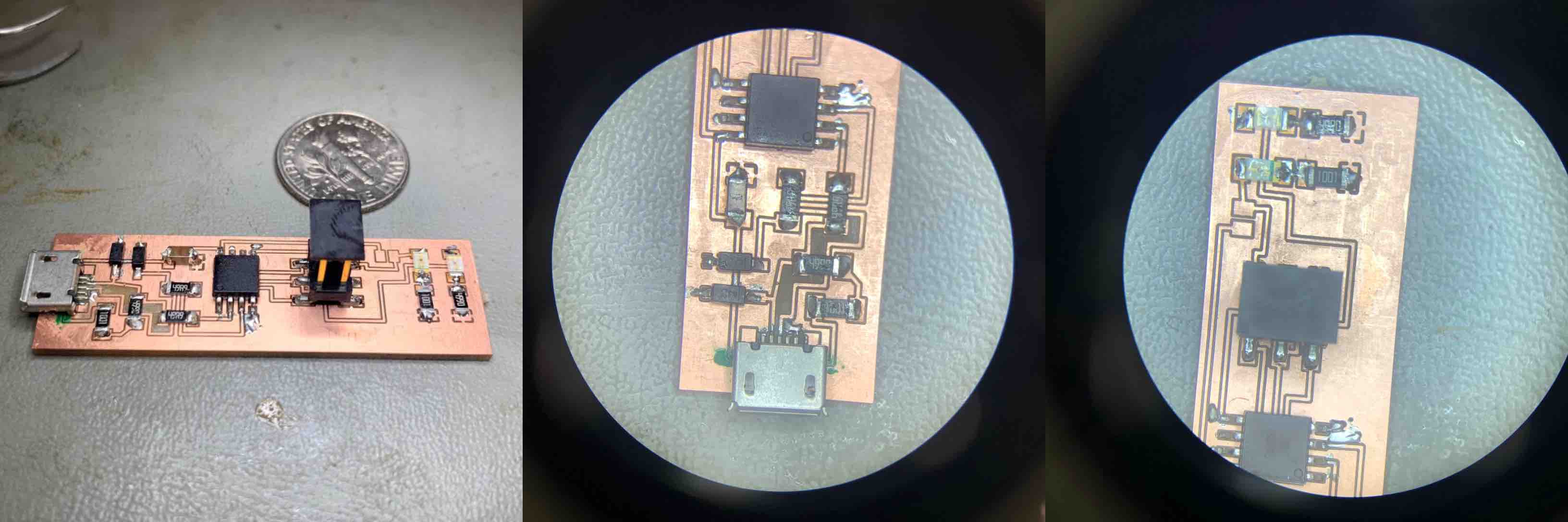
- Once all pieces were soldering in place following the circuit drawing I solidified the USB connector and was ready to program my programmer.
Component Soldering
Programming
Set Up and Connection
The source code to program the ISP is contained within the Zip folder below and can be found on the Brian Board page linked above.
With a few adjustments to the programmer I was successful in using this to upload program to a chip that controlled an LED strip that is 20 LED’s long. My original programmer that I had built and soldered did not quite function as expected. I struggled to get the board to communicate. The second board is the board I show programming.
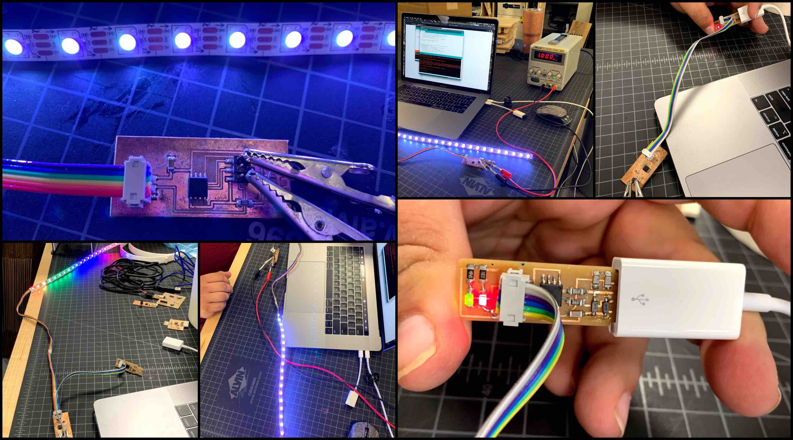
The programmer plugs directly into the white USB adapter, this adapter then plugs into the laptop directly. The usb port then reads the programmer and Arduino IDE is able to program this using the code written. The programmer is connected to chip being programmed with a rainbow connection cable. This process is uploading the ISP program to the board to make it a functioning programmer.
In order for the programmer to transfer, hold, and process data is needs to be loaded as a programmer. This must be the first step in preparing the ISP to program another board. When the ISP is programmed to function correctly it can then be loaded with the program wanting to run a certain function and connected to the board it is set to program.
Another cable then connects the chip to the LED strip. When powering the LED string the chip must be connects to a power source. In this project we used an external power source with a cable connection to both the power and the ground connections on the board.
Code and Programming
Strand Test code is provided in the Zip folder below and used in the final results.
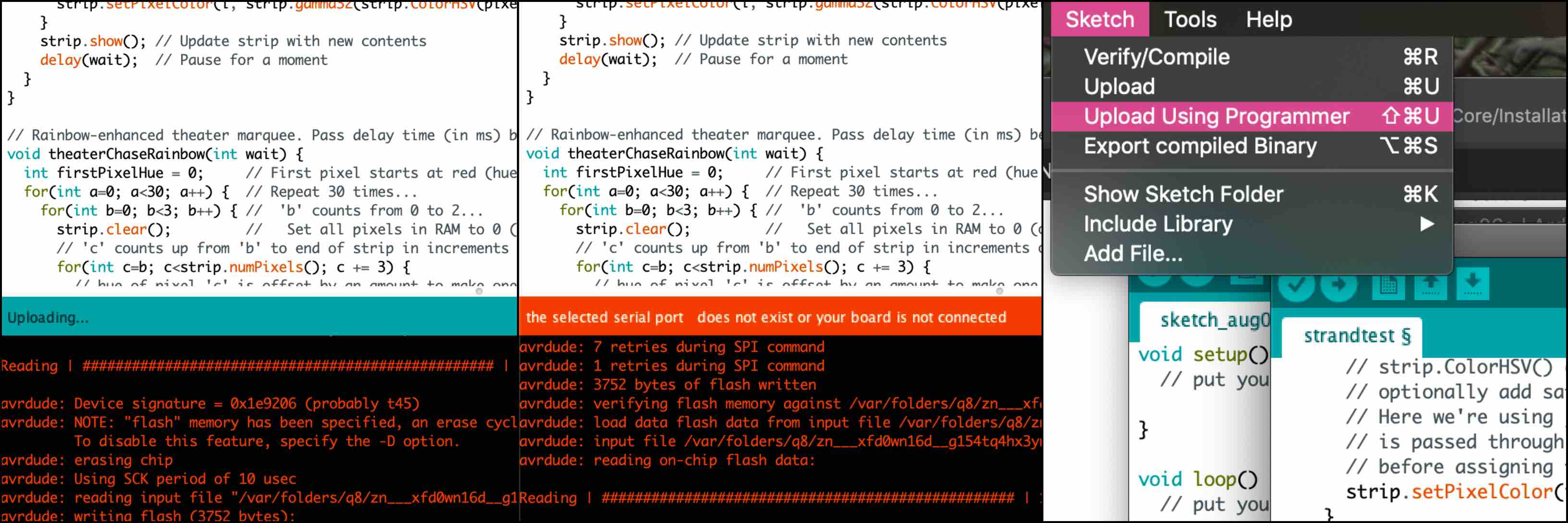
At the first attempt in uploading the code, it failed. I double checked all my connections to be sure they were transmitting and receiving correctly. Everything looked clear. The power was successfully connected, and board appeared to be working. However, Arduino could not see my board as connected. I then used the setting under Sketch to Upload Using Programmer. This was successful and the issue was resolved.
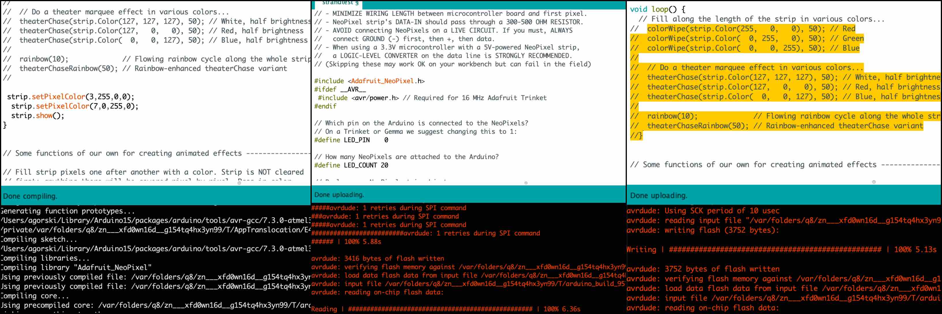
Once the compiling process was finished, showing no errors, I was able to upload my code. The uploading was successful and the LED strip preformed the rainbow led cycle. I specified in the code. This was different from the original code uploaded that was set to all LEDs HIGH to provide power and light up.
Final Results
Note: I did not use this process to program my final project. My final project was more compatible with the process of programming with an FTDI cable.