19. Final Project Development and Process
Throughout the many many weeks of project development this page will be updated with the documentation of each step.
Useful links
Weeks 1 & 2 - Project Development and Computer Aided Design
In these weeks I spent time developing and documenting my final project idea. As my sketches traveled from mind to paper, my project began taking dimensional form. I assigned accurate representation of sizes in the model and animation found below.
3D Model Animated
Week 7 - CNC Making Something Big!
With this assignment I was able to determine my overall theme and design an educational charging station. Theming my final project with Solar Education!
Developing My Theme
For these designs I wanted to match the theme of my final project being Solar Education. This was represented throughout the whole design. The engravings located in the top of the shorter table option will represent solar phases of the moon. A solar phase being defined by the Encyclopedia Britannica as the varying appearances of a celestial body as different amounts of the disk are seen (from Earth, ordinarily) to be illuminated by the Sun.
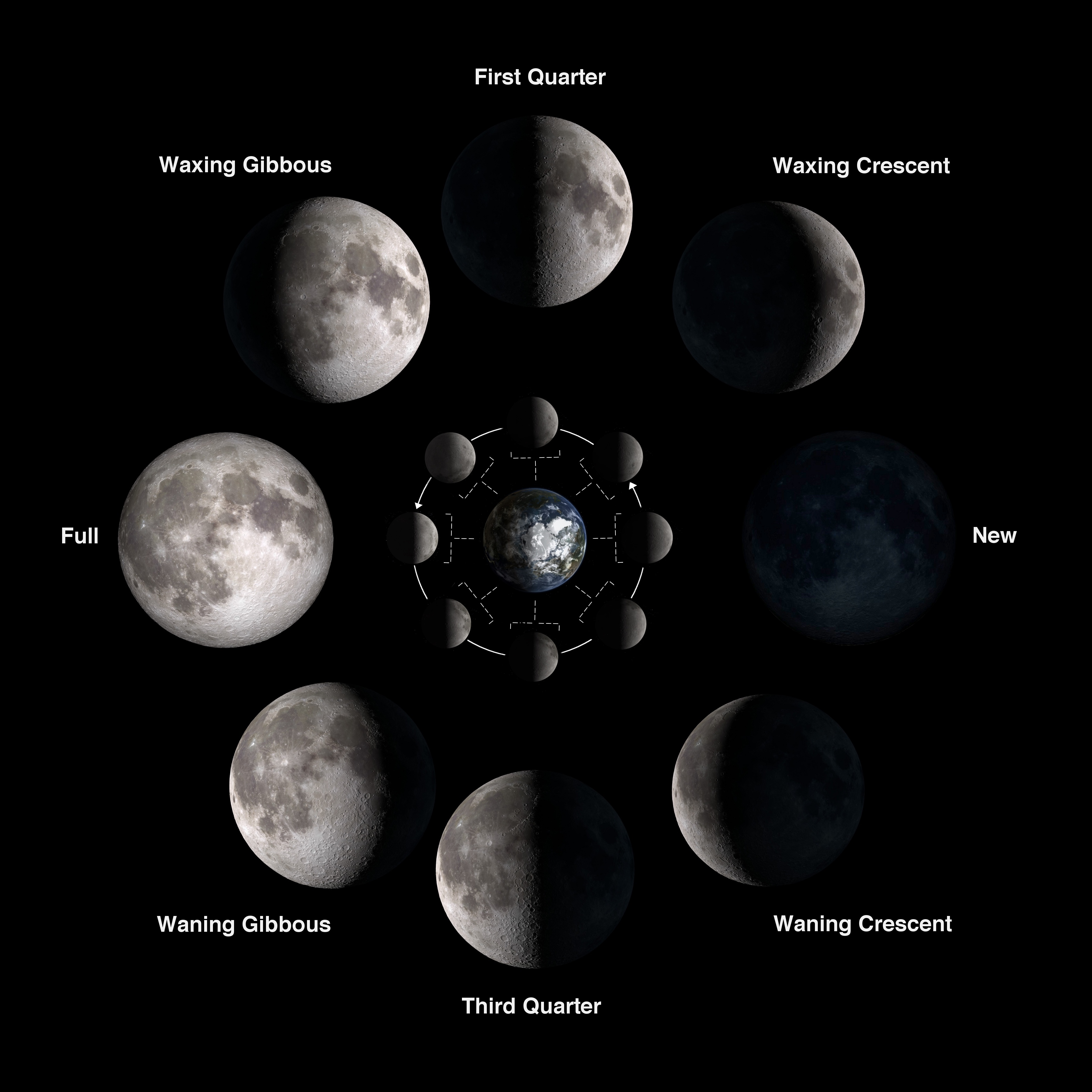
With the inspiration from the above image each moon phase will be shown in a circular pattern, leaving the middle open for the degree triangle. The Solar representation for the top of the taller design option will be left free of design for he middle to be focused on the placement of the degree triangle for optimal solar energy obtained.
The leaf representation found in both the table design and the light itself educationally represent the photosynthesis process. The process of green plants to absorb sunlight and use it to create food. The reaction of the carbon dioxide and the water create the food source that produces a byproduct of oxygen.
With these concepts included in my theme of solar education the tables can be used to teach from as well.
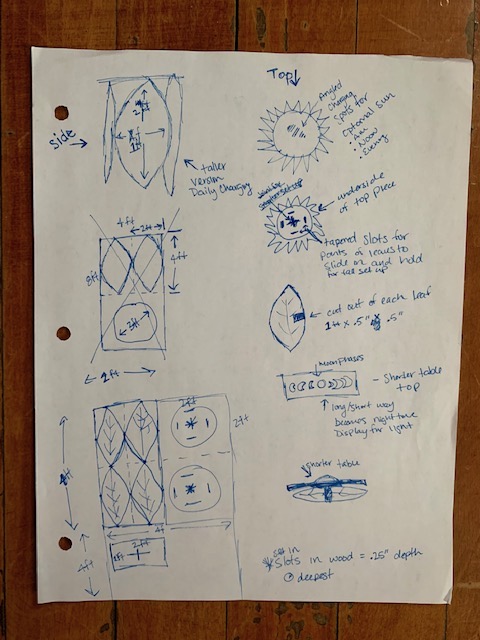
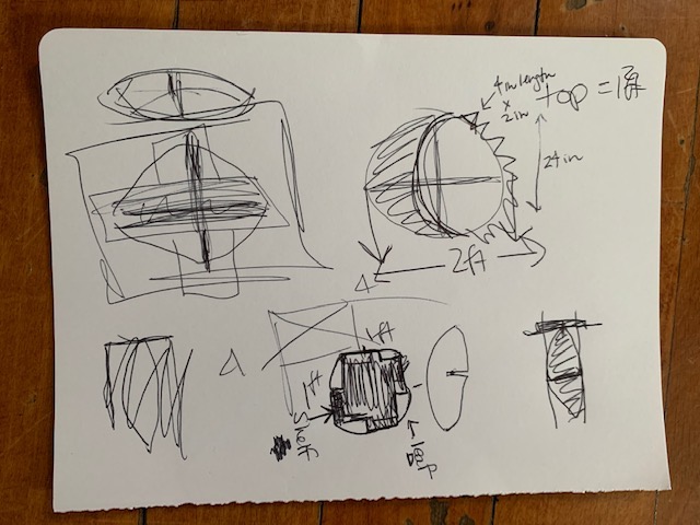
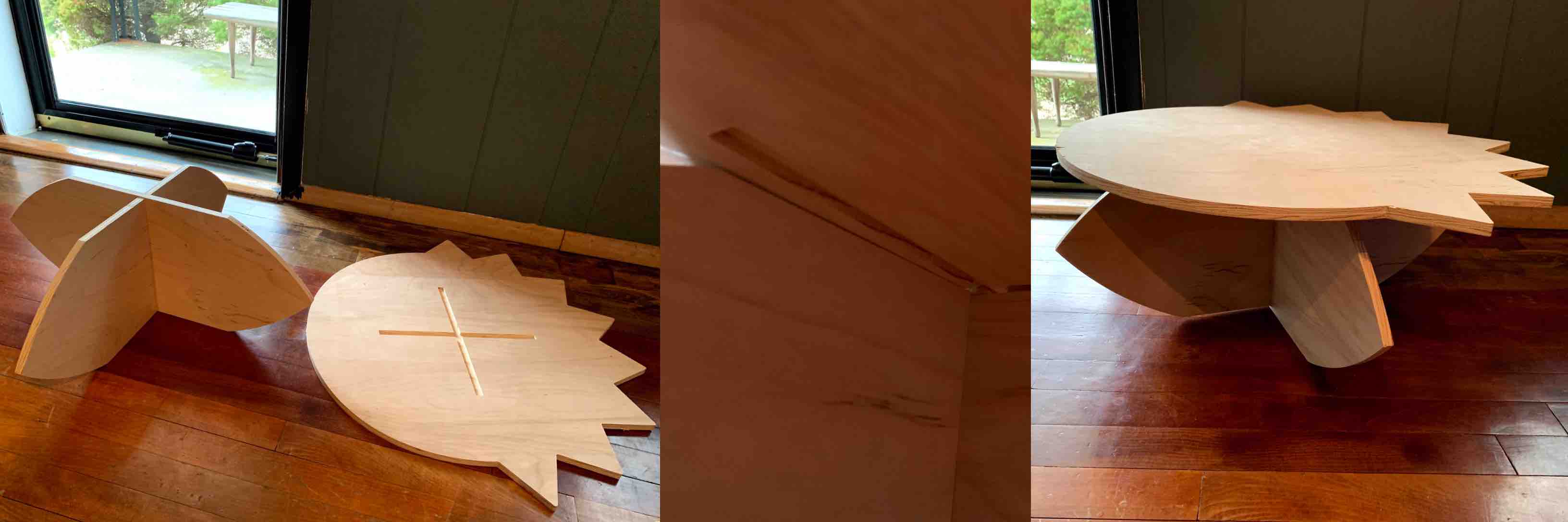
With these parameters in mind I was still struggling to conceptualize how much space I had and what sizes I should be making my pieces. I decided to switch first to good ol’ fashioned pen and paper. Being able to sketch all of my intended pieces, along with how many of each is needed. I created the leaf shape, with the suggested measurements. I then created perspective sketches to determine how many of each piece I needed. I chose four leaf shapes to serve as legs. My original dimensional suggestions were instantly too large. I took my idea and I scaled it down. This gave me room on my board to create the top and bottom of my table.
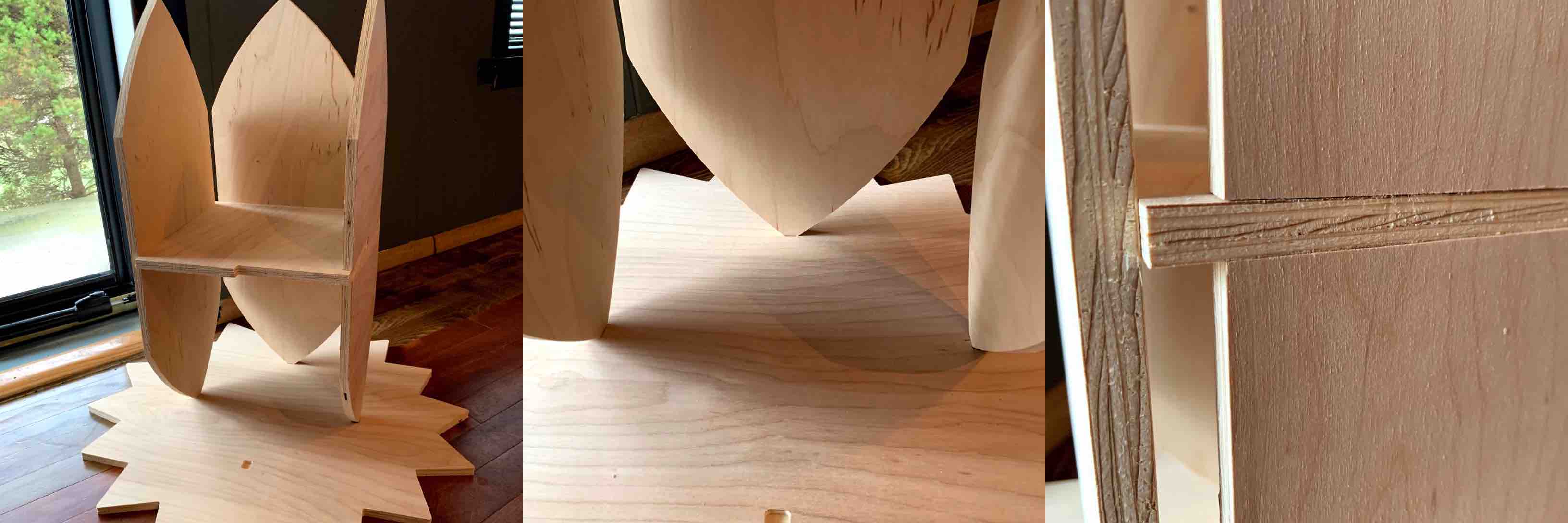
I decided to design a solar sun shape for the top. This went along with my theme. Addressing the stability issue I decided to engrave a half inch into the underside of the top in the positions where each leaf leg comes in contact with the top of the table. I decided it still needed more so I added a base, which was a replication of the top for symmetry. With more space available on my 4 foot by 8 foot sheet of plywood a thought dawned on me, this could be multipurpose! I decided to design the leaf legs to have slots removed form the edge of each into the middle. This was then stabilized further with a shelf attached through the open slots. and fit to the size available inside the table design. With the slots designed into my leaf legs the table can be disassembled. With two legs now intersecting on their sides through the slots the additional table top can be placed on top. The underside of this table top is engraved .25” for the intersection to be stabilized. This smaller table is an educational piece, to be engraved with the phases of the moon. This also sits much closer to the ground, accommodating children.
Make Something Big! … Constructed!
The construction of my something big is pretty simple. This is to ensure ease of use. It also come apart to store flat.
The first pieces that should go together is two of the leaf legs and the shelf. This starts with the stability of he structure. With these three pieces together the edges of the leafs should be places in the recess aligning with concept design.
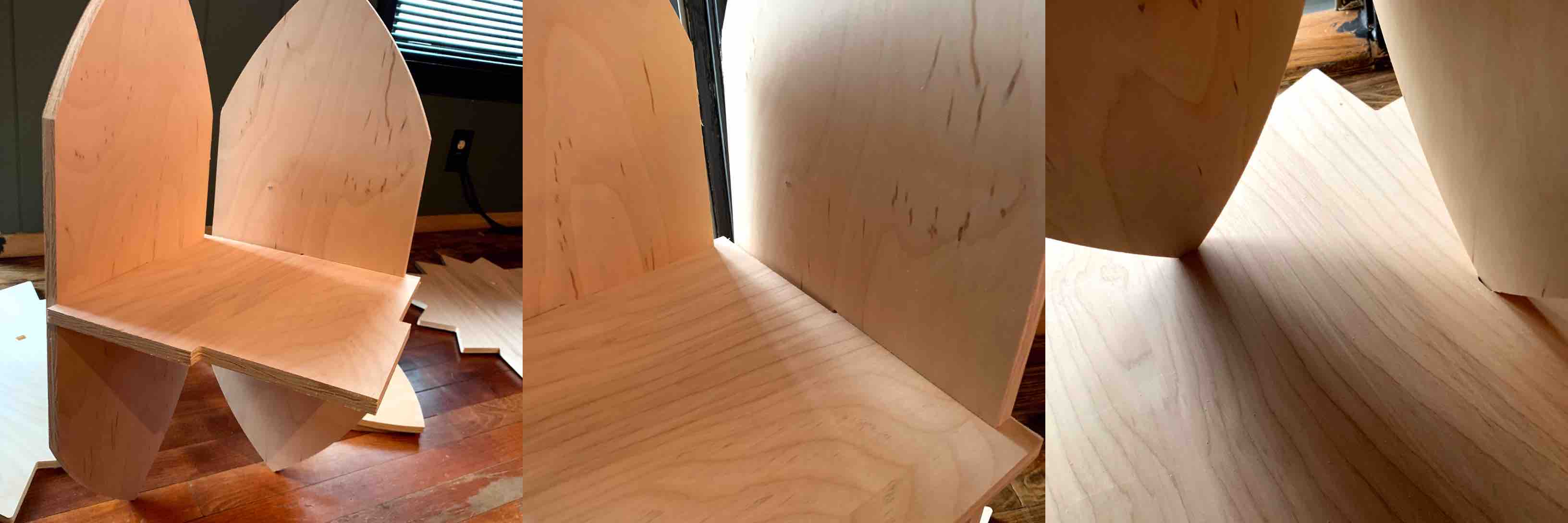
Each of the leaf legs should then be attached with the slotting and lined up in the recesses of the bottom piece.
When all 6 of these pieces are together you will already feel retaining tension and it can at this point stand freely on its own. This is when the top piece should be added.
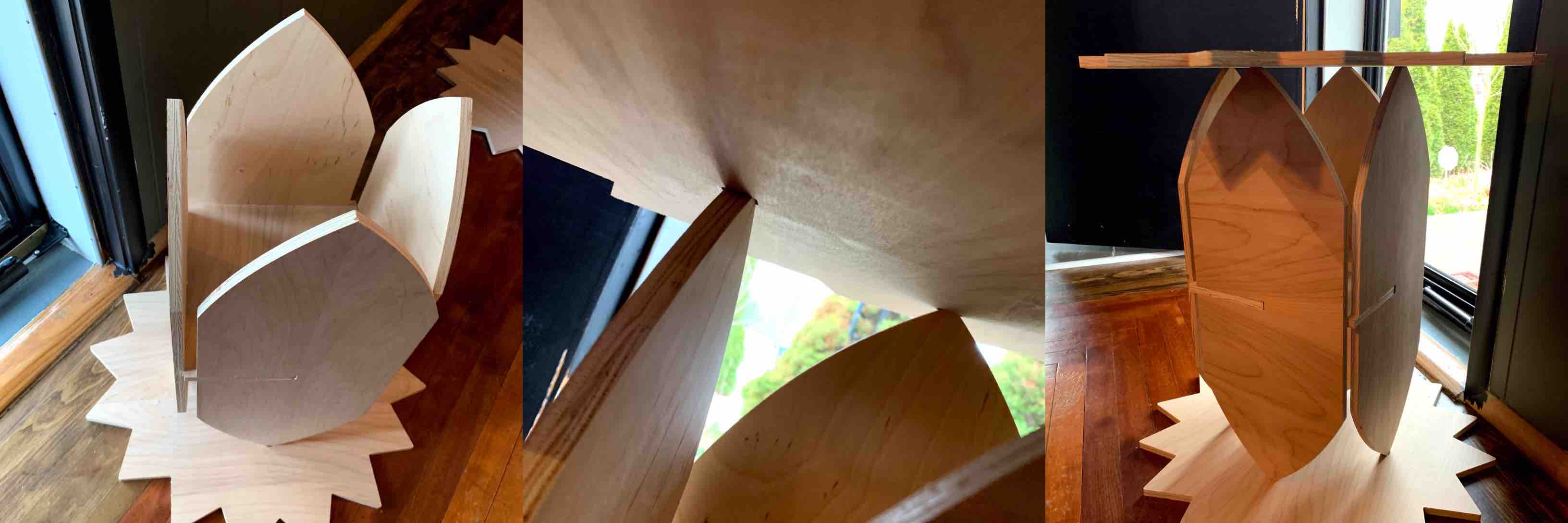
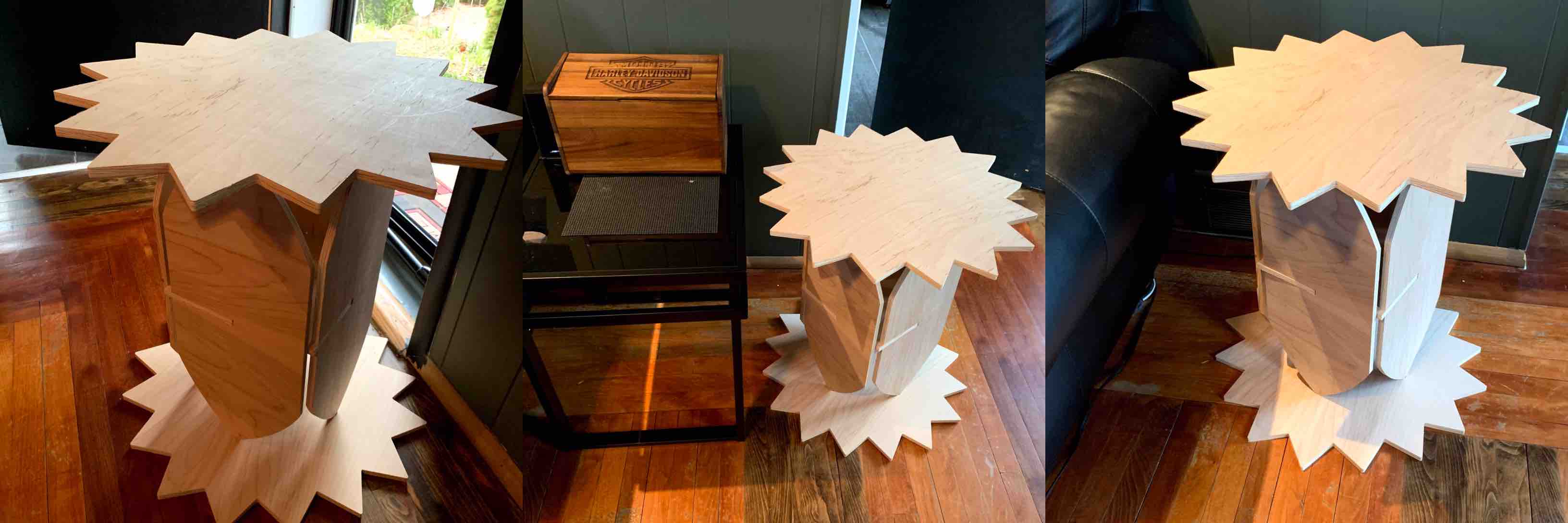
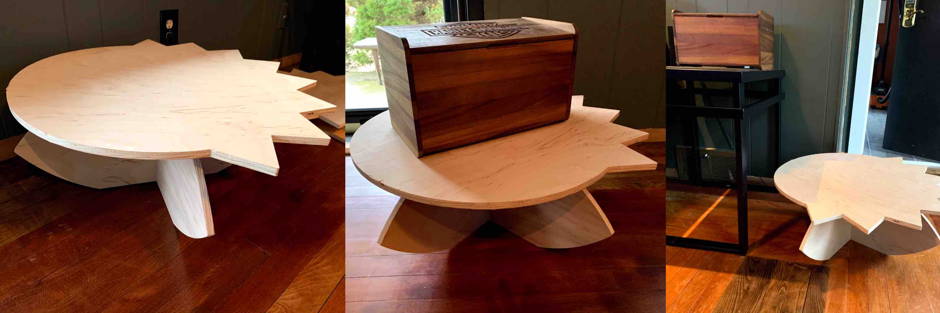
With the table top sun in place, being sure to align the top recesses as well, the tall construction of pieces is complete. This holds its structure, weight and places well next to a couch in place of an end table.
The tall table must be disassembled in order to assemble the smaller version. This was the original intention, that the table could be assembled in two different stable constructions. With two of the leaf legs and the sun/moon table top the smaller construction can be competed. Taking the leafs and using the slots previously supporting both structure and the middle table are used to intersect. This in turn creates a cross shape.
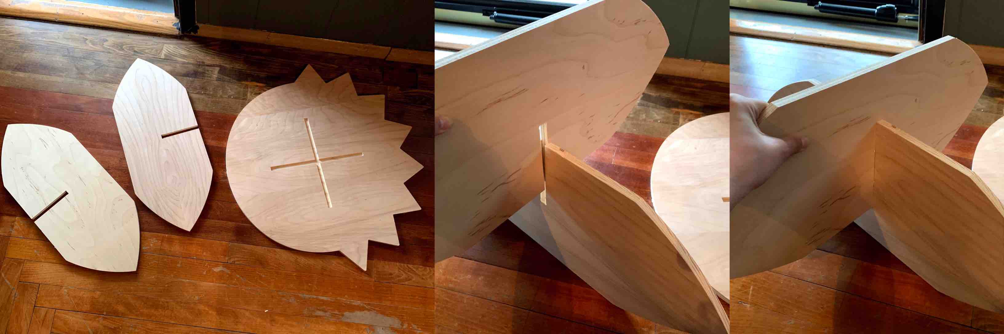
When referring to the underside of the table top there will be a recess in the same shape. This shape directly lines up with the leaf legs. When placed together the recess allows to legs to fit and create a more stable construction.
After construction the small table proved quite sturdy and durable. The table compared to half the height of the taller construction. This was the perfect height for the intended use as a child’s education work table.
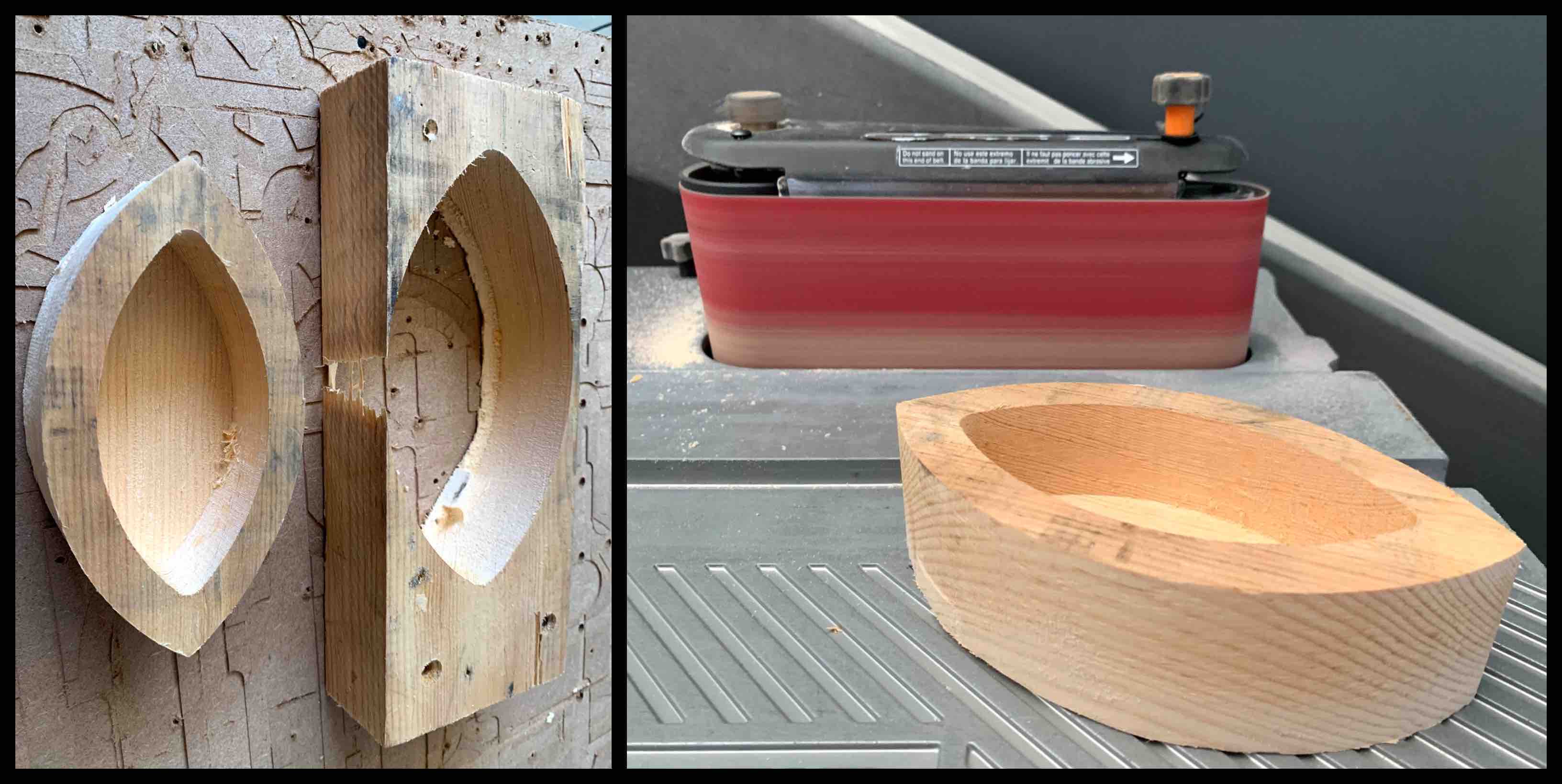
Leaf Light Body
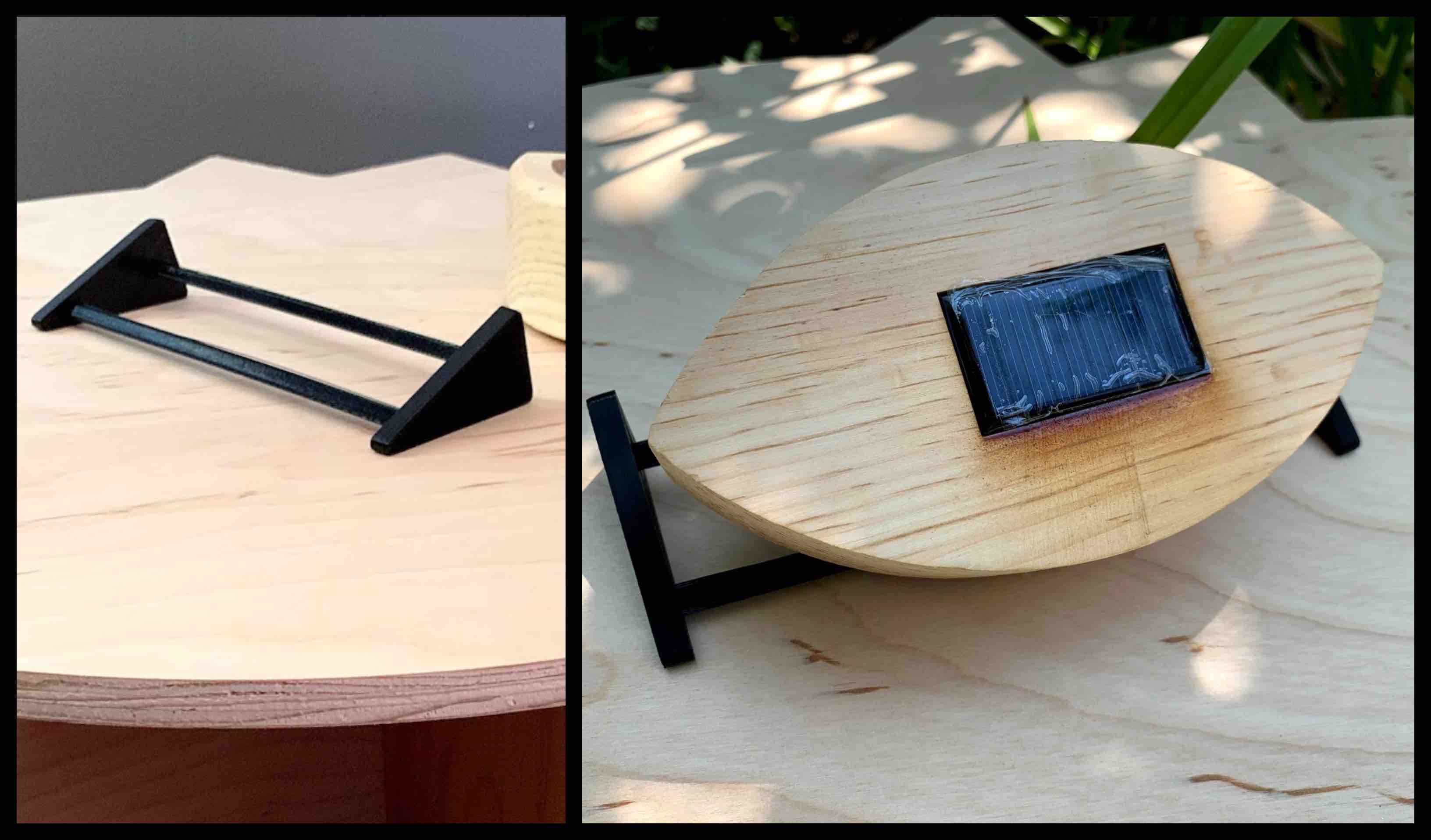
With the experience I gathered while completing the Make Something Big! week I routed the body or electronic housing for my final project. I used a half inch endmill and designed the inside to be routed as a pocket to be sure my dimensions did not change. (These same dimensions are used to mill the vacuum forming mold, so they must be consistent.) I then used a belt sander to smooth the edges and a small router to round the outside edge.
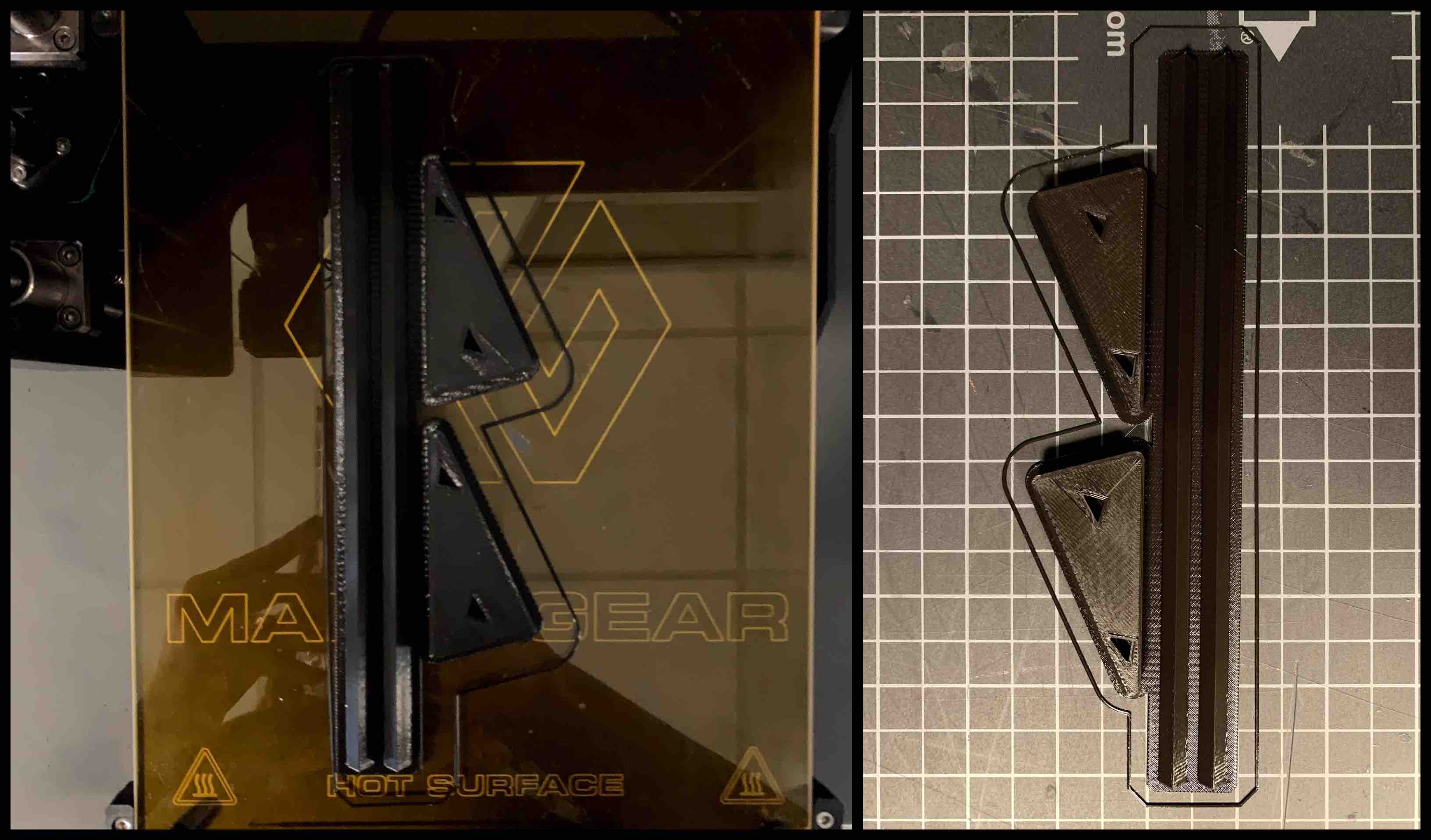
3D Printed Stand
I decided that I needed a stronger additive process so I used the Sindoh 3D printer to make a stand. The stand has built in angles that set the solar light for 60 degree angle used in the winter, 45 degree angle for spring, & 20 degree angle for summer. This will optomize the amount of light charging the solar circuit.
Week 10 - Applications and Implications
Upcycled Materials:
-
Wooden Pallets no longer being used - I am hoping to get this material donated. My local lab has mentioned having broken pallets, as well as other sources such as retail stores.
-
Old Plastic Grocery Bags - I want to get donated and upcycled from home collections.
Physical Components:
- 5V Solar Panel - $2.04
- Circuit Board - $5.95
- ESP32 Microcontroller - $10
- RGB LED - $1.05
- Resistors - $0.15
- Switch - $0.64
- Rechargeable Batteries 6v - $2.00
- Photo Cell - $0.95 or Phototransistor - $2.00
- Transistor - $0.29
Digital Components:
- Application for Phones - I plan to create this myself using the applications I have been learning and adding addition education to that. This application will interact with the Leaf Light to control the color output for the light. This should not have a cost.
Overall Part Cost = $22.78
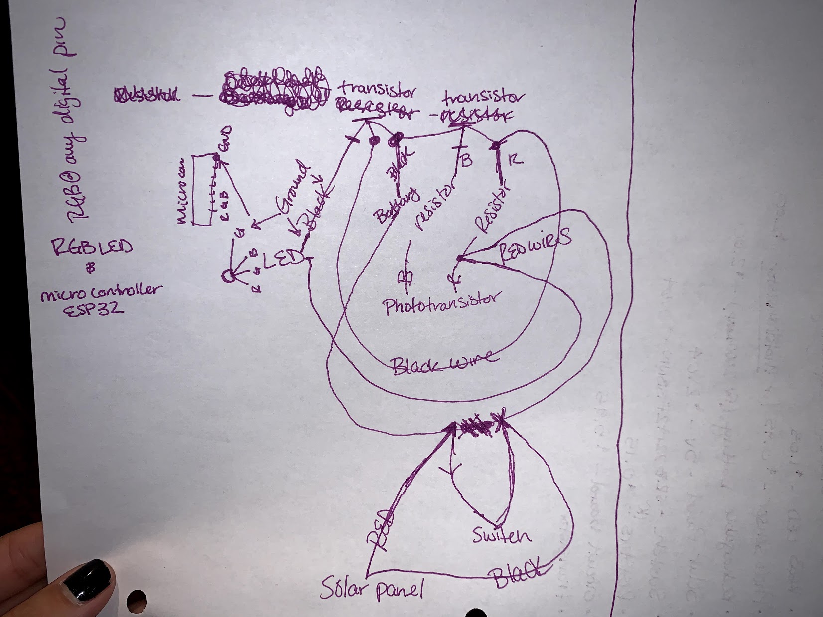
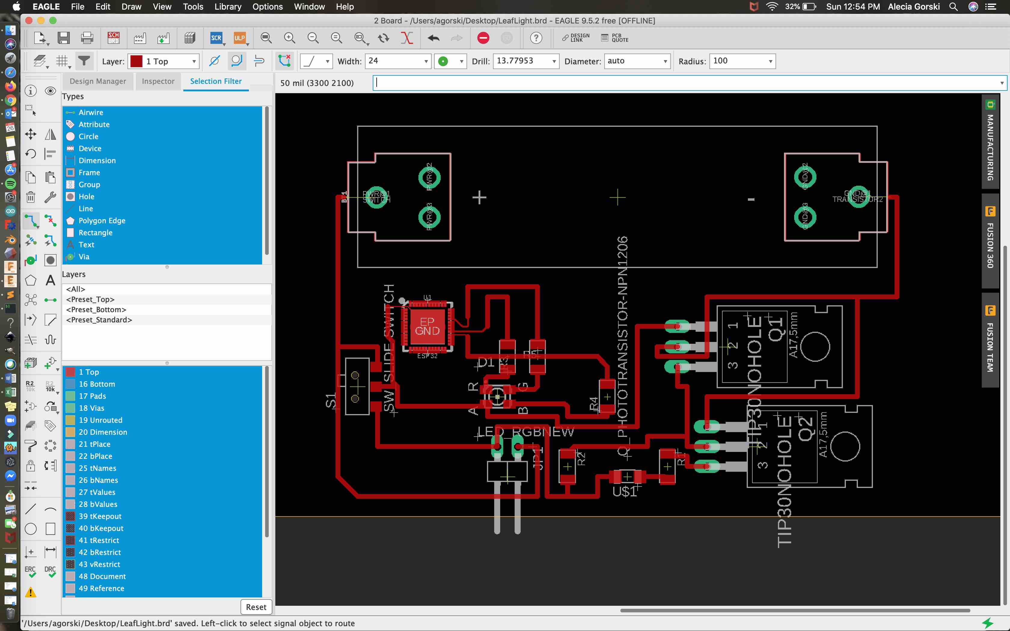
Basic Circuit Sketch and Eagle Layout
Breadboard Development with ESP32 Dev Board
Installing ESP32 (above) - It was necessary to download the ESP32 board to the Arduino interface. To select that the program communicates with the correct board the installation process must be completed.
USB Prober (above) - To allow my USB connection to be seen through Arduino. My port was not being seen so I had to install the USB prober. It was suggested that there is not enough power to run the connection.
Silicon Labs (above) - Legacy OS Software and Driver Packages for the USB port
Circuit Complications
I decided for my final project I wanted to work with an RGB LED. I adjusted my circuit to represent the RGB LED. This entailed reworking my circuit for the correct pins. I had to determine which of the pins on my ESP32 Dev board would connect and control each of the colors on the RGB LED.
My first complication came from uploading script to microcontroller and it functioning successfully. As explained in week 13 I had to download the Blynk Library, install it, and pull up the WiFi Scan to be sure it was connecting. The USB connection to the microcontroller Dev board was not showing and I had to follow the trouble shooting options shown below to help boot the board.
Once I was able to successfully connect the microcontroller to the WiFi my next complication was connecting my phone application to microcontroller. With the WiFi connection code in the Arduino work space I was able to compile and upload the correct code. This code required my WiFi ssid, WiFi password, as well as the specific authentication code per Blynk project.
With the correct code I was able to connect to my device. I then followed the same steps outlined in week 13 to create 3 buttons, label them with color, and connect them each the the pin representations on my ESP32 Dev board. When the correct connection and pins were selected for each button I used the play button to enter the communication mode. When pressing the button for each color on the phone application I was able to turn them on and off. If more than one color was on it would mix the values.
Changing Colors
Code Used
This is the code used to connect my phone to the Blynk app with WiFi.
/*************************************************************
  Download latest Blynk library here:
    https://github.com/blynkkk/blynk-library/releases/latest

  Blynk is a platform with iOS and Android apps to control
  Arduino, Raspberry Pi and the likes over the Internet.
  You can easily build graphic interfaces for all your
  projects by simply dragging and dropping widgets.

    Downloads, docs, tutorials: http://www.blynk.cc
    Sketch generator:           http://examples.blynk.cc
    Blynk community:            http://community.blynk.cc
    Follow us:                  http://www.fb.com/blynkapp
                                http://twitter.com/blynk_app

  Blynk library is licensed under MIT license
  This example code is in public domain.

 *************************************************************
  This example runs directly on ESP32 chip.

  Note: This requires ESP32 support package:
    https://github.com/espressif/arduino-esp32

  Please be sure to select the right ESP32 module
  in the Tools -> Board menu!

  Change WiFi ssid, pass, and Blynk auth token to run :)
  Feel free to apply it to any other example. It's simple!
 *************************************************************/

/* Comment this out to disable prints and save space */
#define BLYNK_PRINT Serial


#include <WiFi.h>
#include <WiFiClient.h>
#include <BlynkSimpleEsp32.h>

// You should get Auth Token in the Blynk App.
// Go to the Project Settings (nut icon).
char auth[] = "Your Authentication Code";

// Your WiFi credentials.
// Set password to "" for open networks.
char ssid[] = "WiFi Name";
char pass[] = "WiFi Password";

void setup()
{
  // Debug console
  Serial.begin(9600);

  Blynk.begin(auth, ssid, pass);
}

void loop()
{
  Blynk.run();
}
This code was adapted and combined with another in attempt to adjust RGB LED by each color. This code combination compiled well and uploaded but instead of changing the colors it cycled through each of the colors with no control over the change.
int photoTran = 27;
int reading = 0;
int LEDpin3V3 = 2;
int LEDpinR = 26;
int LEDpinG = 25;
int LEDpinB = 32;

/* Comment this out to disable prints and save space */
#define BLYNK_DEBUG // optional
#define BLYNK_PRINT Serial

#include <WiFi.h>
#include <WiFiClient.h>
#include <BlynkSimpleEsp32.h>

// You should get Auth Token in the Blynk App.
// Go to the Project Settings (nut icon).
char auth[] = "Authentication Token";

// Your WiFi credentials.
// Set password to "" for open networks.
char ssid[] = "WiFi Name";
char pass[] = "WiFi Password";

void setup(){
pinMode(photoTran,INPUT);
Serial.begin(9600);

pinMode(2, OUTPUT); //sets the digital pin 2 as output
pinMode(26, OUTPUT); //sets the digital pin 26 as output
pinMode(25, OUTPUT); //sets the digital pin 25 as output
pinMode(32, OUTPUT); //sets the digital pin 32 as output


// Debug console
Serial.begin(9600);
Blynk.begin(auth, ssid, pass);
}

void loop() {
reading = analogRead(photoTran);
Serial.println(reading);
delay(100);

if (reading > 3800) {
  digitalWrite(LEDpin3V3, LOW);
  digitalWrite(LEDpinR, LOW);
  digitalWrite(LEDpinG, LOW);
  digitalWrite(LEDpinB, LOW);}
  //LED should be off durring the day

else if (reading <= 3600) {
  digitalWrite(LEDpin3V3, HIGH);
  digitalWrite(LEDpinR, HIGH);
  digitalWrite(LEDpinG, HIGH);
  digitalWrite(LEDpinB, HIGH);}
  //LED should be off durring the day

else {
  Blynk.run();
}
 }
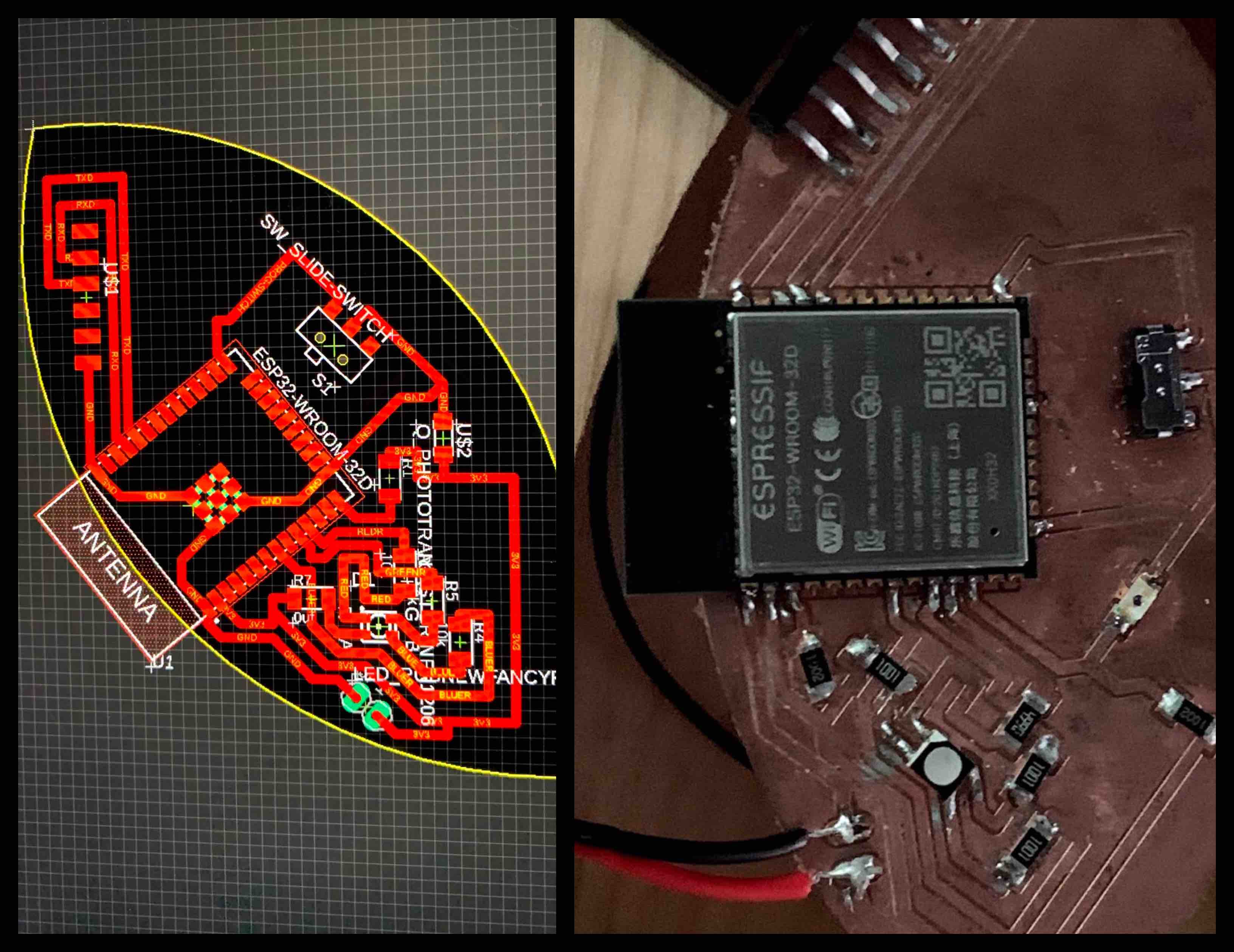
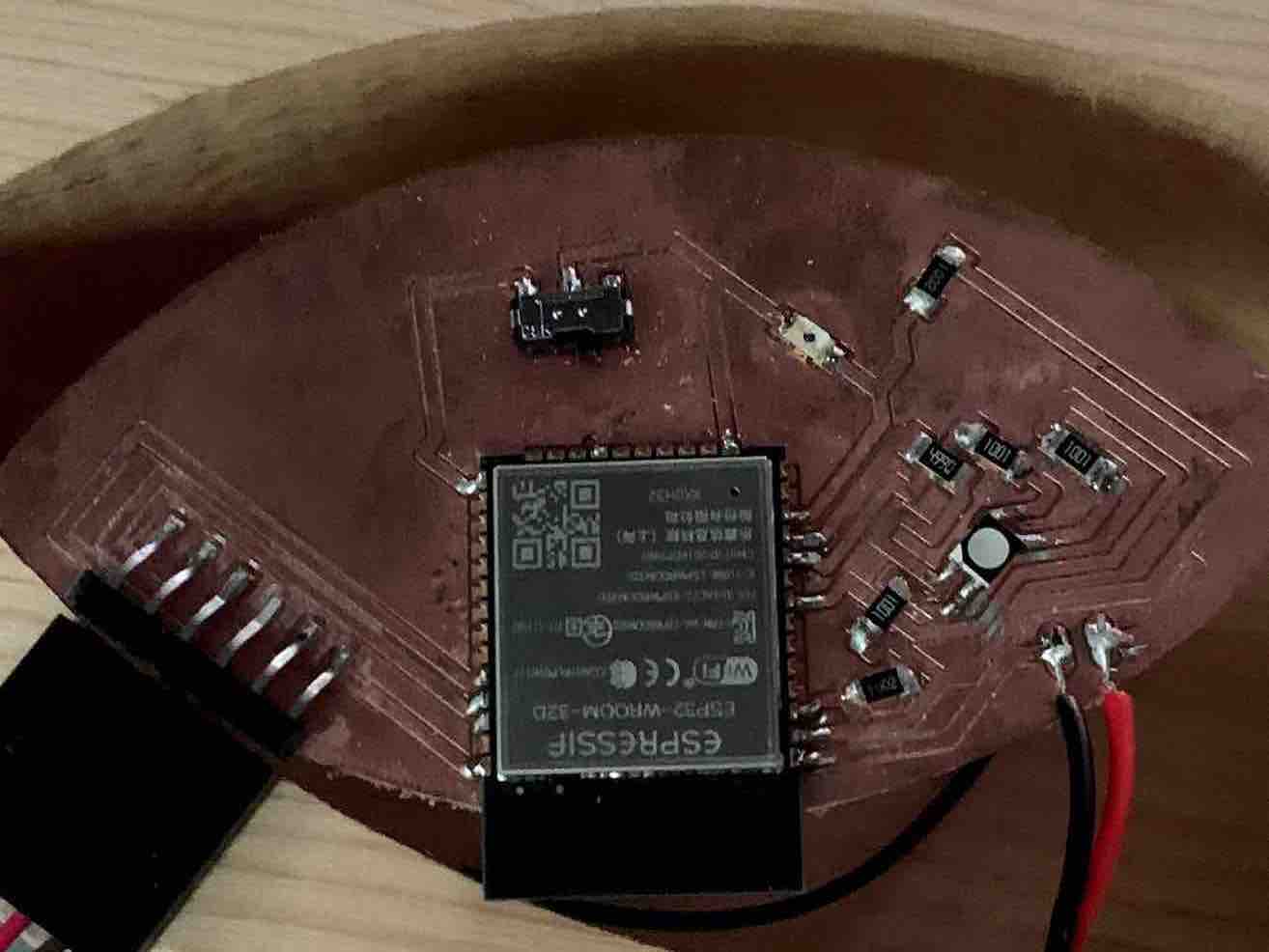
Board Development and Programming
My Board and Changing Colors
My board was cut and soldered to be used with the ESP32 WiFi capabilities. Using the WiFi connection I am able to change the colors of the RGB LED with the application interface.
Input Readings - Phototransistor
The board I built included a phototransistor to gather light readings. I used the phototransistor that reads visible light. This is then programed to control the output.
Output Devices - RGB LED
The output device is an RGB LED that I also built into the circuit. This was designed to react to the input of the readings for the phototransistor. As more light came into the phototransistor the RGB LED turns off. When less light readings come into the phototransistor the light turns on. This triggers the light to glow at night and charge during the day.
Example Recording
Final Original Board
Final Coding for Phototransistor to RGB LEG
// Written by Alecia Gorski

//uses a phototransistor reading and transmits to the esp32, this then turns the led on or off
//based on the readings received from the phototransistor

//Fab Academy 2020 (July)


int photoTran = 27;
int reading = 0;
int LEDpin3V3 = 2;
int LEDpinR = 26;
int LEDpinG = 25;
int LEDpinB = 32;

void setup(){
pinMode(photoTran,INPUT);
Serial.begin(9600);
pinMode(2, OUTPUT); //sets the digital pin 2 as output
pinMode(26, OUTPUT); //sets the digital pin 26 as output
pinMode(25, OUTPUT); //sets the digital pin 25 as output
pinMode(32, OUTPUT); //sets the digital pin 32 as output
}

void loop() {
reading = analogRead(photoTran);
Serial.println(reading);
delay(100);

if (reading > 3800) {
  digitalWrite(LEDpin3V3, LOW);
  digitalWrite(LEDpinR, LOW);
  digitalWrite(LEDpinG, LOW);
  digitalWrite(LEDpinB, LOW);
  //LED should be off during the day
}

else if (reading < 3800) {
  digitalWrite(LEDpin3V3, HIGH);
  digitalWrite(LEDpinR, HIGH);
  digitalWrite(LEDpinG, HIGH);
  digitalWrite(LEDpinB, HIGH);
  //LED should be on during the night
}
 }
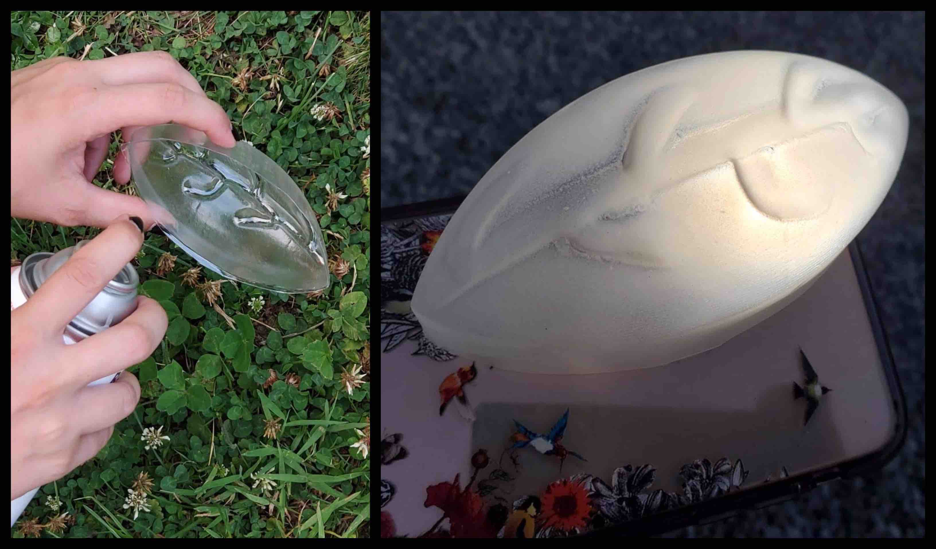
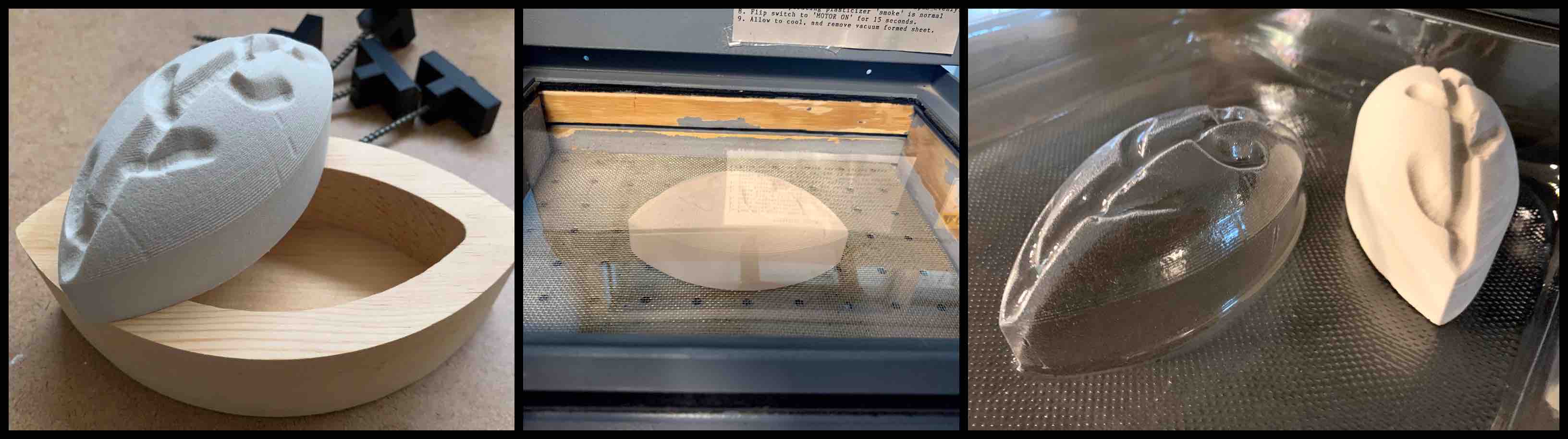
Wild Card Week - Vacuum Forming
For Wild Card week I decided to try vacuum forming. I wanted to create a soft light filter for the top of the light. This would defuse the light and allow for the it to emit softer and into a more broad space.
To do this I created the mold with the CNC Machine and REN Board. I used roughing and finishing passes to create the smooth dome shape. I also added indented areas to depict the leaf veins.
Once my piece was milled I was able to use the vacuum former to mold the PETG plastic (more information can be found in the wild card link below).
-Molding and Casting (No longer being used)-
In Molding and Casting of week 16 I designed the mold for my cast. With my cast I wanted to make the soft light filter by using the vacuum former. However this did not work and I switched my process. I milled a new piece out of REN board to then use with the vacuum former.
Final Project Review
What tasks are completed and still remain?
My final project main goal was to create the light and program it to react withing a set phototransistor threshold. I was able to accomplish this. I wanted the light to have a stable body but a cover that the light produced by the LED would be able to shine through. This was also accomplished.
What remains in my process is to design the functional solar circuit. This has proved to be a bit of a challenge. Steps have been taken to attempt this. The charge threshold became too low and fried the ESP32. This is going to mean more research and testing.
If there was time I would like to have had the chance to engrave the moon phases into the top of the table. This was intended to be used when the light was on to drive away the darkness in a child’s room they can learn about the natural cycles of the earth and how the moon effects environmental patterns.
What worked, and what didn’t?
All of my main concepts worked well. I am very pleased and very proud with the final product. I did work with a few different application programs that didn’t quite communicate the way that I was hoping. This was just an added feature I would have liked to iron out.
What questions still need to be resolved?
All remaining questions pertain to the last challenge of completing the charging solar circuit.
I would like to resolve the question of can we continue working with the web sites we have created. I would like to keep up with the skills I have learned and contacts I have made.
What did I learn?
One of the concepts I have learned well from Fab Academy is that its not always about being able to rush and force everything onto one project, its about completing the priority functions and striving for the rest.
I learned the true necessity of building on previous knowledge. Having taken this course during the COVID-19 pandemic I believe this has challenged myself and the whole fab academy community. Working on the class early on from home created a barrier in attaining compounding knowledge. This experience has proven that anything can be taught to anyone at any distance. Technology is versatile.
Final Project Summary
Evaluated Project Plan:
Over the course of the class my plan was to build part of my project each week. I decided day one of the class to use spiral development to my advantage. As I was learning the skills and the concepts of each assignment I found a way they could apply to the overall build I had in mind. Each week listed above has a concept or skill applied to the final project.
Mid way through the project development I noticed I was able to not only complete the assignments, but I was more passionate about wanting to learn the information. Choosing a project I was passionate to see completed and combining it with the spiral development working concept I was able to stay focused and alleviate any complications with the final project as they were happening.
This process worked really well for me though the course of this class. I started Fab Academy with a few projects in mind. By choosing one and working with that specifically I was able to stay on task. I am very happy with the Leaf Light and the way each process built around the concept of combining Fab Academy Technology with education, creativity, and supporting environmental sustainability.
Time Management Techniques:
I used a combination of time management and organizational skills to complete my final project.
Color Coding
- Color coding tasks can be very helpful. In my personal agenda I assign a different color to each area. For example, pink is for personal events, blue is for Fab Academy, and red is for bills. I used this same concept to prioritize my fab academy weekly tasks. Red was for overdue tasks from previous weeks, blue was the priority task that would need to be learned, and pink was the tasks I felt the most comfortable with. As they are completed they are marked off. Any remaining tasks turn red and are documented with the next weeks organizations.
Prioritize Necessary Functions
- As mentioned within each of these tasks is prioritizing. I learned with Fab Academy that the possibilities are endless and any project idea has a tenancy to grow in desired functionality. Being sure to keep committed to core functions is important. Once there is time remaining after all your organizational and time management skills pay off, working in next priority features will insure that the project works and can then be built up.
Blocking Out Specific Work Time
- Blocking out specific Fab Academy time at a set location helped to keep me focused and determined.
To-Do Lists
- To-Do lists help me to prioritize not only the weekly tasks at hand, but how they are applied to the project process overall. I make small lists the cover just one assignment, as well as lists that contain all remaining tasks that have not been completed. This can get a bit messy but with color coding and combined with the binder these organizational skills set me up for success.
Binder
- A binder helps to keep all the necessary information locked into a place or pattern. With a binder I was able to organize each week by date, tasks required, and even created a summary page that listed all tasks cumulated from previous weeks that still needed worked on. This is where I used my To-Do list.
Website Documentation Updating
- Systematic and scheduled updates to my web site were also very helpful in the success of my final project. Creating, building, coding, and presenting the project is not the only challenge. Continuous and thorough documentation is important to not only show what went into the creation but also to assist in any further advancements to the project in the future. Documentation can be a challenge to keep up on. To stay on top of the process I made sure to take pictures, videos, and other notes as I worked. I then assigned myself with a deadline within a few days of the manual work to have my basic documentation outlined in my text editor. I was sure to push as each weeks work was completed so that the newest version was always available. I tracked my documentation in my binder as well to be sure I knew which weeks I had or had not completed. These deadlines also helped to keep me on track with each week. With the built in spiral development combined with consistent website documentation updates I was pushed to stay on task and continually build my final project.
Project Essence:
How It All Comes Together
The Leaf Light overall was built to encompass the core fundamentals of clean energy combined with education. The light itself resembles a leaf found in nature, and can lead inquisitors to a conversation on how clean energy functions. The 3D printed stand is created to angle the solar light so that it gains the most amount of energy. The display stand is able to stand as a charging surface under a window or be constructed into a small table for a kids room. The table is intended to have the moon phases engraved into the top to teach children about the natural cycles of the earth. Listed below are the concepts directly relating to the final project that can be found in each week.
- Principles, Practices, and Project Management - Sketching and Planning
- Computer Aided Design - Digitally designed and formed my projects look, shape, and part compatibility
- Computer Controlled Machining - Leaf Light base as well as the display/charging table as well as the body of the light
- Input Devices - Phototransistor threshold
- Applications and Implications - Concept Growth and Breakdown
- Output Devices - LED control
- Interface and Application Programming - Blynk interaction with LED color changing
- WildCard Week - Vacuum Formed soft light filter
- Final Project Development and Process - Full Breakdown and Final Review