8. Embedded Programming
This week the assignment was to work on programming a board that you designed in as many different languages as you can. I have never programmed before, programming being one of the reasons I wanted to take this class. I learned two new programming languages in the process. I focused on working with the mcu I chose and the board I designed for my final project. I have an led built in so I wanted to show being able to program this light in more than one language.
I chose the esp32. I read the data sheet for the esp32 before working on my connections and design. This helped me to better understand the functions and capabilities of the esp32. I used the relevant information listed below:
- The pin reference to where each are located on the mcu.
- The pin descriptions were used to interpret the functionality of each pin.
- The datasheet also provided me with the information needed to determine why certain complications in my board were not working correctly. I was using a pin that must always be in low to complete a function, which required it to be high. This then would not work properly. Once I relocated the pin position the board worked correctly.
- The datasheet provided me with the information I needed to know the recommended voltage and accommodate this requirement.
- Overall reviewing the datasheet familiarized myself with the mcu I was choosing to use and better design my project from the beginning.
The datasheet can be found and downloaded from the files at the bottom of this page.
Useful links
- Group Site
- Picocom
- Quick Reference for the ESP32
- Getting Started with Python and ESP32
- Python Module Index
- Neil’s Fab Academy Video
- esptool.py install
- Remote Shell for MicroPython
- Python
- MicroPython
- Arduino
Arduino Language
The first programming language I learned was Arduino. I was influenced to learn Arduino over other languages based on my small experience with Arduino coding at an educational conference. I found it to be easy to both understand and interact with. This will be the program I work with throughout the class.
IDE
Arduino has an IDE and comes with a built in debugger. The IDE stands for the Integrated Development Environment and is a software used by programmers to develop and write code. This IDE communicates with all the development boards made by Arduino, as well as development boards made in private or student environments. This can be done by adding additional board packages. The debugger allows the programmer to check the code for issues in the writing of the code. Examples of this can be syntax errors, line spacing or indent errors, as well as certain aspects of the code not communicating clearly. This debugger will highlight the error and list the line number so that it can be addressed before being uploaded to the chip. This is also called “Compiling”.
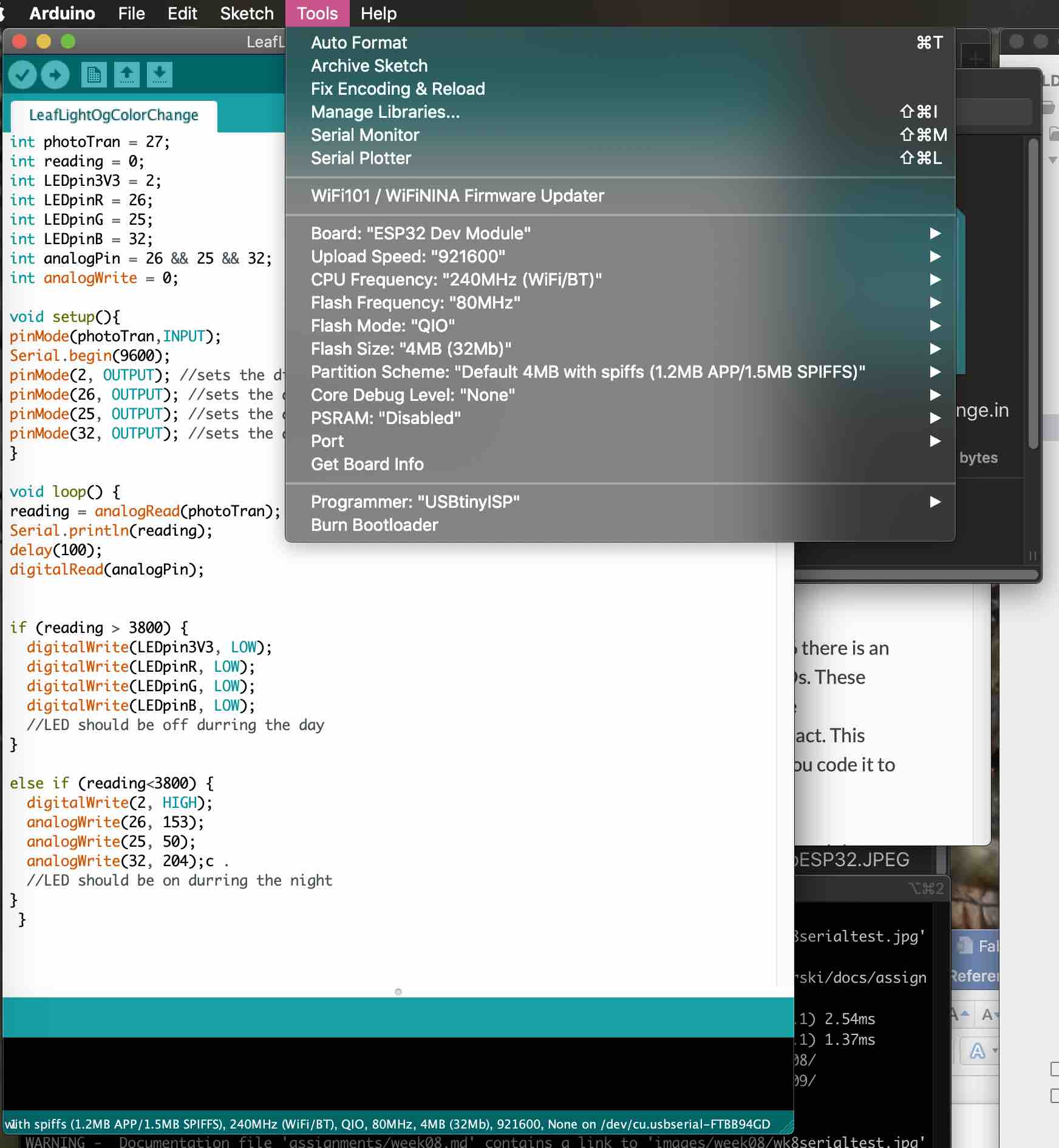
In the tool bar across the top if the Arduino IDE there are 5 options. The second to last is the Tools. This is where the user will set the board type, the upload speed, port, programmer and many other options that can be specifically adjusted to match each individual board.
Arduino uses a check mark button at the top of the program to compile and an arrow button pointing to the right as the upload button. On the bottom portion of the IDE there is a dialog screen that can be used to interpret what is happening in the process.
More information can be found on my input page.
Program
This is the program I wrote in Arduino to communicate with my ESP32 board and control the led.
// Written by Alecia Gorski

//uses a phototransistor reading and transmits to the esp32, this then turns the led on or off
//based on the readings received from the phototransistor

//Fab Academy 2020 (July)


int photoTran = 27;
int reading = 0;
int LEDpin3V3 = 2;
int LEDpinR = 26;
int LEDpinG = 25;
int LEDpinB = 32;

void setup(){
pinMode(photoTran,INPUT);
Serial.begin(9600);
pinMode(2, OUTPUT); //sets the digital pin 2 as output
pinMode(26, OUTPUT); //sets the digital pin 26 as output
pinMode(25, OUTPUT); //sets the digital pin 25 as output
pinMode(32, OUTPUT); //sets the digital pin 32 as output
}

void loop() {
reading = analogRead(photoTran);
Serial.println(reading);
delay(100);

if (reading > 3800) {
  digitalWrite(LEDpin3V3, LOW);
  digitalWrite(LEDpinR, LOW);
  digitalWrite(LEDpinG, LOW);
  digitalWrite(LEDpinB, LOW);
  //LED should be off during the day
}

else if (reading < 3800) {
  digitalWrite(LEDpin3V3, HIGH);
  digitalWrite(LEDpinR, HIGH);
  digitalWrite(LEDpinG, HIGH);
  digitalWrite(LEDpinB, HIGH);
  //LED should be on during the night
}
 }
Once the code was uploaded I was able to interact with the phototransistor to control the rgb led to turn on and off.
Explaining Code
void loop ()
- represents that the function is not expected to return information
if () … else if ()
- this is a statement that communicates to do a specific function under a specific setting, when not in that use is otherwise always assigned to the else function
digitalWrite()
- when the pin is set as OUTPUT it can be set to HIGH or LOW with this function
pinMode()
- sets the pin assigned to act as an INPUT or an OUTPUT
analogRead()
- takes the read of a specific set pin, pin must be analog
How the Code Works
-
pinMode(photoTran,INPUT) tells me that my phototransistor will be the expected input.
-
This input reading will then control when the LED pinMode is HIGH or LOW (otherwise known as on or off) with the digitalWrite() function.
-
int function tells the me which pins are assigned to what functions so that my program directly communicates with the phototransistor or LED (on this project).
Final Results
Python Language
Python is arguably one of the most notable programming languages being used today. Python can be found used in both educational and industrial settings. This language I found much more difficult to learn. I believe with the previous influence and comfort with Arduino partly biased my frustration. The more I worked with it the more it made sense. I would like to do more work with this program in the future.
IDE
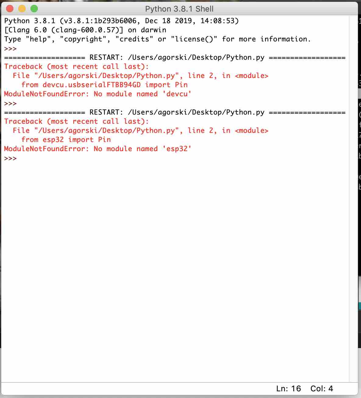
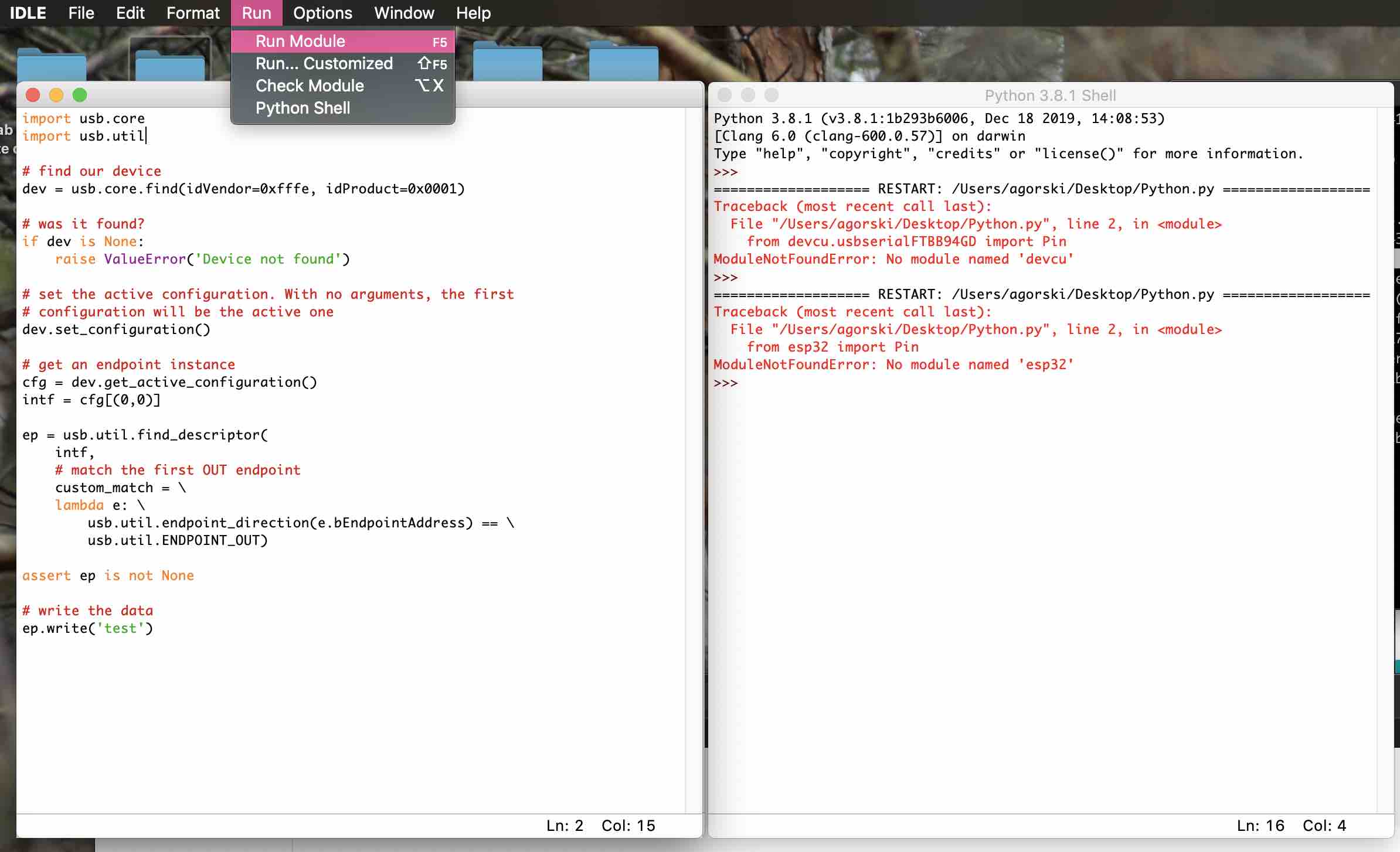
In Python there are many ways you can control the program to interact with your board. Additional downloads can be completed to control the way you interact with the software. The first was I used Python I worked with the IDE IDLE. IDLE is how python interfaces with the user to communicate with the board. The shell is pythons priamry window. This is the window that reads the results of your interactions. This also acts as the debugger and alerts the coder of the errors that can be detected. The image below shows the Python is in the Shell 3.8.1. The arrows indicate the connection is ready to be used.
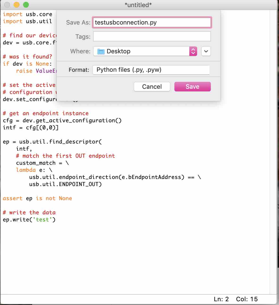
To write the code that interacts with the mcu you have to create a new file. By working in IDLE the programmer can choose the File option in the top left tool bar. This has a New File option and creates a blank screen called untitled. This is now the workspace that the programmer compiles their code in. Once the programmer is satisfied with the code created they must run the program. By choosing the Run option in the top middle of the tool bar addition options appear. The option that reads “Run Module” should now be selected.
Once selected the software will prompt the programmer to save the file. This should be saved in a safe place and titled with a .py extension at the end. This is important so that the program knows it is a python file and reads it as a python file.
This file is what will then be uploaded to the mcu to tell the board what to do.
Program
This however is not how I decided to communicate with my esp32. On further research I found an option that I preferred to use instead. I connected my ESP32 board I created to the usb on my laptop through a rainbow 6 pin header cable. I then powered it with the rechargeable circuit.
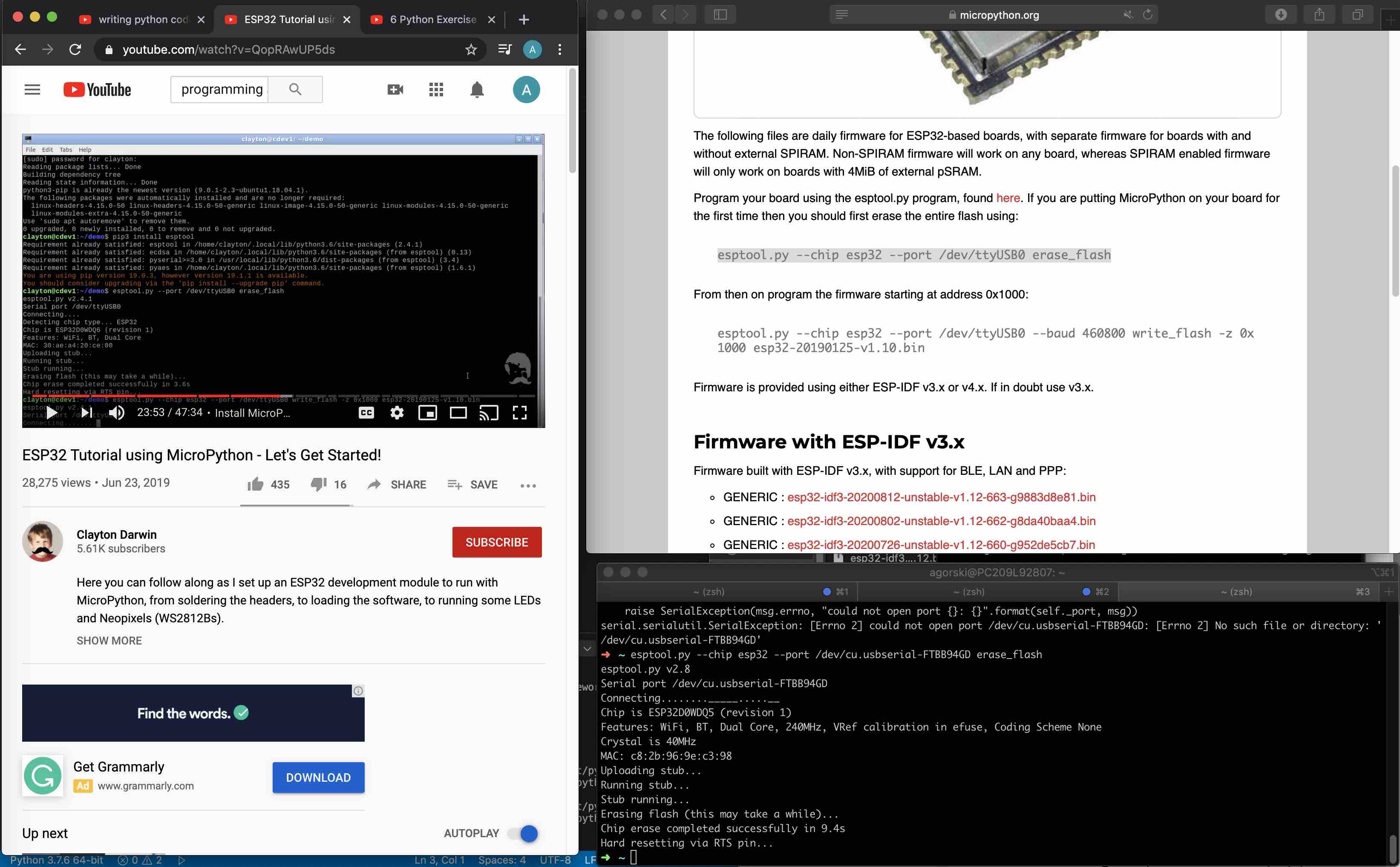
The first step after completing the connections was to Erase the Flash on the esp32. This was completed by entering the following code into the terminal of your computer system:
esptool.py --chip esp32 --port /dev/cu.usbserial-(my serial port label) erase_flash
Once this command was run the results were sucessful as seen in the terminal depiction below.
- Chip erase completed successfully in 9.4s -
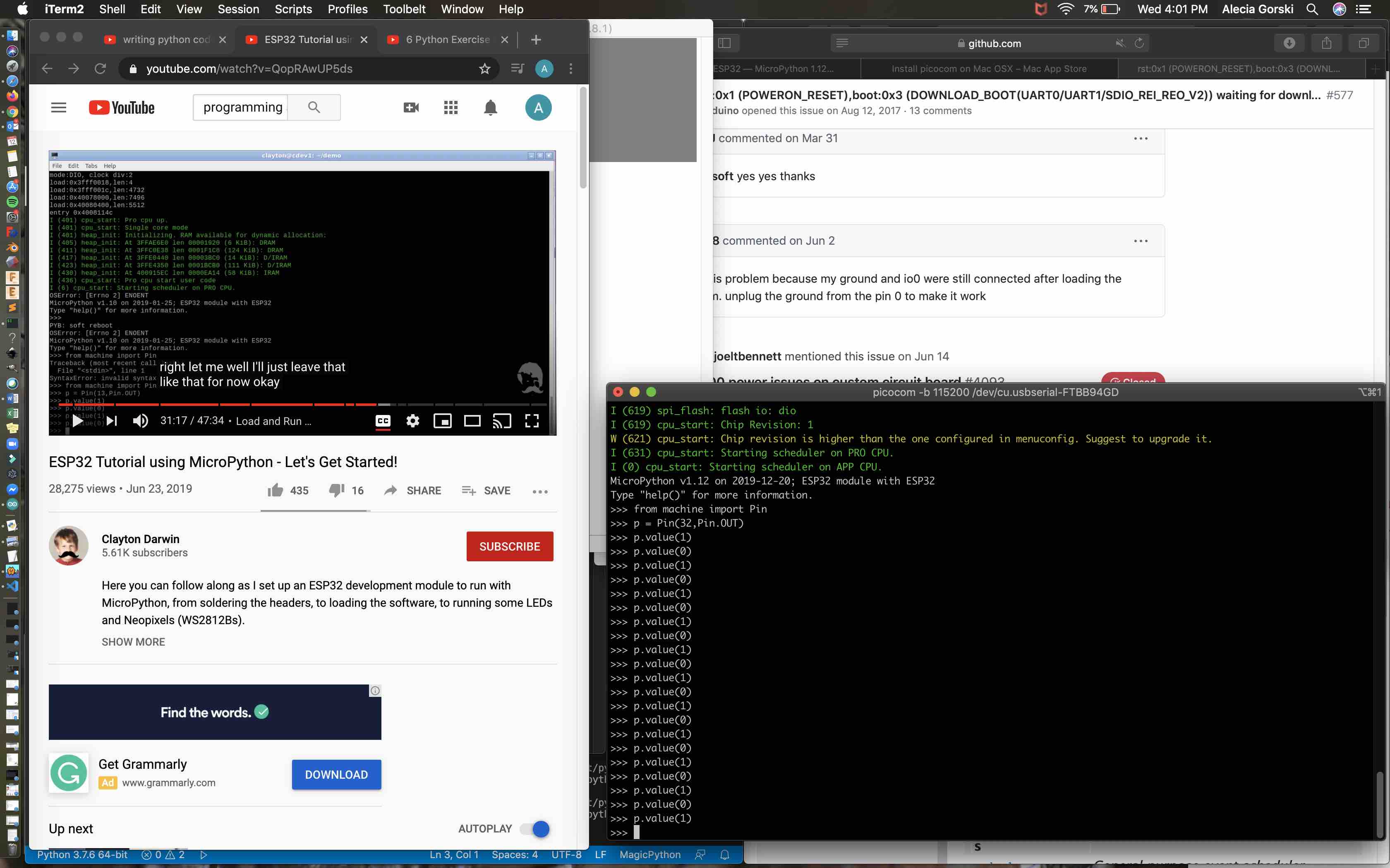
The next step was to install Picocom to interact with the esp32. I was able to find a install link to aid me in this process. I used my terminal to install Picocom by using the command line:
brew install picocom
The command worked because I have previously installed Homebrew. -Homebrew is a program that allows an iOS operating system to install many different packages in the terminal command lines. I did have to update homebrew before use.
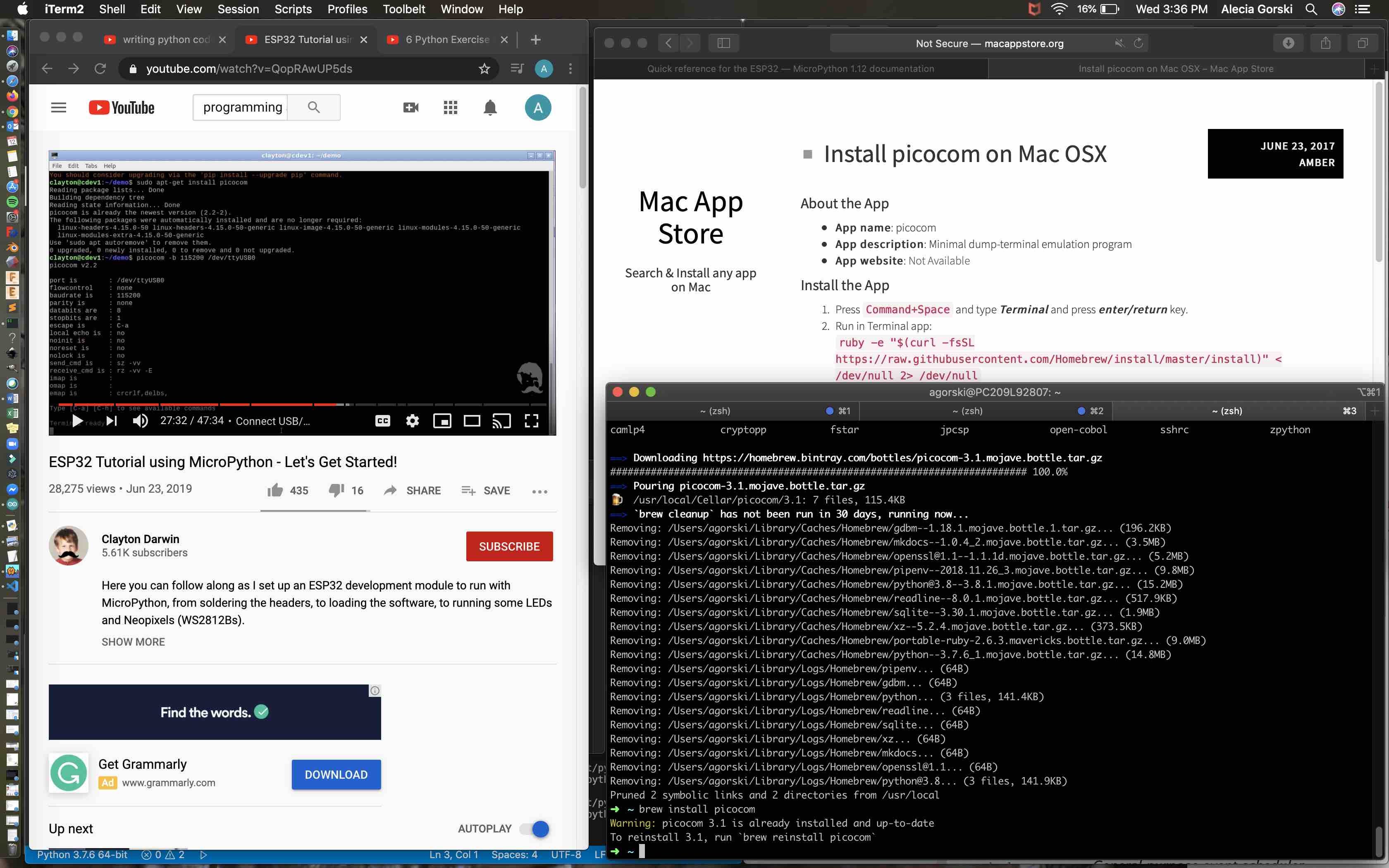
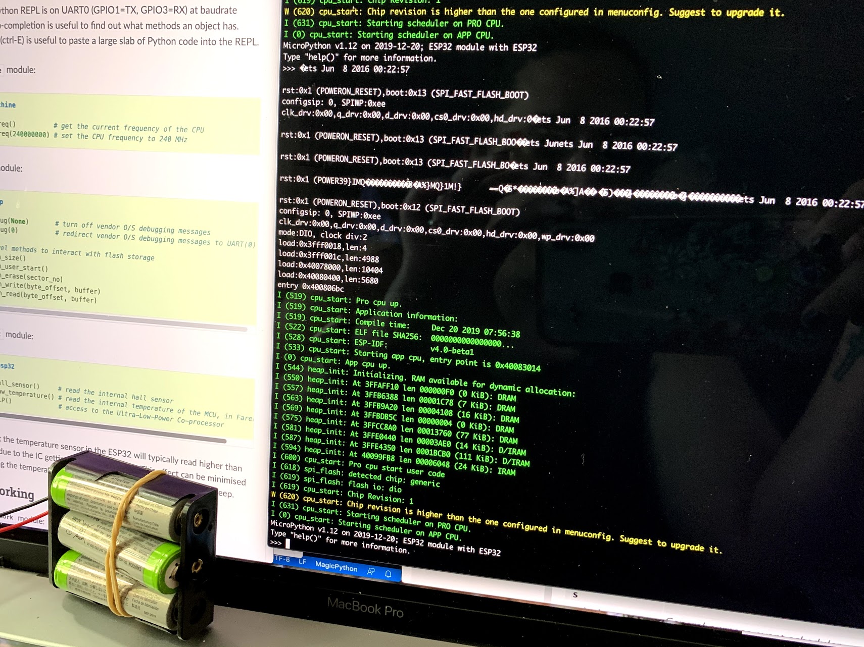
WIth Picocom successfully installed I was able to connect to my esp32 chip and update the firmware. Using the Micropython firmware .bin files I was able to download the correct one for my iOS.
- As a note here I ran into a bit of a problem that was easily fixed when I realized what the issue was. I was receiving an error after downloading the file and running the code that the .bin file directory couldn’t be found. I moved the file to my desktop and this did not work. Then realizing it needed to be in my main used I moved it and the command worked.
I used the command:
esptool.py --chip esp32 --port /dev/cu.usbserial-(my serial information) --baud 460800 write_flash -z 0x1000 esp32-idf4-20191220-v1.12.bin esptool.py v2.8
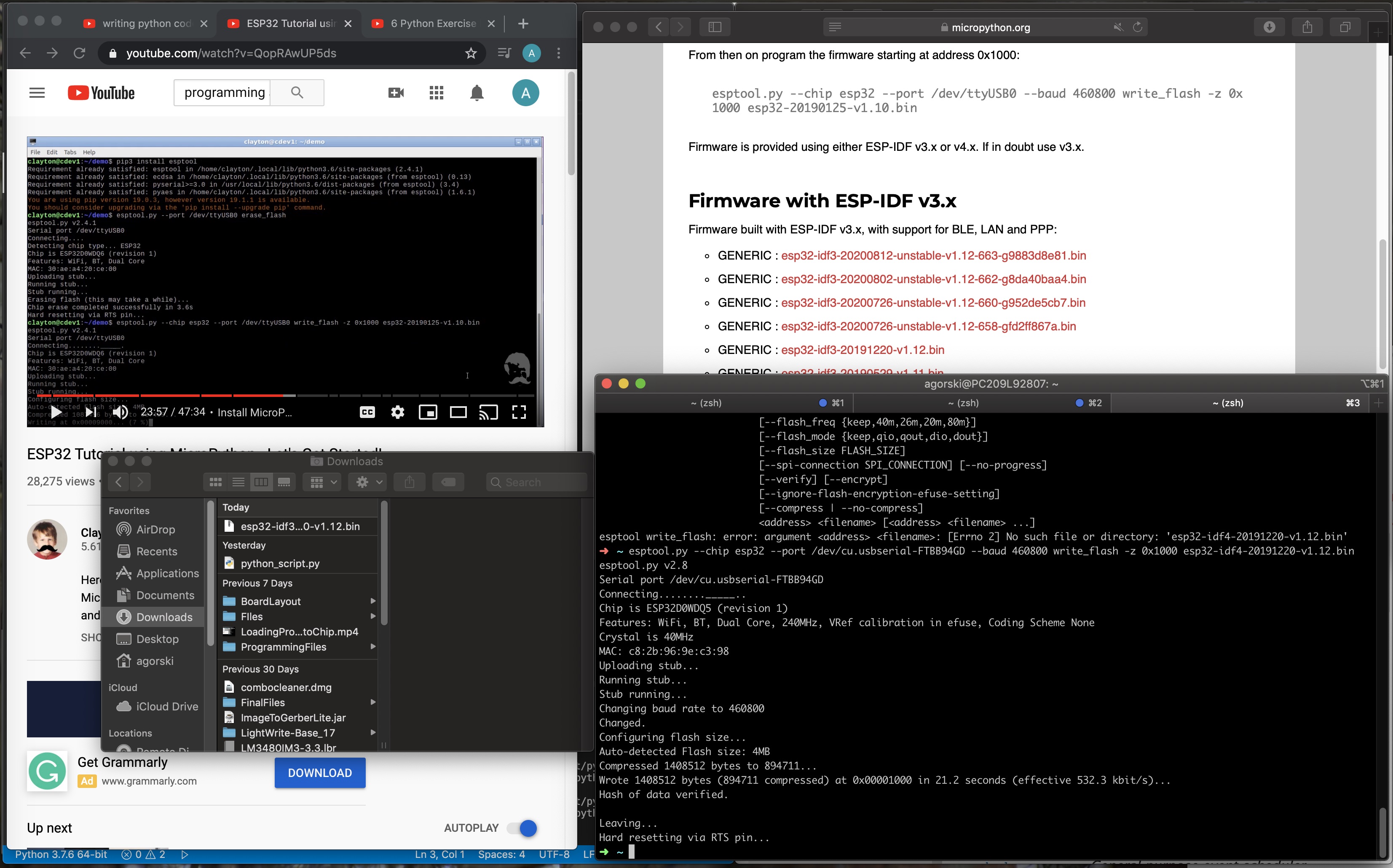
The connection was successful! The bottom terminal message reading Hard resetting via RTS pin… confirmed the connection.
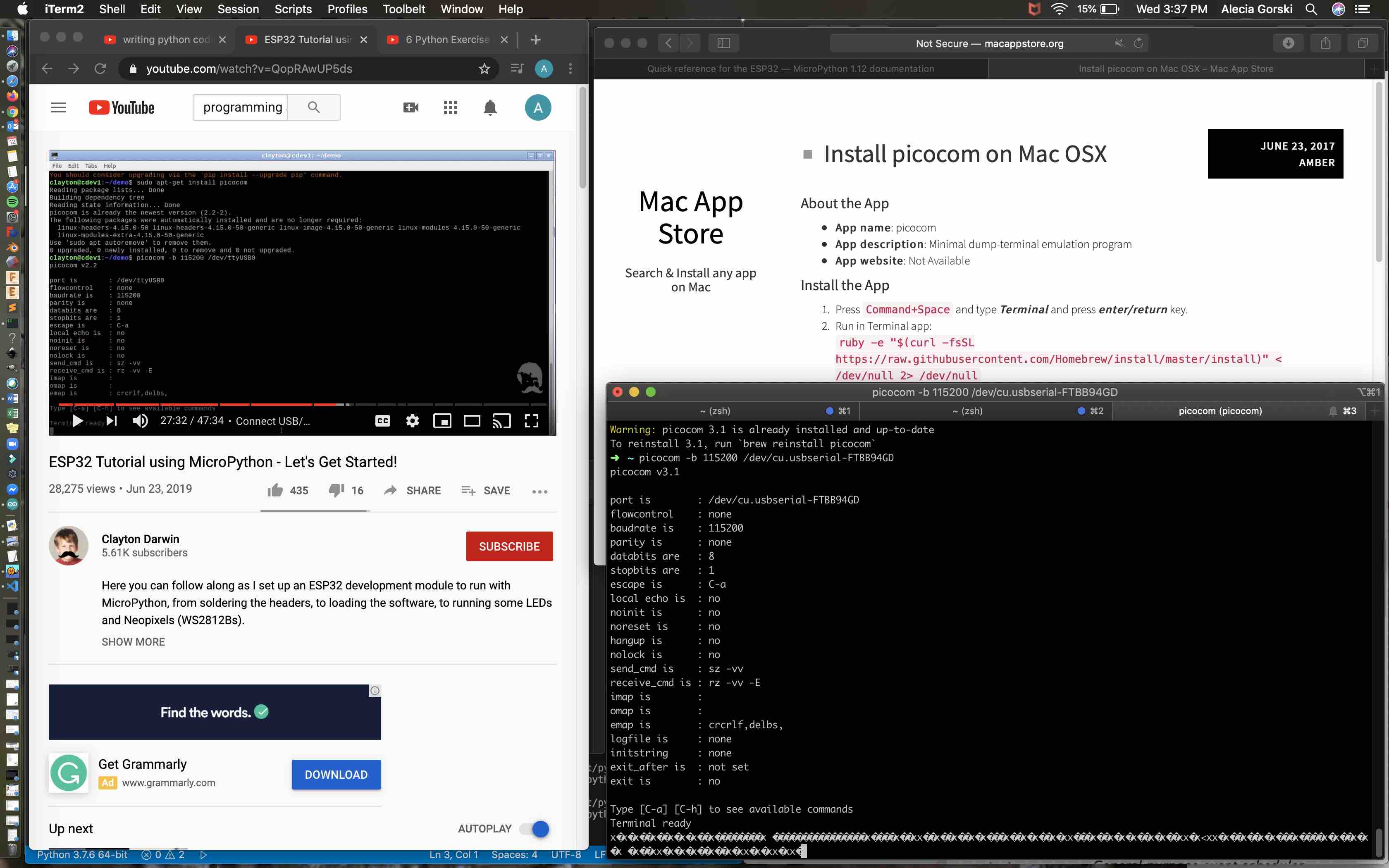
I now used Picocom to connect to my esp32. Using the command:
picocom -b 115200 /dev/cu.usbserial-(my serial port)
When the terminal updates with a Terminal ready message the programmer is good to go! This screen will now be indicated with three arrows in the command line entry point just as python does.
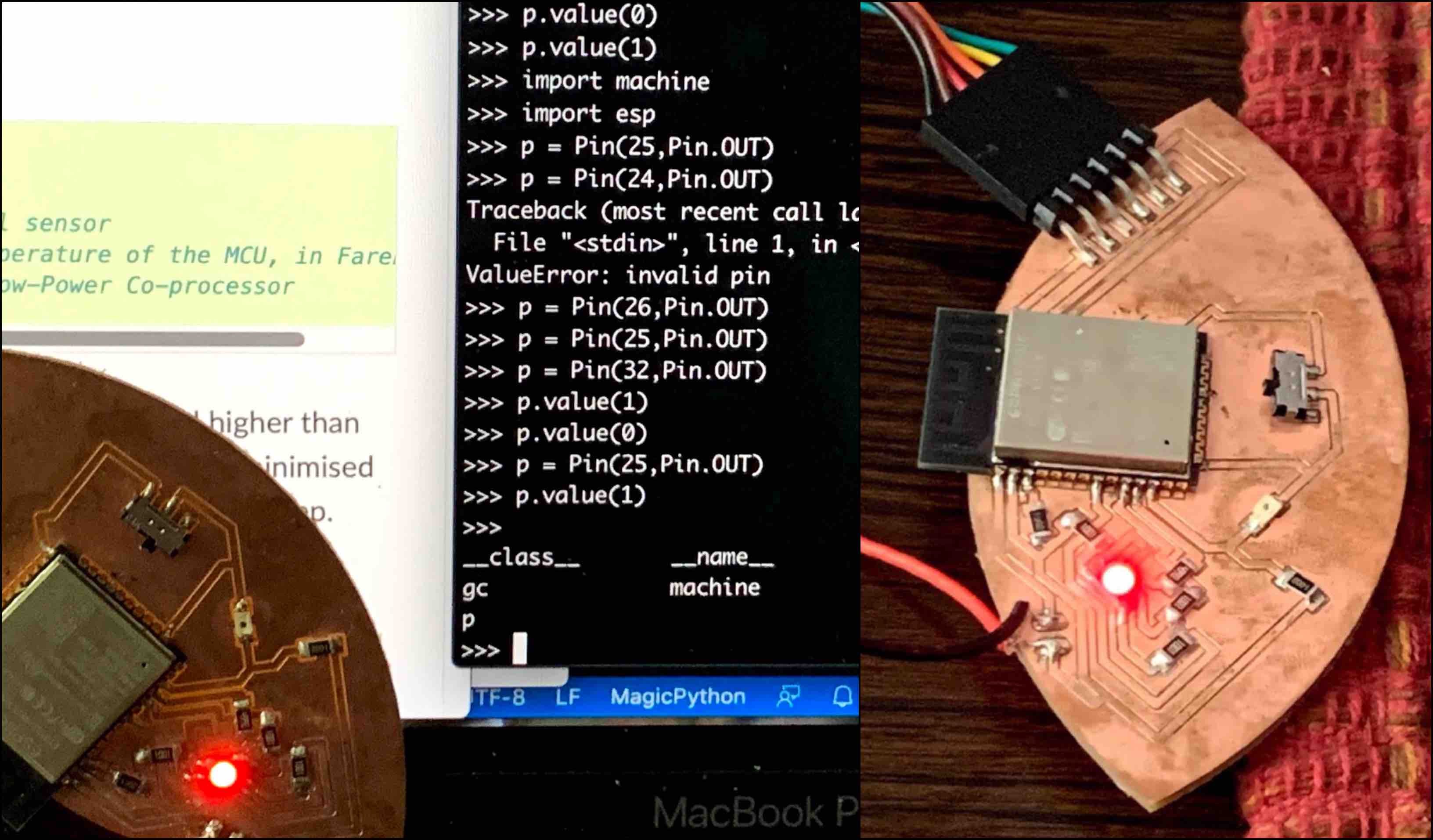
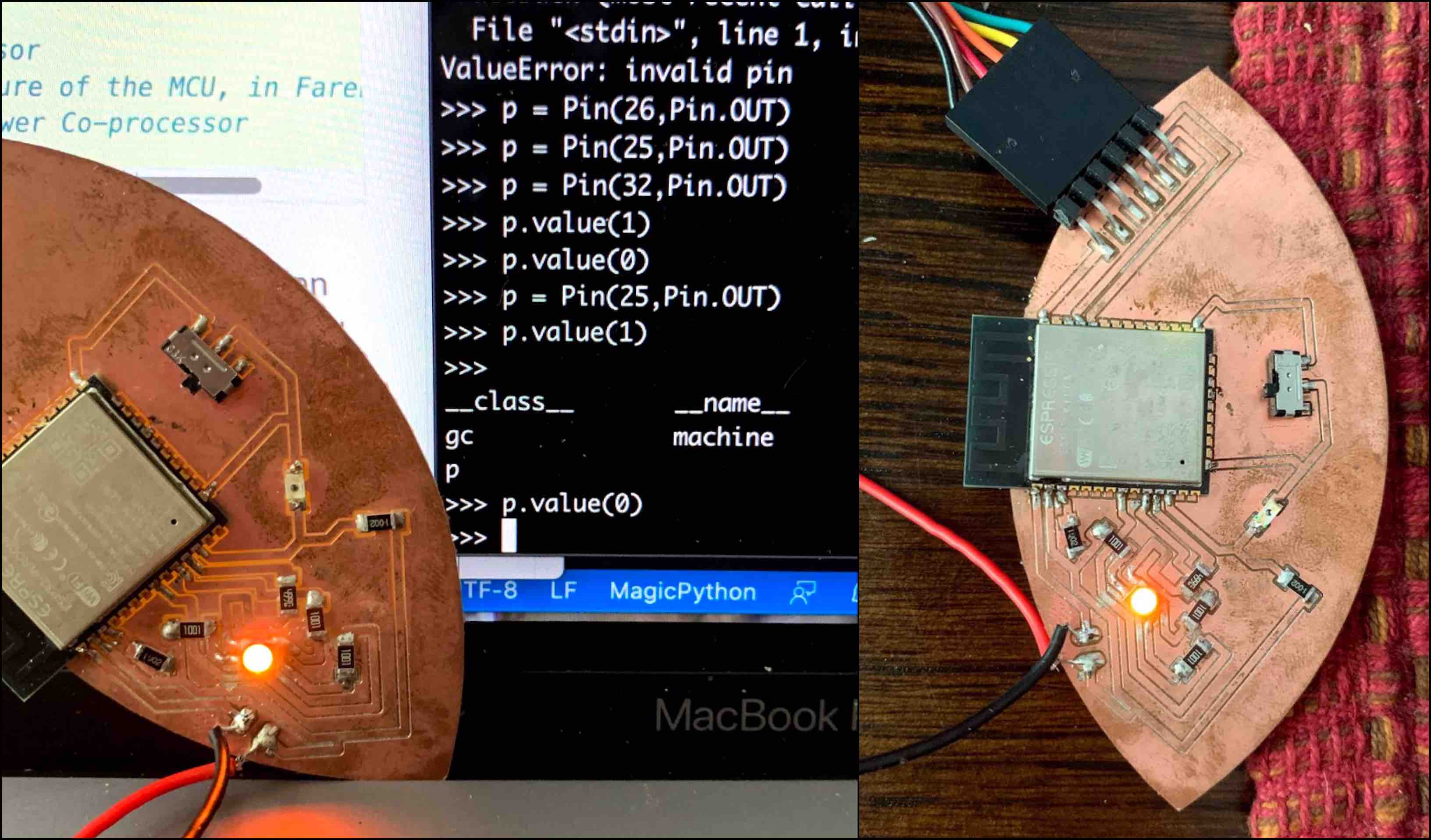
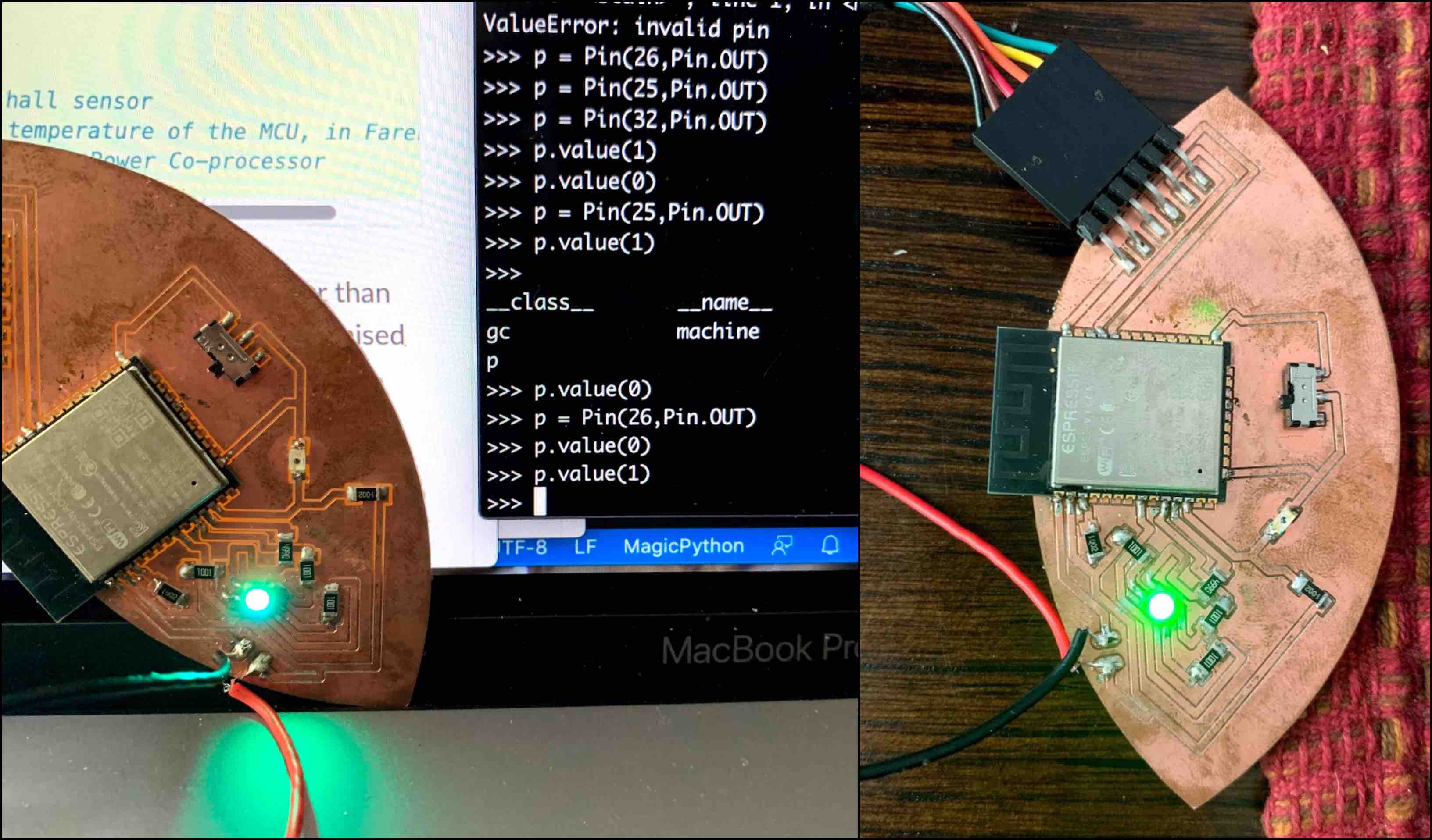
Coding in python I controlled the led with the esp32 by typing in two lines:
from machine import pin
&
p = Pin(32,Pin.OUT)
- In python there has to be a way to specify where you are connecting. By using the command “from machine import pin” I am actually communicating two things: from machine is to connect to the chip through my machine and import pin programs what I am controlling.
Now that each line has been coded to the esp32 the blue pin32 on the rgb led lit. I was able to turn it on and off using two addition commands:
p.value(0)
&
p.value(1)
This can be done with each pin color in the rgb led and can be controlled together creating mixed colors.
The last helpful note I picked up while learning python was the resetting method. My board did not make use of a reset pin. However, by simply breaking the power connection temporarily, when reattached it hard reboots the chip. This can be seen below indicated by the reboot of MicroPython at the bottom of the command lines.
Final Results
As seen in the photos below I was able to adjust the rgb led colors by mixing the rgb pins. The terminal screen shows Red is assigned to pin 25, green is assigned to pin 26, and blue in assigned to pin 32. By turning them on and off with the p.value() I can control the mixing of the three colors.
The video that follows shows the values being turned on and off when entering and changing the p.values(0) or p.value(1).