12. Output Devices
This week I worked on better understanding output devices.
Useful links
Research
The assignment was to add an output/input device to a microcontroller board you’ve designed, and program it to do something. However, under the current COVID-19 quarantine and shut down we do not have lab access at the moment.
In place of the device I made I used an ESP32 Development Board and breadboard set up with the other necessary components.
Arduino RGB Color Control
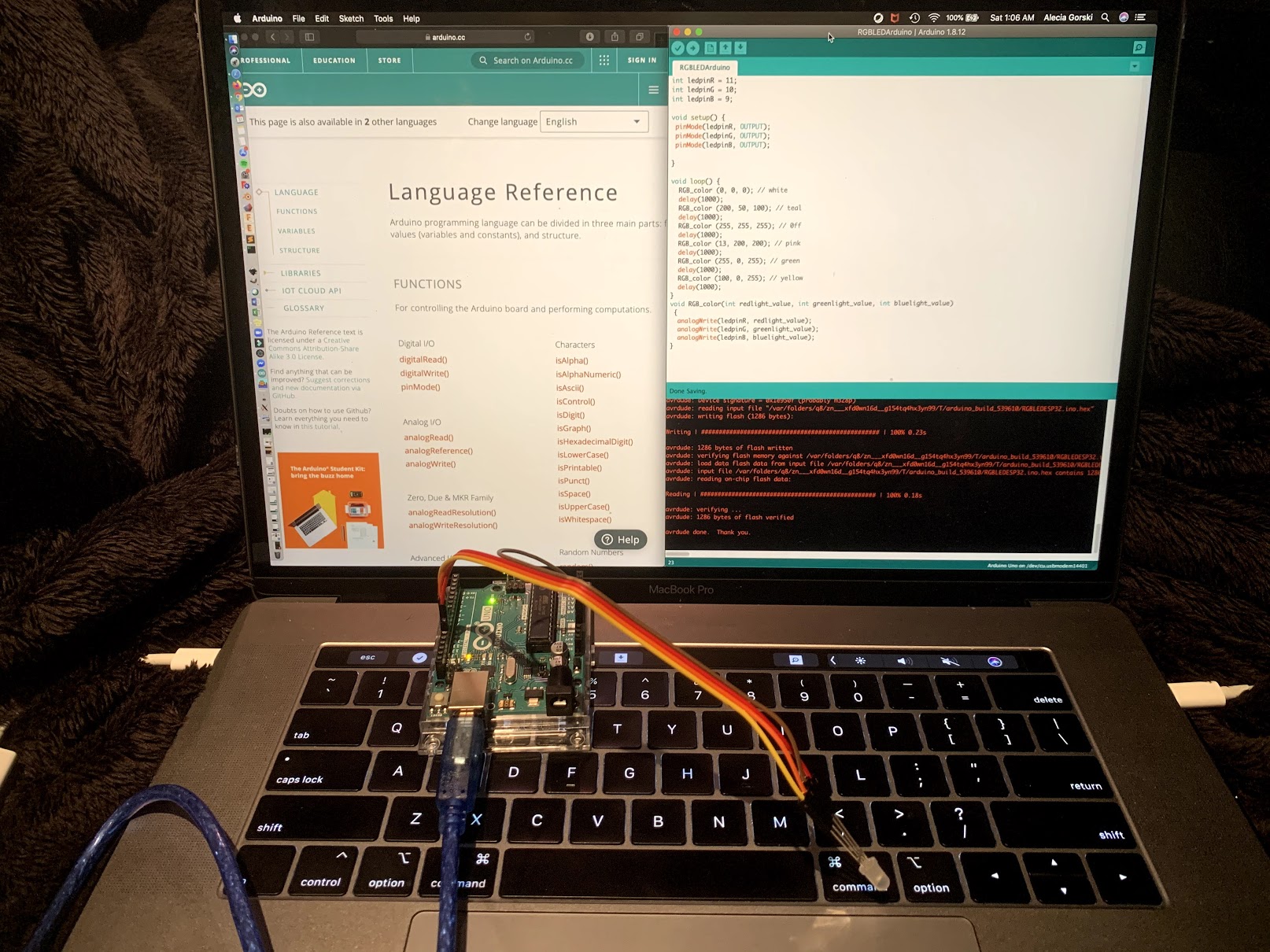
Again I wanted to apply this assignment to my final project Leaf Light. Knowing I want to use an RGB LED so that the user can change the color of the light being admitted through an application on the phone, I decided to test a circuit for this.
Using the ESP32 Development Board, RGBLED, resistors, pwm pins on the microcontroller and the Arduino software to upload the code I tested the function and was very pleased to see the light changing color. I want to apply this function to my final project through the use of a microcontroller.
Arduino RGB LED controlled by PMW Pins
// This code was written by Alecia Gorski. I referred to multiple other proven working codes.
// I combined the aspects I learned along the way and based my code off working with an Arduino Uno.
// October 31, 2020

int ledpinR = 11; //Setting LED pin number for red
int ledpinG = 10; //Setting LED pin number for green
int ledpinB = 9; //Setting LED pin number for blue

void setup() {
 pinMode(ledpinR, OUTPUT); //setting pin to provide an output
 pinMode(ledpinG, OUTPUT); //setting pin to provide an output
 pinMode(ledpinB, OUTPUT); //setting pin to provide an output

}

void loop() {
  RGB_color (0, 0, 0); // white
  delay(1000);
  RGB_color (200, 50, 100); // teal
  delay(1000);
  RGB_color (255, 255, 255); // 0ff
  delay(1000);
  RGB_color (13, 200, 200); // pink
  delay(1000);
  RGB_color (255, 0, 255); // green
  delay(1000);
  RGB_color (100, 0, 255); // yellow
  delay(1000);
}
void RGB_color(int redlight_value, int greenlight_value, int bluelight_value)
 {
  analogWrite(ledpinR, redlight_value); // defines values for each color
  analogWrite(ledpinG, greenlight_value); // defines values for each color
  analogWrite(ledpinB, bluelight_value); // defines values for each color
}
Explaining the Code
For this assignment I used the Arduino Uno to control an RGB LED. My project goal is to be able to change the light of the RGB LED on my own board.
This changing of the RGB values within the LED via coding is controlled with PMW pins (pulse width modulation). Arduino does a really great job explaining the concept. In short specific pins on a microcontroller are assigned with the function of being a pwm pin. As long as the RGB LED pins are assigned to the PMW’s then they should be able to be coded with a value ranging from 0-255. Each of the R, G and B can be changed within that range. RGB_color() in the code above has a series of 3 values. Each of those represent a percentage relating to that specific pin. This percentage stands for the length of the pulse being provided through the microcontroller and appears to the user as brightness in the LED.
- As a note, PWM is a form of controlling the power but when in relation to LEDs it controls the brightness.
int function assigns each of the pins so that the code knows how to link each pin to the correct component. “int” stands for integer and is a data type. This data type describes a range of values that are available to be used within that specific variable. As long as the integer fits within that range it can be used. For example, int LEDpinB = 9 means that the variable is an integer being called LEDpinB and its corresponding value is 9.
In this code I used the pinMode() function to assign R, G and B to respective pins. It is important that these are PWM pins. This is so that the pin information can be changed in between a range of values.
I used the RGB_color() function to control the values of the RGB LED. Using analogWrite() I am able to set my pin values to adjust the amount of each color coming through. The different RGB_color() values control how much red, green, or blue is mixed to create the final color.
Code Running
Self Made Board - Phototransistor to RGB LED
My Board and Changing Colors
My board was cut and soldered to be used with the ESP32 WiFi capabilities. Using the WiFi connection I am able to change the colors of the RGB LED with the application interface.
The video, as well as a full explanation on the above reference, compatible code and its explaination and further documentation can be found on my input page.
Problems and How I Fixed Them
…can be found on the Final Projects Development Page. This is where I have documented the development of my board and any complications I may have come across.
Files
Files used in Output Week can be found in the File Zip for the final project.