18. Mechanical Design and Machine Design
This week we worked with our local team to determine what type of machine we might want to make.
Research
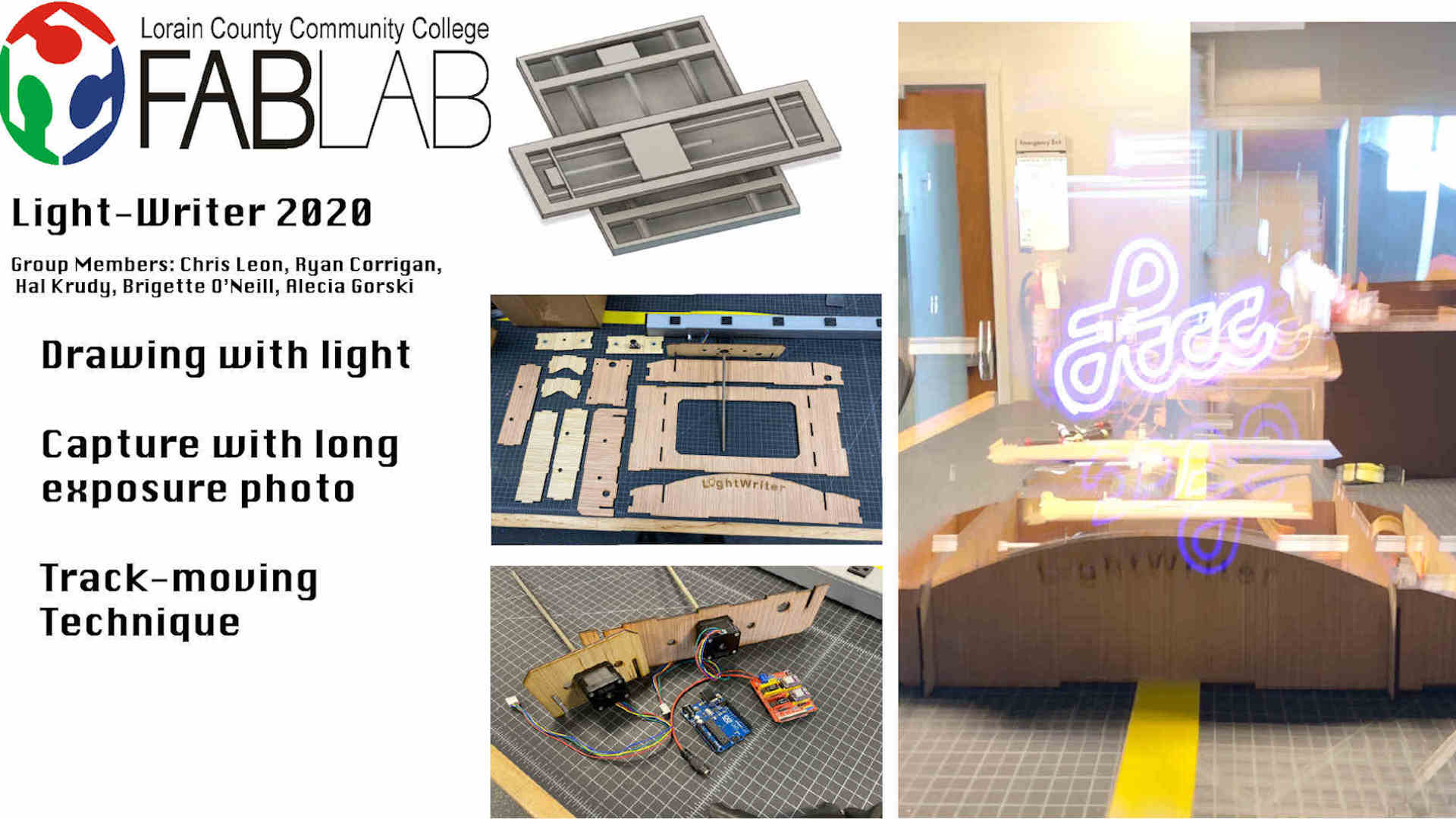
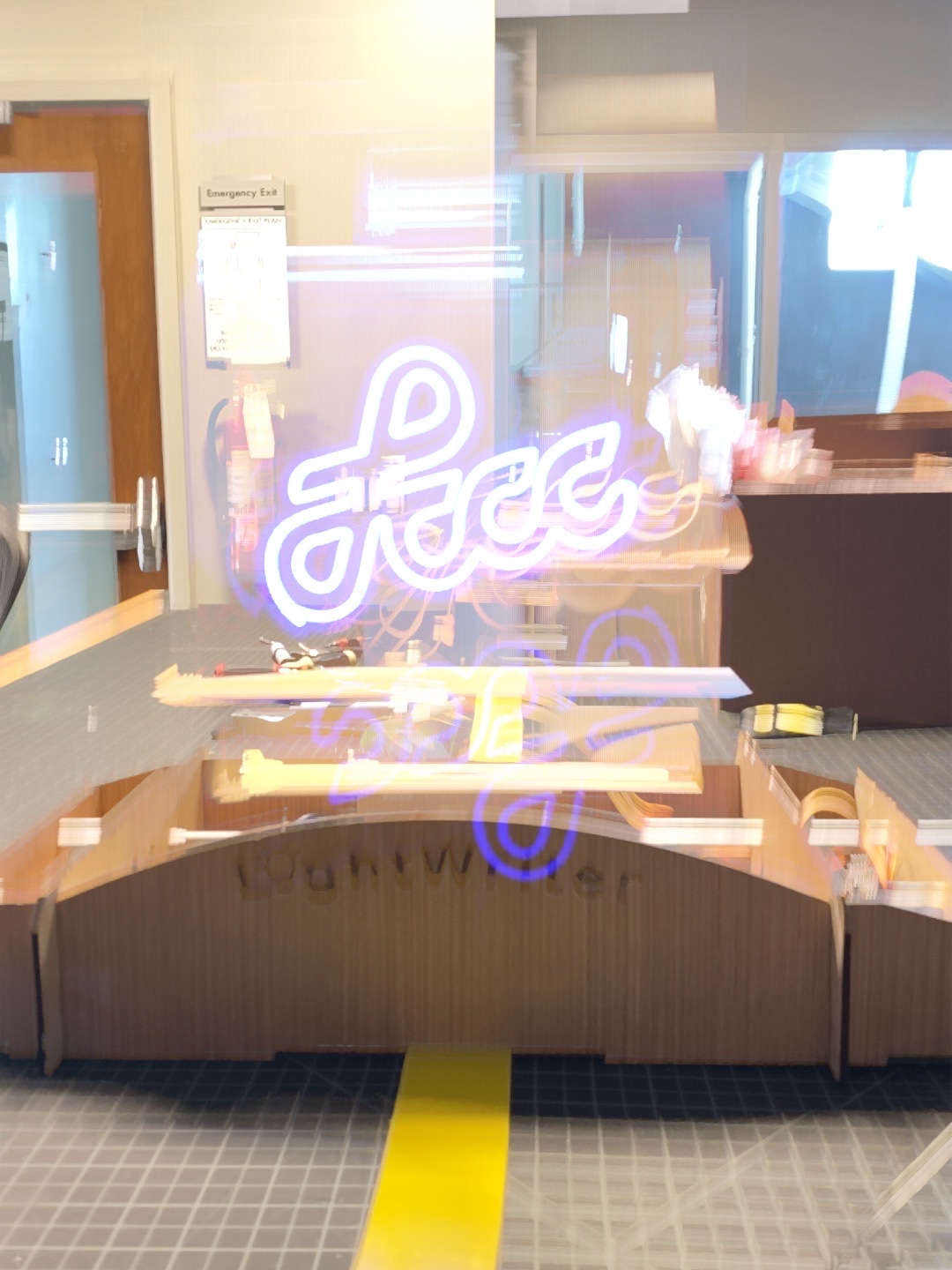
Meshing interest in machine design and photography techniques we decided to create a 2-axis machine that could follow G-Code and create light drawing with a long exposure. By using a light mounted to our machine, the 2 axis can move along the lead screws of the step motors. This will allow the light to follow the axis as they communicate with the step motor through a wired connecting. The G-Code will tell the step motors when to move and how. The light will then be tracked by the long exposure of the camera. A Nikon D3400 is being used here.
Individual Student Site Links for Further Documentation and Details
- Alecia Gorski Fab Academy Site
- Christopher Leon Fab Academy Site
- Hallie Krudy Fab Academy Site
- Ryan Corrigan Fab Academy Site
- Bridgette O’Neill Fab Academy Site
Contributions:
Alecia- Fabrication + Assembly + Presentation
Chris- Mechanical Design + Electronics + Fabrication + Assembly
Hallie- G-code/Image + Fabrication + Assembly + Presentation
Ryan - Video + Fabrication + Assembly
Bridgette - Slide
Video -Ryan Corrigan
Slide -Bridgette O’Neill
Planning Stage
For the planning stage we faced a few complications. Due to the COVID Pandemic meeting on campus at the time was a challenge. We used an app called “Whats App” to communicate. Through this app we were able to all share ideas on what we thought would make for an interesting machine design. Ideas on fortune tellers and arcade machines were all thrown in the mix. As a group we decided that we would choose a light writer!
We then made plans to divide up work and start with digital design. Once the basic build concept was agreed on by the group we divided up the remaining tasks, as well as planned group work days in the calendar that worked for everyone.
The results are as follows.
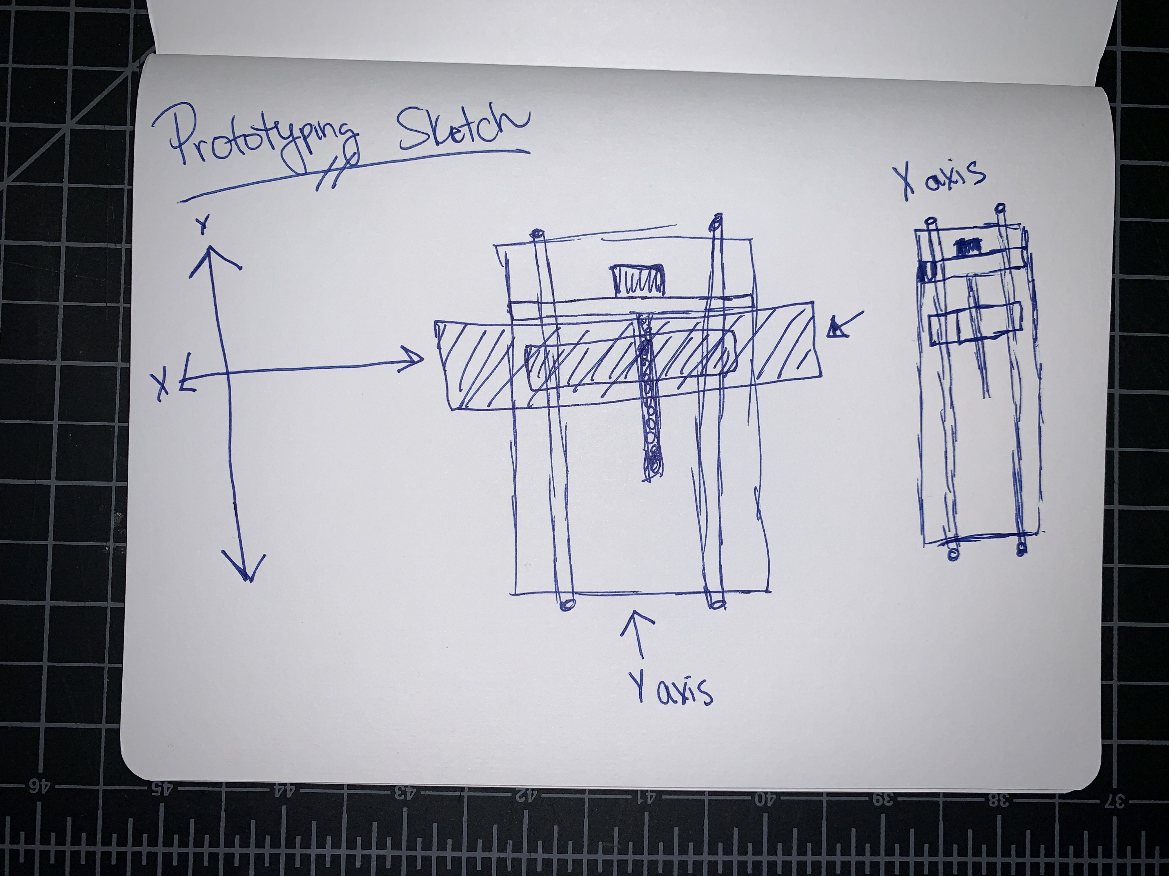
First Prototype
Prototyping Sketch -Alecia Gorski
Animation of Intended Function -Alecia Gorski
The design was created in Fusion 360 and more can be found about this on Alecia Gorski’s page.
Testing Results -Alecia Gorski
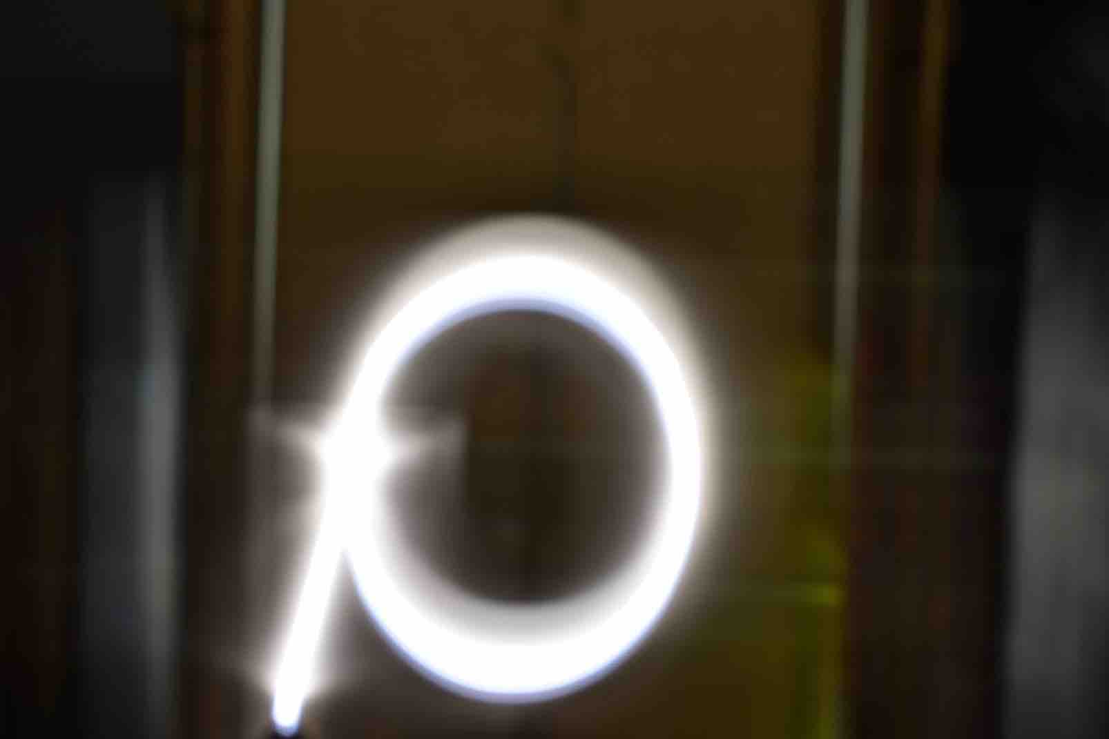
Using the materials we could find in our lab we put together a rough testing of the machine. The motion of the LED with the long exposure created the light design. We started simple with a box.
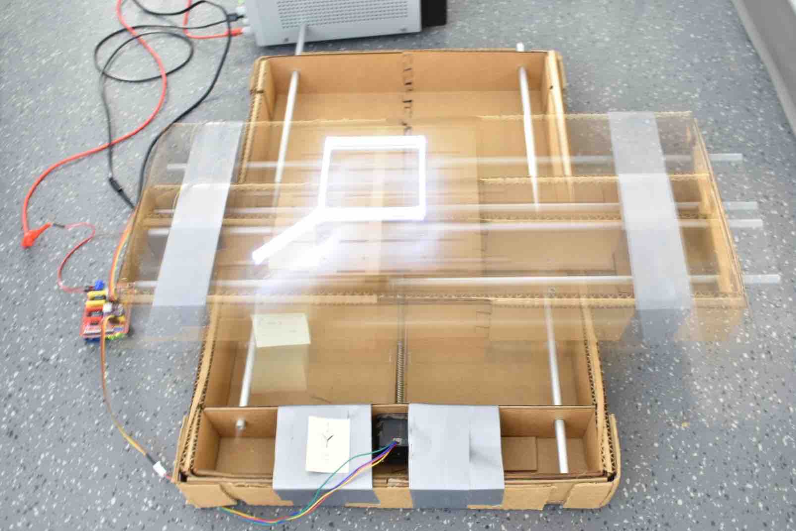
The best exposures can come from being in a darker area. This allows just the light from the LED to be let into the camera during the long exposure.
We were successful in coding the machine to complete a square as well as a circle.

Making the Lightwriter
| Hardware | Arduino Uno with CNC shield v3 |
| Motors | NEMA 17 steppers with built in lead screws |
| Material | Wooden exterior (lasercut) |
| Firmware | GRBL v1.1 |
| Control Software | Universal Gcode Sender version 2.0 Platform (Nightly build) |
| App | Lightmatic (free in app store) |
| Graphics Editor | Inkscape 1.0 (open source) |
Design + Hardware -Chris Leon
Design
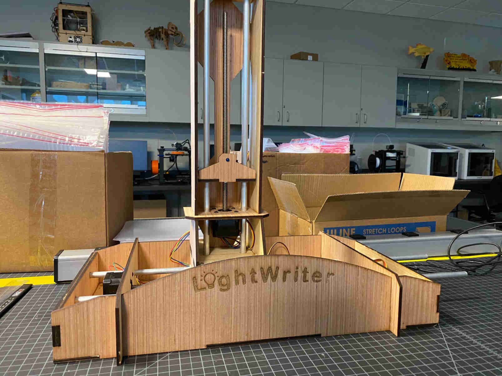
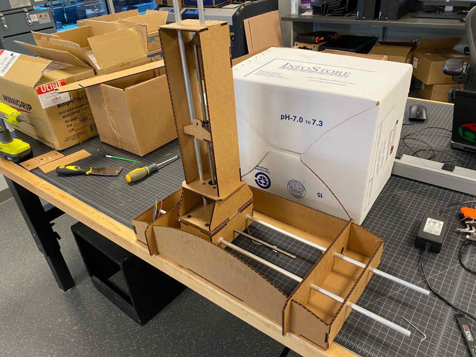
Based on the CNC, the two axis design was originally oriented horizontally. This was changed to a vertical orientation to capture the long exposure effortlessly and display the “writing” process more clearly.
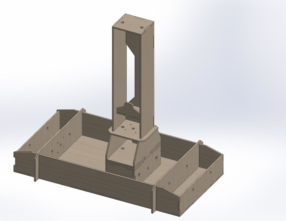
Soldiworks Render of the Lighwriter:
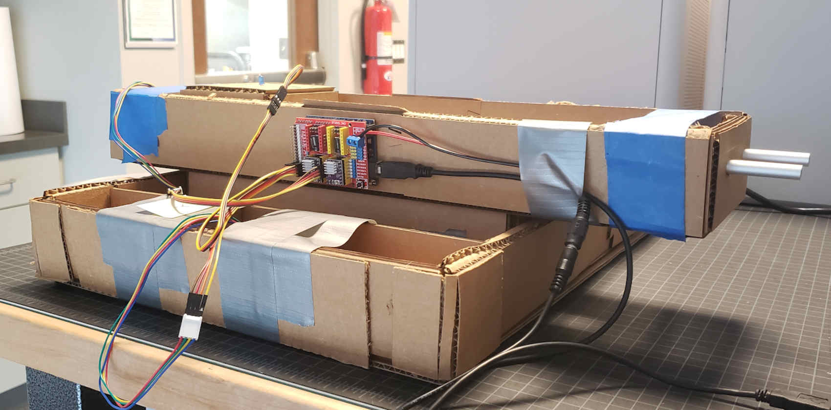
The Cardboard Prototype:
The Second Cardboard Prototype:
Final Version:
Hardware
| Hardware | Arduino Uno with CNC shield v3 |
| Motors | NEMA 17 steppers with built in lead screws |
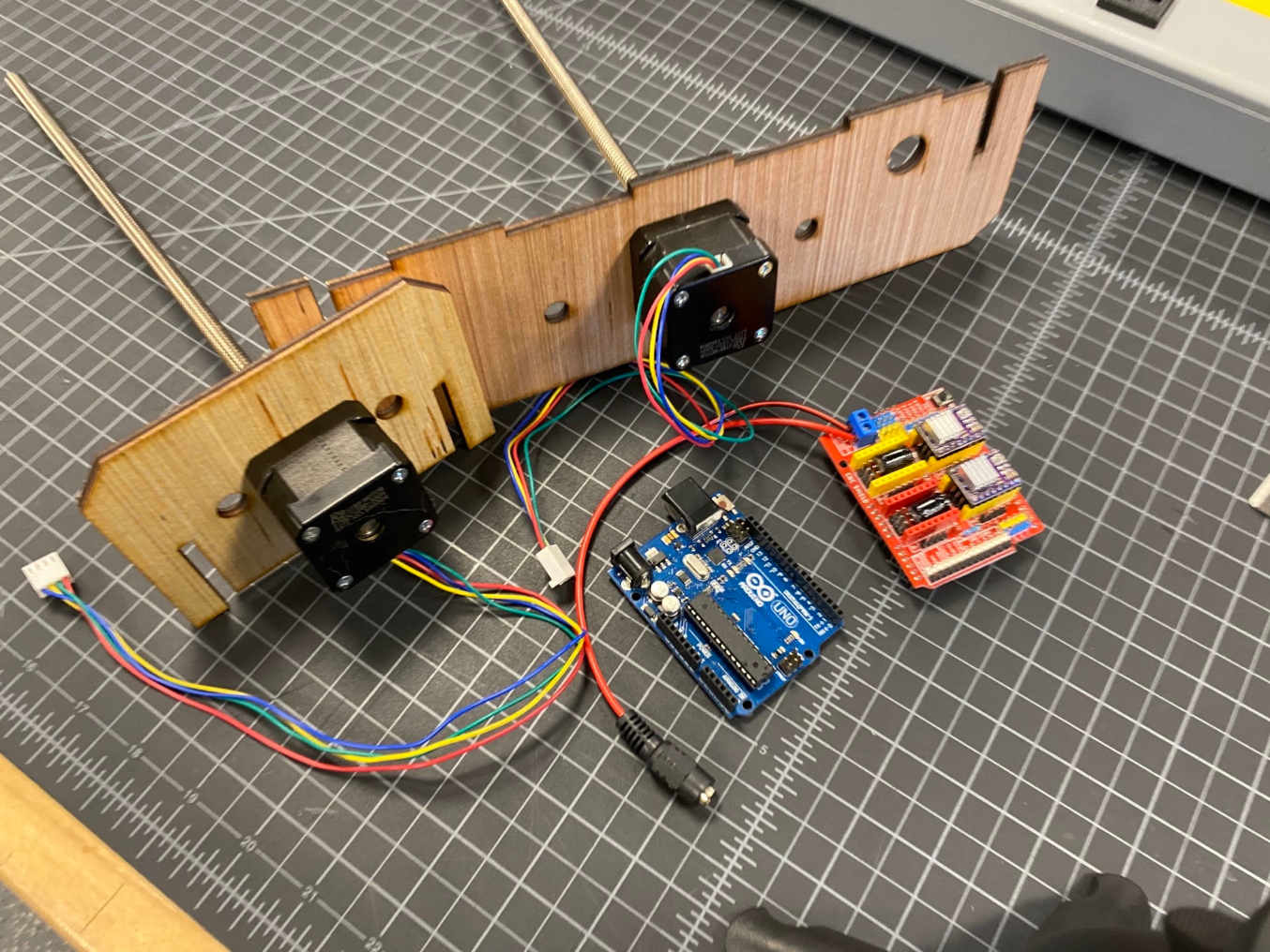
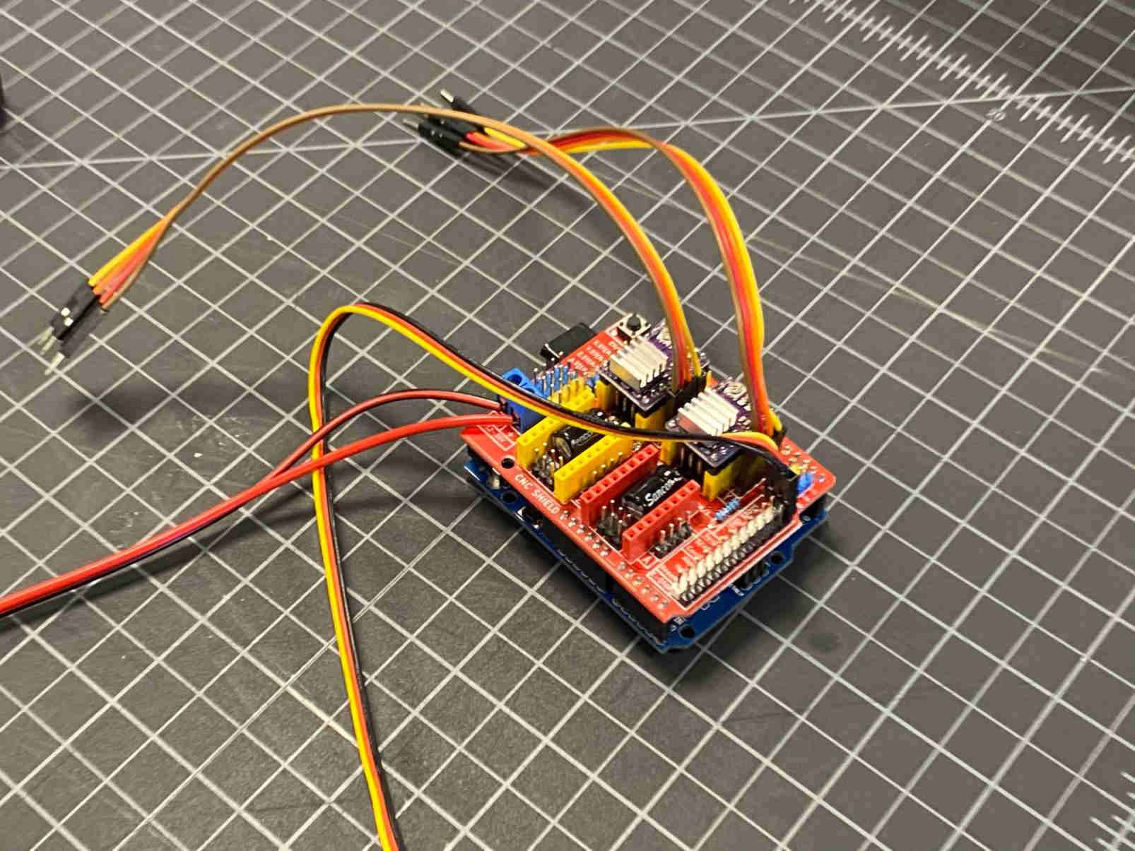
Two NEMA 17 steppers with built in lead screws were used. The stepper motors were controlled by an Arduino Uno with a CNC shield v3. The LED is connected to the spindle speed control pin to allow for the changing of brightness through pulse width modulation. Manual control can be done via the UGS software.
Stepper Motors with Arduino Uno and CNC Shield:
Arduino with CNC Shield
Making the Lightwriter “Write” -Hallie Krudy
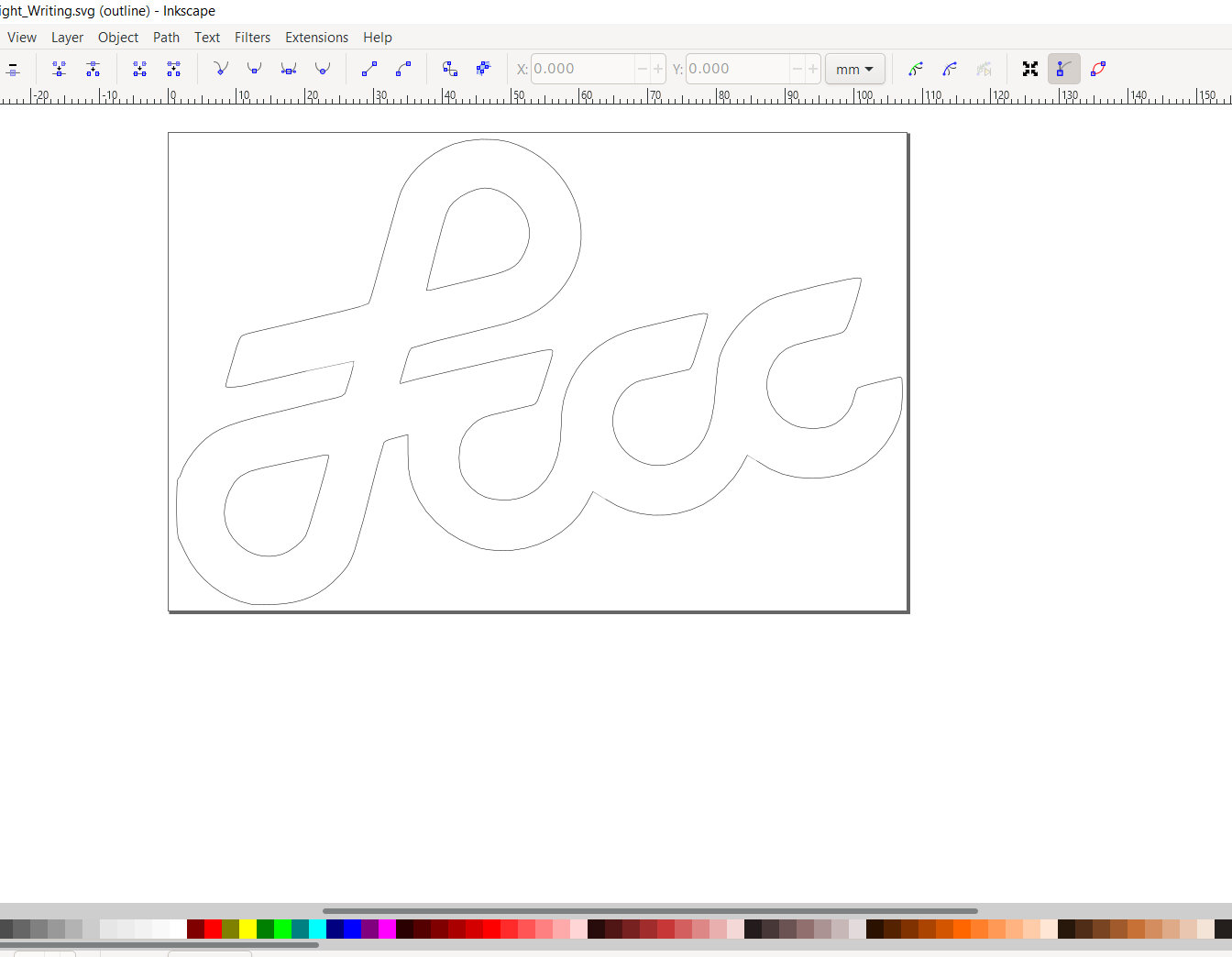
In order to translate the image correctly, we need to use g-code to control the stepper motors that will “write” the image with an LED. That image can be made with a vector graphics editor such as Inkscape or Gimp, which will be capable of changing a raster image to a vector one by creating paths from a bitmap. In the case of the outline, the led will blur out any small imperfections or mistakes within the path.
The image can be opened into a program like laserGRBL, which will produce the g-code and allow us to control the brightness of the LED through power modulation on a PWM pin of the arduino. From there, Universal G-Code Sender (UGS) is used to send the g-code and control the movements of the stepper motors. The control of the stepper motors can be done manually by moving a certain number of defined steps on different axes.
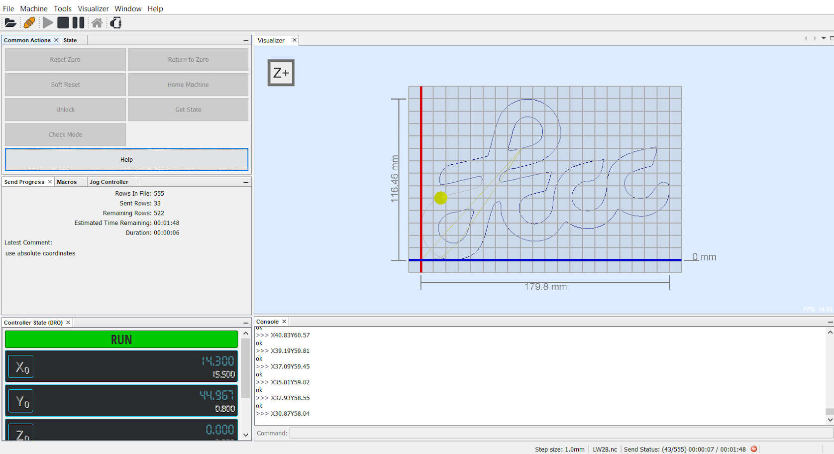
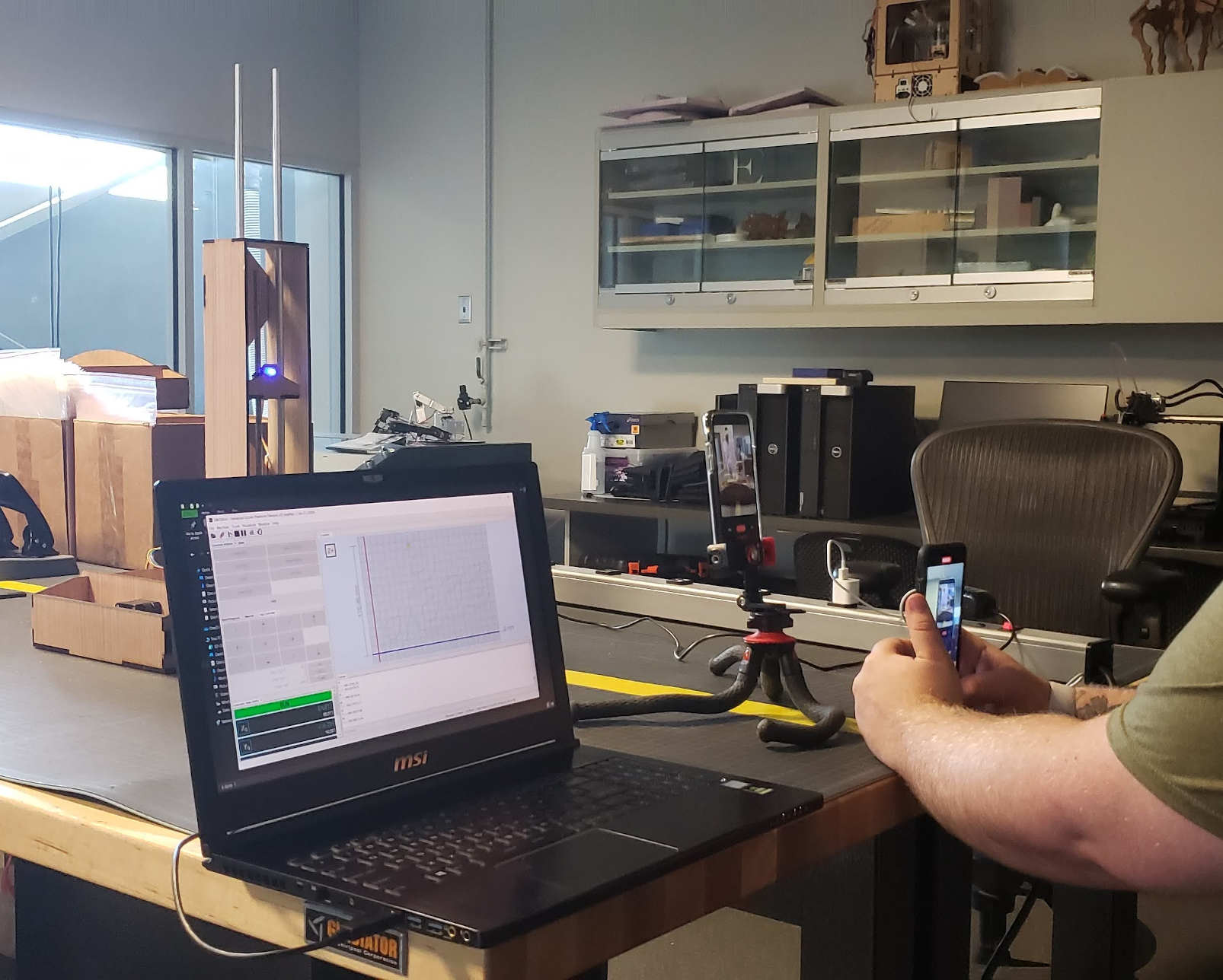
Run the g-code and watch it “write!”
Fabrication + Assembly -Alecia Gorski
Need to Cut the wood down to 18 x 24 inches to fit into Matilda, the laser cutter.
Sheets of Wood:
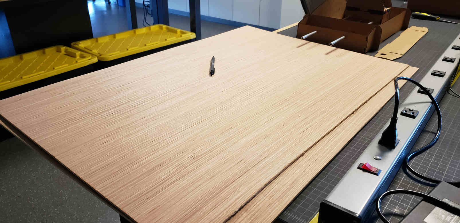
Here is Ryan cutting it down:
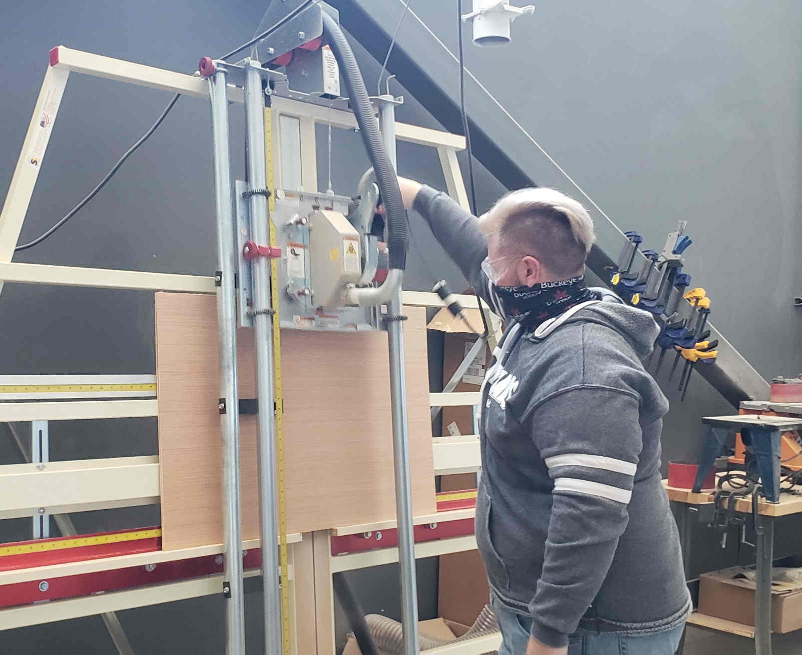
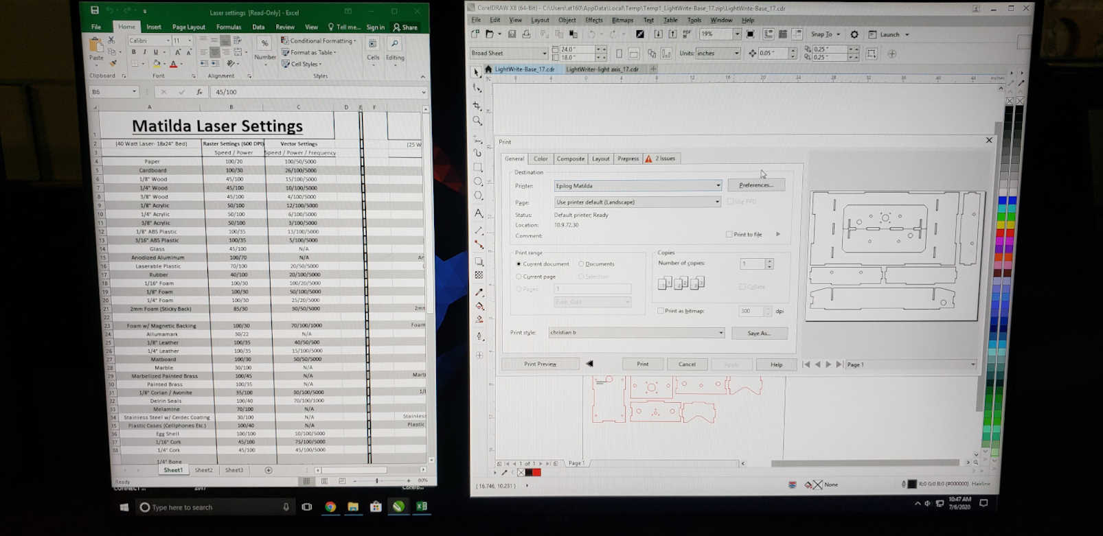
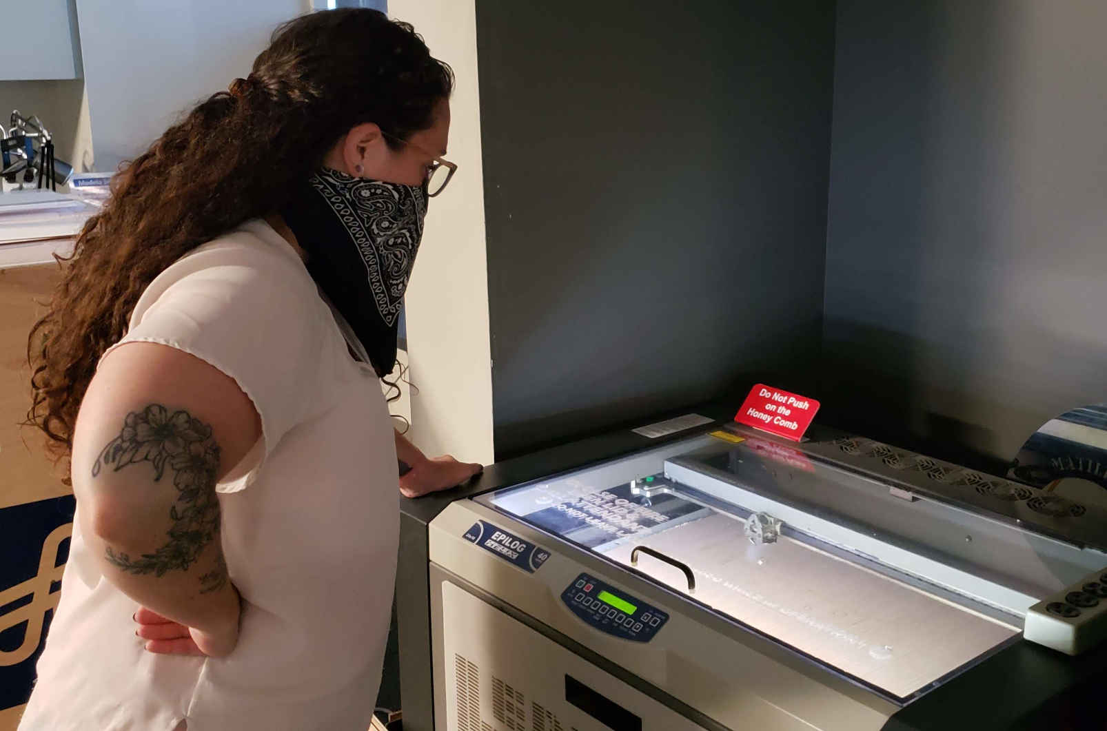
Setting up Matilda to cut the LightWriter pieces out + engrave the logo
Alecia and Hallie took turns watching Matilda for safety (no fire hazards here).
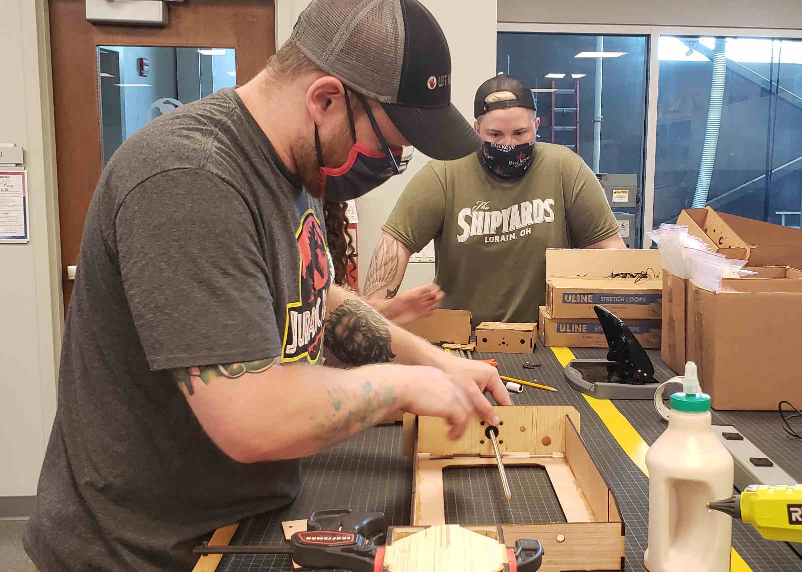
Assembly coming along with Chris, Hallie, Ryan, and Alecia.
Chris and Ryan:
IT’S ALIVE!!
Manual testing
Problems and Solutions
-
Problem: Communication with the Light Writer Solution: Group decided to communicate with G-Code. This was assigned to the coding team.
-
Problem: Board to Run the Machine Solution: I believe we were able to use resources from Chris Leon.
Future Development Opportunities
-
Light Writer - as a toy for anyone of any age. Learn how to code and communicate with a light as you create art.
-
Light Writer - as a company tool. Use the light writer to create and document logos with an alluring look.