4. Computer controlled cutting
Goals
Group assignment Hardware aspects of laser cutter (how-to guide)
Individual assignment:
-
Design, lasercut, and document a parametric press-fit construction kit, which can be assembled in multiple ways. Account for lasercutter kerf.
-
Cut something on the vinyl cutter.
Group assignment
Found here:
Individual assignment
Design a re-configurable, parametric furniture system for small spaces:
Parametric design:
The goal of parametric design is to use as few fixed variables as possible. To accomplish this, parametric design is comprised of three parts; constraints, relations, and dimensions. Constraints are just that, fixed constraints added to a selected geometry. Two examples include; horizontal and vertical Example, if a line segment needsto be vertical no matter what changes are made, the vertical constrain would be added to it. Relations are constraints shared by two or more geometries. Some examples include; perpendicular, parallel, coincident, equal, and more. If several circles need to be the same diameter, the equal constraint would be added to all of the circles. Dimensions are just that, a specified measurement added to geometry. The trick with parametrics is to relate as much geometry as possible to only a small handful of fixed variables. This is typically done with math formulas and spreadsheets. In this project, press fits are going to be used to attach the various pieces together. A fixed variable would be the material thickness. The slot width would be a function of that, adding a separate variable to account for kerf. This is where the power of parametrics shows. If a different material is used, the material thickness variable can be changed and all of the slots would change, saving a considerable amount of time. The same goes for the kerf value. Different materials can have a different kerf, so being able to change all geometry with only one input is quite handy. The software I’m using for this project is going to be SolidWorks. In the previous section, I detailed the work flow of the software, so here all focus more on the parametric aspects.
First, draw the main panel:
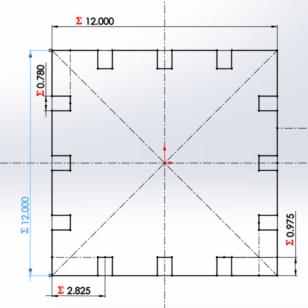
Only a few dimensions needed
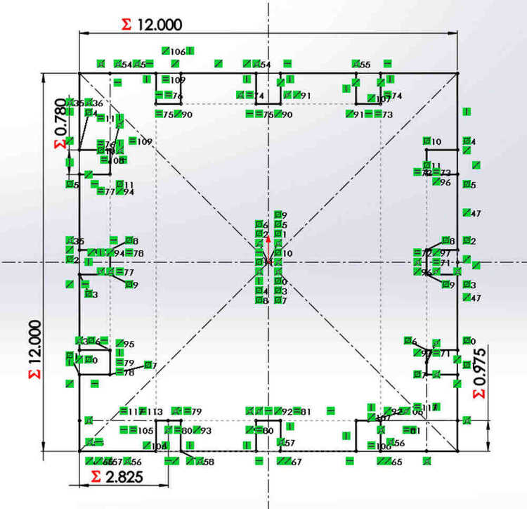
Notice all of the relations
Add the parts used to connect everything together:
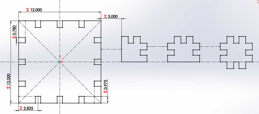
No dimensions this time
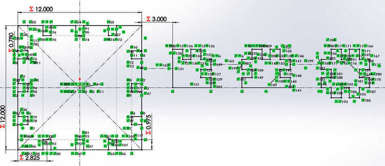
But a lot of relations
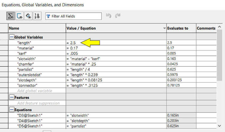
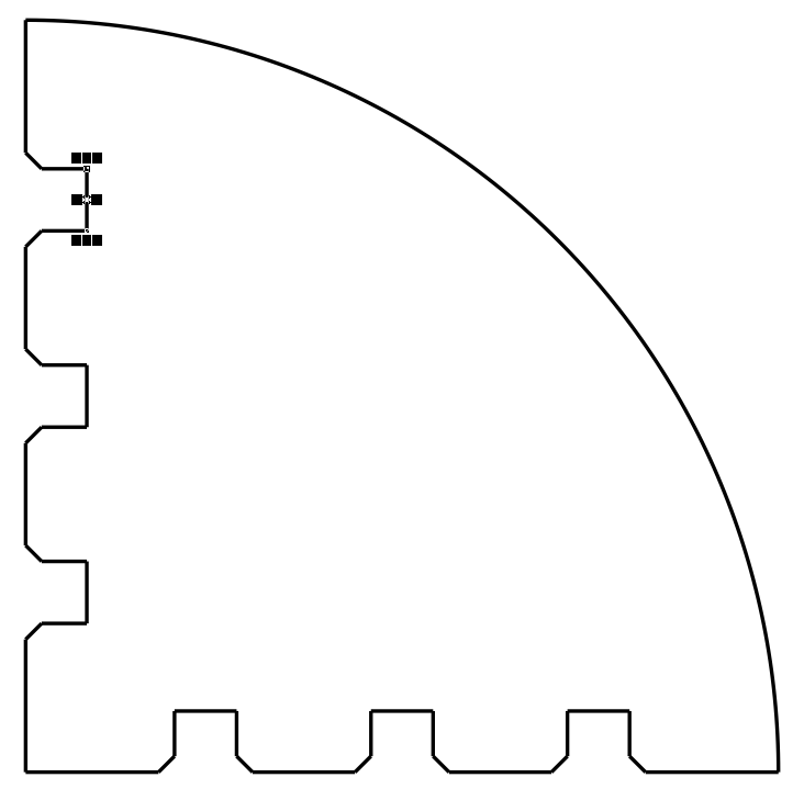
Now, add a quarter circle panel option:
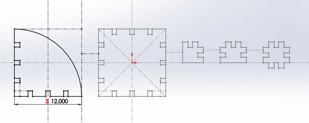
Only three variables can be changed directly; length, material, and kerf. The rest of the geometry are functions of the length.
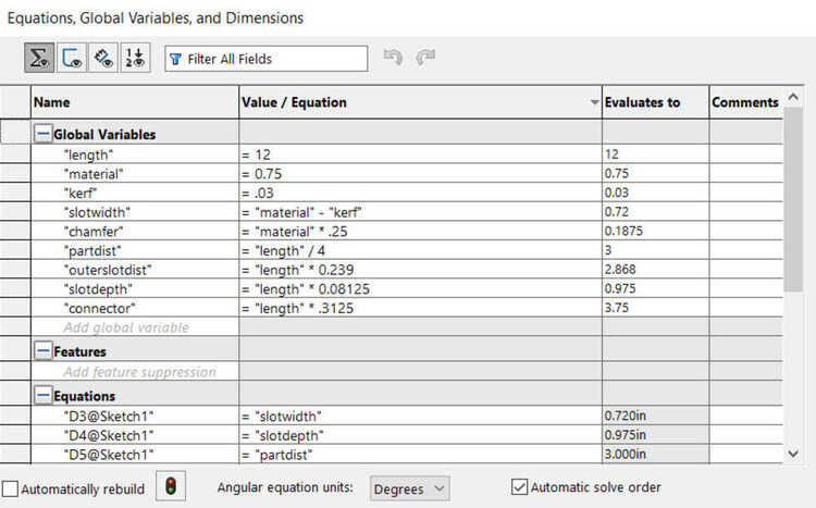
Chamfers are also parametric functions for the material thickness
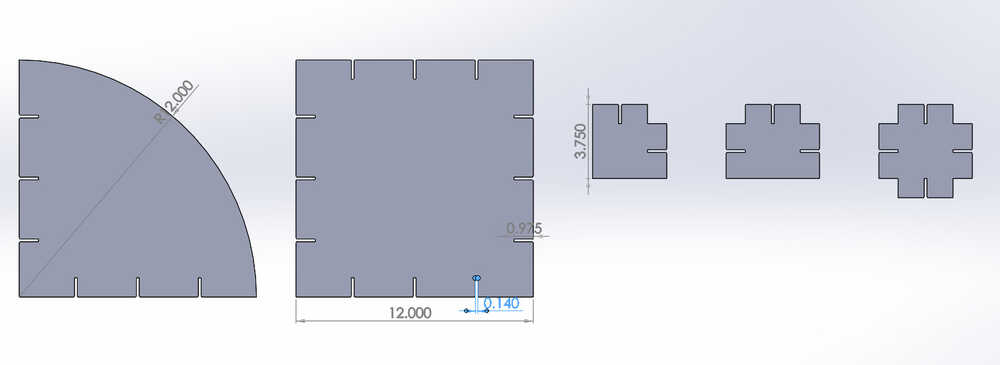
Evertying was drawn using full-sized dimensions with the intended material:
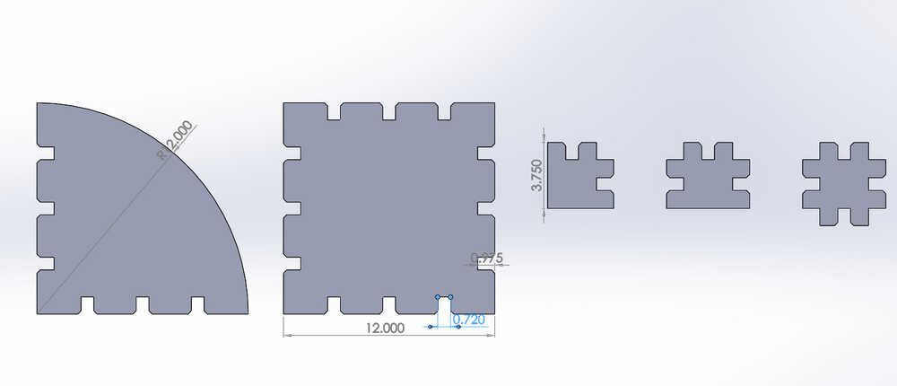
To prototype this using the laser, change material from thickness of plywood (0.75”) to the thickness of the cardboard (0.17”):
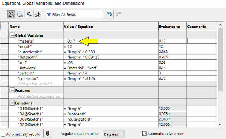
Rebuild the document. The slot width and chamfers have changed, but nothing else has:
Bring the main panel down to a more manageable size:
New dimensions of sides. Slot width remains the same. Slot depth has changed accordingly.
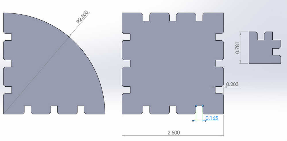
There are limits to length of sides and how it relates to the thickness of the material. Attempting to have 3” sides with 0.5” material would result in the slots interfering with each other.
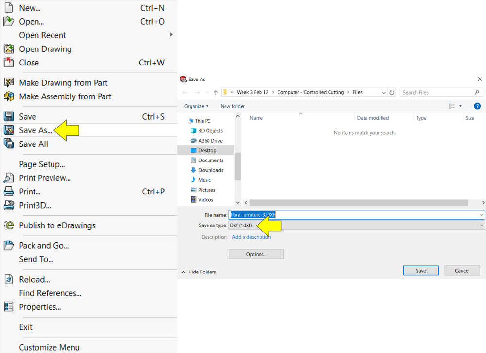
How to export DXF file for import into CorelDraw + pics
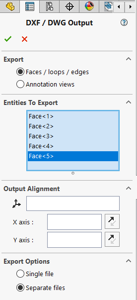
Save as, change file type to DXF
Change options to Faces/loops/edges, shift select all five pieces, change to multiple files
Clean up screen. Can remove unwanted geometries here if needed
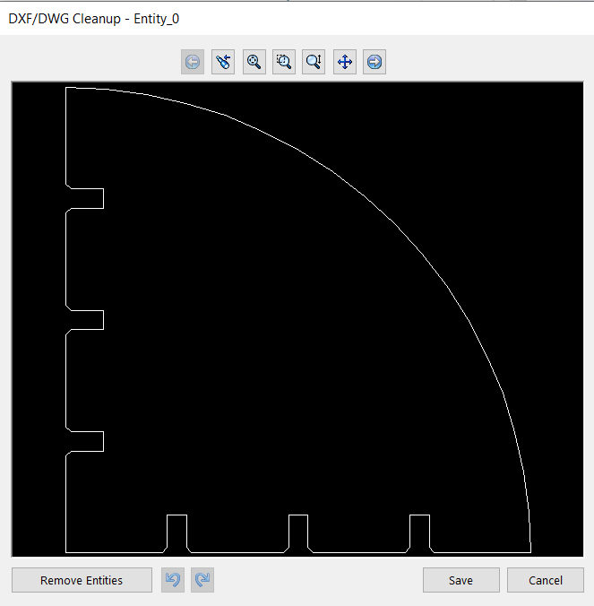
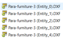
Software automatically names files
Importing into CorelDraw
Test cuts first, using parametrics for kerf adjustments.
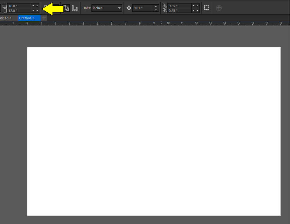
Starting off with an 18” x 12” piece of good cardboard
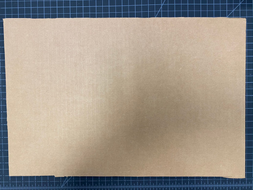
Set the material size/workspace in CorelDraw to match
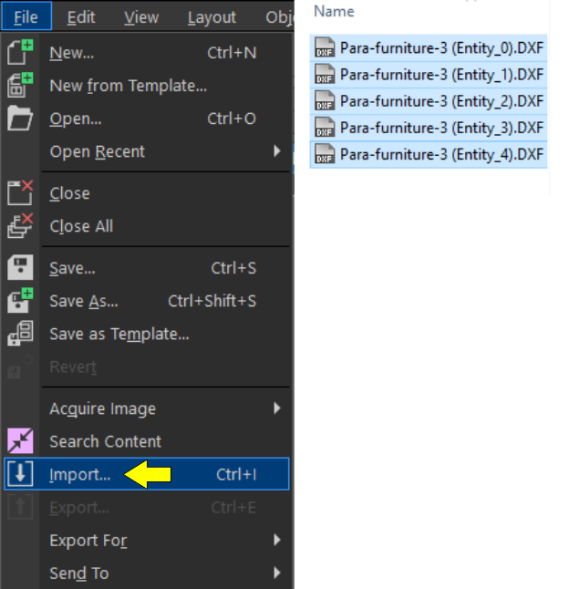
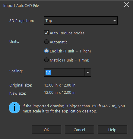
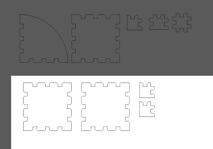
Import the dxf files created eariler. CorelDraw allows multiple dxf files to be imported at the same time, so I selected all five. When the ‘Import AutoCad File’ dialog box opens, make sure that the units for importing match that of the exported files.
Place them within the workspace by left-clicking.
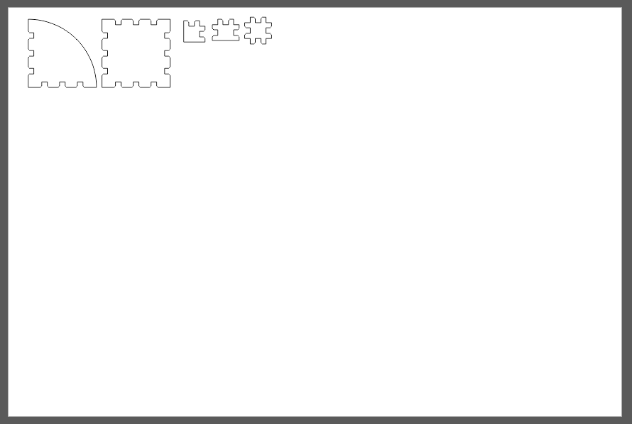
All five pieces on the workspace
When importing into CorelDraw, the line segments are not connected. If this is not connected, moving the geometry becomes tedious, and the laser software will not cut as one continuous line.
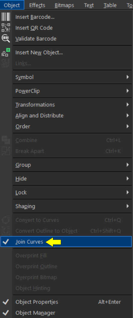
Connecting the segments, or joining curves as CorelDraw calls it, is an easy process. First, select all of the line segments/curves to be joined. Then drop down the object menu, and select ‘Join Curves’. After this all of the segments will be connected.
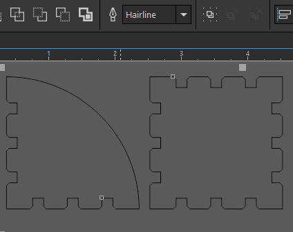
Now for our first test cut. In CorelDraw, only the geometry within the workspace will be cut. As seen below, I am only planning on cutting four pieces for the first test. The others I moved out of the workspace.
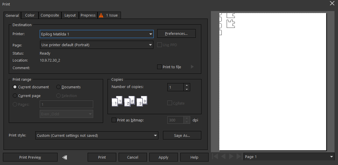
Next is sending to the laser. Using Ctrl+P or selecting print from the file menu brings up the print dialog box. I selected the laser, in this case Epilog Matilda. Something to note is the print preview one the right side of the dialog box. You’ll notice that it does not look correct. The geometry is off the side of the page. We’ll fix by selecting the Preferences button next to the printer drop down box.
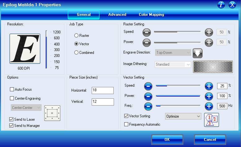
This brings up the print driver in which the setting for the laser are changed. The process of this is outline on the group site, but here’s a brief overview. The job type is vector, so it’ll only cut, not engrave. To correct the print preview, change the piece size to match the size entered into CorelDraw eariler. The settings for speed, power, and frequency are also entered here. These are the setting that were determined during the group assignment
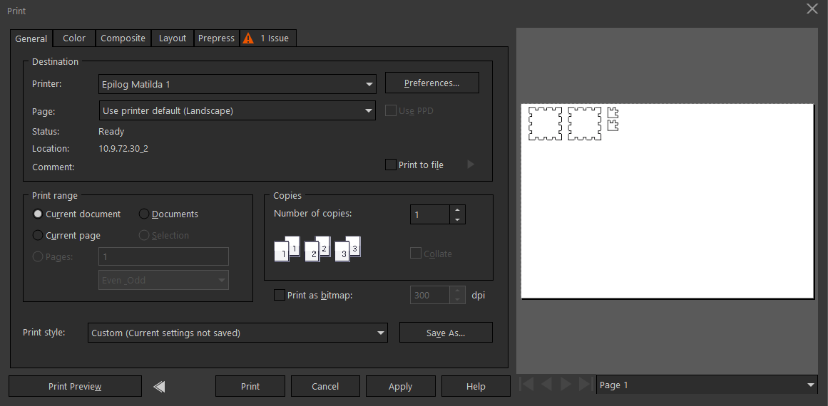
Now the print preview looks correct. Select print and the file will be sent to the laser.
The Kit
Inserting the material, focusing, and running the file are shown in the group assignment, so here you can see the end result of the cutting process
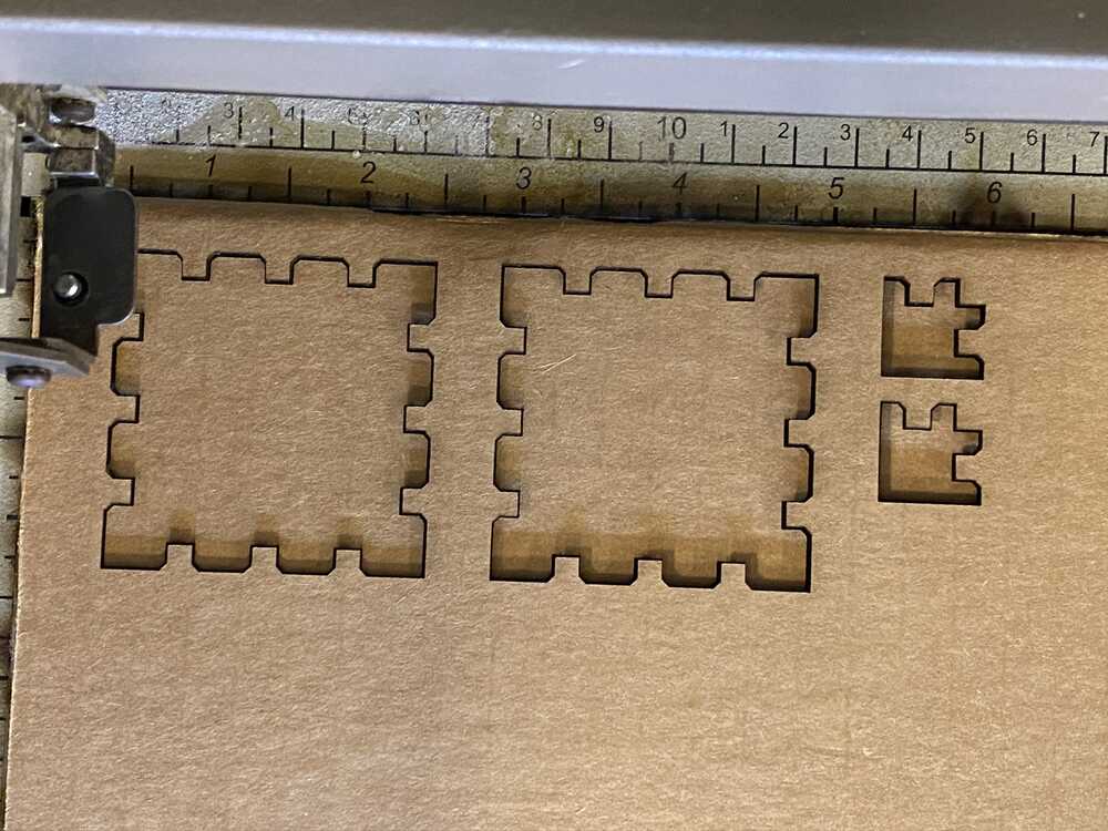
As the kerf had been determined earlier, the fit worked the first time. The next two pictures show how the fit works. It presses together without binding or falling apart. Also, there is no interference from the perpendicular pieces
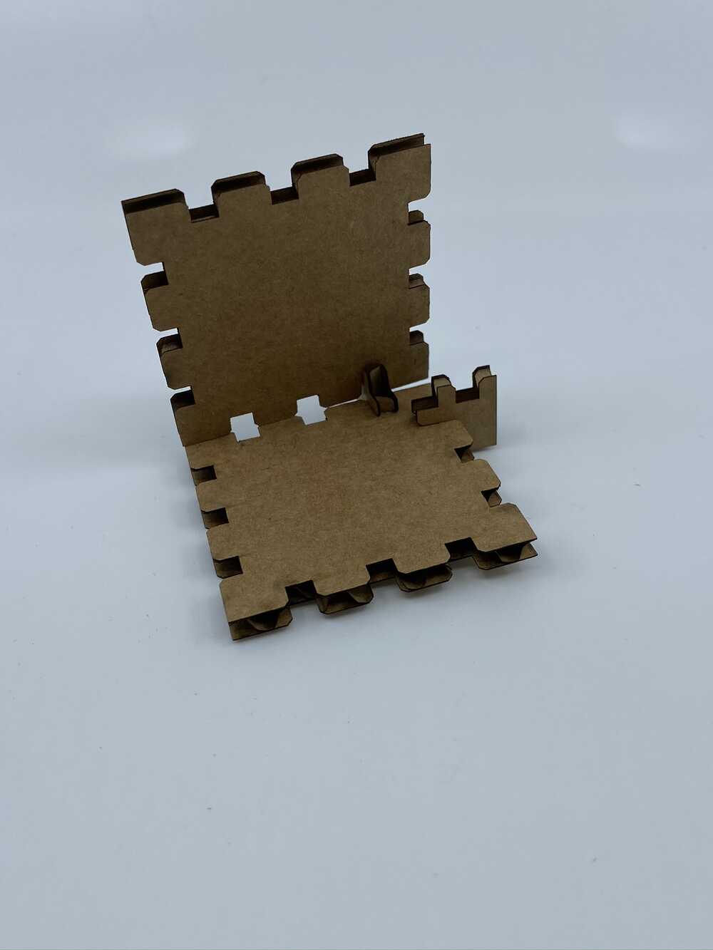
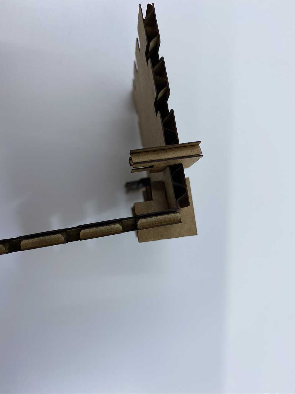
Just right
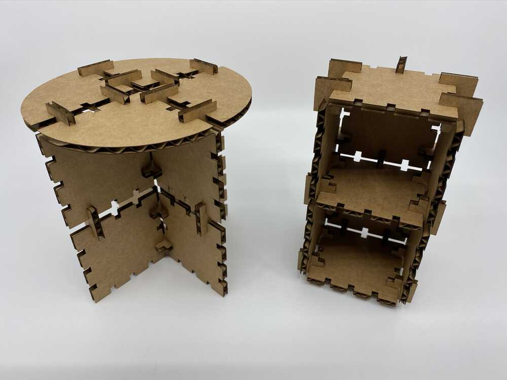
Kit Configurations
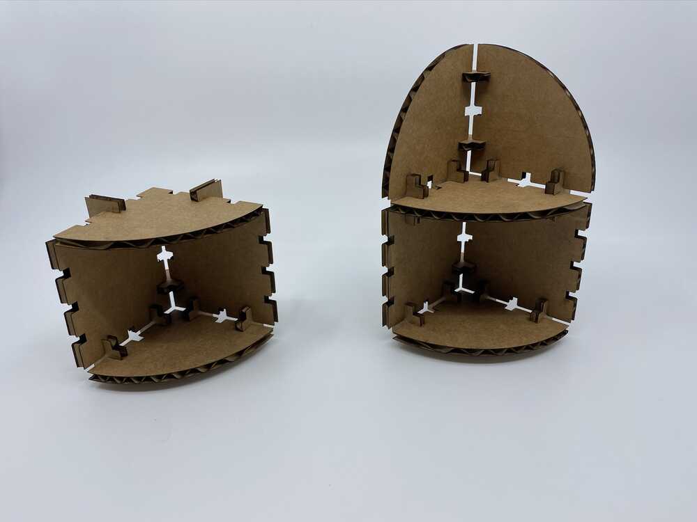
Small corner table and shelves
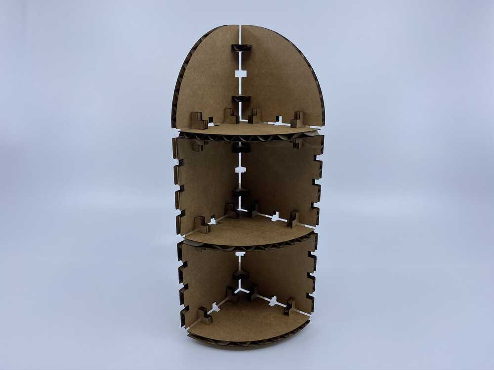
Large corner shelves
Small table and a modular cube shelf
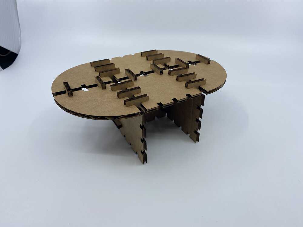
Large table
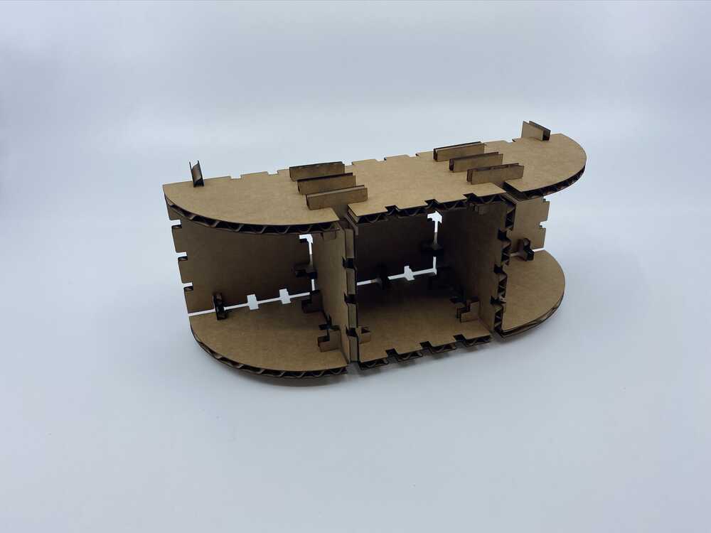
Television/entertainment stand
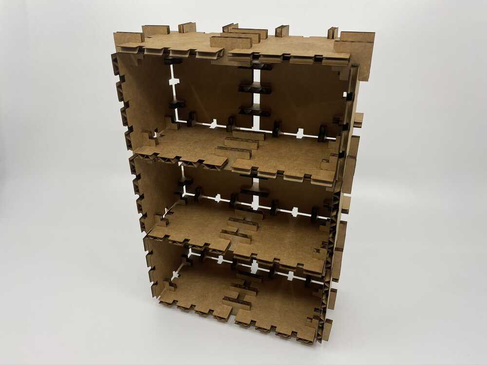
Large bookcase
The various shelving units
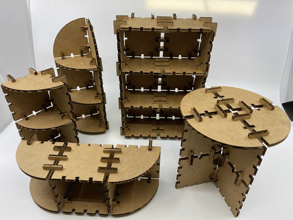
The whole living room set
Vinyl
I started with Roland Cutstudio, the software provided by the vinyl cutter manufacturer.

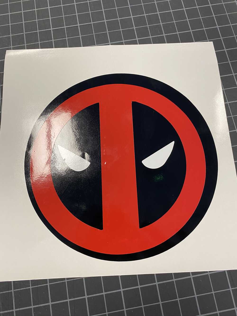
I searched online for a decal I wanted to make, in this case, the Deadpool logo. Right-click the image and select copy, and paste it directly into Cutstudio.
The Deadpool logo is a registered trademark of Marvel Characters INC. The logo used here is an artist derivation and is used for non-commercial and educational purposes only
- Deadpool logo
Link to artists’ page
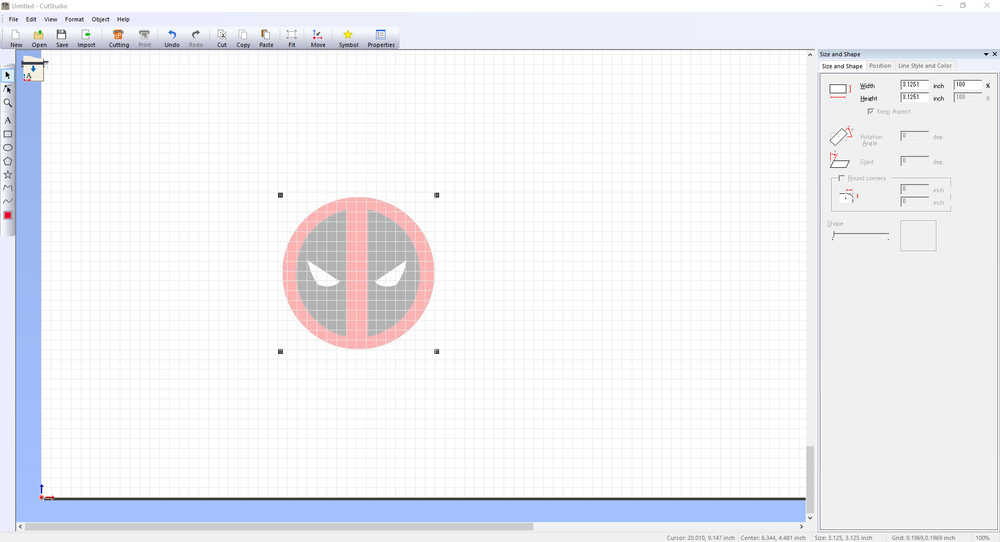
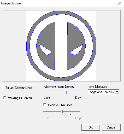
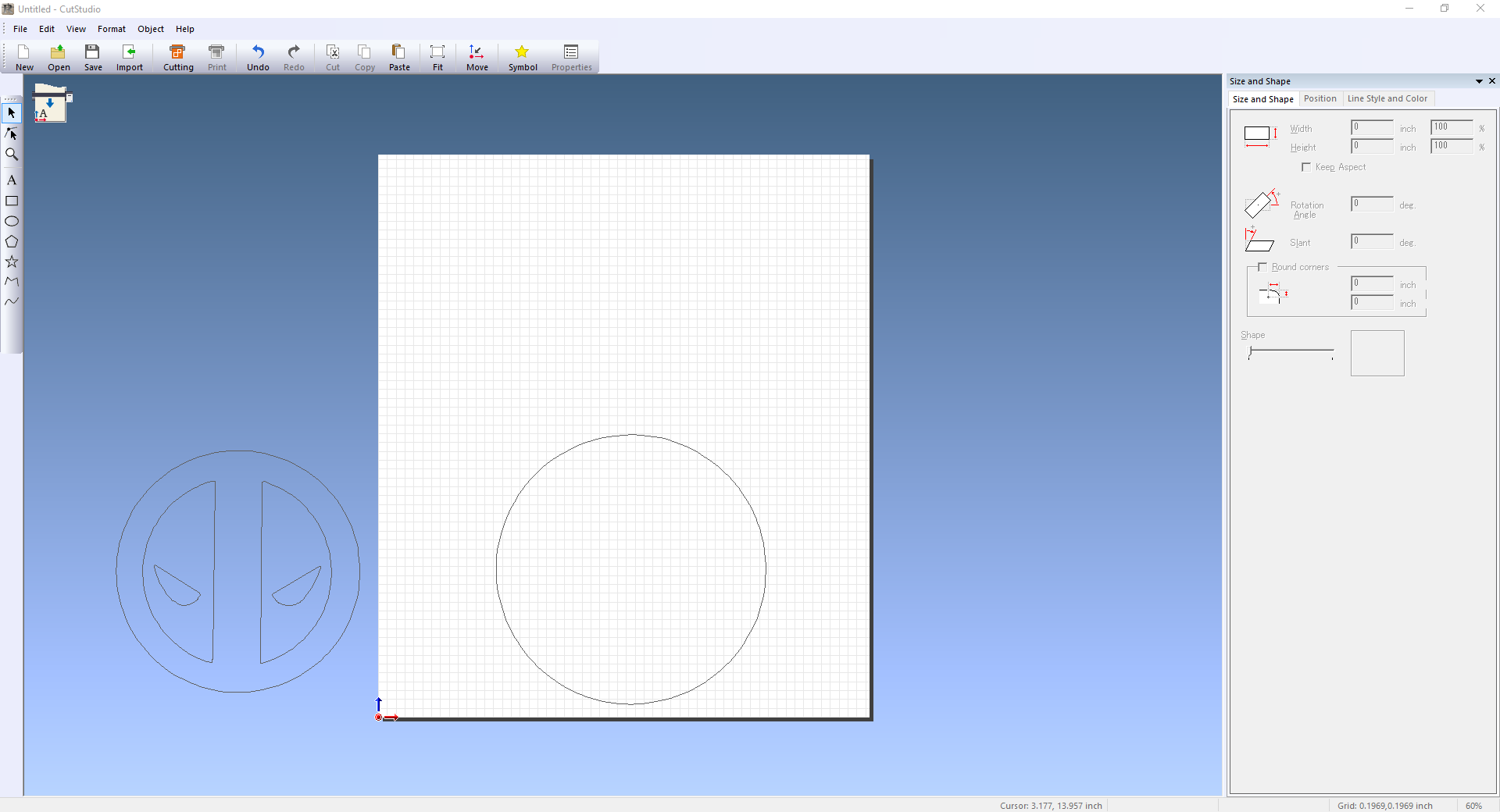
This image is just a bitmap, only pixels, no lines to cut. To create those lines, select object, then image outline
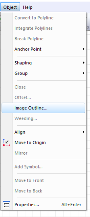
This dialog box allow for the extraction of contour lines. It works by placing lines between the separation of colors. Each color will have it’s own set of lines
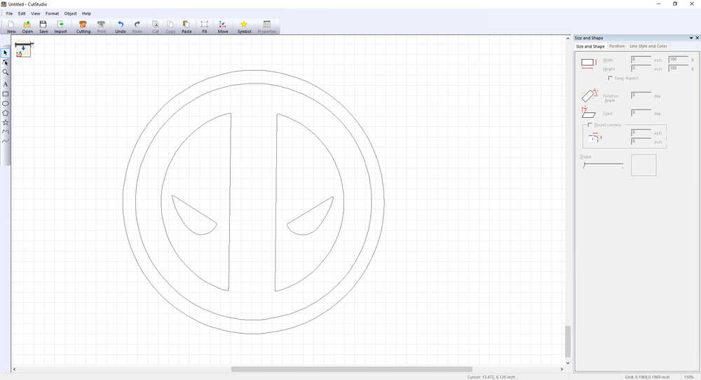
Here is the bitmap that is now just polylines
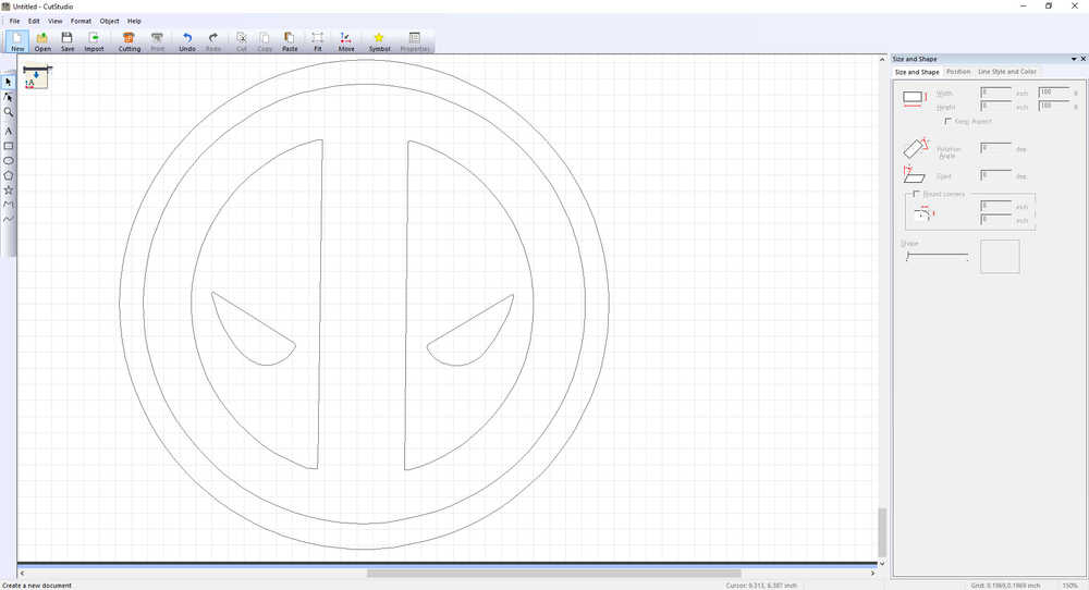
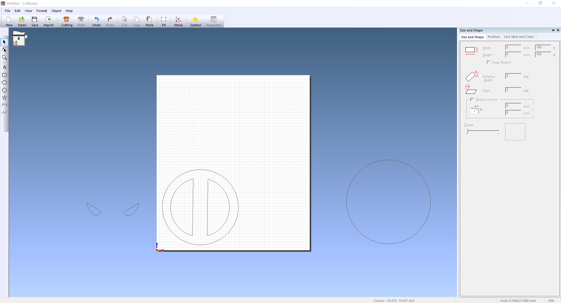
I wanted a larger size, so by right clicking the image and selecting properties, the properties window pops up. This allows for changing the size and shape of the image.
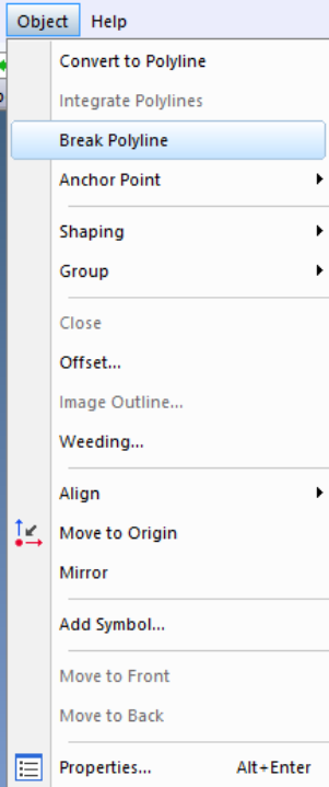
The image is still one object, it needs to be broken down into the individual colors. Do this by selecting object, then break polyline. Now the geometries are separate objects.
Before moving on, the size of the vinyl has to be determined. Due to the way the vinyl cutter secures the vinyl, the actual usable space is small than the true physical dimensions of the vinyl
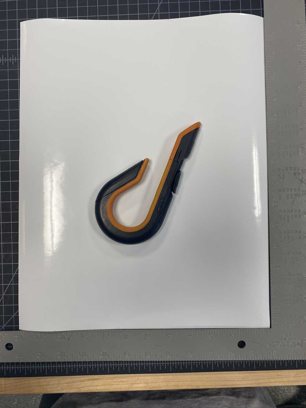
A piece that will be cut
The piece to be cut needs to be loaded into the cutter. Below is the control interface that we’ll be using
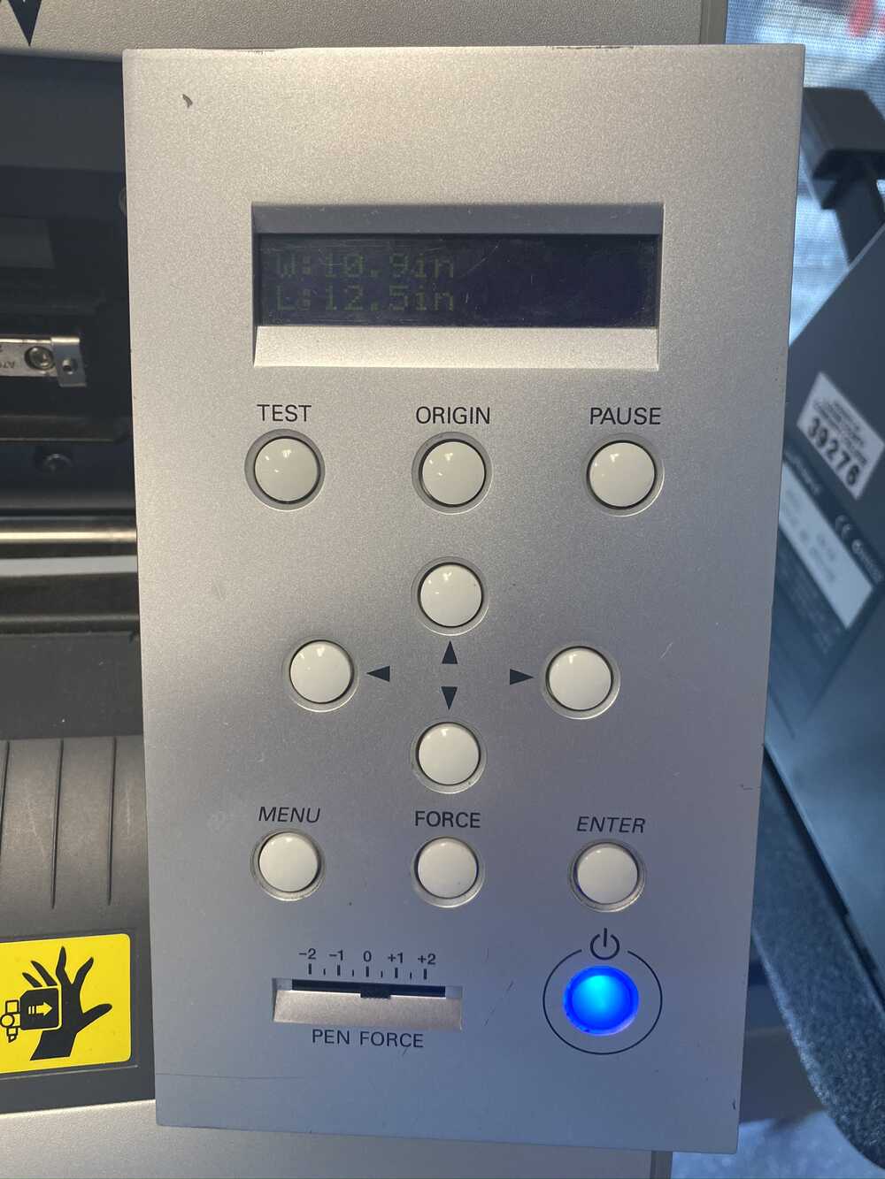
The GX-24 controls
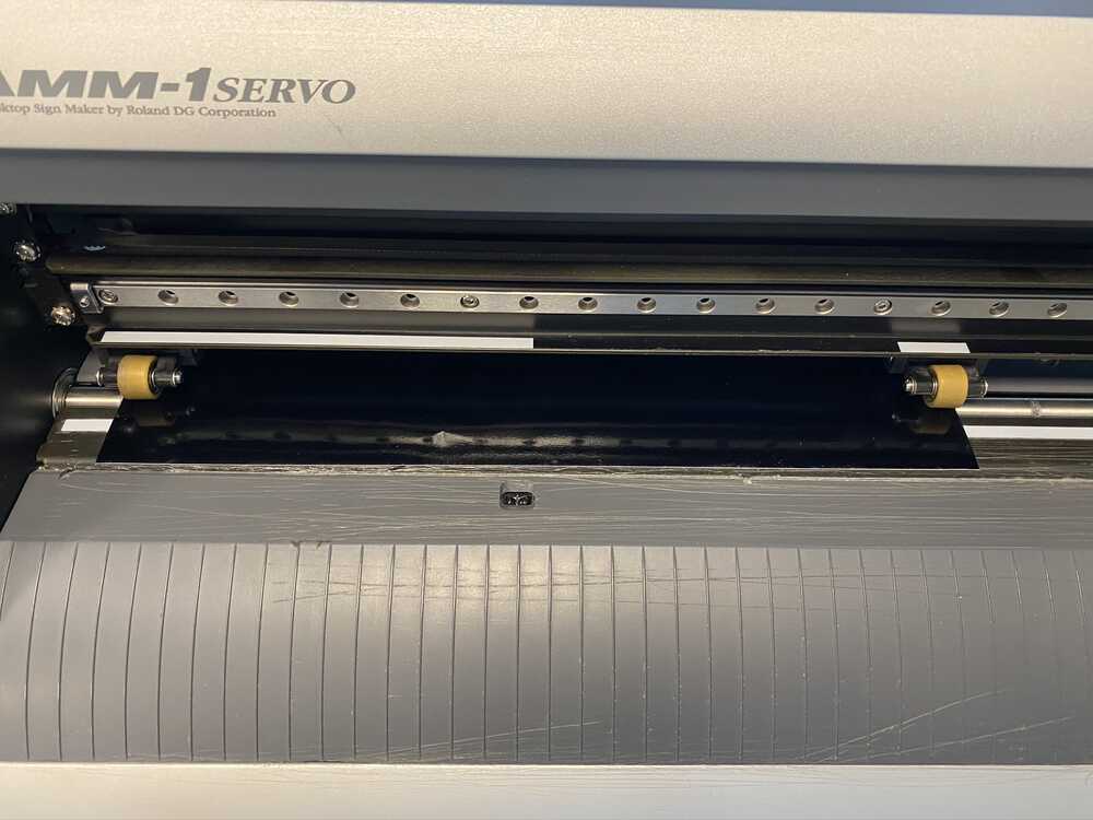
To load the vinyl, slide the piece under the rollers. The rollers need to be placed under the white blocks and the light sensor needs to be covered. The rollers should also be as wide as possible as the cutter only ‘sees’ what’s between them
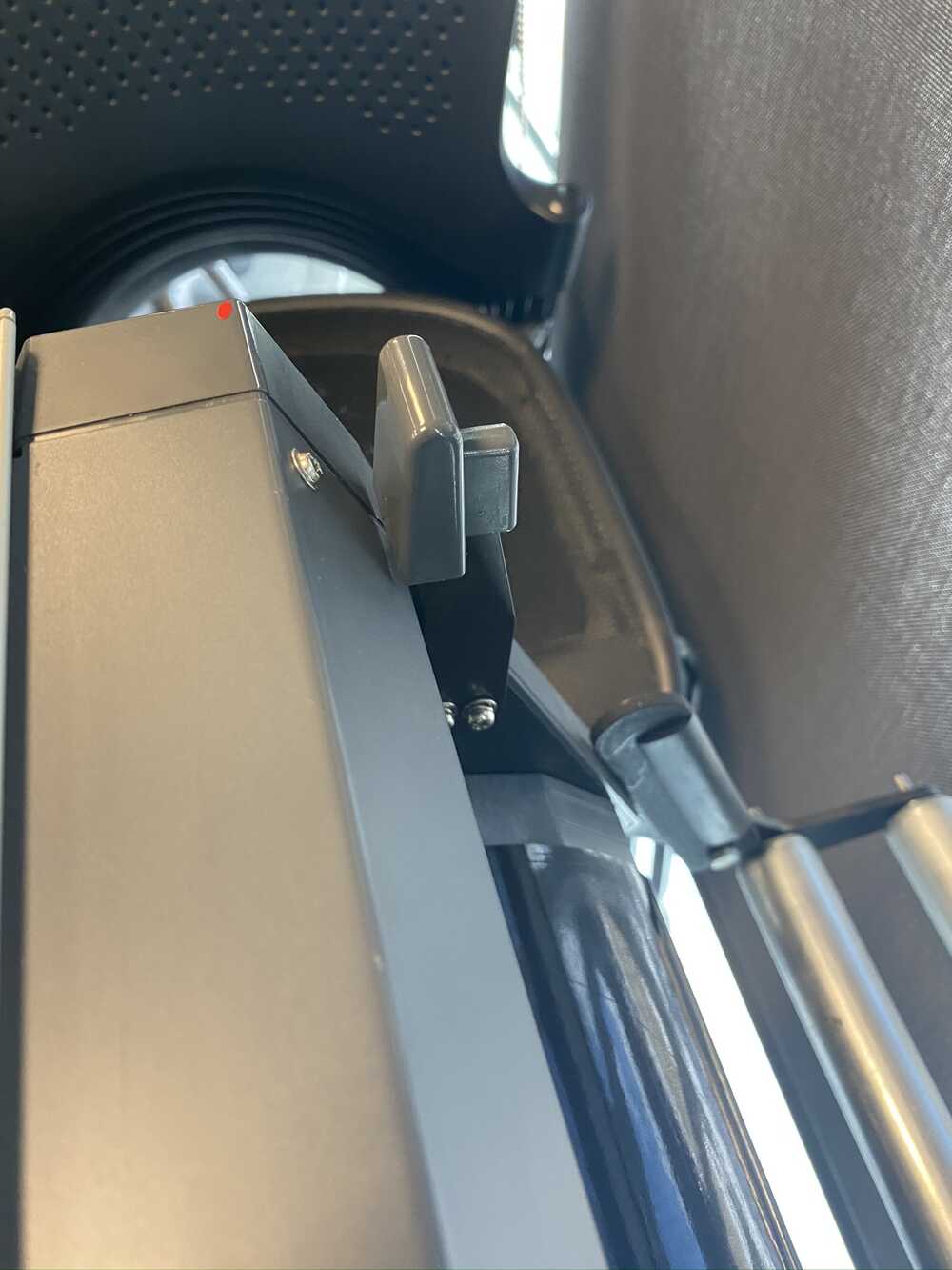
Once everything is in position, lock the vinyl in place with the lever on the back left of the machine. Going back to the control pad, press the down arrow until the screen reads ‘Piece’ and press enter. The machine will more the cutting carriage into place and measure the usable cutting area. That cutting area will be used in the setup of the vinyl cutter’s properties.
The cutting area size has to match the material being used. This is done by selecting file, and cutting setup
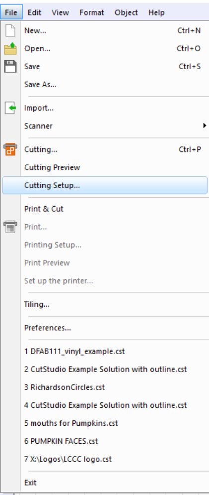
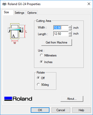
The cut setting dialog box will open. Select the Roland GX-24 and clicking property will open the settings options for the vinyl cutter
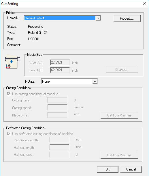
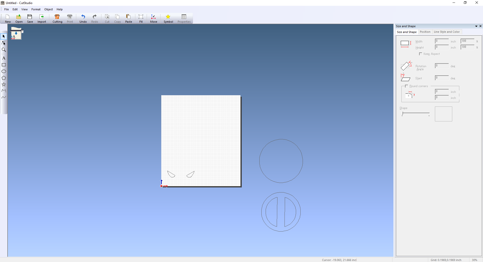
Enter the dimensions from the vinyl cutter’s display. Once this is completed, the workspace will change size to match the entered dimensions
I started with the black background. I moved the objects I didn’t want cut off of the cutting area.
Once that was done, the cutting dialog can be opened with CTRL+p. The vinyl cutter will start cutting as soon as the file is sent. Once it’s done, go back to the control pad and press the menu button. The screen will display ‘unsetup’. Press the enter key. This will move the carriage back to its home position. Unlock the vinyl and remove.
Repeat these steps for all of the different colors
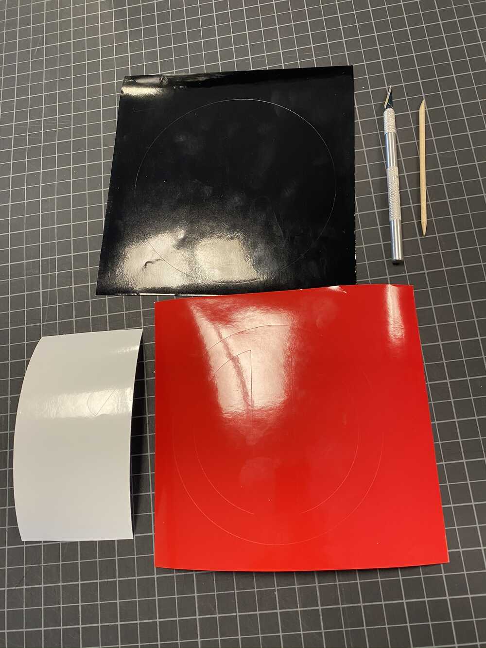
The red
The white
Weeding and application
Once the pieces are cut, the end result is as shown. The unwanted vinyl has to be removed to expose the cut shapes in a process called weeding
As seen below, the pieces are starting to emerge as the unwanted material is weeded out
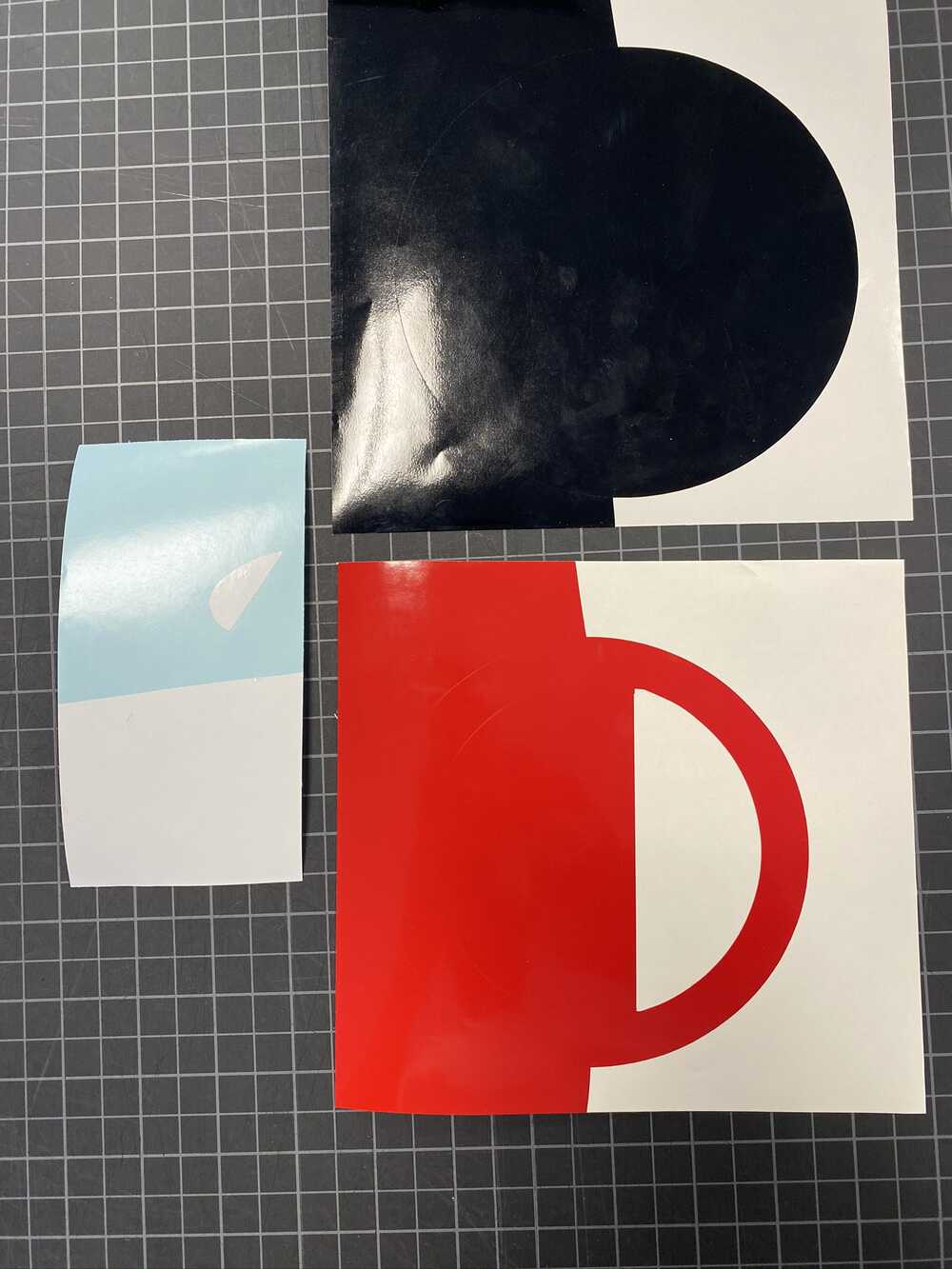
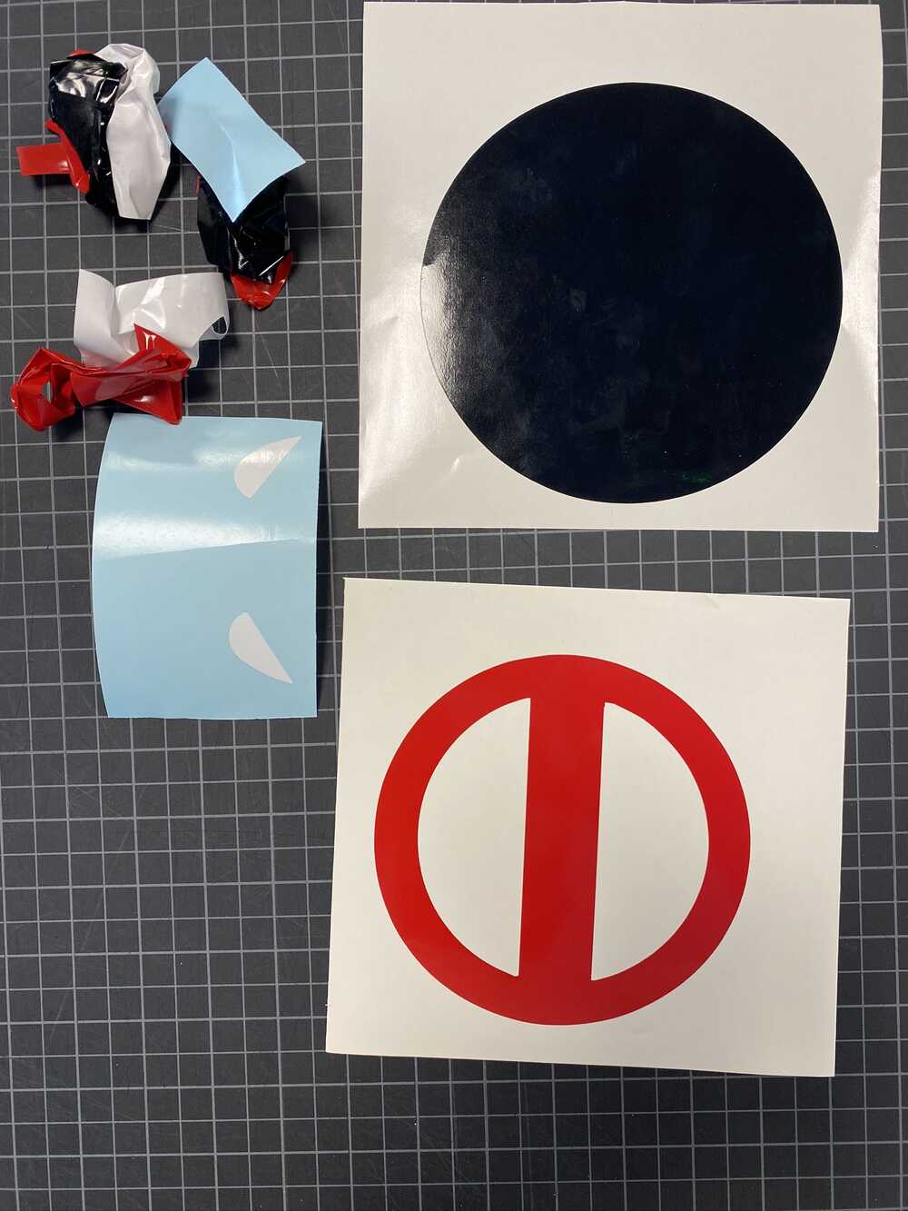
The various colors need to be layered. This process is made much easier using transfer tape. Transfer tape removes the vinyl from the wax backing, but then removes easily once the vinyl is applied. Because the black piece is the base layer, it does not need transfer tape. The other two colors do, however.
![]()
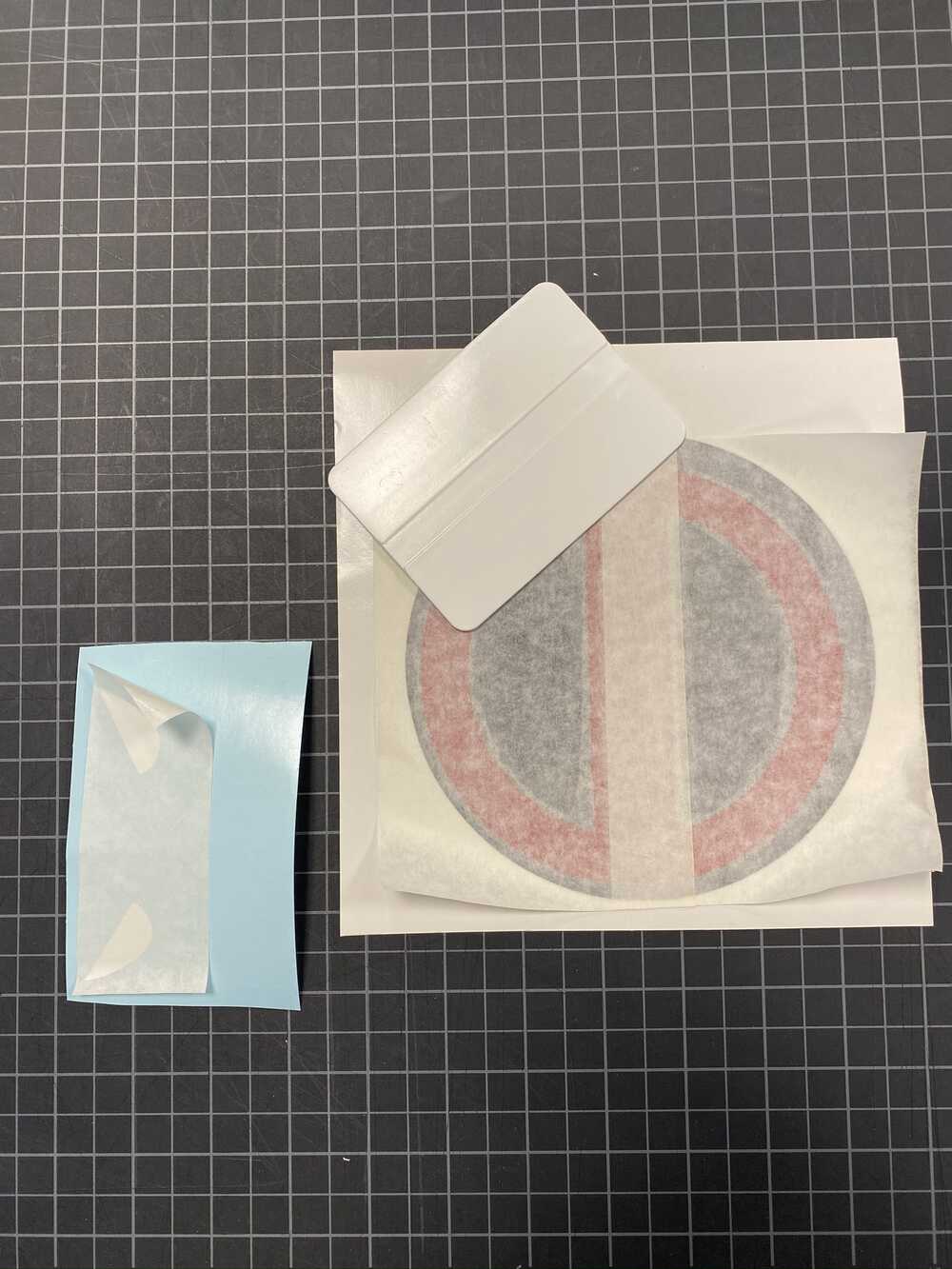
I applied the red layer first. Using a plastic burnishing tool helps with working out the air bubbles
Once applied, remove the transfer tape
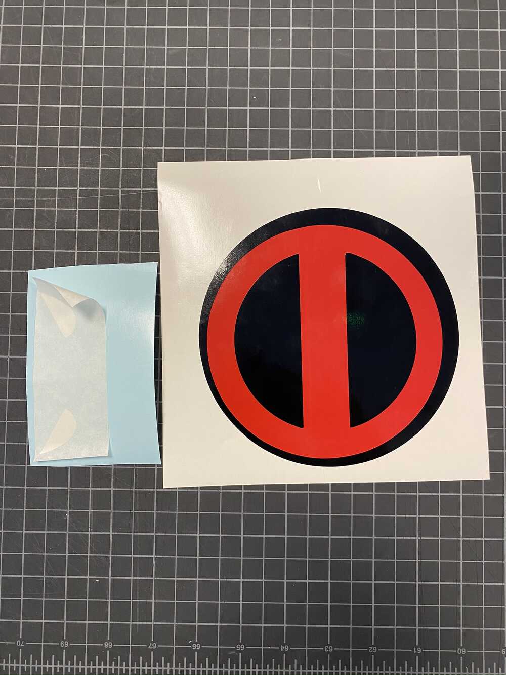
A little out of alignment, I hope Deadpool doesn’t mind
Repeat with the white vinyl
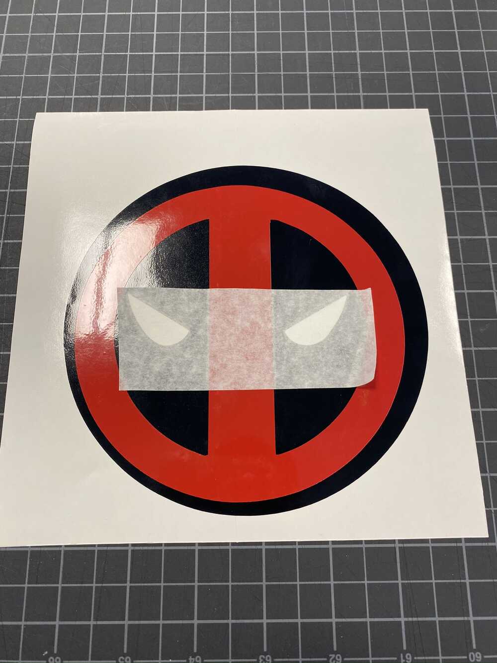
Remove the transfer tape and the job is complete
The files

This work is licensed under a Creative Commons Attribution-NonCommercial-ShareAlike 4.0 International License.