8. Computer controlled machining
This week was dedicated to learning the CNC machining process and to “build something big”
Design (something big)
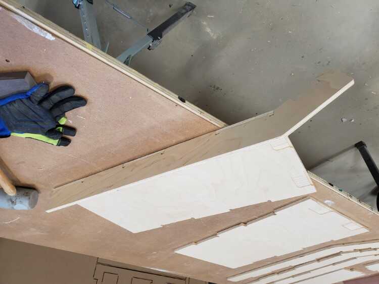
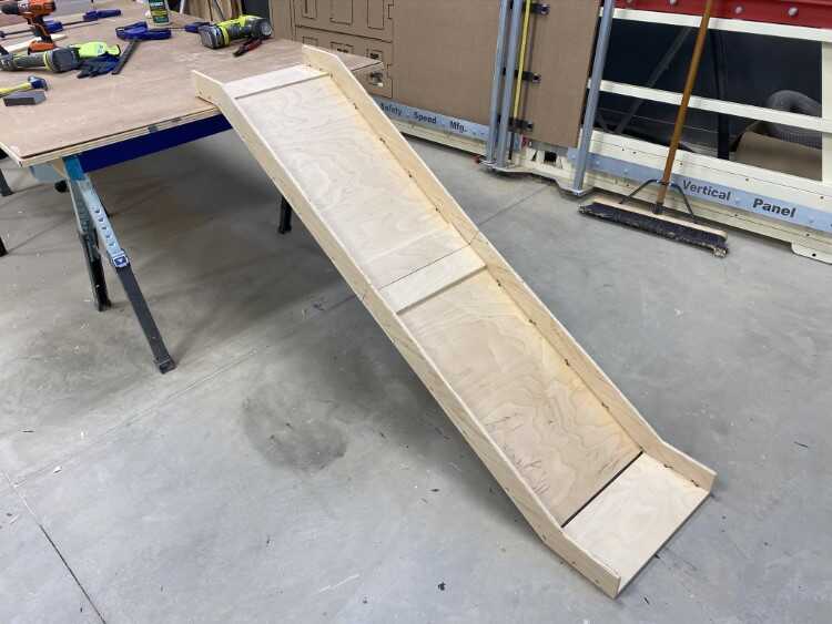
I have three very large dogs. Getting into and out of my vehicle can be difficult for them. I decided to design and build a folding ramp to make that process easier for my dogs.
As with everything I do, I started with a hand drawn sketch. I knew the height of the opening for my vehicle and roughly the angle I wanted. A little trig and I figured out the best length for the ramp deck.
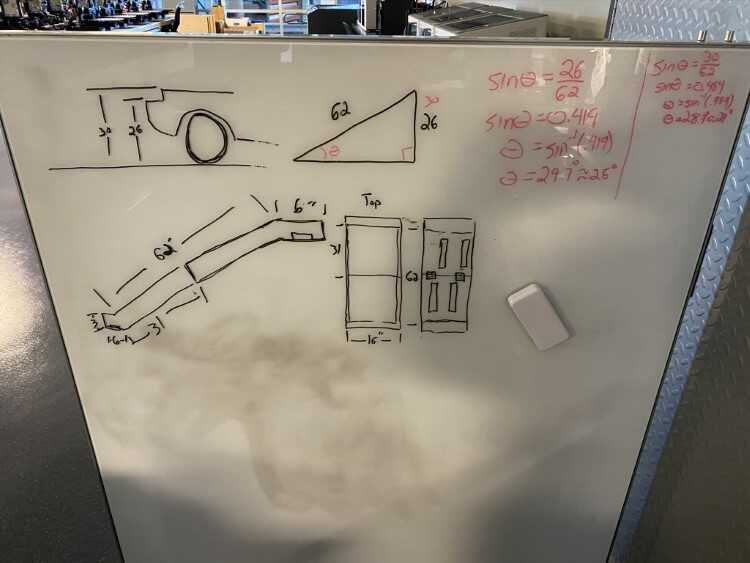
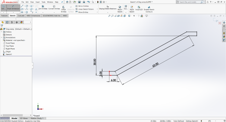
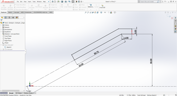
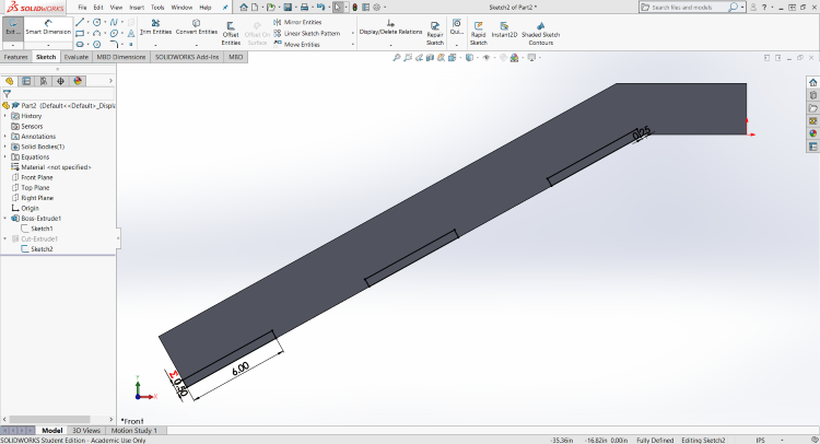
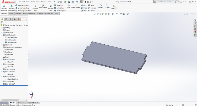
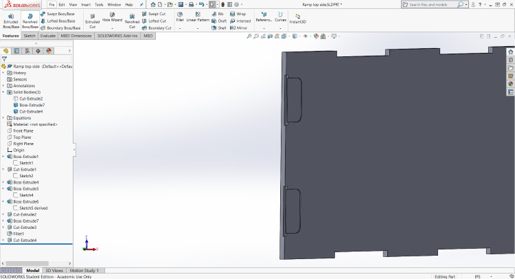
Using SolidWorks, the first step was to design rough idea of the side profile based on the math and dimensions from the hand sketch
Next was to export a dxf file, import it into Corel, isolate top ledge, laser cut from cardboard, and perform a clearance test fit This process was learned during the Computer controlled cutting assignment.
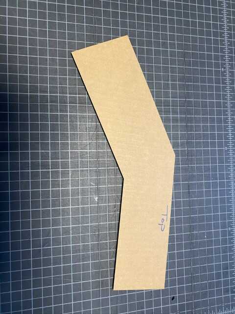
Cardboard mock-up
![]()
Rests on ledge and clears rear bumper
The material being used is going to be 0.5” beech plywood, so slots and tabs will be designed with that in mind. I decided to make the material thickness value parametric, as most plywood dimensions are nominal and might not be exactly 0.5” thick.
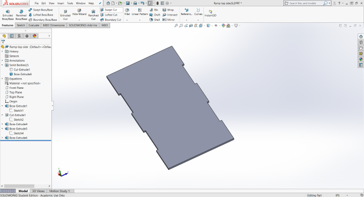
Being two separate pieces, I decided to design the top half first, starting with the profile
Next was to make slots for the ramp surface to interface with
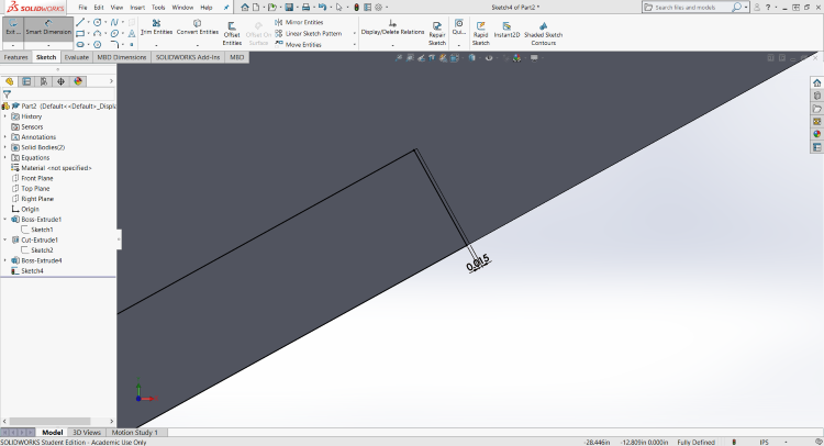
Added tabs with 0.015 clearance for press fit. Clearance value is based on group experiments and is also parametric
PIC SW ramp base tabs
Top side surface with tabs and slots
Next, a slot was needed for the top ledge
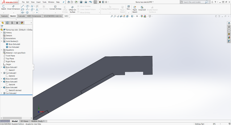
Then design the top ledge with tabs that set to the same clearance values
The next step was to incorporate slots for the hinges to flush mount into
First, the hinge dimensions had to me taken PICS Hinge measurements
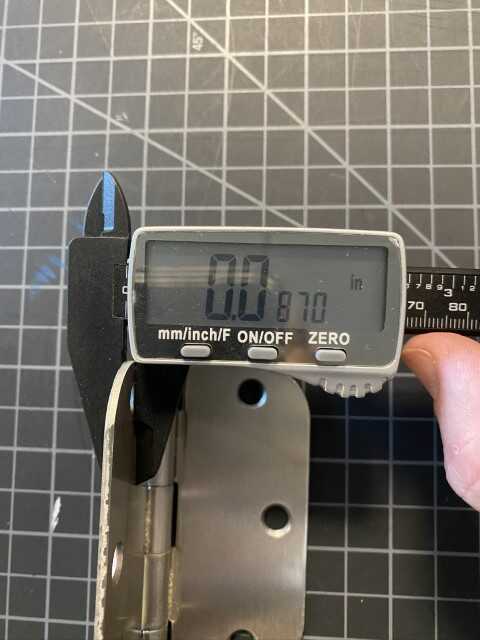
Thickness of hinge to know the depth needed for recess
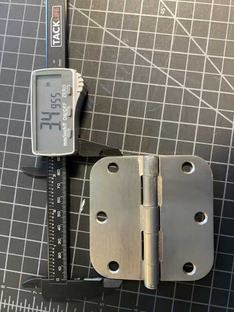
Hinge width
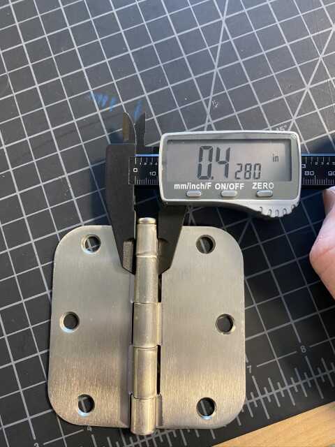
Width of barrel to add extra depth to recess for flush mount
With those measurements, the recess slots for the hinges were added
The same process was repeated for the lower portion of the ramp.
I wanted to check the actual thickness of the material I was using before it was cut.
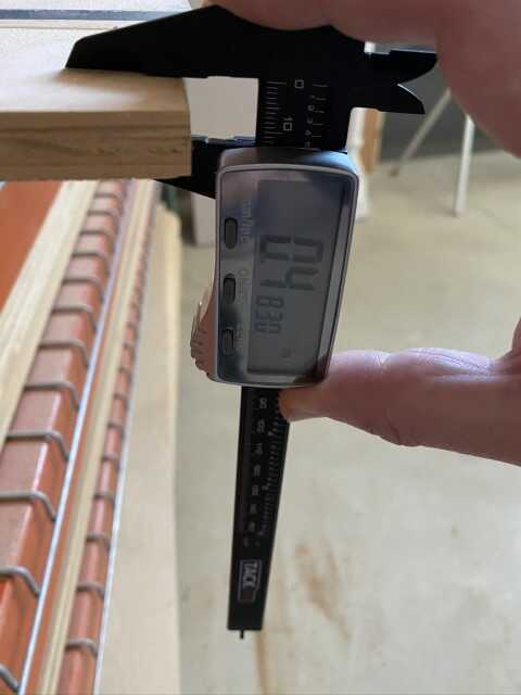
The material was slightly thinner than 0.5” Because the thickness value is parametric, it can easily be adjusted
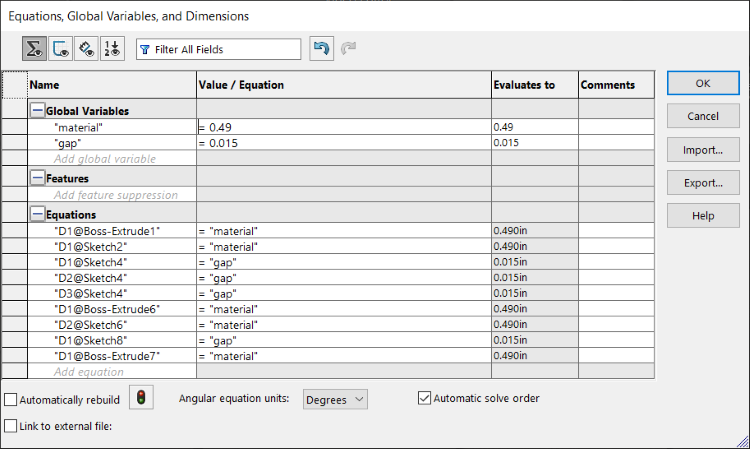
Select Manage equations from the left workflow tree
PICS SW-manage equations
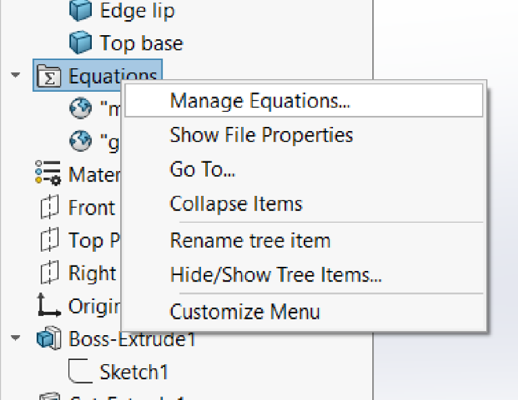
This opens the equations sheet
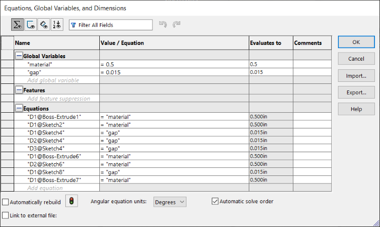
The material value was set to 0.5”.
Change to 0.49. Doesn’t seem like a lot, but even 0.01” can make a difference when press fitting
Export DXF files like before so the CAM toolpaths can be generated.
CAM toolpathing
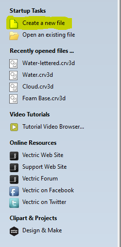
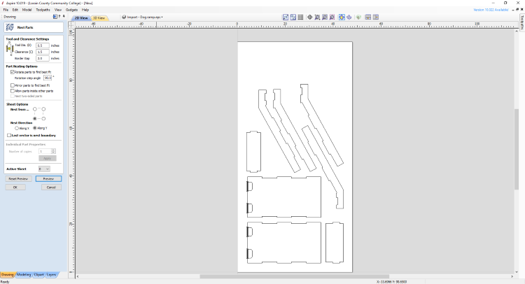
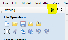
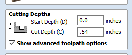
Vectic Aspire was used to generate the CAM toolpaths for the CNC router First, a new file needs to be created
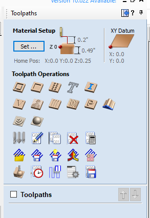
Set size to match material: 48” x 96” x 0.49”. Be sure that the “use offset” option is turned off and make note of the XY datum position
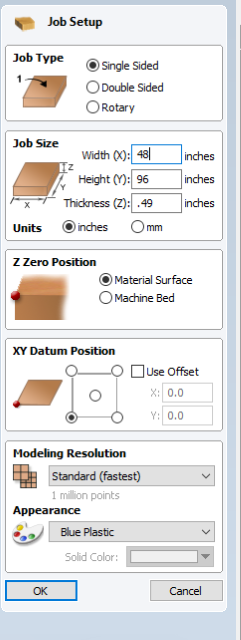
Aspire now provides a WYSIWYG window
![]()
With the material properly set up, the DXF vector files need to be imported. Under file, select Import and then Import Vectors…
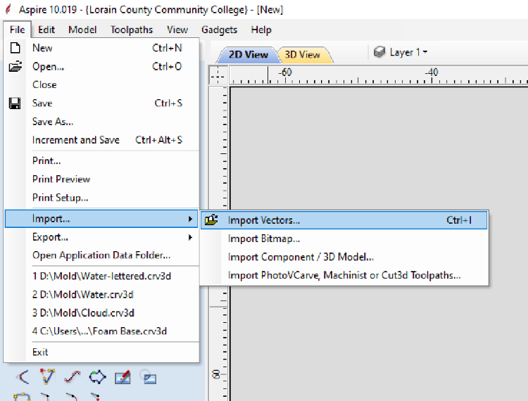
CTRL+I can also be used
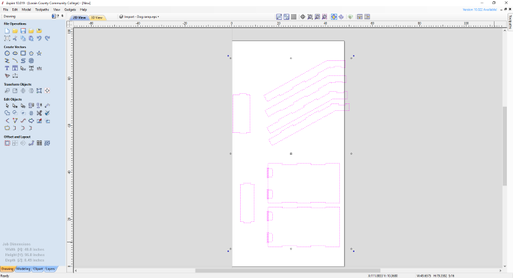
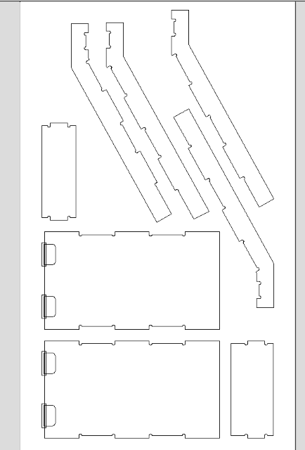
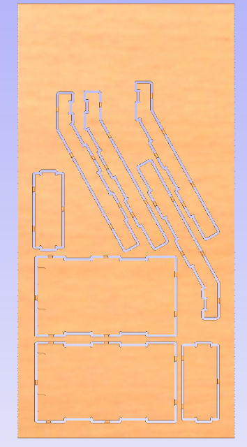
Imported vectors of the parts to be cut
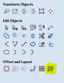
A handy feature of Aspire is that it can auto-nest the vectors to optimize material usage. With all vectors highlighted, select the nest tool under Offset and Layout
PIC Aspire-nest tool
Opens the nest parts window where the settings are chosen. The tool being used is a 0.5” end-mill. Clearance is the gap between the parts, plus the diameter of the tool. Border gap is how from the edge of the material the parts will be nested. The angle of rotation the algorithm with use to find the best option can be set. The y-axis of our CNC router is the long axis, so that is set as the nest direction.
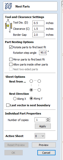
Select preview
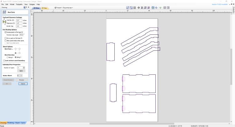
Aspire-nest after
This saves a lot of time
Settings can be adjusted and previewed again. Once a satisfactory next is generated, select OK to confirm
T-bones need to be added to the inside corners of the slots and tabs to allow clearance for the square edges of the plywood. To perform this task, select the fillet tool from the Edit Objects window
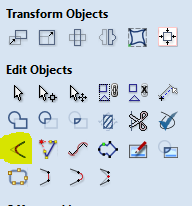
This opens the create fillet window, select T-bone fillet
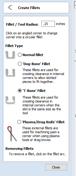
Make sure to set proper tool radius, 0.25”
Select inside corners of vectors to create T-bone fillets. These will give clearance for square material, compensating for the round profile of the end-mill
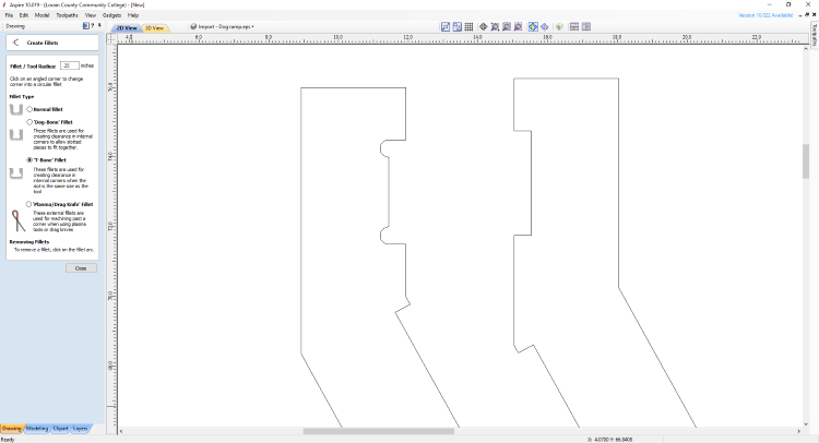
Work around all inside corners. Always double check that none were missed.
Always go around and double check that all of the inside corners have T-bones.
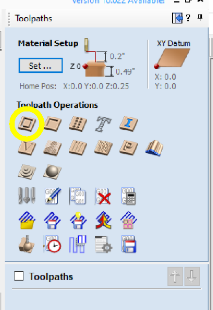
Now to add the toolpaths. Select switch to toolpath commands
This opens toolpath tool window
The first toolpath will be a pocket for the hinges. Select the pocket tool
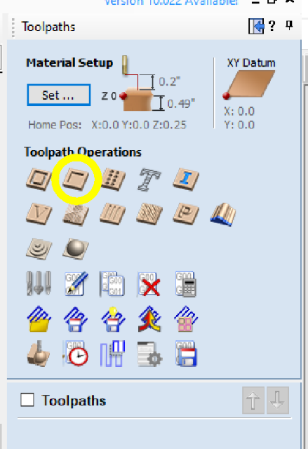
This opens the pocket tool window
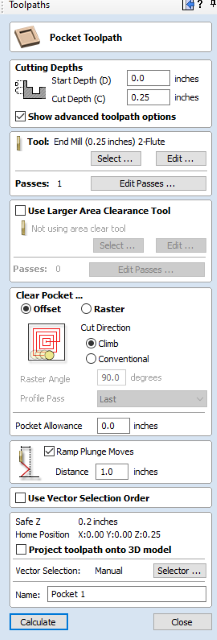
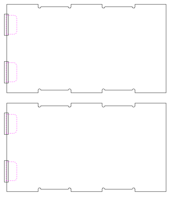
Chose the vectors to be pocketed. Here, just the hinge pocket vectors are highlighted in pink
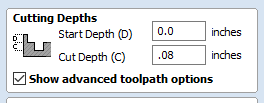
Set the cut-depth to the thickness of the hinge 0.08”
Next, set the proper tool
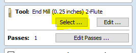
Open tool selection window. Settings for RPM, feedrate, cut-depth, etc can be set here
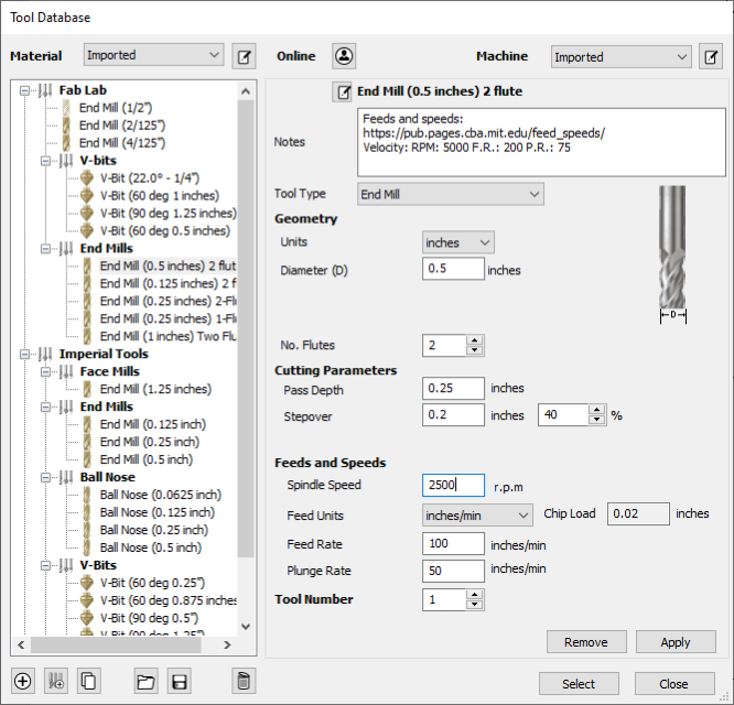
Select the 0.5” 2-flute end-mill. Settings were found and calculated from the following website:
Because plywood is being used, the OSB settings were used as those were the closest. Due to experience with the machine a slower feed rate was used for pocketing, but the RPM was adjusted to maintain chip load.
To calculate the needed RPM, i used the following formula:
- RPM = 4 * CS/D
-
CS = surface speeds
-
D = Diameter of tool
The feed rate is calculated with the following formula:
- FR = n * CPT * RPM
-
n = number of flutes
-
CPT = chip load
Referring to the calculator, I determined the surface speed to be 650 ft/min and the chip load to be 0.022”
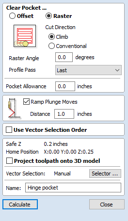
The rest of the settings are shown here. Under clear pocket, there is Offset and Raster. Offset moves in a circular manner, starting from the inside, while vector moves in a straight line at a defined angle. Raster was chosen here. The profile pass was set to last for a better finish. Ramping plunge moves is selected due the tool being used. It is not a center-cutting tool, so it is not designed to plunge straight down into the material. The Ramp plunge moves the tool into the material at an angle so the cutting edge is used.
| Thru-cut | ||
|---|---|---|
| Tool Diameter | 0.5” | 0.5” |
| Surface Speed | 650ft/min | 650ft/min |
| Chip Load | 0.022” | 0.022” |
| RPM | 2500 | 5000 |
| Feed rate | 100in/min | 200in/min |
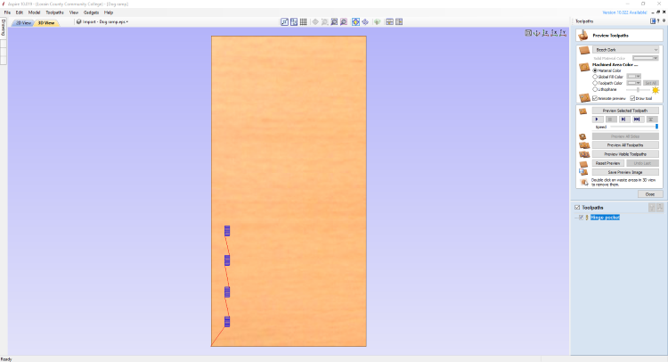
Select calculate. Will generate a simulated preview of the toolpath
Select preview all toolpaths to see the it simulated
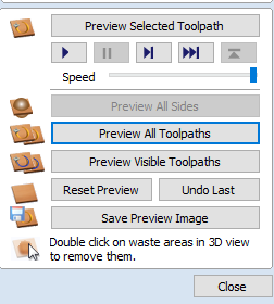
This gives a visual simulation showing how the cuts will look.
Same process is used for the hinge barrel relief pocket.
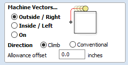
The Profile tool is used for cutting through material. Select the profile toolpath tool
Select all the vectors to be cut. They will be highlighted in pink
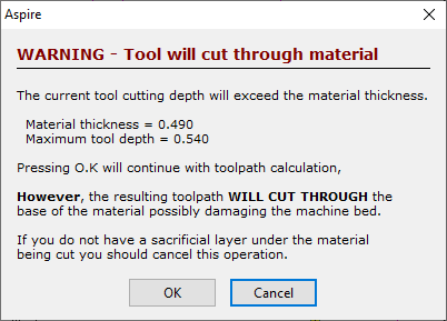
The cut depth has to be deeper that material thickness to ensure it cuts through. Usually add 0.05”
0.49” + 0.05” = 0.54”
Select same tool as before. The settings will be adjusted to match that of the calculator that was linked earlier. This will provide a faster cutting process without dulling the tool.
Set the outside machine vectors. This is so the tool follows the outside of the vector lines, ensuring proper dimensions. If the tool cut on the line, the entire profile would be undersized by the diameter of the tool
Turn on the add tabs feature and select add tabs
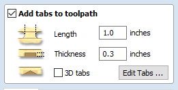
This opens the tab tool window
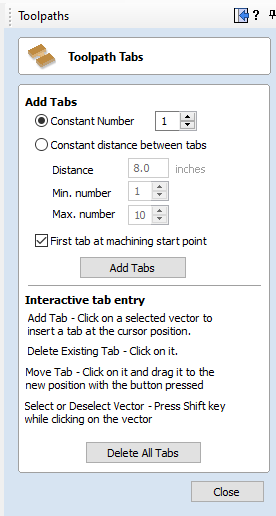
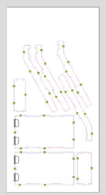
De-select First tab at machining starting point Tool can add tabs automatically or they can be placed manually. The automatic option didn’t work very well, as it placed the tabs on corners. This makes the tabs difficult to remove. To manually add tabs, move the cursor over the vectors and right clicking. Avoid internal slots. Difficult to remove and sand Tabs show as yellow boxes with the letter “T”
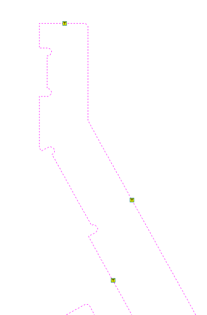
Not many are needed, just enough to hold the parts in place while cutting
Close the tab window
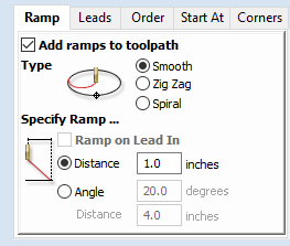
Turn on the Add ramps to toolpath options. Set type to smooth and distance to 1.0. Not using center cutting tool, so it can’t plunge straight down into material
Rename and click Calculate A warning box will appear to alert that the tool will cut completely through the material.
Chose preview all toolpaths again to see the the profile toolpaths as well
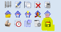
Toolpaths need to be post-processed into the proper code for machine being used. Select the save toolpath icon to open the window
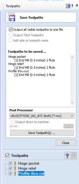
All of the toolpaths can be saved to one file because they are using the same tool. Select the Output all visible toolpaths to one file option. You’ll see which toolpaths will be included. Choose the correct post-processor from the drop-down. Make sure all of the toolpaths to be cut are checked. The paths will be cut in the order they are listed on the screen. The order can be changed if needed. Select Save toolpaths.
Document how you made something big(setting up machine, using fixtures, testing joints, adjusting feeds and speeds, depth of cut etc)
Machine setup
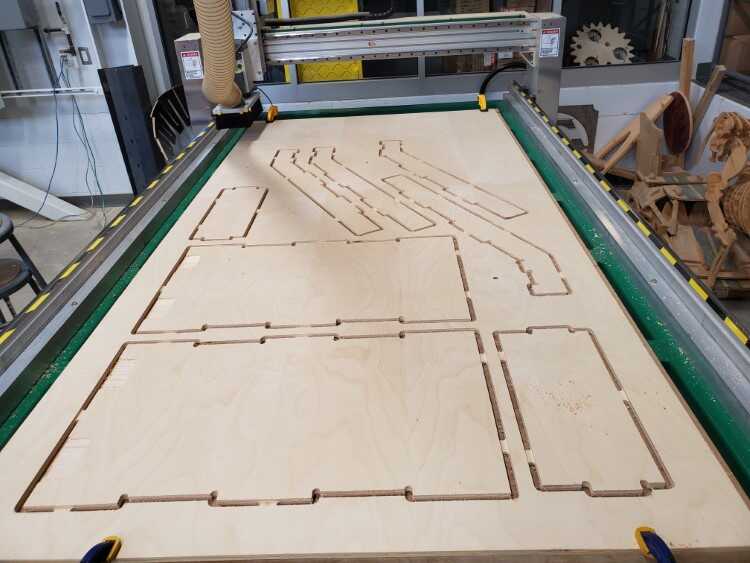
To cut the parts a Forest Scientific Velocity CNC router was used. It has a bed size of 4’x8’, so a full-sized sheet of plywood will fit.
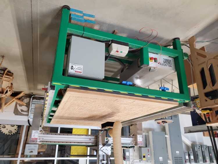
The Velocity has a sacrificial layer of MDF that allows for through-cutting of material
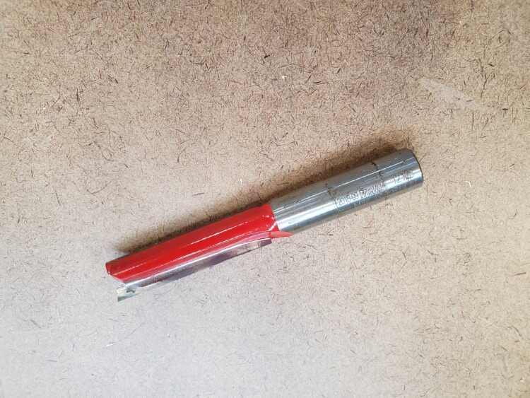
I programmed the CAM using an 0.5” end mill. This particular end mill is 2” long, has two flutes, and a 0.5” shank
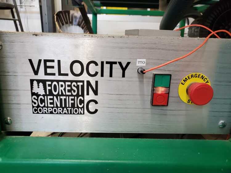
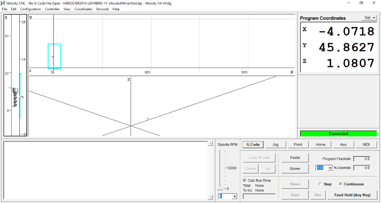
First, tool needs to be installed. Open the Velocity software to access the control interface

Power on the machine signal generator
Chose connect to connect computer to signal generator
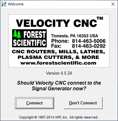
Read through safety guidelines and chose agree
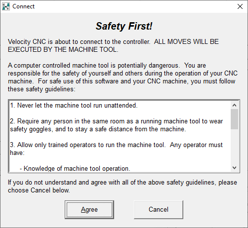
Now presented with Velocity software main interface screen
The spindle needs to be moved closer so the tool can be changed. To do this, select the velocity jog command to open jog window
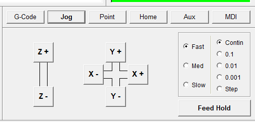
Set to contin for continuous movement
Using the arrow keys, jog the machine close to the front of the machine so the spindle can be accessed to the change tool
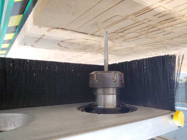
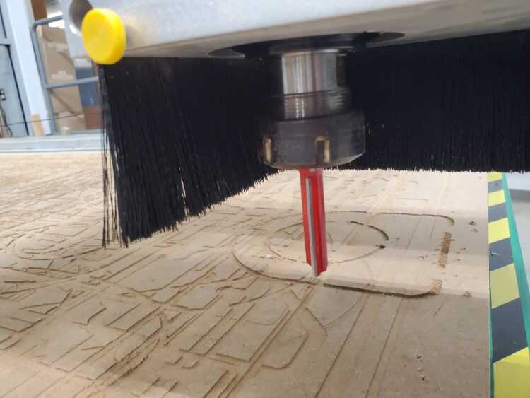
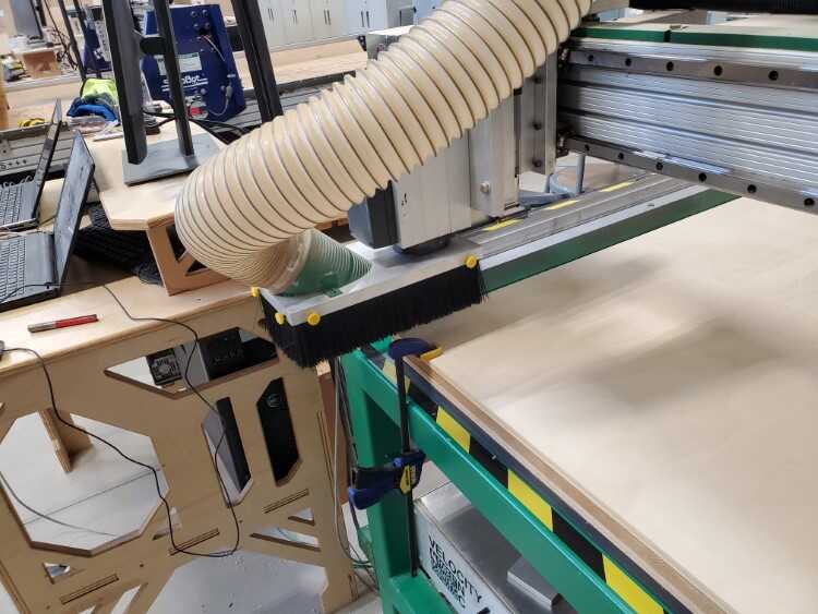
On the Velocity, loosen yellow thumb screws to remove dust collector brush
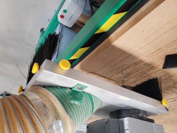
Exposed the spindle and gives access to collet nut
Use provided tools to loosen collet nut
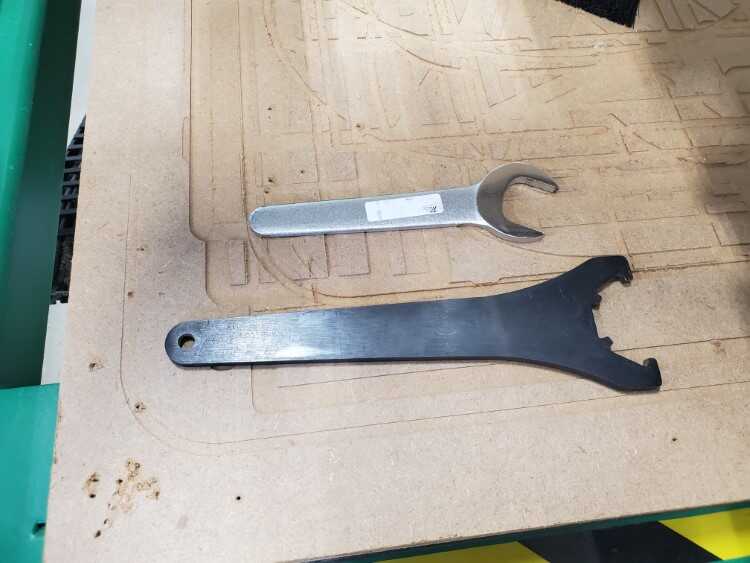
The silver wrench holds spindle in place while the black collet wrench loosens the collet nut
Be mindful which direction the nut is turning, be sure to loosen and not tighten
Remove the installed collet if it’s the wrong size and change to correct size. In this case a 0.25” was installed, so it will be replaced with a 0.5” collet
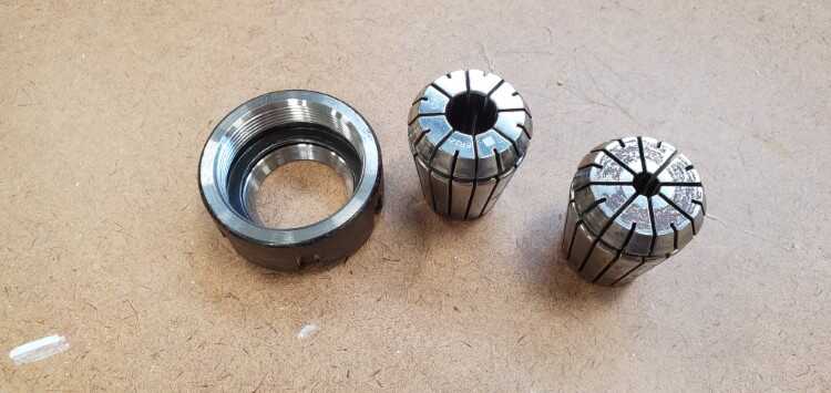
Snaps into the collet nut
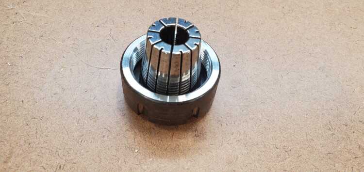
The Velocity used an ER32 collet size
Insert tool into collet. Some tools have a safe minimum install line. If not, as in this case, make sure at least 3/4 of shank
is inserted into collet
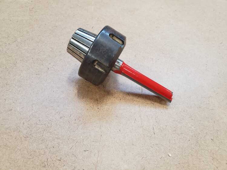
Gently thread collet nut onto spindle, be sure not to cross thread. Hand tighten while ensuring the tool didn’t slip out of the collet.
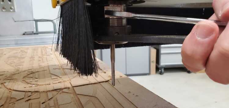
Finish by tightening collet nut with the wrenches
Re-install dust collector brush
Loading material
To load the material, use the jog window to move the spindle to the back of the machine.
Lay material onto sacrificial layer
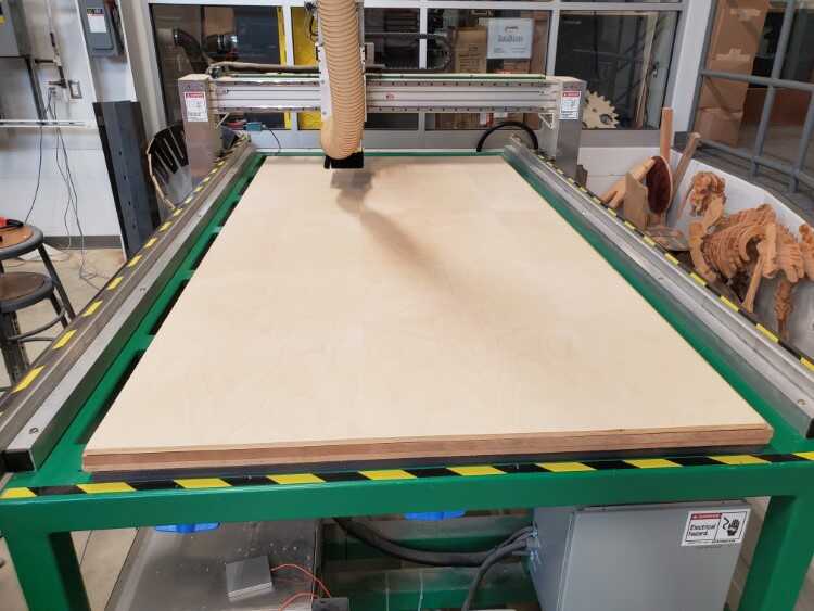
0.5” sheet of plywood
A 2” border gap was included in the CAM file allowing clamps can be used to secure the wood to the table
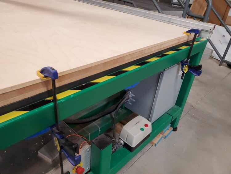
Velocity also has vacuum table, clamps are added security
To zero out the tool, or set the program home, sometimes called the material offset, use the Job window to bring the spindle close to the front left corners
We want to set the program home to match the datum point from our CAM setup
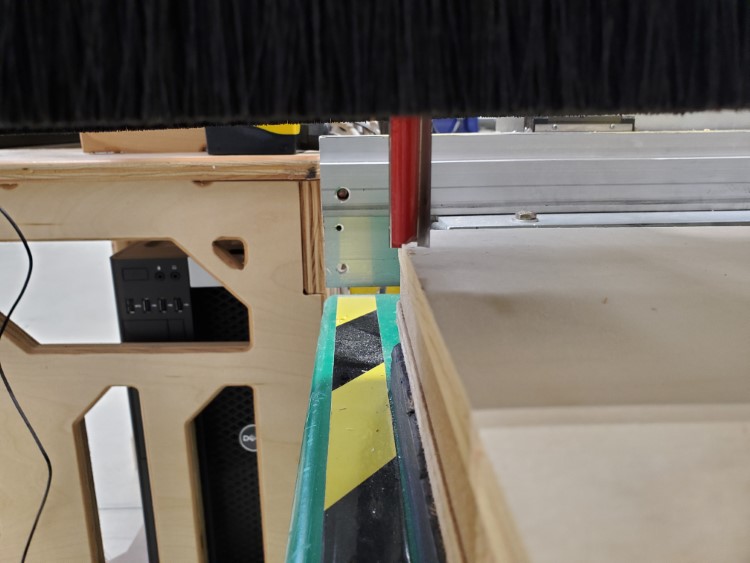
X axis will be zeroed first. Rotate tool so the blades are parallel to the X axis
Use the jog tool to move spindle until center of the tool is lined up with the edge of the material
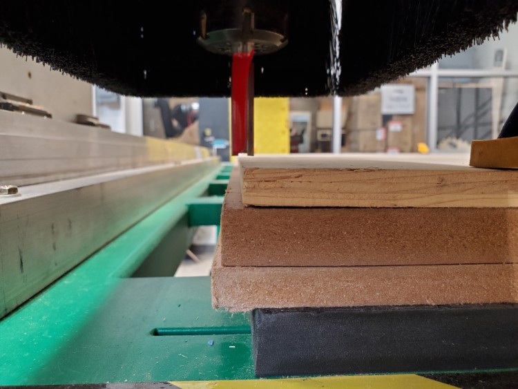
Note: jog tool will allows for incremental movement for fine-tuning
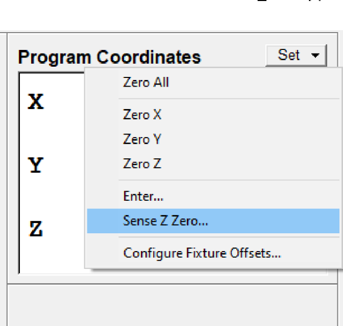
Select the Set drop down by program coordinates part of the screen
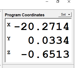
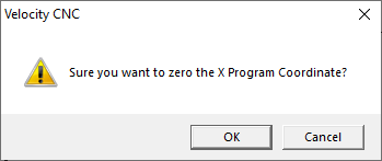
Choose the x axis
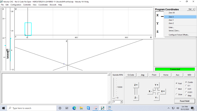
And click OK
Now the x zero point for the program is set
Repeat for y axis. Start by turning the tool 90 degrees
Set the y-zero same procedure as x axis
Now the zeros for both and x and y are set
Setting the z axis zero is automatic using touch plate Make sure the z axis touch plate is plugged in

Found on the front of the signal generator
Move x and y axes to central location of material and place the touch plate under the tool
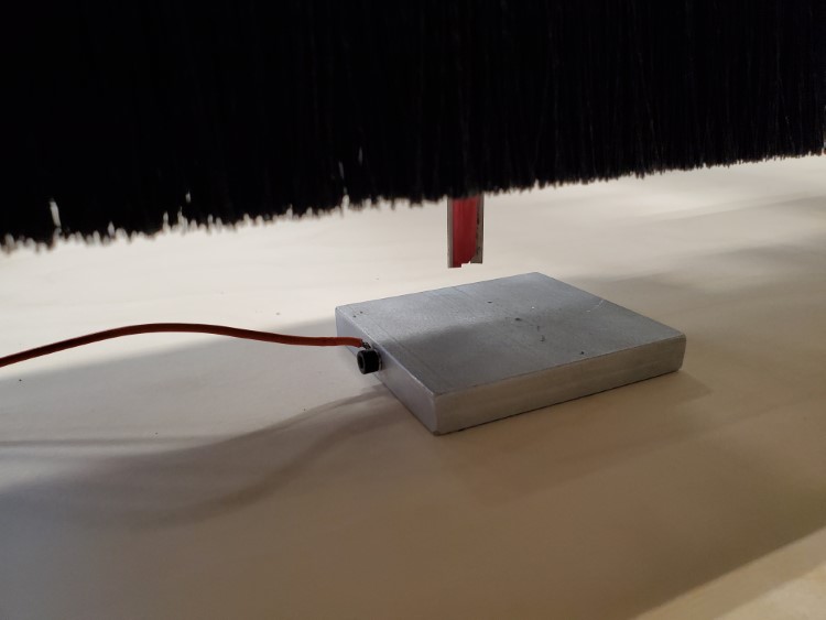
Go back to Set and chose Sense Z-zero…
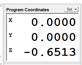
The z-axis will slowly move towards the bed and touch plate. When it touches, a circuit is completed, letting the machine know where the z-axis is. Now the z position is set. The machine knows the thickness of the touch plate and adds 0.10”. It parks the spindle at 0.60”
Loading the program
Select file and then Open G-Code
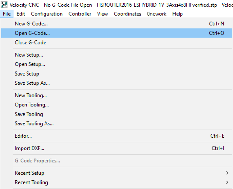
Select the correct file
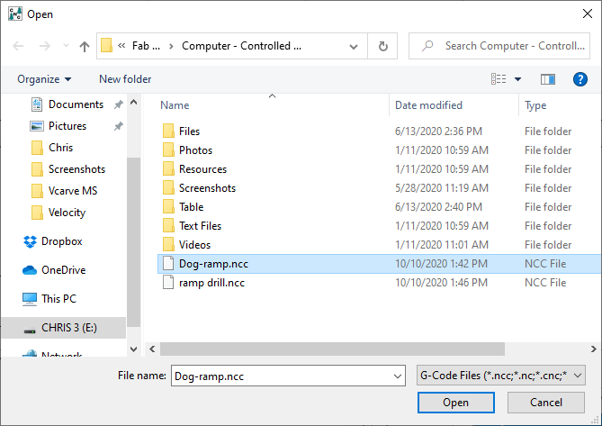
Programs shows both a visual simulation of g code as well as the code itself
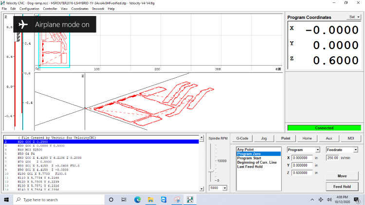
Select the G-Code window
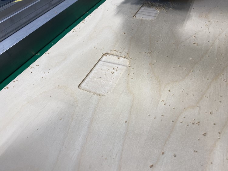
The cut hinge pocket
Blue lines indicate what has been cut
Keep vacuum table running and material clamped while cleaning saw dust, in case a part didn’t cut through
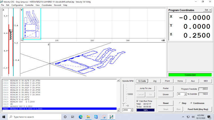
Everything looks good, can see the sacrificial board so it cut through
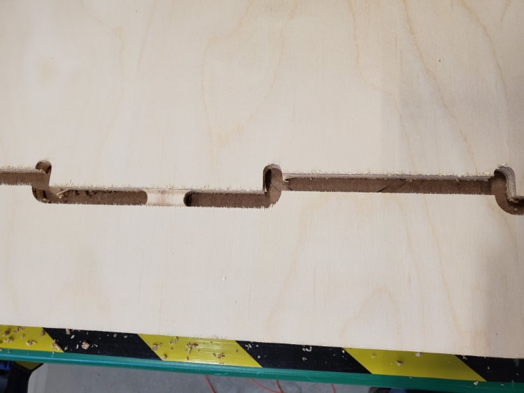
And the material is fully cut and the parts are ready to be removed
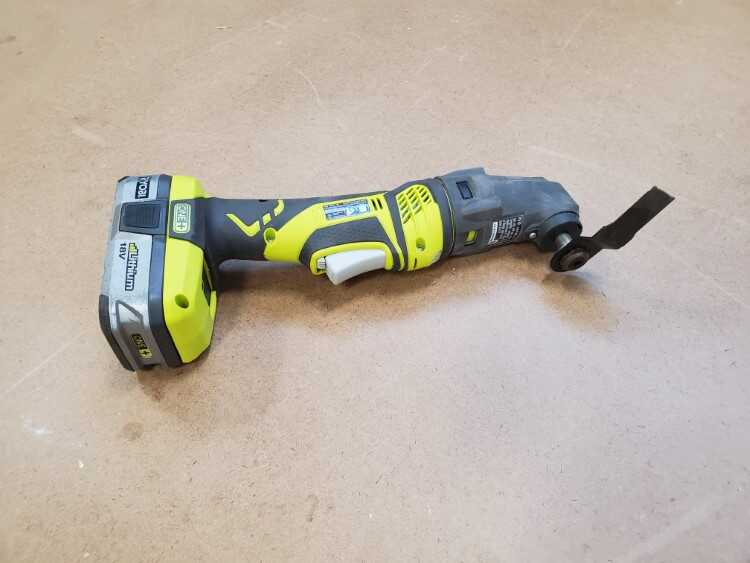
The parts are still connected to the board with the tabs setup in Aspire. Using an oscillating cutter to remove tabs makes life easier
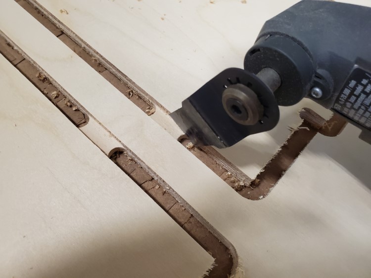
Parts are all cut out, but still rough, need sanding to remove rest of tabs and roughness
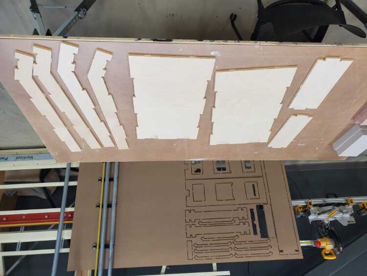
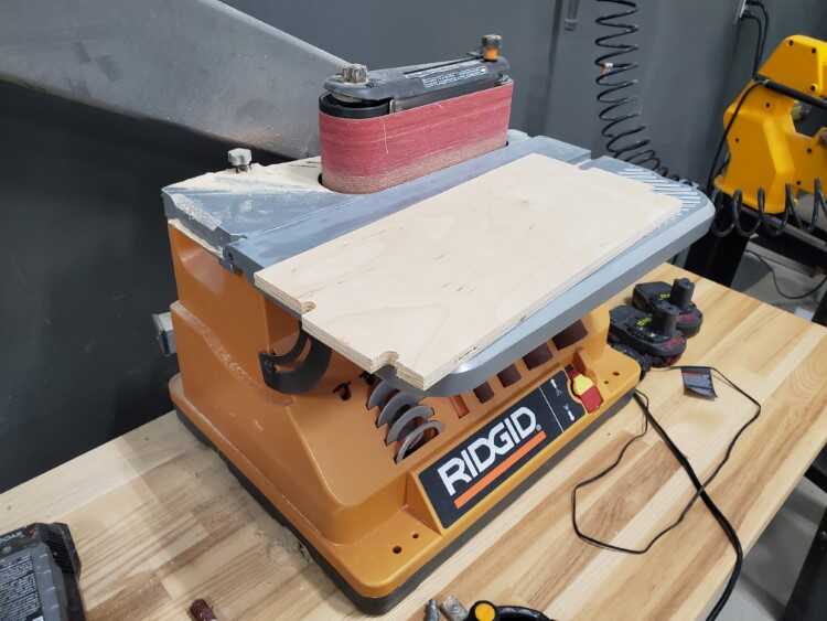
A combination of a hand sanding and a belt sander was used to clean up the edges
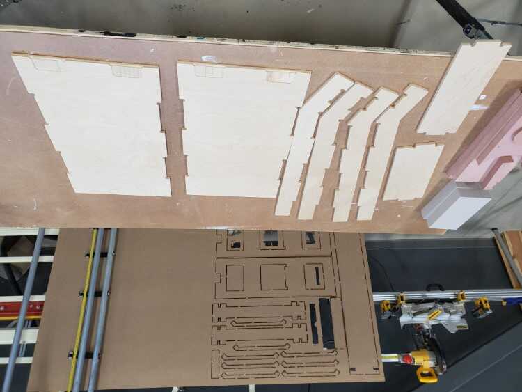
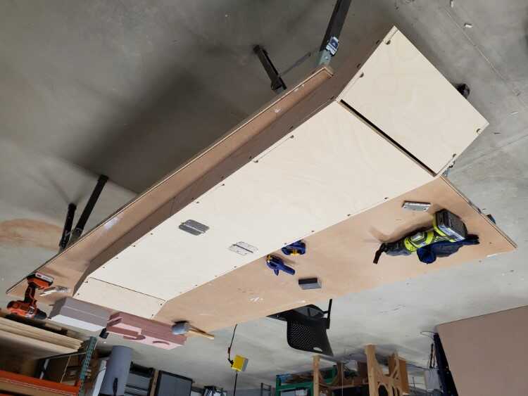
Cleaned and ready to assemble
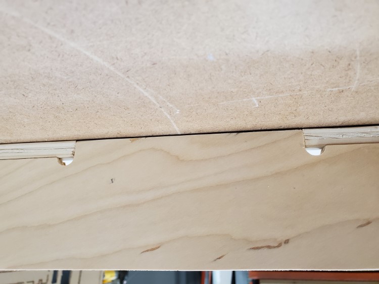
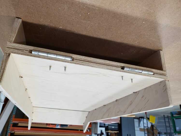
The tabs fit the slots well. They were tight enough to hold everything together, but didn’t need to be forced together with a hammer
The side panel was first
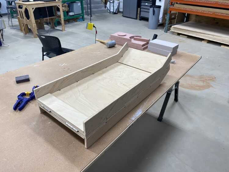
And the other pieces to compete the lower section
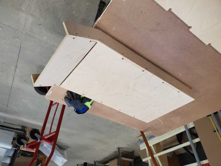
Repeat with the upper component
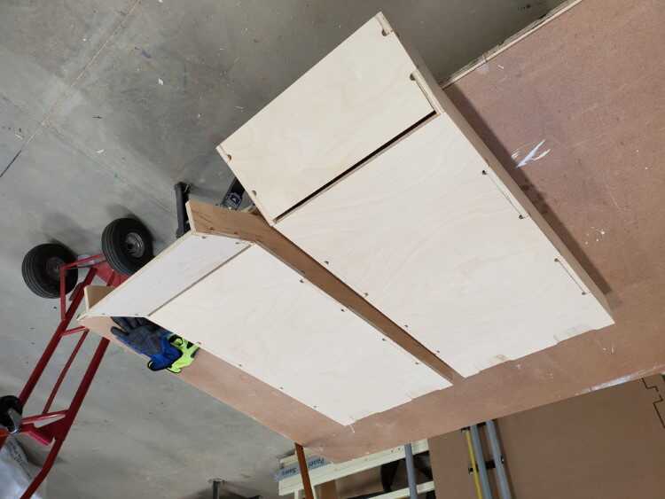
Next was to install the hinges
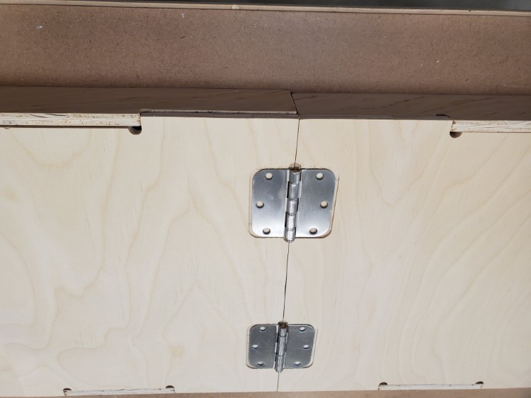
There were some issues with this. The screws were too long and came through the other side. As this is the walking surface, it needed to be addressed
Cutting them flush would weaken the hold of the screw, so I decided to use a small 2” wide piece of scrap to make a cleat. This gave an extra bonus of something the dogs to grip onto.
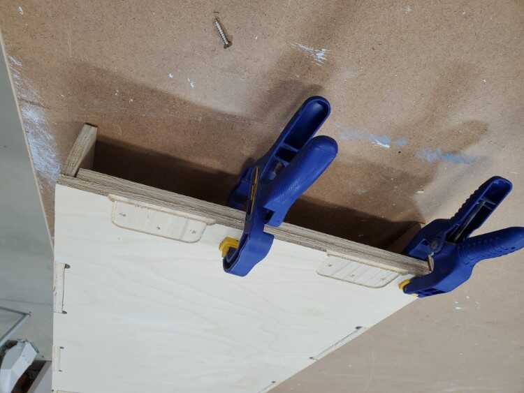
With cleat
The issues
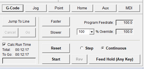
Machine started to vibrate or chatter. The feed rate seemed to be too high and possibly the tooling was starting to dull. I slowed it down during the cutting process to 80% fixed the issue. That put the Feed rate at 160min/min. A consequence of this was the parts ended up with a rough finish. A little sandpaper and elbow grease fixed that issue. Difficult to remove parts in middle of material. Had to use hand circular saw to cut down scrap as I went.
Files

This work is licensed under a Creative Commons Attribution-NonCommercial-ShareAlike 4.0 International License.