12. Output devices
For this assignment, I’m going to be using the second ATtiny84 modular board I created. The design and fabrication processes have been documented in previous weeks assignments
ATtiny84 Modular board
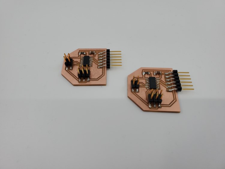
tiny84 modular boards
My final project is going to use addressable LED’s or Neopixels. For this weeks assignment, I’m going to be adding the addressable LED’s to my modular board and have them perform various animations.
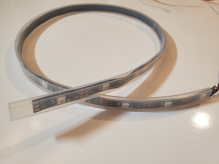
It was worth looking at the datasheet for them as well. The technical name is WS2812
The addressable LED’s have three connections. They require 5 volts, a ground connection that has to be shared with the microcontroller, and a data line connected to an output pin. I also looked at the current draw of each pixel. Each pixel is made up of three leds (red, green, blue). Each has a max current draw of 20mA. When colors start getting mixed, more than one of the leds can be lit per pixel, so power requirements can be surprisingly high.
A quick example: I’m using a strip of 20 pixels. If I were to light the entire strip red at maximum brightness, that’s 20mA * 20 pixels, or 0.4A. But, if I wanted the strip to be purple, then I’d have to mix the blue LED’s as well, adding another 0.4A for a total of 0.8A. Simply changing a color doubled the current needed. Power requirements should always be considered when using these.
Programming
First, I need to setup the hardware. The modular board has a header that provides 5 volts, ground, and has two I/O pins. The addressable LED’s only require one pin, so in this case I’ll use pin 7 in the IDE. That would be pin 6 on the chip and PA7 on the schematic.
The TinyISP and Arduino IDE are already setup to program an ATtiny84 from the previous assignments. I’m going to use the Adafruit Neopixel library for my first test. Specifically, the tinyNeoPixel library. It’s a library designed for the ATtiny family of microcontrollers.
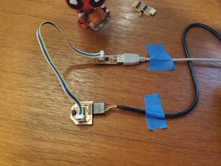
Modular board hooked up to TinyISP
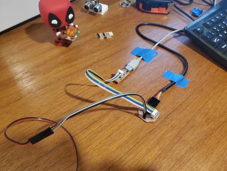
Black for ground, white for 5 volts, gray for the data line
Test 1
The first thing is to open an example sketch from the tinyNeoPixel library
![]()
File=>Examples=>tinyNeoPixel=>simple
The ‘simple’ example was selected as it will be easier to troubleshoot should something go wrong. A few variable need to be adjusted before the program can be loaded. The data pin needs to be changed to pin 7. The number of pixels should be changed to match the number on the strip, but I’m going to set it for three LED’s to be safe and protect from a power draw issue.
// NeoPixel Ring simple sketch (c) 2013 Shae Erisson
// released under the GPLv3 license to match the rest of the AdaFruit NeoPixel library

#if (F_CPU>7370000) //neopixel library required 7.37MHz minimum clock speed; this line is used to skip this sketch in internal testing. It is not needed in your sketches.

#include <tinyNeoPixel.h>


// Which pin on the Arduino is connected to the NeoPixels?
#define PIN            7

// How many NeoPixels are attached to the Arduino?
#define NUMPIXELS      3

// When we setup the NeoPixel library, we tell it how many pixels, and which pin to use to send signals.
// Note that for older NeoPixel strips you might need to change the third parameter--see the strandtest
// example for more information on possible values.
tinyNeoPixel pixels = tinyNeoPixel(NUMPIXELS, PIN, NEO_GRB + NEO_KHZ800);

int delayval = 500; // delay for half a second

void setup() {

  pixels.begin(); // This initializes the NeoPixel library.
}

void loop() {

  // For a set of NeoPixels the first NeoPixel is 0, second is 1, all the way up to the count of pixels minus one.

  for(int i=0;i<NUMPIXELS;i++){

    // pixels.Color takes RGB values, from 0,0,0 up to 255,255,255
    pixels.setPixelColor(i, pixels.Color(0,150,0)); // Moderately bright green color.

    pixels.show(); // This sends the updated pixel color to the hardware.

    delay(delayval); // Delay for a period of time (in milliseconds).

  }
}
#else //neopixel library required 7.37MHz minimum clock speed; these and following lines are used to skip this sketch in internal testing. It is not needed in your sketches.
#warning "Neopixel control requires F_CPU > 7.37MHz"
void setup() {}
void loop() {}
#endif// NeoPixel Ring simple sketch (c) 2013 Shae Erisson
// released under the GPLv3 license to match the rest of the AdaFruit NeoPixel library

#if (F_CPU>7370000) //neopixel library required 7.37MHz minimum clock speed; this line is used to skip this sketch in internal testing. It is not needed in your sketches.

#include <tinyNeoPixel.h>


// Which pin on the Arduino is connected to the NeoPixels?
#define PIN            7

// How many NeoPixels are attached to the Arduino?
#define NUMPIXELS      3

// When we setup the NeoPixel library, we tell it how many pixels, and which pin to use to send signals.
// Note that for older NeoPixel strips you might need to change the third parameter--see the strandtest
// example for more information on possible values.
tinyNeoPixel pixels = tinyNeoPixel(NUMPIXELS, PIN, NEO_GRB + NEO_KHZ800);

int delayval = 500; // delay for half a second

void setup() {

  pixels.begin(); // This initializes the NeoPixel library.
}

void loop() {

  // For a set of NeoPixels the first NeoPixel is 0, second is 1, all the way up to the count of pixels minus one.

  for(int i=0;i<NUMPIXELS;i++){

    // pixels.Color takes RGB values, from 0,0,0 up to 255,255,255
    pixels.setPixelColor(i, pixels.Color(0,150,0)); // Moderately bright green color.

    pixels.show(); // This sends the updated pixel color to the hardware.

    delay(delayval); // Delay for a period of time (in milliseconds).

  }
}
#else //neopixel library required 7.37MHz minimum clock speed; these and following lines are used to skip this sketch in internal testing. It is not needed in your sketches.
#warning "Neopixel control requires F_CPU > 7.37MHz"
void setup() {}
void loop() {}
#endif
My first attempt to upload the file was met with an error message. The tinyNeoPixel library requires a minimum clock speed of 8MHz.
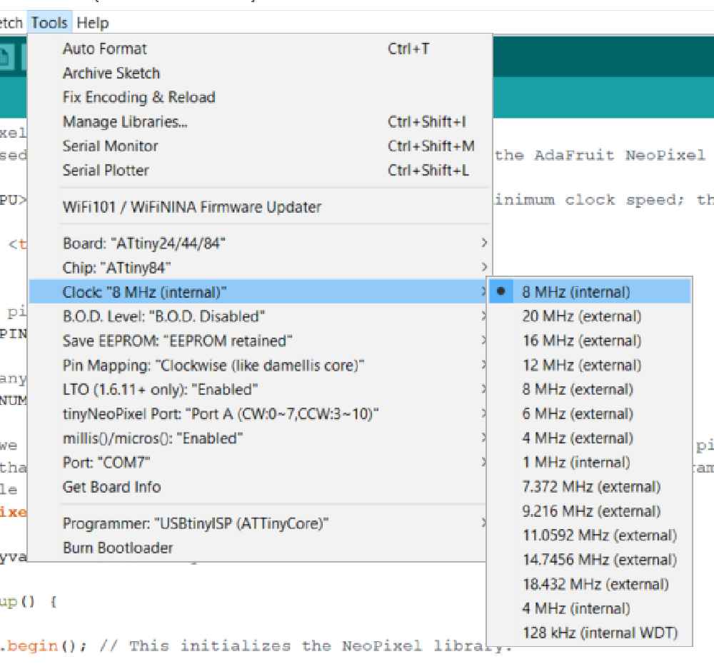
Tools=>Clock=>8MHz(internal)
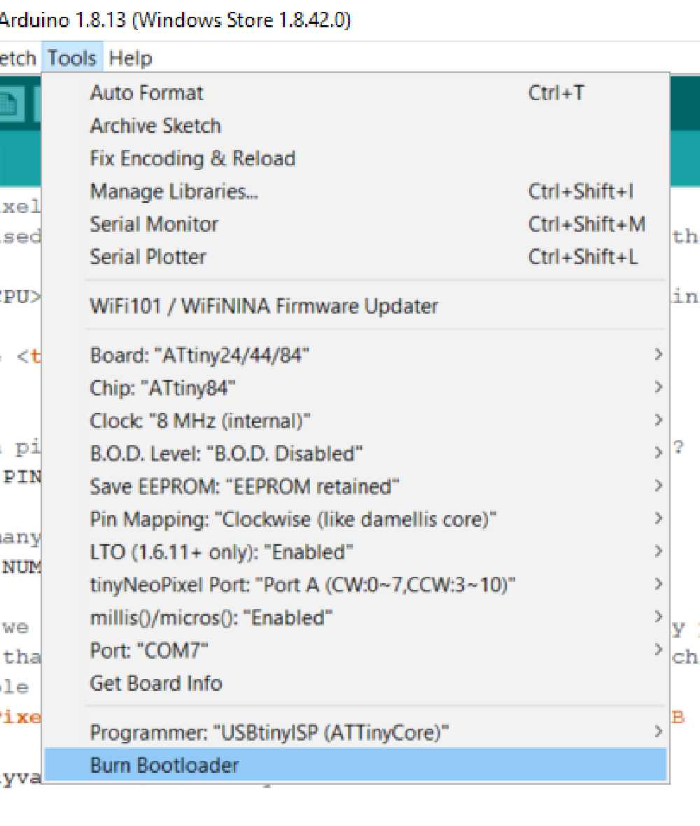
I uploaded the sketch again and only one LED lit and it was the wrong color (I was looking for green). I know that addressable LED’s are very dependent on timing, so I assumed the timing was off. I looked back at the datasheet for the ATtiny84 and found the internal clock is set for 1MHz. Simply changing the clock setting in the drop down menu doesn’t actually change the clock speed. The clock fuses need to be set as well. To do that, I had to burn the bootloader to set the fuses for 8MHz.
After that I uploaded the sketch again, expecting three green LED’s to be lit
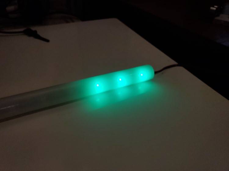
Light is green....
Test 2
The next test was to animate the LEDs. I went back to the examples and opened the strandtest sketch. Again, I had to change the pin to 7, but this time I increased the LED count to 10
#if (F_CPU>7370000) //neopixel library required 7.37MHz minimum clock speed; this line is used to skip this sketch in internal testing. It is not needed in your sketches.

#include <tinyNeoPixel_Static.h>

#define PIN 7

// Parameter 1 = number of pixels in strip
// Parameter 2 = Arduino pin number (most are valid)
// Parameter 3 = pixel type flags, add together as needed:
//   NEO_GRB     Pixels are wired for GRB bitstream (most NeoPixel products)
//   NEO_RGB     Pixels are wired for RGB bitstream (v1 FLORA pixels, not v2)
// Parameter 4 = array to store pixel data in

#define NUMPIXELS 10

// Since this is for the static version of the library, we need to supply the pixel array
// This saves space by eliminating use of malloc() and free(), and makes the RAM used for
// the frame buffer show up when the sketch is compiled.

byte pixels[NUMPIXELS * 3];

// When we setup the NeoPixel library, we tell it how many pixels, and which pin to use to send signals.
// Note that for older NeoPixel strips you might need to change the third parameter--see the strandtest
// example for more information on possible values. Finally, for the 4th argument we pass the array we
// defined above.

tinyNeoPixel strip = tinyNeoPixel(NUMPIXELS, PIN, NEO_GRB, pixels);

// IMPORTANT: To reduce NeoPixel burnout risk, add 1000 uF capacitor across
// pixel power leads, add 300 - 500 Ohm resistor on first pixel's data input
// and minimize distance between Arduino and first pixel.  Avoid connecting
// on a live circuit...if you must, connect GND first.

void setup() {
  pinMode(PIN,OUTPUT); //set pin output - this is not done internally by the library for Static version of library
  //strip.begin(); //Static version does not use this.
  strip.show(); // Initialize all pixels to 'off'
}

void loop() {
  // Some example procedures showing how to display to the pixels:
  colorWipe(strip.Color(255, 0, 0), 50); // Red
  colorWipe(strip.Color(0, 255, 0), 50); // Green
  colorWipe(strip.Color(0, 0, 255), 50); // Blue
  // Send a theater pixel chase in...
  theaterChase(strip.Color(127, 127, 127), 50); // White
  theaterChase(strip.Color(127, 0, 0), 50); // Red
  theaterChase(strip.Color(0, 0, 127), 50); // Blue

  rainbow(20);
  rainbowCycle(20);
  theaterChaseRainbow(50);
}

// Fill the dots one after the other with a color
void colorWipe(uint32_t c, uint8_t wait) {
  for(uint16_t i=0; i<strip.numPixels(); i++) {
    strip.setPixelColor(i, c);
    strip.show();
    delay(wait);
  }
}

void rainbow(uint8_t wait) {
  uint16_t i, j;

  for(j=0; j<256; j++) {
    for(i=0; i<strip.numPixels(); i++) {
      strip.setPixelColor(i, Wheel((i+j) & 255));
    }
    strip.show();
    delay(wait);
  }
}

// Slightly different, this makes the rainbow equally distributed throughout
void rainbowCycle(uint8_t wait) {
  uint16_t i, j;

  for(j=0; j<256*5; j++) { // 5 cycles of all colors on wheel
    for(i=0; i< strip.numPixels(); i++) {
      strip.setPixelColor(i, Wheel(((i * 256 / strip.numPixels()) + j) & 255));
    }
    strip.show();
    delay(wait);
  }
}

//Theatre-style crawling lights.
void theaterChase(uint32_t c, uint8_t wait) {
  for (int j=0; j<10; j++) {  //do 10 cycles of chasing
    for (int q=0; q < 3; q++) {
      for (int i=0; i < strip.numPixels(); i=i+3) {
        strip.setPixelColor(i+q, c);    //turn every third pixel on
      }
      strip.show();

      delay(wait);

      for (int i=0; i < strip.numPixels(); i=i+3) {
        strip.setPixelColor(i+q, 0);        //turn every third pixel off
      }
    }
  }
}

//Theatre-style crawling lights with rainbow effect
void theaterChaseRainbow(uint8_t wait) {
  for (int j=0; j < 256; j++) {     // cycle all 256 colors in the wheel
    for (int q=0; q < 3; q++) {
      for (int i=0; i < strip.numPixels(); i=i+3) {
        strip.setPixelColor(i+q, Wheel( (i+j) % 255));    //turn every third pixel on
      }
      strip.show();

      delay(wait);

      for (int i=0; i < strip.numPixels(); i=i+3) {
        strip.setPixelColor(i+q, 0);        //turn every third pixel off
      }
    }
  }
}

// Input a value 0 to 255 to get a color value.
// The colours are a transition r - g - b - back to r.
uint32_t Wheel(byte WheelPos) {
  WheelPos = 255 - WheelPos;
  if(WheelPos < 85) {
    return strip.Color(255 - WheelPos * 3, 0, WheelPos * 3);
  }
  if(WheelPos < 170) {
    WheelPos -= 85;
    return strip.Color(0, WheelPos * 3, 255 - WheelPos * 3);
  }
  WheelPos -= 170;
  return strip.Color(WheelPos * 3, 255 - WheelPos * 3, 0);
}
#else //neopixel library required 7.37MHz minimum clock speed; these and following lines are used to skip this sketch in internal testing. It is not needed in your sketches.
#warning "Neopixel control requires F_CPU > 7.37MHz"
void setup() {}
void loop() {}
#endif
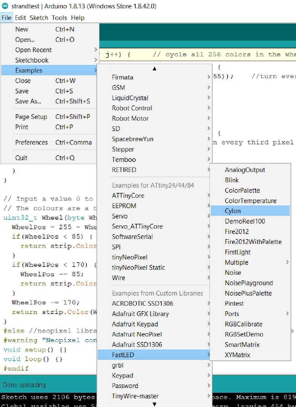
Test 3
Now that I know the neoPixel library works, I wanted to test the FastLED library, which is what is going to be used in my final project. I went to examples again, this time selecting FastLED and the cylon sketch
#include <FastLED.h>

// How many leds in your strip?
#define NUM_LEDS 20

// For led chips like Neopixels, which have a data line, ground, and power, you just
// need to define DATA_PIN.  For led chipsets that are SPI based (four wires - data, clock,
// ground, and power), like the LPD8806, define both DATA_PIN and CLOCK_PIN
#define DATA_PIN 7
//#define CLOCK_PIN 13

// Define the array of leds
CRGB leds[NUM_LEDS];

void setup() {
    Serial.begin(57600);
    Serial.println("resetting");
    LEDS.addLeds<WS2812,DATA_PIN,RGB>(leds,NUM_LEDS);
    LEDS.setBrightness(84);
}

void fadeall() { for(int i = 0; i < NUM_LEDS; i++) { leds[i].nscale8(250); } }

void loop() {
    static uint8_t hue = 0;
    Serial.print("x");
    // First slide the led in one direction
    for(int i = 0; i < NUM_LEDS; i++) {
        // Set the i'th led to red
        leds[i] = CHSV(hue++, 255, 255);
        // Show the leds
        FastLED.show();
        // now that we've shown the leds, reset the i'th led to black
        // leds[i] = CRGB::Black;
        fadeall();
        // Wait a little bit before we loop around and do it again
        delay(10);
    }
    Serial.print("x");

    // Now go in the other direction.
    for(int i = (NUM_LEDS)-1; i >= 0; i--) {
        // Set the i'th led to red
        leds[i] = CHSV(hue++, 255, 255);
        // Show the leds
        FastLED.show();
        // now that we've shown the leds, reset the i'th led to black
        // leds[i] = CRGB::Black;
        fadeall();
        // Wait a little bit before we loop around and do it again
        delay(10);
    }
}
Again, I changed the data pin to 7, increased the number of LED’s to the full 20 and uploaded the sketch
Test 4
Now that I know the FastLED library works with the ATtiny84, I wanted to try one of my own custom animations. This animation is inspired by Knight Rider and Battlestar Galactica. It’s known as a Larson scanner, named after the person who invented it. This is similar to the previous animation, but doesn’t use the specialized calls of the FastLED library. There are also some variables that can be changed as well. The color is static and selectable and the size, speed, and bounce back of the scanner can be adjusted. It utilizes the HSV (Hue, Saturation, Brightness) color picking that FastLED offers. I talk more about this on the project development page.
/*
 * Knight Rider or Larson scanner style animation
 * Selectable colors based in CHSV values
 *
 * by Christopher Leon
 */
#include <FastLED.h>

#define PIXEL_PIN 7
#define PIXELS 20
#define MAX_BRIGHTNESS 192

#define SCAN_WIDTH 3 //number of pixels sets width of "scanner"
#define SCAN_SPEED 30 //how fast it moves larger number is slower speed
#define SCAN_RETURN 40 //how long it pauses before changing direction


CRGB leds[PIXELS];

/*
HSV Color Arrays
HUE Values (0-255)
0 = RED
32 = ORANGE
64 = YELLOW
96 = GREEN
128 = AQUA
160 = BLUE
192 = PURPLE
224 = PINK
*/

//HSV Arrays (HUE, SATURATION, BRIGHTNESS)
int BLACK[3] = {0,0,0};
int WHITE[3] = {0,0,255}; //draws a lot of current
int DIMWHTIE[3] = {0,0,192}; //less current draw
int RED[3] = {0,255,255};
int LTRED[3] = {0,170,255};
int ORANGE[3] = {32,255,255};
int LTORANGE[3] = {32,170,255};
int YELLOW[3] = {64, 255,255};
int LTYELLOW[3] = {64,170,255};
int GREEN[3] = {96,255,255};
int LTGREN[3] = {96,170,255};
int AQUA[3] = {128,255,255};
int BLUE[3] = {160,255,255};
int LTBLUE[3] = {160,170,255};
int PURPLE[3] = {192,255,255};
int LTPURPLE[3] = {192,170,255};
int PINK[3] = {224,255,255};


void setup()
{
  FastLED.addLeds<WS2811, PIXEL_PIN, GRB>(leds, PIXELS);
  LEDS.setBrightness(MAX_BRIGHTNESS);
}

void loop()
{
CylonBounce(RED); //Enter any color from list above
}


void CylonBounce(int color[3])
{
  for(int i = 0; i < PIXELS-SCAN_WIDTH-2; i++)
  {
    for(int i=0; i <PIXELS; i++)
    {
     leds[i] = CRGB(0,0,0);
    }
    leds[i] = CHSV(color[0],color[1],(color[2]/5));

    for(int j = 1; j <= SCAN_WIDTH; j++)
    {
      leds[i+j] = CHSV(color[0],color[1],color[2]);
    }
    leds[i+SCAN_WIDTH+1] = CHSV(color[0],color[1],(color[2]/5));

    FastLED.show();
    delay(SCAN_SPEED);
  }

 delay(SCAN_RETURN);


  for(int i = PIXELS-SCAN_WIDTH-2; i > 0; i--)
  {
    for(int i=0; i<PIXELS; i++)
    {
      leds[i] = CRGB(0,0,0);
    }

    leds[i] = CHSV(color[0],color[1],(color[2]/5));

    for(int j = 1; j <= SCAN_WIDTH; j++)
    {
      leds[i+j] = CHSV(color[0],color[1],color[2]);
    }
    leds[i+SCAN_WIDTH+1] = CHSV(color[0],color[1],(color[2]/5));

    FastLED.show();
    delay(SCAN_SPEED);
  }
  delay(SCAN_RETURN);
}
You can almost hear the theme song…
Conclusions
I learned a lot from this assignment. Using microcontrollers like the ATtiny84 is both similar and very different from Arduino’s. The Arduino has a lot of on-board functionality that can be taken for granted. Memory, storage, timing, are all things I had to consider when developing this board. Not knowing that the bootloader had to be used to set the fuses set me back by a few hours. If I were to redesign this board, I would include a crystal for external timing, and add one or two more I/O pins for more options. I would also include on-board LED’s for debugging purposes.
Files

This work is licensed under a Creative Commons Attribution-NonCommercial-ShareAlike 4.0 International License.