14. Networking and communications
ATtiny84 to Arduino
Hardware
I started with the ATtiny84 modular board I designed for Input and output week. This board will also be used for my final project
To utilize the I2C protocol, I needed access to the SDA and SCL pins on both the modular board and the Arduino Uno. On the Uno, pins A4 and A5 are SDA and SCL, respectively. On my modular board, I can reuse pins from the six pin header used for programming the chip. That header already connects to pin 7 (PA6) and pin 9 (PA4), again, SDA and SCL, respectively. To connect the hardware, I connected the SDA pin from the modular board to pin A4 and the SCL pin to pin A5 on the Arduino. I did learn that a pull-up resistor is needed for this type of connection. I ended up using a 10K ohm for both lines.
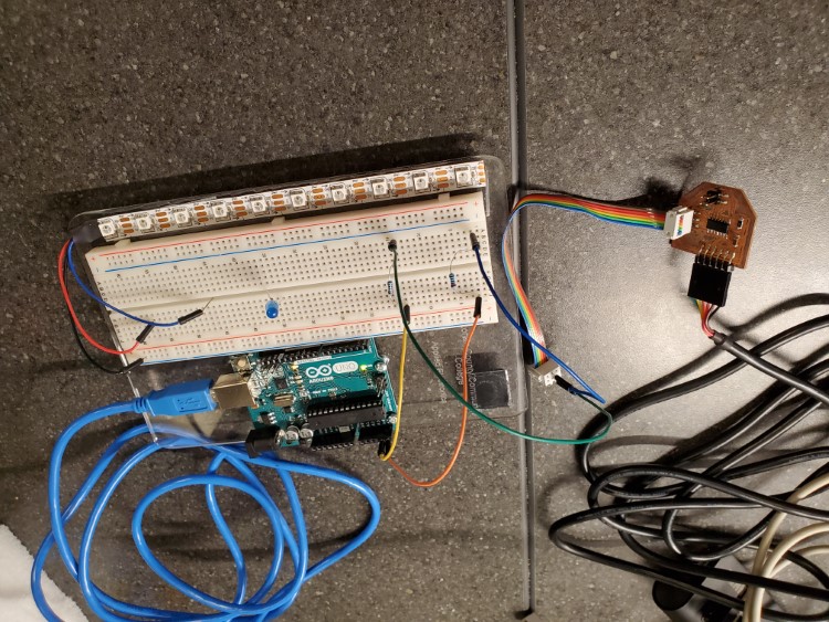
Breadboards, I know…
Programming
After doing some research, I decided to use the Wire.h library for this project. The native Wire.h library doesn’t support the ATtiny84, but the ATtinyCore board library has a variant that will compile for the ATtiny84.
I followed some basic tutorials and got a basic program to run. The modular board as a slave sending data to the Arduino acting as a master. The Arduino would then display that data via the serial monitor. From what I learned from the tutorials, I decided to try to write a more interactive code. An LED was added to the Arduino Uno, connected to pin 10. That pin was set as an output. The code requests data from a specific slave address on the I2C bus, in this case address 8. It also looks for a specific number of bytes, set to 1 in this code. The code then reads the requested data, stores it as an int variable and prints it to the serial monitor. That value is also used in an if/else statement. If the requested value is 1( or, HIGH), the LED turns on, otherwise, the LED turns off. Then the code pauses for once second and repeats.
 //Master code for Ardino Uno/ATtiny84 I2C connection.
//for Arduino Uno
//by
//Christopher Leon

#include <Wire.h> //Wire library for Arudino Uno
int LEDPin = 10; //defines the pin the LED is connected too

void setup()
{
  Wire.begin(); // join i2c bus
  Serial.begin(9600);
  pinMode(LEDPin, OUTPUT); //set the LED pin to an output
}

void loop()
{
  Wire.requestFrom(8, 1); // first value is the address of the slave, second value is the number of bytes to expect

  while (Wire.available())
  {
    int x = Wire.read(); // receive a byte as an integer
    Serial.println(x); // print the value
    if (x == 1)
      digitalWrite(LEDPin, HIGH); //If the incoming value is HIGH, or 1, turn the LED on, otherwise, turn it off
    else {
      digitalWrite(LEDPin, LOW);
    }
  }
  delay(1000);
}
The slave code for the ATtiny84 modular board sets up an input pin for the button on pin 7. The bus address is set to 8 using the Wire.begin command. Using Wire.onRequest, the slave waits for a request from the master. Once it receives a request, it runs the defined function, here being buttonEvent. Once a request is received, the function reads the state of the button and stores it as an int variable. LOW will read as 0 and HIGH will read as 1. That value is then sent to the master using the Wire.write command.
int BTNPin = 7; //defines the pin which the button is connected too

void setup()
{
  Wire.begin(8);                // join i2c bus with address #8
  Wire.onRequest(buttonEvent); // start looking for requests from a master device
  pinMode(BTNPin, INPUT); //sets the button pin to an input
}

void loop()
{
  delay(100);
}

// function that executes whenever data is requested by master
void buttonEvent()
{
  int x = digitalRead(BTNPin); //read the state of the button and store the value as x
  Wire.write(x); //send x value to the master
}
What I learned
I used the I2C protocol to communicate between the two boards. It only needs two wires to communicate, which makes the hardware connections simple. I did learn that a pull up resistor is needed on the lines, however. I used a 4.7K ohm resistor for this assignment. The I2C devices are given individual network addresses, so multiple devices can be used with a single master. Network protocols can be very powerful tools. In the case with my final project, the addressable LED’s require most of the computing power of the ATtiny84, so a second ATtiny84 is being used to process the incoming data from the ultrasonic sensor. Using the network protocol, I can then relay the information needed to activate different animation subroutines.
Programming process
I used the same programming processes I learned working on other assignments:
Issues
The only issue I really had was the data being corrupt when I sent it from the ATtiny84 to the Arduino. The serial monitor would read backwards question marks, or only the value 255. To fix this, I first changed the library being used with the ATtiny84, I then added resistors to the SDA and SDL connections. After that, everything fell into place.
Files

This work is licensed under a Creative Commons Attribution-NonCommercial-ShareAlike 4.0 International License.