10. Molding and casting
Group projects
Some insights and important information from the MDS sheets and directions of both the ReoFlex 30 and the Smoothcast 325 can be found on the group page
Design
Documented how you designed 3d mould and created rough and finish passes (with settings)
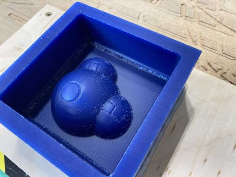
Vectric Aspire was used to create both the 3D model and generate the toolpaths. The goal was to create a small, castable water molecule. The material used to produce the mold is blue machinable wax.
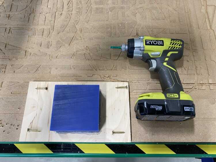
The first step was to measure the wax block, it measured 4” x 4” x 2”. Next, it was adhered to a small sheet of plywood with double-stick carpet tape and hot glue.
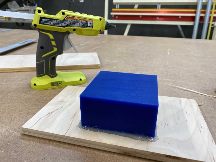
The purpose of adhering the wax to the wood is to allow for securing it onto the CNC router
With the block measured, a new file was created in Aspire and the material size was set. This was documented during a previous assignment:
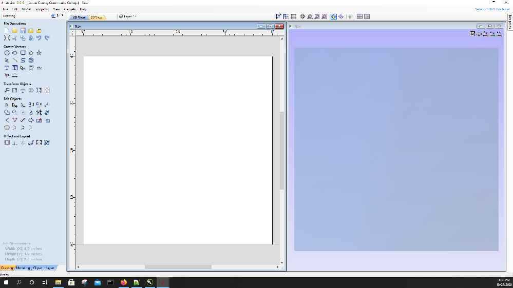
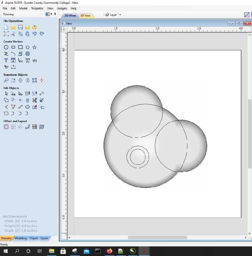
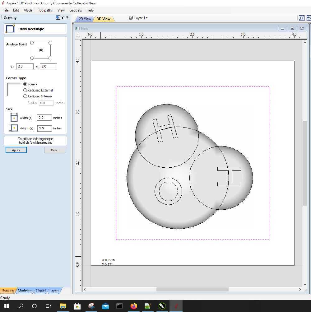
Set the display to show both the CAD and 3D windows by clicking on arrange views vertically button

The window should look like this. This will allow me to see a 3D render of the object as I design it
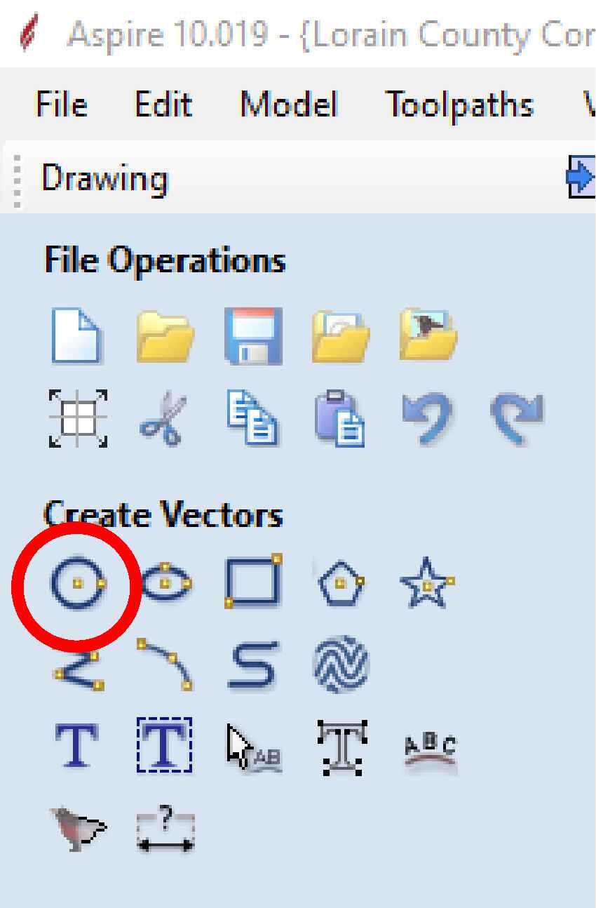
The model starts with a 2D drawing. In 2D, a water molecule is just one large circle with two smaller circles on either side. Select the draw circle tool from the create vectors panel on the left side of the screen
Move back to the CAD window and left-click and drag to draw the first circle
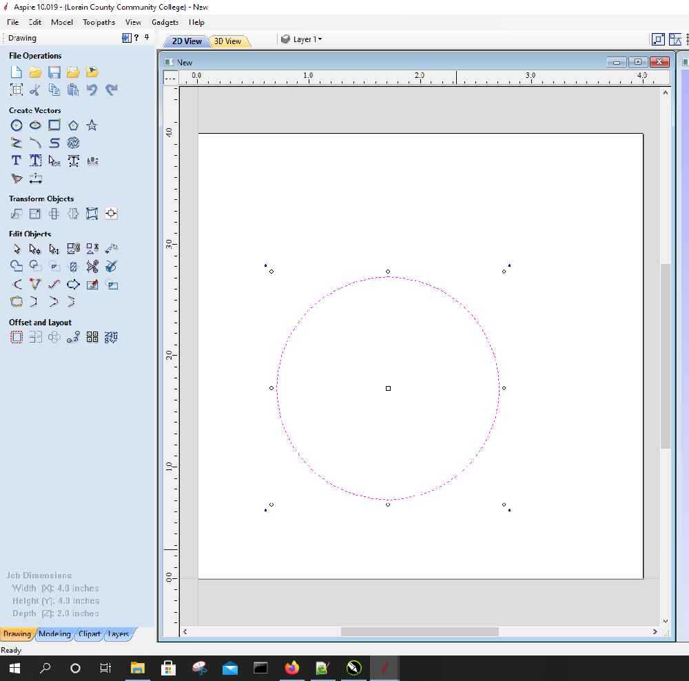
Now repeat with a smaller circle
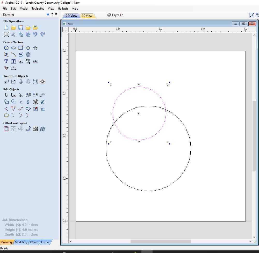
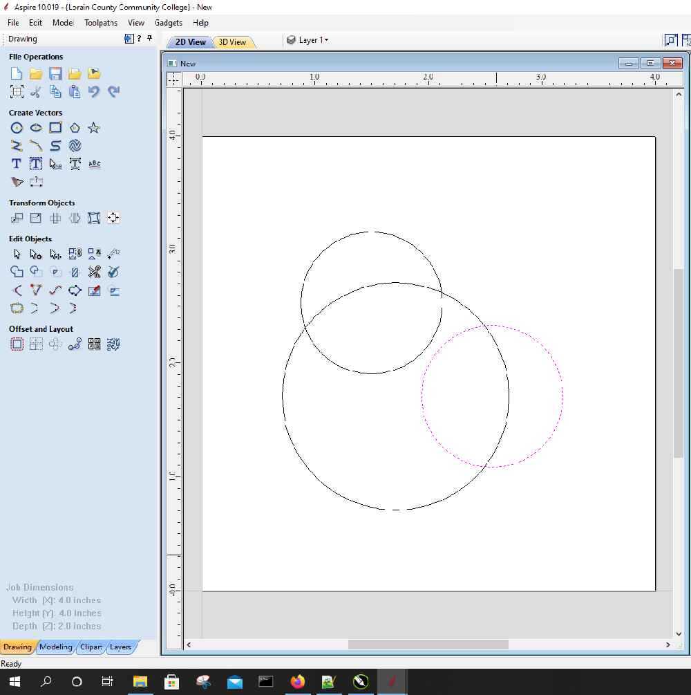
Then copy and paste a second small circle, move the circles into a position that looks like a water molecule
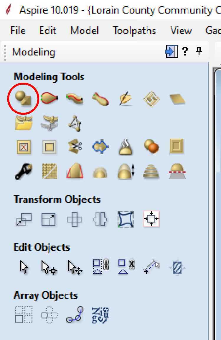
To create the 3D model, click on the Modeling tab at the bottom of the left panel
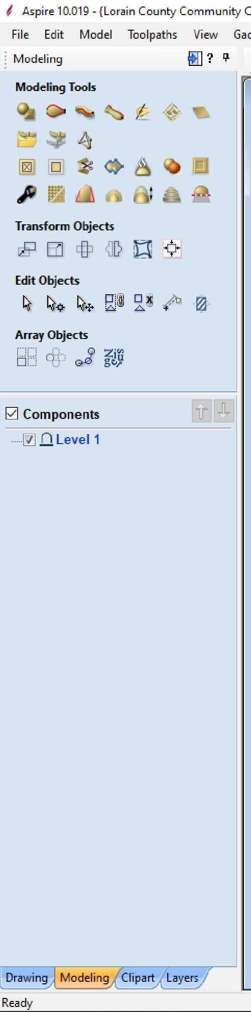
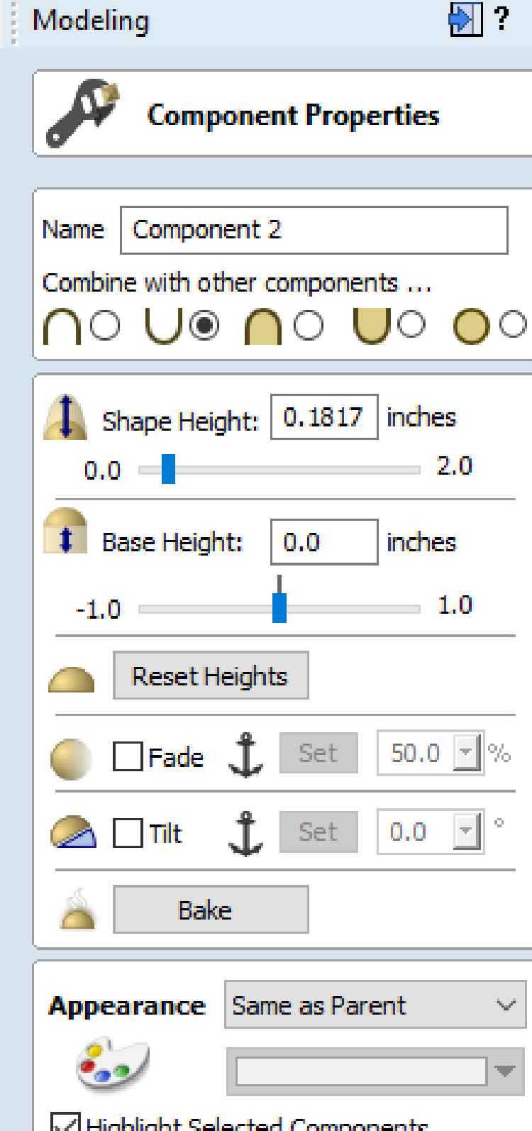
Select the create shape from vector outlines option from the modeling tools window
Which opens the Create shape tool
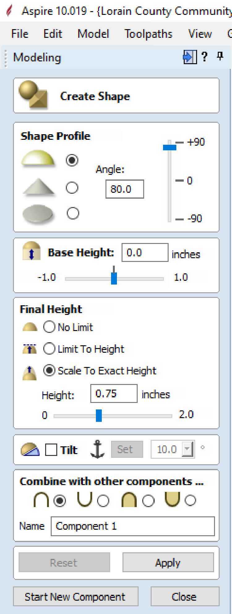
Set the parameters and select apply to see the 3D model on the right screen, these settings can be fine tuned until the model looks correct
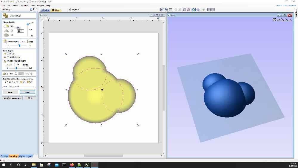
Once satisfied with the model, select start component. This will create the 3d model.
To add the letters, go back to the drawing tab (located next to the modeling tab), and chose draw text
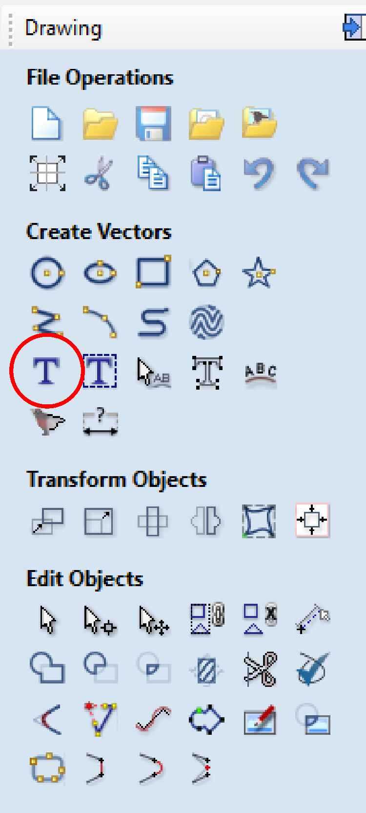
Opening the create text window
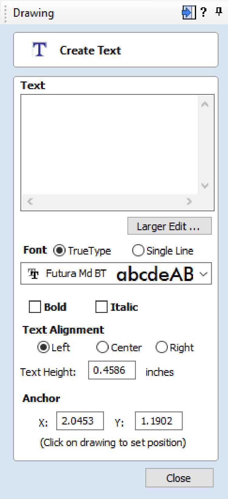
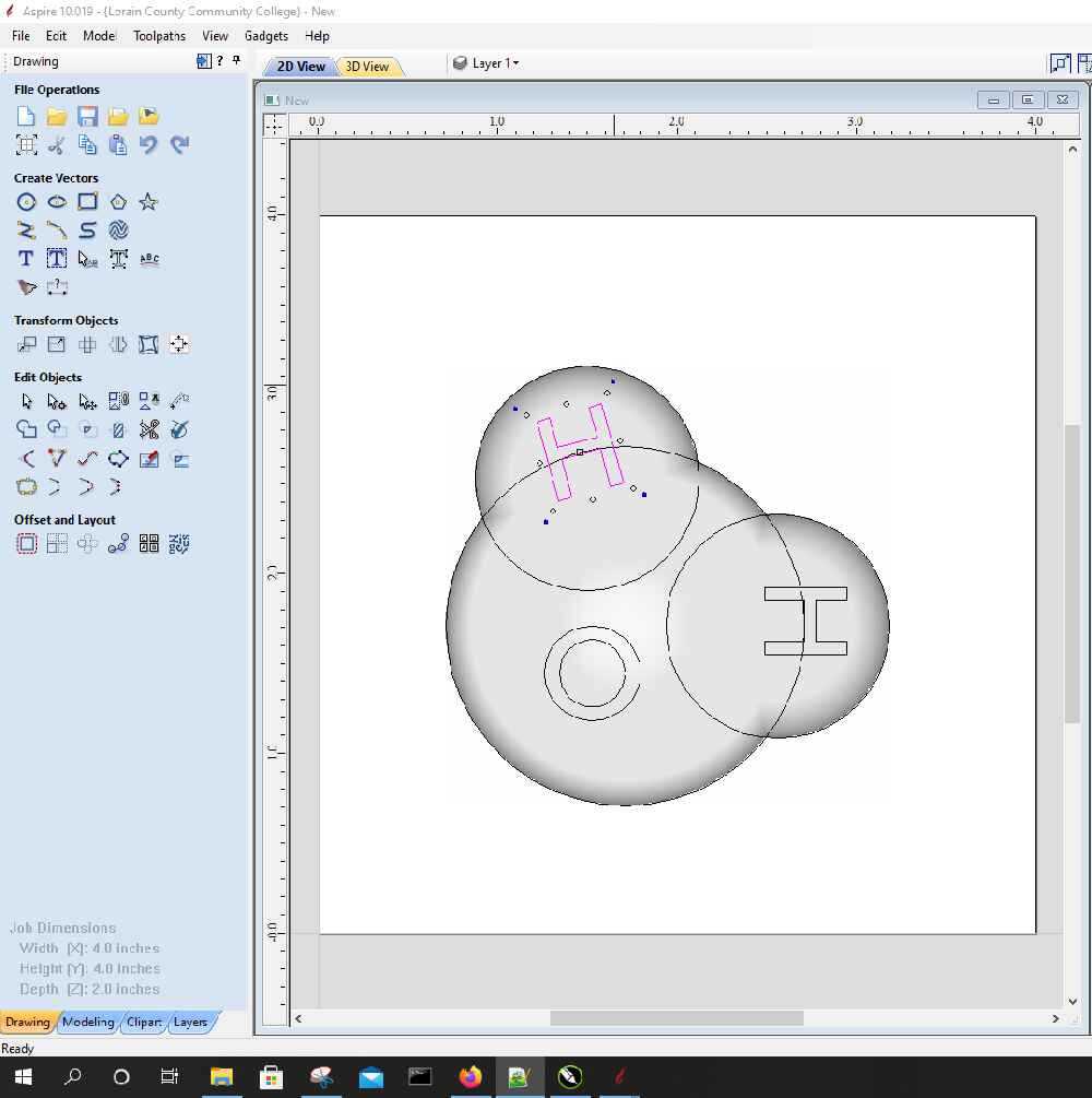
I used a capital “O” with the futura Md font. Then I positioned it on the inside the large circle
I did the same with the letter “H”, creating two of them. I then rotated them using by selecting the letter and using the outer most handle.
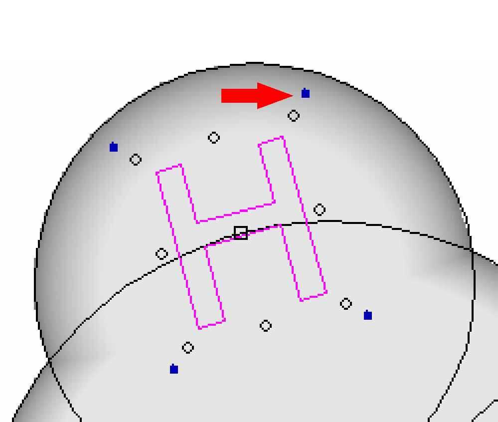
Both of the letters were rotated and positioned
I went back to the modeling tab, and created components for each of the letters. I made sure that I changed the combine with other components setting to cut and remove material, not add it. I also had to adjust the depth a few times before it looked correct
Then I was left with a 3D model
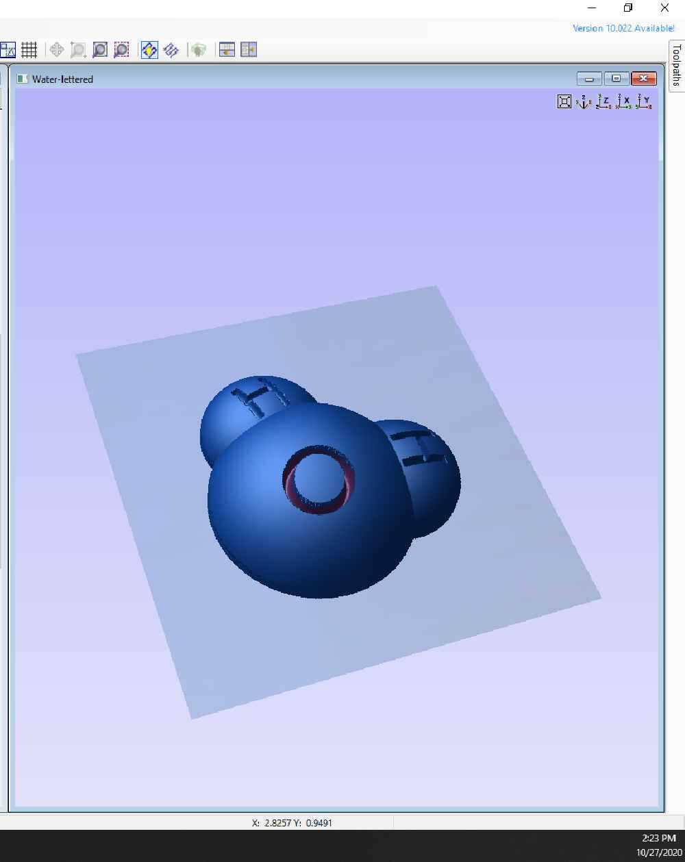
A “moat” was also needed to allow for a mold to be made. That was done by simply drawing a square large enough for the object to fit into, but with enough distance to allow a tool to remove material and leave a large enough gap to make a strong outer wall of the mold. It also had to be far enough from the edges to ensure the wax walls were strong enough as well. A 3” x 3” square gave me a 0.5” wall around the model.
Toolpaths
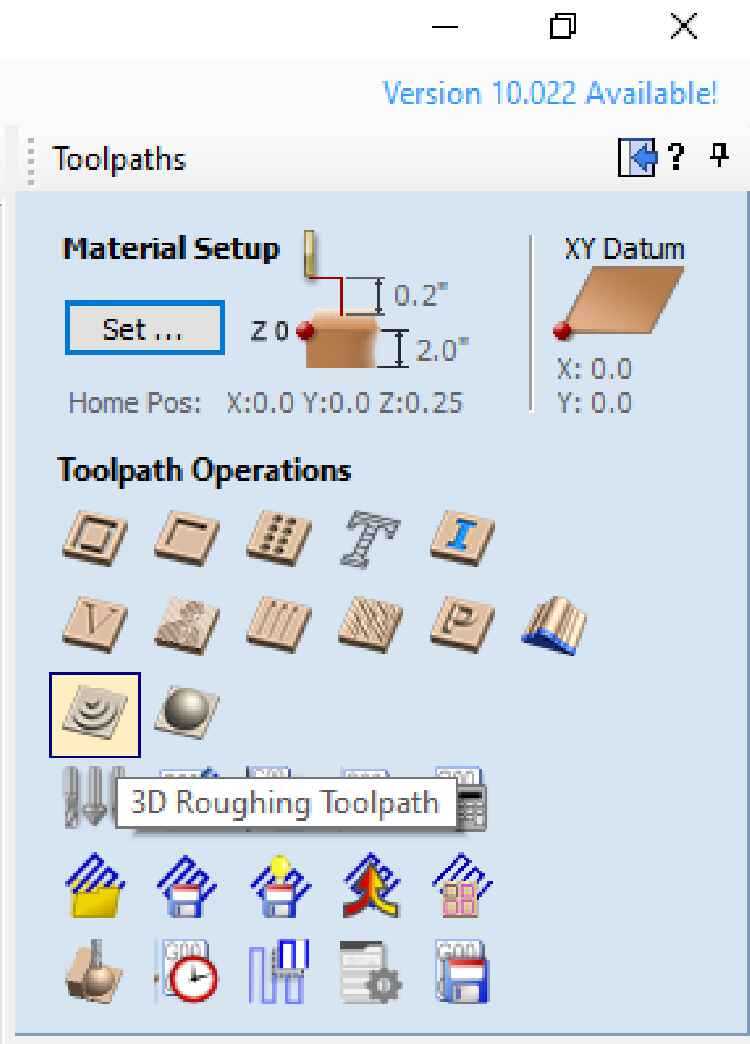
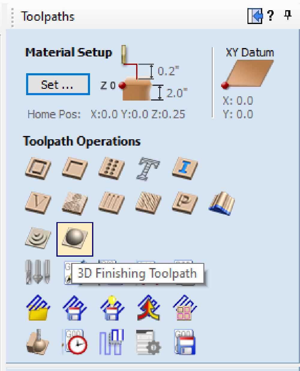
Open the toolpath window as outlined in the earlier assignment. This time, select the roughing toolpath operation
When it’s the first 3D toolpath to be created, a material setup window appears first. This is the window in which the XY datum, the z-zero plane, model position in material, rapid moves for Z is set.
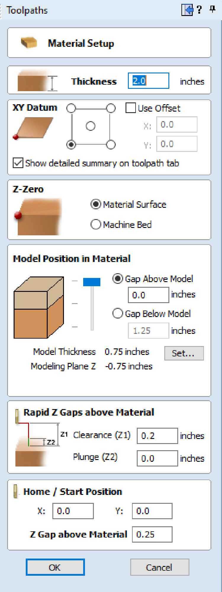
The model position in material will allow adjusting the Z position of the model
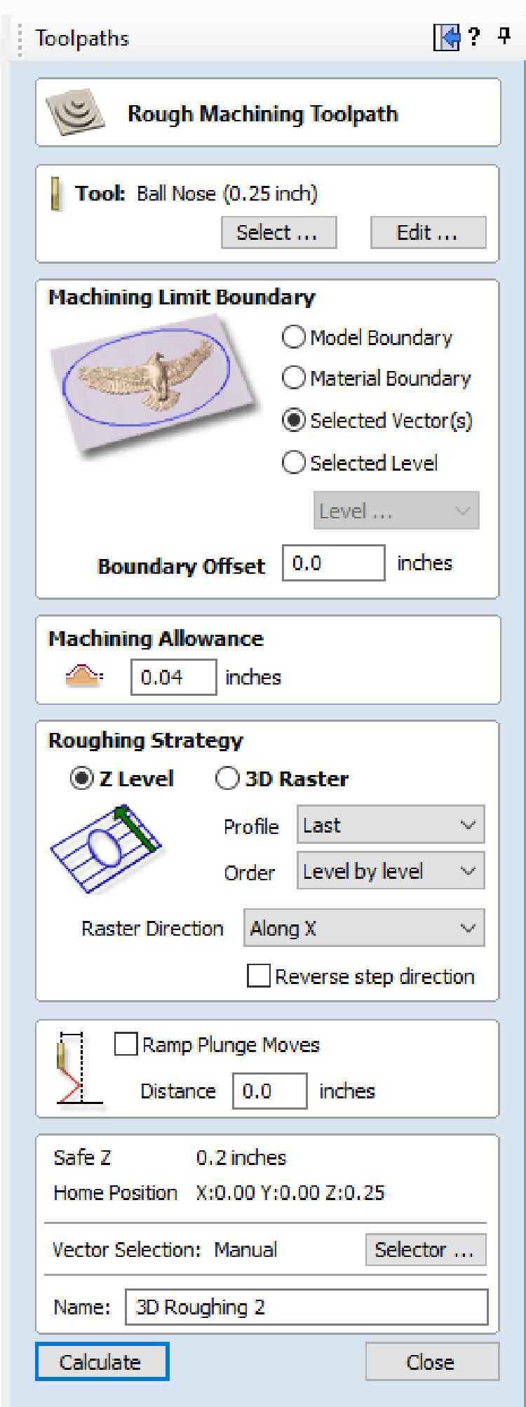
Select Ok and this will then open the roughing toolpath window
 –roughingtoolpath
The tool I selected for this operation was a 0.25” ball nose endmill. I used the same feeds and speeds calculator as before
I ended up with a spindle speed of 4000 RPM, a feed rate of 100 in/min, and a plunge rate of 50 in/min
 –quarterendmill
With that set, I adjusted the rest of the settings. The machining limit boundary was changed to ‘selected vector’, making sure that the box drawn earlier was selected in the drawing window. Machining allowance was left at its default, and the roughing strategy was Z-level. This will basically make steps to rough in the shape
Select calculate and a preview window will appear, just as in the previous assignment. Preview the visible toolpath to get an idea of what it will look like
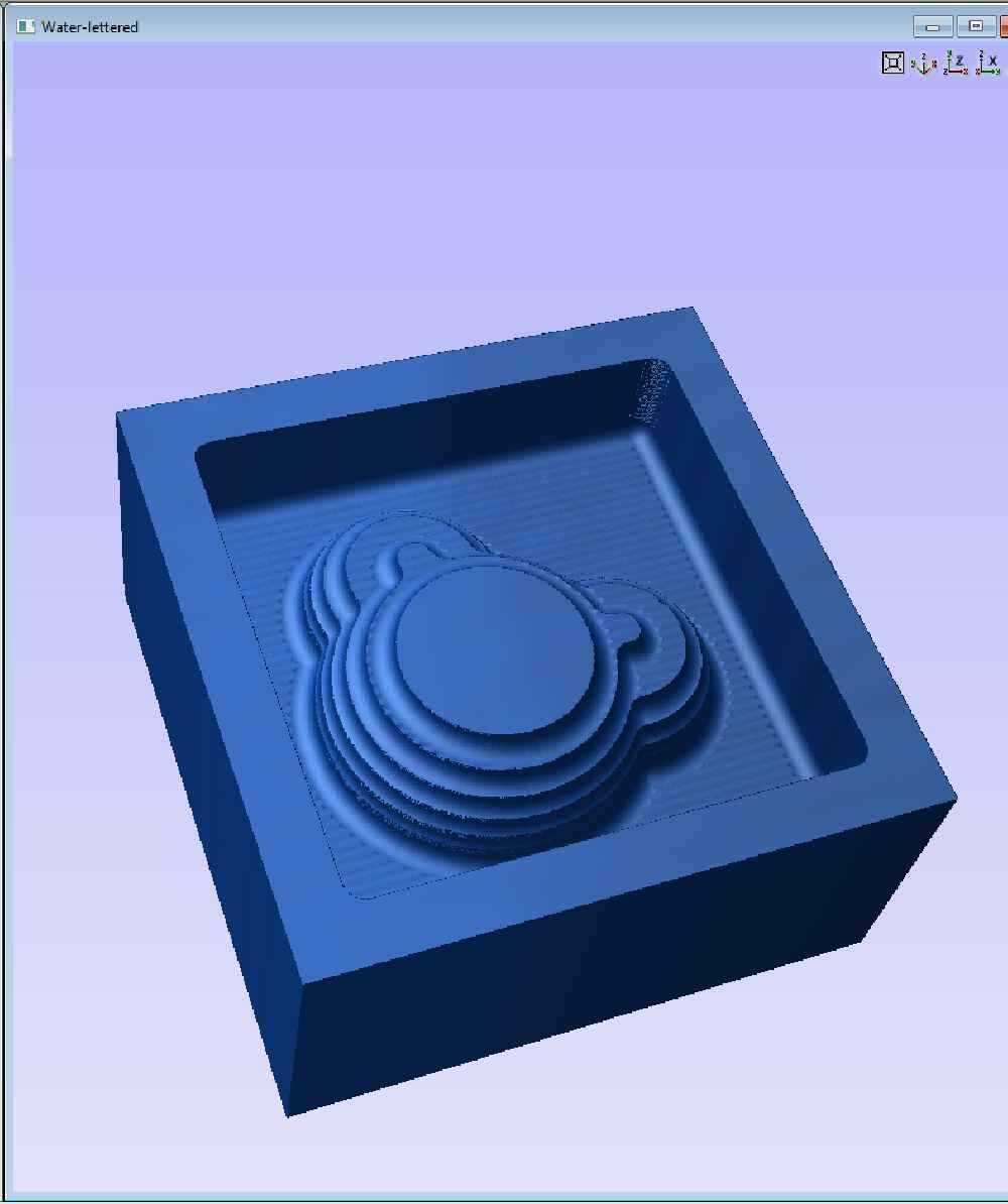
That looks good, next is to add the finishing path by selecting the finishing toolpath operation
This opens the finishing toolpath window

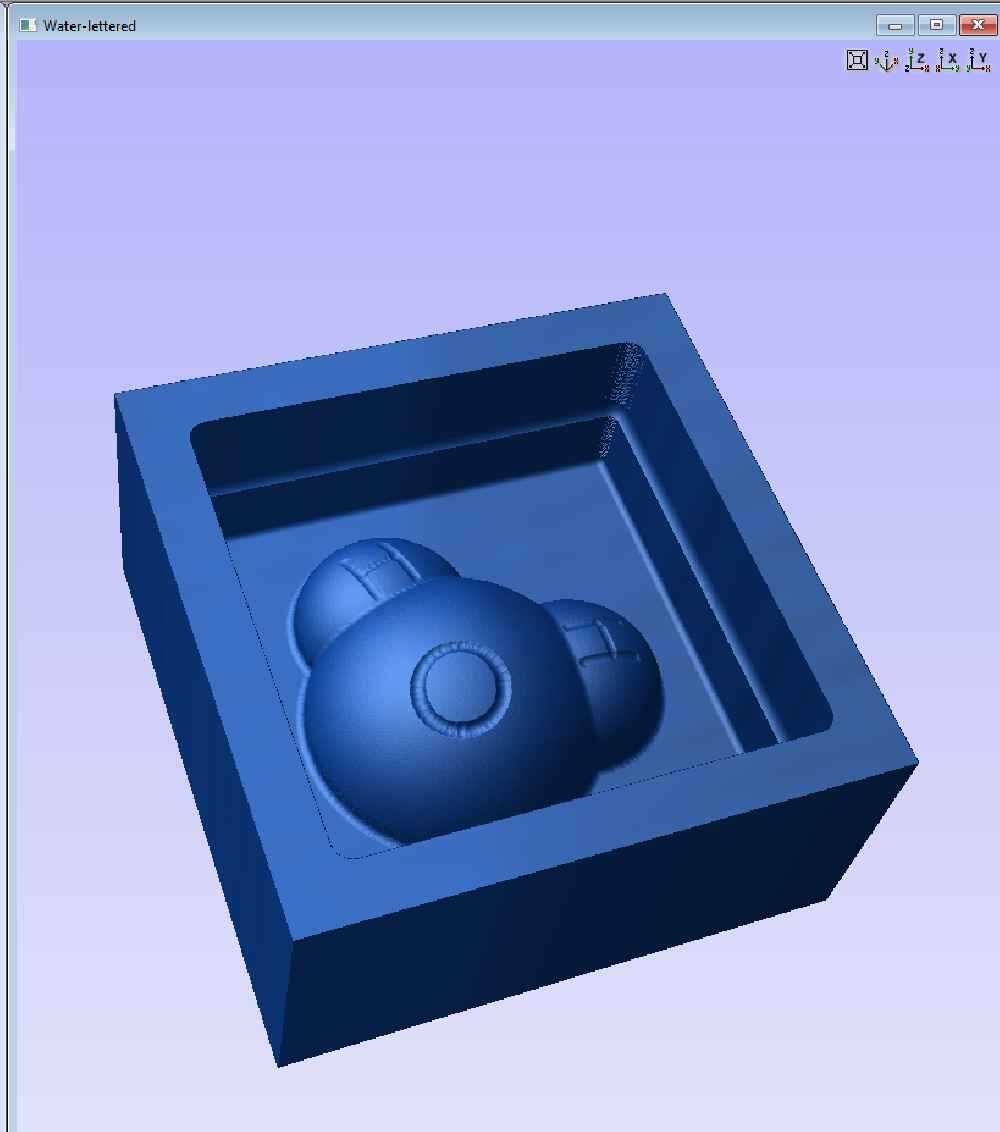
I went with a 0.125” ballnose endmill for this operation. Using the calculator, the tool has a spindle speed of 14000 RPM, a feed rate of 50in/min, and a plunge rate of 20in/min I again set the machining limit boundary to ‘selected vectors’ and ensured the box was selected. The area machine strategy was set to raster. This will move the tool back and forth along X and Y, while also moving the Z.
Select calculate and preview the the toolpath
I then followed the same procedure for saving the toolpath for our Velocity CNC.
How it was made
Milling
I’ve previously documented the process of setting up the Velocity CNC, and loading and running the code. I’ll document some of the highlights of the milling process
I used the plywood board the wax was adhered to as a way to secure it to the spoilboard using screws
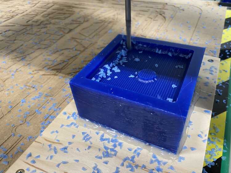
The roughing process
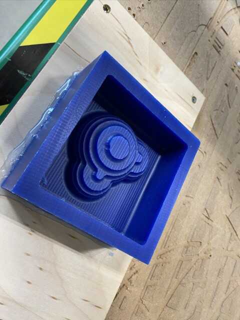
Roughing complete
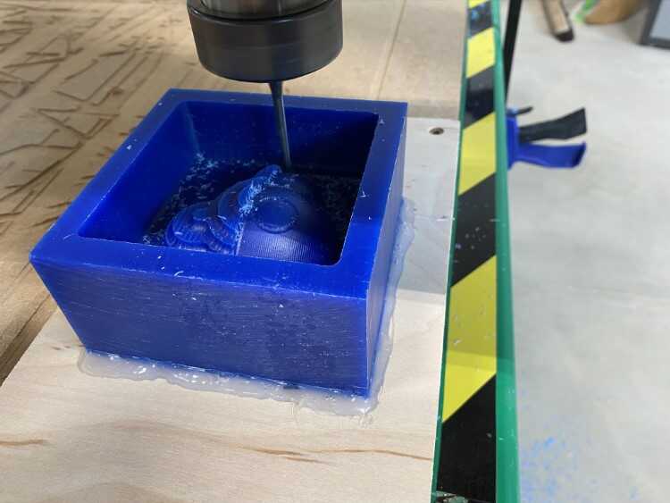
The finishing process
Finishing complete
–video
Making the mold
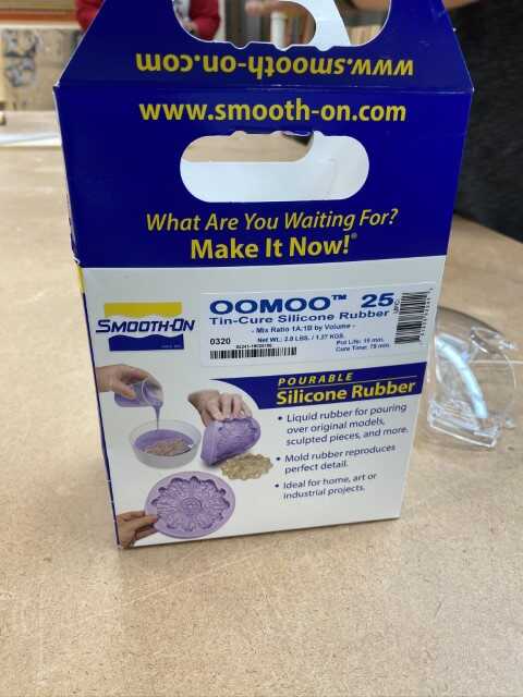
For the first attempt to create a mold, I used OOMOO 25 silicone rubber
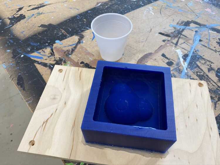
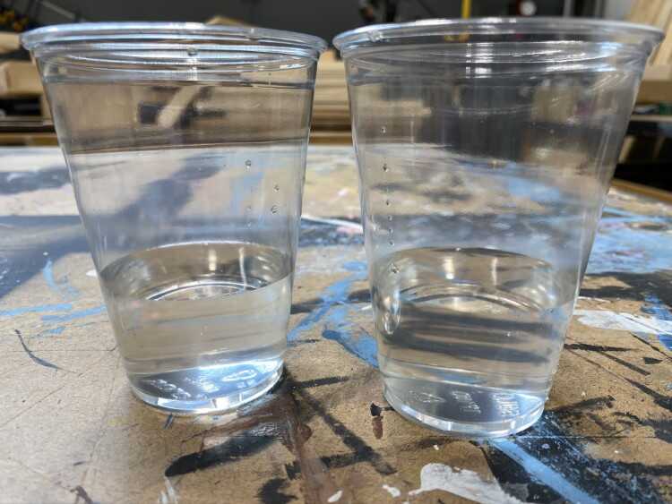
The directions state that the two parts are mixed in equal proportions by volume. To ensure enough was mixed, I figured out the volume by filling the mold with water and pouring it into a clear plastic cup
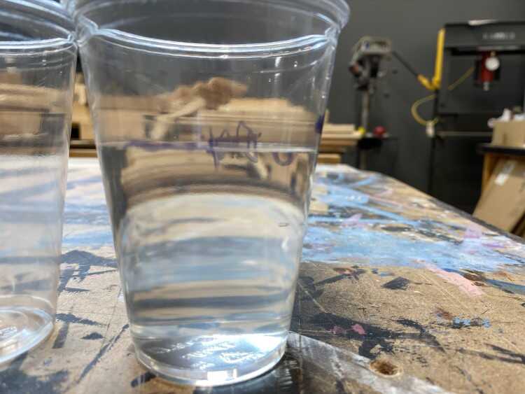
I then divided that equally between two clear plastic cups
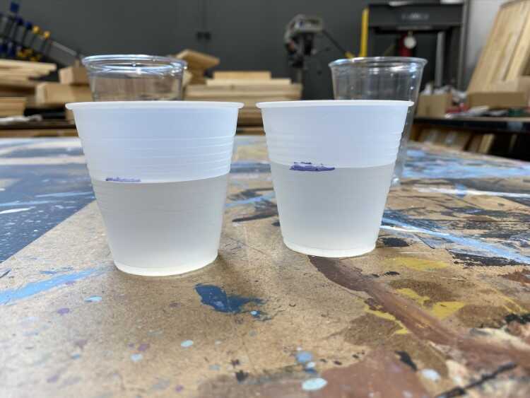
For easier mixing, the water was then transferred to smaller cups and a line was drawn to indicate a fill line
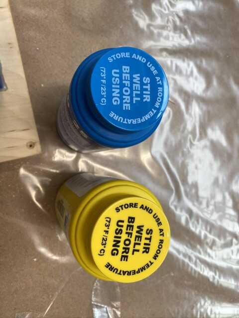
The directions and the lids of the two parts indicate that both should be mixed will in their respective containers before mixing together
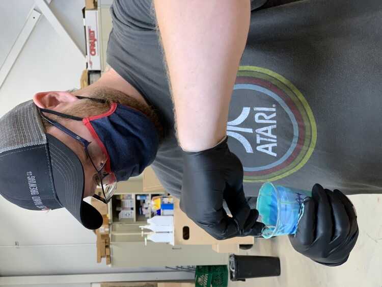
Each container was mixed with a wooded stir stick for roughly five minutes, being sure to not incorporate any air bubbles and moving in a figure-8 pattern. Once each part was mixed well, they were poured into the two cups
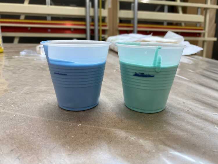
Slightly above fill line, but in equal amounts
Those were then slowly transfered to a larger plastic mixing cup, being poured slowly to avoid air bubbles
![]()
![]()
Then they were mixed, and mixed, and mixed some more. Again, using a figure-8 motion and trying to not incorporate air bubbles
As it was being mixed, the silicone started to firm up and became very difficult to stir.
Next, was to fill the mold

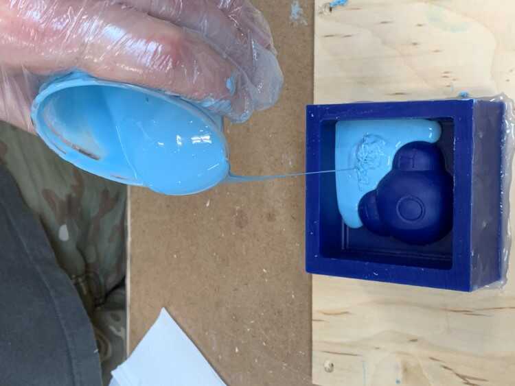
The goal here was to start at the deepest point in the mold cavity and let the silicone fill the cavity, surrounding the model
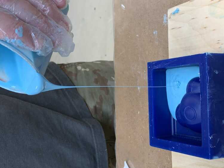
Pouring from about 12 inches above the mold allowed for a very fine stream. The theory here is that would separate any bubbles that got trapped in the mixing process
The viscosity of the silicone was extremely high, so the pouring process was slow and difficult. I tried to smooth the top out as best I could with a stirring stick

And the cavity was filled completely
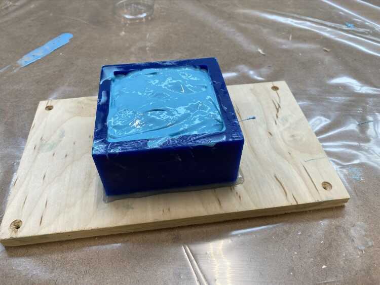
The cure time for OOMOO 25 is 75 minutes, but I let it set for a few hours. After which I removed the silicone mold
The end result wasn’t good. There were still a lot of bubbles and air pockets. Further research suggested using a vacuum de-gasser during the curing process. The material itself may have passed it’s shelf life as well.
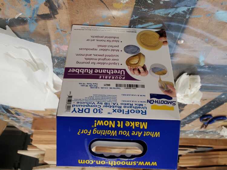
I decided to purchase my own material and try again, this time using ReoFlex 30, a urethane rubber. It has the same 1:1 mixing ratio as the OOMOO25, but its viscosity rating is 1500 cps (compared to OOMOO25 at 4250 cps). The only draw back is the cure time is 16 hours.
I followed the same process as I did with the OOMOO 25. I mixed the containers, poured equal amounts, and mixed them together
Before I poured the ReoFlex into the mold, I had to spray a release agent onto the wax mold
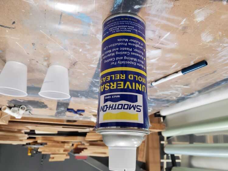
I sprayed a very thin coat onto the mold
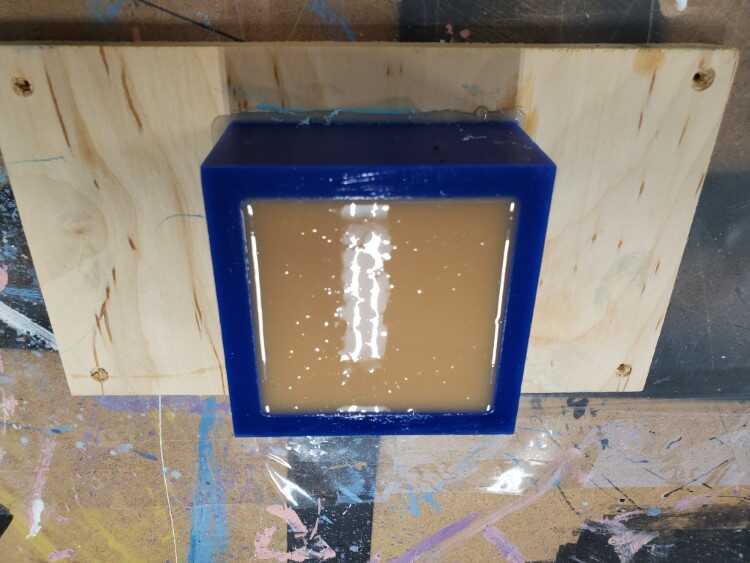
And poured it in, same as before
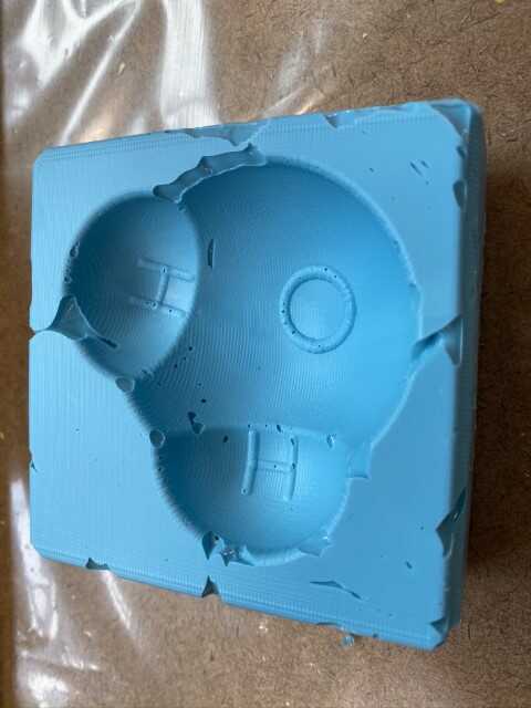
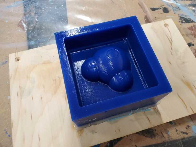
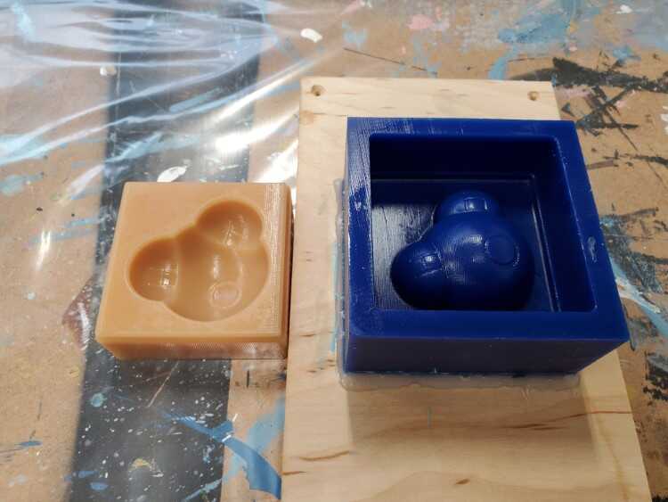
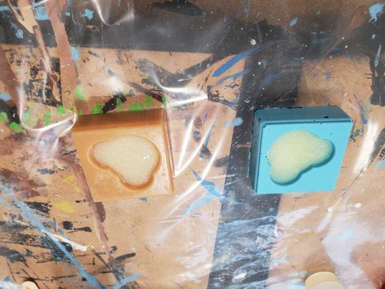
The next day, I had to use a thin scrapper to release the ReoFlex
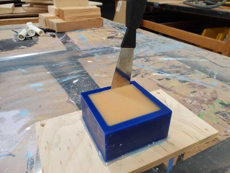
But the end result was much better
Casting the plastic
To make the casting, I used Smooth-Cast 325. I’ve documented it’s properties and some insights from the MDS on the group page.
This material is also a 1:1 mix ratio, which makes things easier.
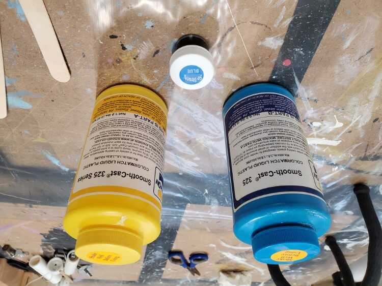
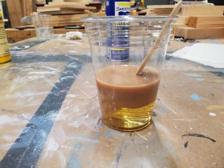
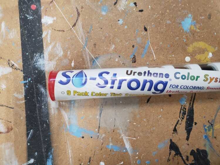
I also decided to use the So-strong urethane coloring system to tint the plastic blue
First, I mixed the color into Part B of the Smooth-Cast and made sure is was well mixed. Following the same procedures as before, I mixed parts A and B together and poured it into the ReoFlex mold
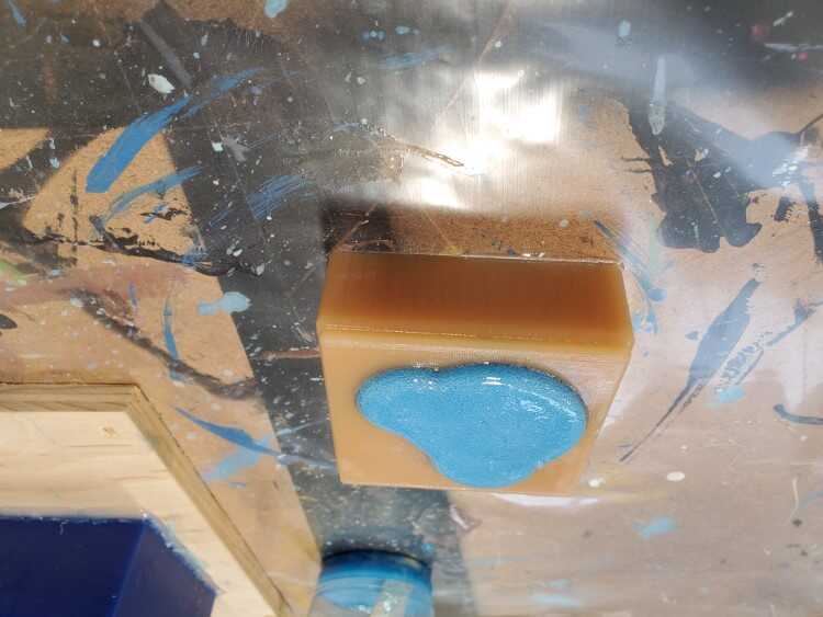
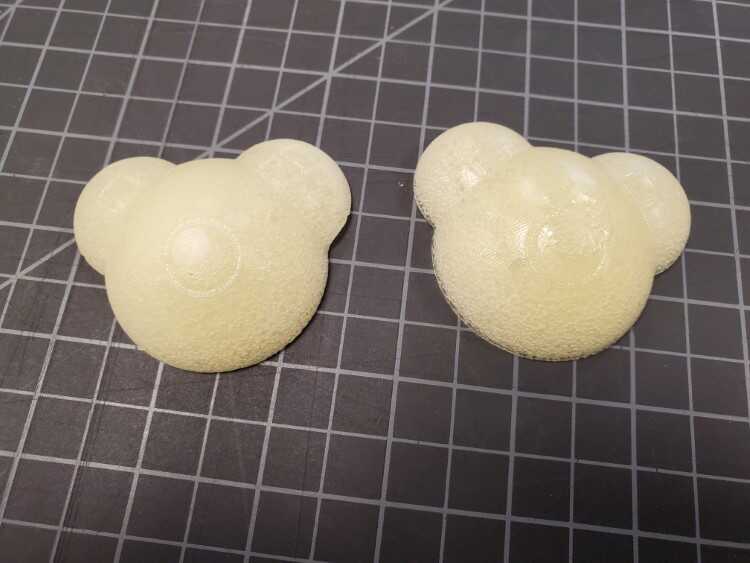
A lot of bubbles caused the casting to expand
After a cure time of 15 minutes, I pulled my casting out

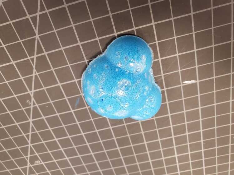
Issues
One of the biggest issues I had was bubbles forming in the Smooth-Cast. I tried re-casting without the color agent as well as using the silicone mold.
The results were about the same
After doing some research, moisture seems to be the culprit. First, the Smooth-cast I was using had already been open, so it most likely absorbed moisture during that time. Another possibility is the stir stick I used. Using a wood stir stick can introduce moisture while mixing. The urethane will pull the moisture out of the wood, causing air bubbles.
Files

This work is licensed under a Creative Commons Attribution-NonCommercial-ShareAlike 4.0 International License.