18. Wildcard week
Vacuum Forming
Design
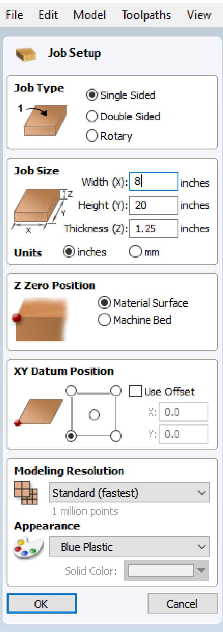
I used Vectric Aspire to design the buck I’ll be using with the vacuum former to create a mold
The process is very similar to a previous week’s assignment, but I’ll explain the differences on this page
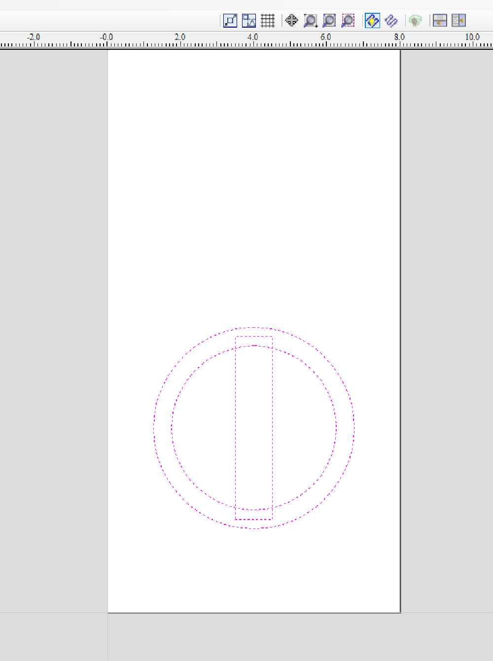
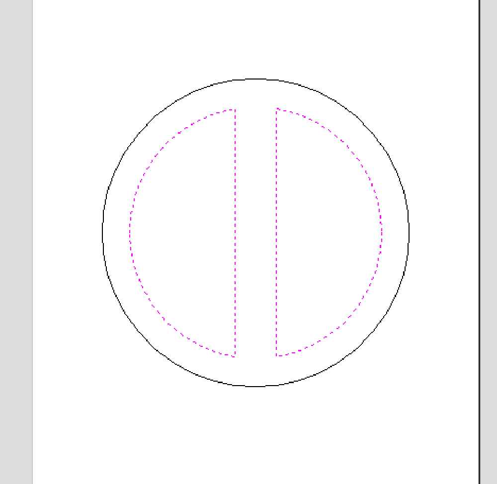
Using the CAD tools, I drew 5.5” circle, 4.5” circle, and a 0.75” x 5” rectangle and centered them all using the Align Selected Objects tool

Then I chose the center on last vector option. In this case, the last selected vector doesn’t matter as were centering everything
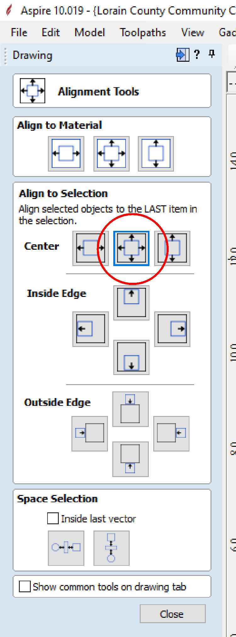
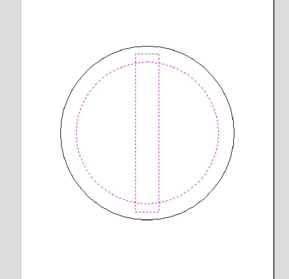
Which aligned all of the shapes
To merge the inner vector into a single object, select the inner circle and rectangle
The I chose the subtract tool
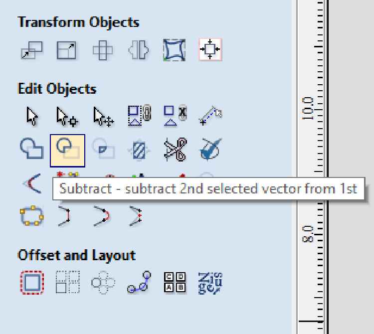 This removes overlapping vectors and creates a new vector
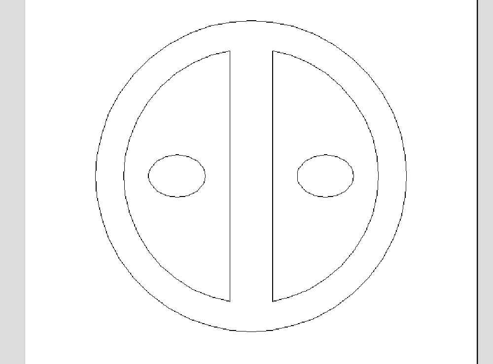
Create two ellipses 1” x .075” and position inside of the new half circle shapes
Toolpaths
The toolpathing process used here is basically the same as the processed used during the Computer controlled machining assignment:
The first thing I want to do is create a pocket from the half circle shapes, while leaving the inner ellipses as islands
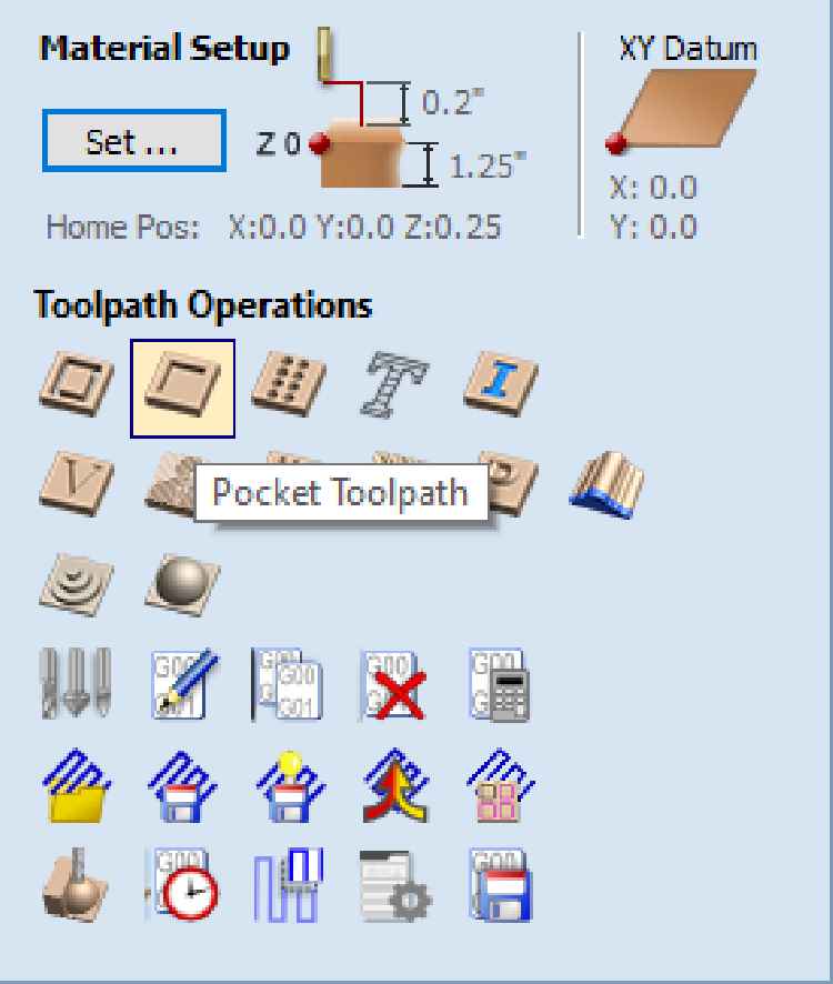
Opens the pocket tool window
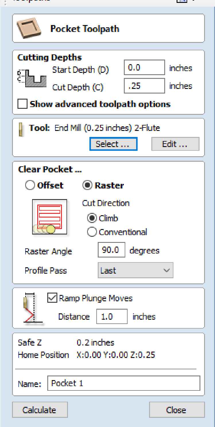
Selected a 0.25” 2-Flute end mill
I determined the RPM and feed rate from the manufactures website
I’m using Renshape 440, so I used their provided settings to calculate my own. I’m using an RPM of 6700 and a feedrate of 200in/min
Before calculating the pocket, I had to make sure the correct vectors were selected

The center ellipses will be left as islands while the rest of the half-circle shape will be removed
Click calculate the toolpath just as before

The profile cut was set up the same way, with the same settings. Only selecting the outer more vectors

Then I saved the toolpaths for the Velocity just as before and performed the machining operation on the Velocity CNC
Machining
The machining process isn’t any different than previously documented. The material is mounted to the CNC router using screws. I pre-drilled the holes for the screws, and also placed them in such a way that the cutting tool won’t hit them
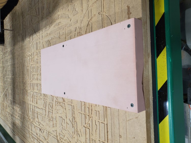
I installed the end-mill, homed the machine, set the program zeros, and opened the g-code file. With everything set, I started cutting
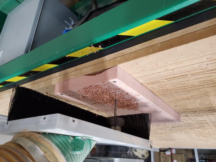
After only about five minutes, the milling was complete
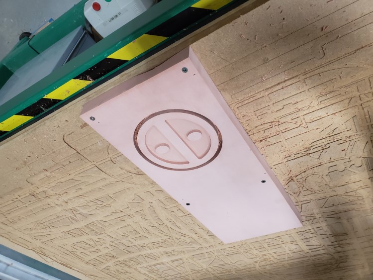
I pulled the material off the CNC and attempted to remove the buck, but ran into some issues (see Issues section). I eventually removed and cleaned it
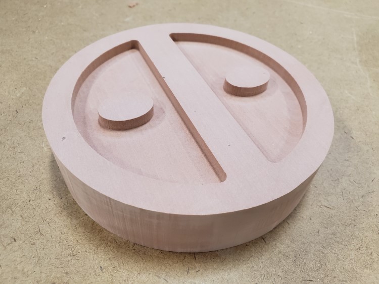
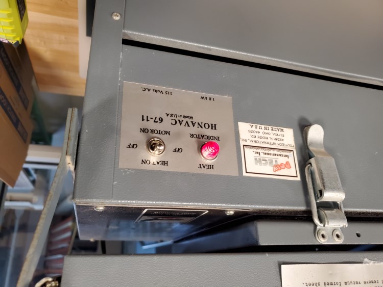
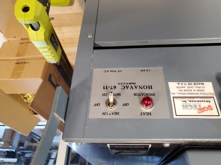
Vacuum Forming
I’m using our in-house vacuum former and 0.20” PETG
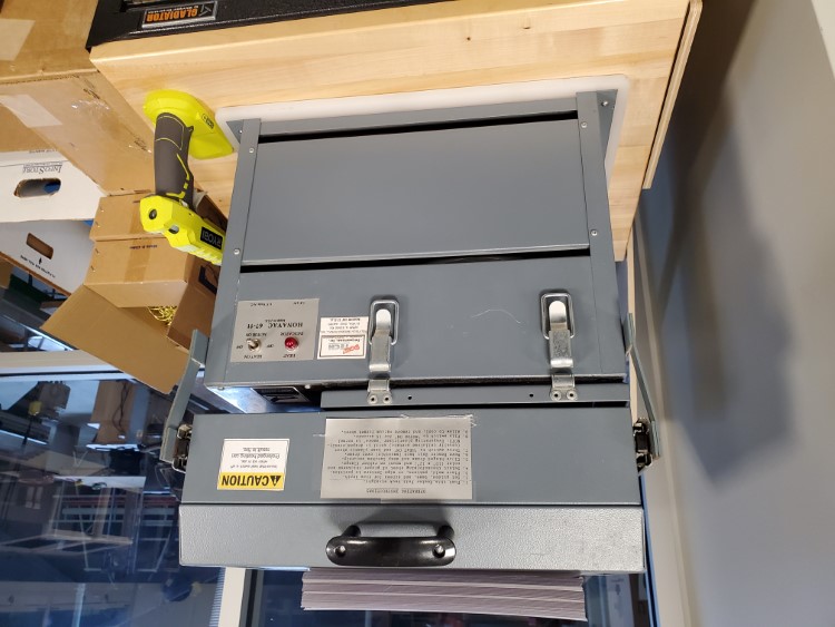
First step was to slide back the top (which contains the heating element), and open the frame that holds the PETG sheet. Then place the buck inside
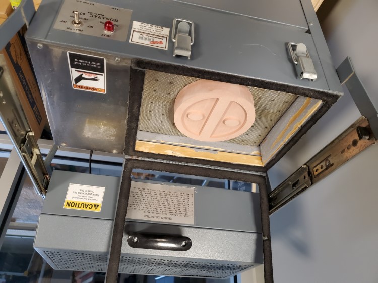
Then lay the PETG sheet onto the black seal, close the frame, and latch it tight. This particular vacuum former is designed for sheet that are 10” x 12” in size
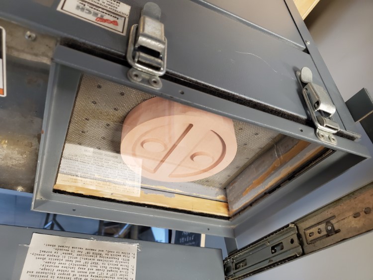
Slide the lid over the sheet and turn on the heating elements
It take a few minutes for the elements to heat and soften the plastic sheet. You can slide the top back carefully and look at the PETG sheet. Once it’s starting to sag, switch to the vacuum
The vacuum will power on and remove the air, pulling the softened sheet over the buck. This only takes a few seconds
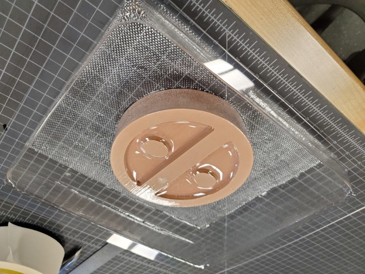
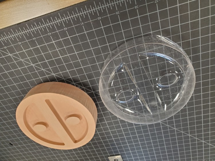
I removed the buck and was left with a mold (see Issues section for some things that were encountered on this step)
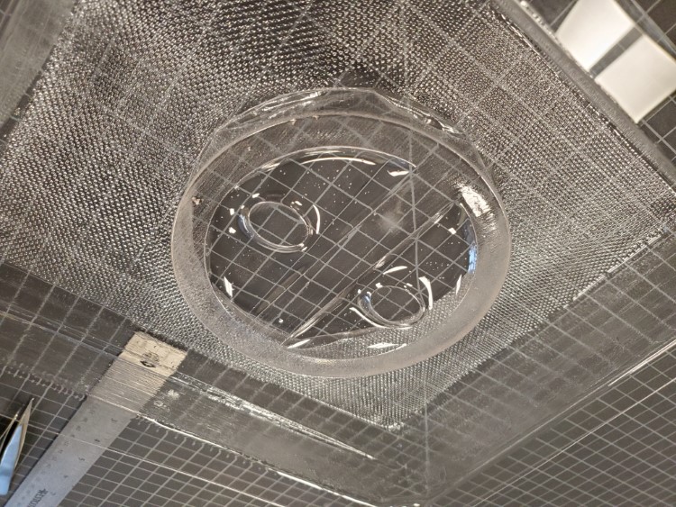
And the hero shot
Issues
Material chips got stuck when performing the profile cut. I had to persuade it to break free. A possible solution to this would be to use an upcut end mill to evacuate the chips as it cuts. The buck wouldn’t release from the PETG sheet after the vacuum form. To solve this, a draft angle would be added. Basically, the side would taper inward from bottom to top, allowing the buck to be removed easily. The last issue I encounted was the inner detail didn’t show very well. I think adding some small holes to allow more air to pull through the material would help this problem.
Files

This work is licensed under a Creative Commons Attribution-NonCommercial-ShareAlike 4.0 International License.