9. Embedded programming
ATtiny1614 Datasheet
Much of the work I did for this board can be found on the Electronics Design page. Here I’ll focus on the programming aspect of the board.
I chose the Attiny1614 as it is a modern chip that supports UDPI programming. I wasn’t sure about it’s clock speed or the on-board flash memory. To find that information, I looked at the chips datasheet.
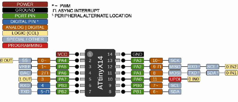
At first glance, trying to read through the datasheet seemed daunting. However, I tried to just get the information most relevant to the upcoming projects. First, was how fast can it run and how much memory does the chip have. I found that it can run up to 20MHz and 16KB of in-system flash memory. That will be more that enough to run the LED’s for my final project. Second, was to figure out the pinout of the chip itself. I needed to know what pins I can use for the two LEDS and push buttons.
Programming the board
Arduino IDE
To program the board, I first needed to install pyupdi. I opened the command prompt and installed the program using the following command:
pip install intelhex pylint pyserial
With that installed, I used the Arduino IDE to write the program and generate the hex file pyupdi needs for the install process
By default, the Attiny1614 chip isn’t supported by the IDE, but they can be added. These were found on the following repository:
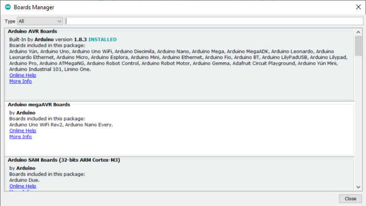
Or, in the IDE, they can be added via the boards manager.
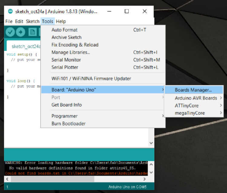
Tools=>Board=>Board manager
Search for megaTinyCore and install
This will allow the code to be complied for the ATTiny1614 or any other boards in that family.
For the program, I started with the provided “echo” code for the ATtiny412
Using that as a base, and the knowledge I learned out the pinout of the ATTiny1614, I modified the code to blink the two LED’s I added to the board from the Electronics design week. I connected the LEDS to pins PA4 and PA5, which equates to pins 0 and 1 in the Arduino IDE.
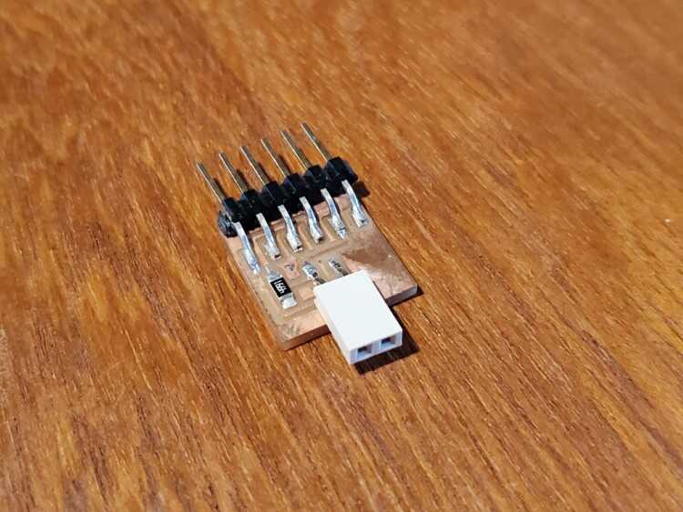
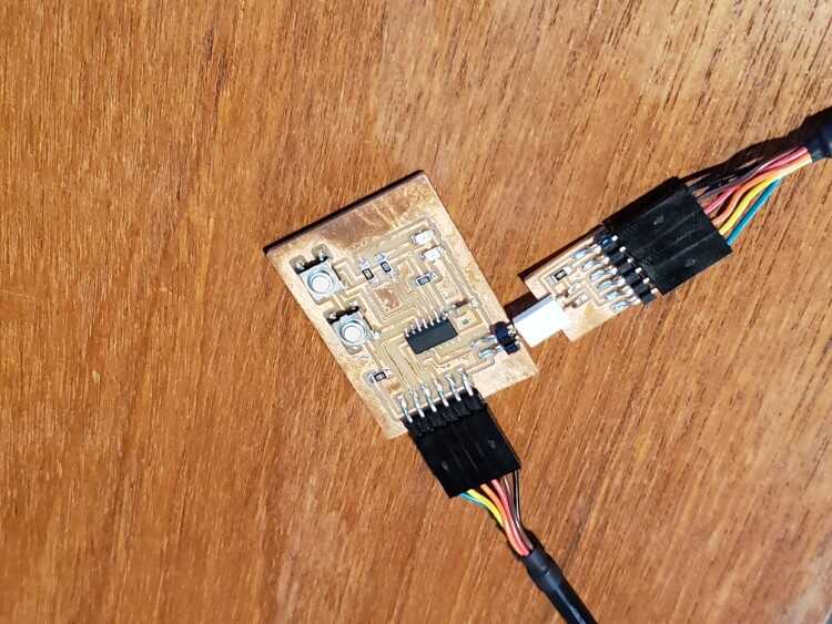
To load the program, I used an FTDI cable and the hello.serial-UPDI adapter
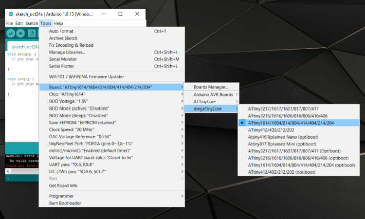
The board had to be changed from the Uno to the ATTiny1614 in the Arduino IDE to allow me to compile the code. To do this, go to Tools=>Boards=>megaTinyCore=>ATtiny1614
This also allowed me to see which COM port the board is connected to, and made a note of it.
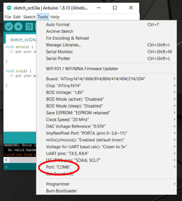
COM6
I verified the code would compile and attempted to load it to the board using pyupdi. The pyupdi code requires a hex file. Finding the hex file can be difficult and have a long extension name. I found an easy tutorial describing how to change the default storage location for the hex files.
I moved the location to the main root directory, making the file easy to find and giving it a short extension name
Opening the command prompt again, I entered the following command:
pyupdi.py -d tiny412 -c COM6 -b 57600 -f c:\blink.t1614.ino.hex -v
I received multiple errors stating that it “could not open port”. After some research, I found that Windows won’t open the port directly using the python command. Luckily, there was a tutorial on how to do just that from the same website discussing changing the hex file location:
After following the tutorial and opening the port, I ran the script again and the file loaded. The code alternates the two LEDs once every half second
Video
Linux & gcc-avr
For an attempt at a different programing environment, I used AVRdude, AVRgcc and a makefile on Linux. I’m using one of my modular ATtiny84 boards that I designed for my final project and the TinyISP programmer I manufactured for the Electronics Production assignment
Using the header pins, I connected a ground wire to the cathode side of a blue LED and connected the anode to the header pin connected to pin 6 on the ATtiny84. This equates to pin 7 on the Arduino IDE and port PA7. The goal was to write a simple blink code in standard C with .c extension. Having not done this before, I referenced some of the code provided on the Fab Academy website. Looking at the datasheet, I found the data direction register for PA7. The direction was set to act as an output. Setting the while loop to 1 causes it to run infinitely. Within that loop, PORTA = 0x80 sets PA7 high. There is then a 1 second delay, then PORTA = 0x00 sets the pin back to low. Then another 1 second delay and it repeats.
#include <avr/io.h>    // this includes the information about the avr Atmel microcontrollers
#include <util/delay.h>  //  delay header

int main()  // main function must have
{// this bracket opens main

    DDRA = 0x80;  // sets the data direction register for port a or PA7 it is bitwise set

    CLKPR = (1 << CLKPCE);
    CLKPR = (0 << CLKPS3) | (0 << CLKPS2) | (0 << CLKPS1) | (0 << CLKPS0);

    while (1) // starts a while loop in this case it is a forever loop
    {// anything between here and the other bracket is in the loop.

        PORTA = 0x80;   // turns on one pin
        _delay_ms(1000);  // waits 1 second
        PORTA = 0x00;//   turns off all of PORTA
        _delay_ms(1000);//  waits 1 second
    }


    return 0;// need this because of int main

}  // this bracket closes main
Next, I used a makefile to compile it. I used the makefile from Neil’s hello44 project. The ATtiny84 is the same as the ATtiny44, just with more memory, so I figured it should work. I did have to make some changes to reflect my file name and set the correct chip
PROJECT=84LED
SOURCES=$(PROJECT).c
MMCU=attiny84
F_CPU = 20000000

CFLAGS=-mmcu=$(MMCU) -Wall -Os -DF_CPU=$(F_CPU)

$(PROJECT).hex: $(PROJECT).out
    avr-objcopy -O ihex $(PROJECT).out $(PROJECT).c.hex;\
    avr-size --mcu=$(MMCU) --format=avr $(PROJECT).out

$(PROJECT).out: $(SOURCES)
    avr-gcc $(CFLAGS) -I./ -o $(PROJECT).out $(SOURCES)

program-bsd: $(PROJECT).hex
    avrdude -p t44 -c bsd -U flash:w:$(PROJECT).c.hex

program-dasa: $(PROJECT).hex
    avrdude -p t44 -P /dev/ttyUSB0 -c dasa -U flash:w:$(PROJECT).c.hex

program-avrisp2: $(PROJECT).hex
    avrdude -p t44 -P usb -c avrisp2 -U flash:w:$(PROJECT).c.hex

program-avrisp2-fuses: $(PROJECT).hex
    avrdude -p t44 -P usb -c avrisp2 -U lfuse:w:0x5E:m

program-usbtiny: $(PROJECT).hex
    avrdude -p t84 -P usb -c usbtiny -U flash:w:$(PROJECT).c.hex

program-usbtiny-fuses: $(PROJECT).hex
    avrdude -p t44 -P usb -c usbtiny -U lfuse:w:0x5E:m

program-dragon: $(PROJECT).hex
    avrdude -p t44 -P usb -c dragon_isp -U flash:w:$(PROJECT).c.hex
I was using the usbtiny as my programmer, so I had to change the chip to t84, as well as set the MMCU to attiny84
With both of those files now saved to the same folder, I navigated to it using the command line-windows-mac-linux
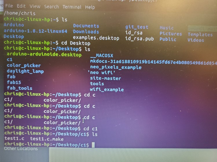
I then had to compile the code and generate a hex file. That was done by using the following command:
make -f 84LED.make
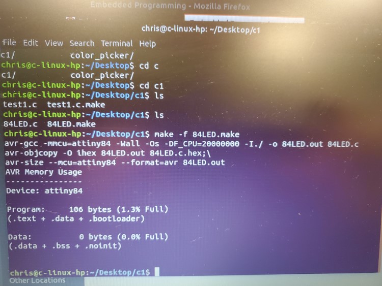
Success
The last step was to take the hex file and program the board with the usbtiny programmer. This was done with the following command:
make -f 84LED.make program-usbtiny
program-usbtiny calls the longer command line from the makefile. Much more efficient.
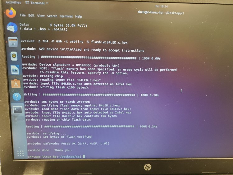
The file was loaded on the the modular ATtiny84 board, setting the fuses in the process.
I checked my hardware and found the LED was blinking
Video
Files

This work is licensed under a Creative Commons Attribution-NonCommercial-ShareAlike 4.0 International License.