16. Interface and application programming
How it was made
The plan is to design a simple GUI that will let me control color mixing and RGB LED. This needs to be done in two parts; first, I’ll need to design the GUI using a python script, second I’ll need to write an Arduino code that will allow the interface to communicate with the GUI. The app Notepad++ was used to write the python script. Please note that this was done during the local lock-down, so I didn’t have access to the FabLab. I used an Arduino Uno per Neil’s approval.
I already have Python installed, so I started with the following tutorial:
There was a lot of information in that tutorial, so I looked for something a little more specific. The first tutorial I found was how to make a button to control and LED:
I learned from the video that I needed to install both pySerial and Tkinter. Looking into it further, I learned that Tkinter comes preloaded with all standard Python distributions. To install pySerial, I opened a command prompt window and entered the following code:
pip install pyserial
The first thing I did was design a simple interface with two buttons
from tkinter import *

test_gui = Tk()

ONBTN = Button(test_gui, text="ON")
OFFBTN = Button(test_gui, text="OFF")

ONBTN.grid(row=0, column=1)
OFFBTN.grid(row=1, column=1)

test_gui.mainloop()

input("Press enter to exit")
This uses Tkinter’s built in button object as well as the grid function. I made two button objects (ONBTN & OFFBTN), and placed them in a grid
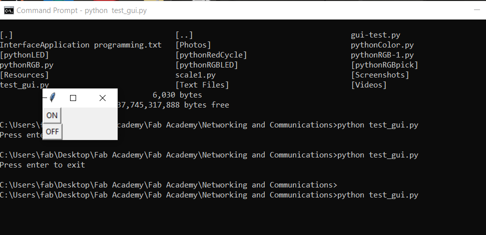
To run the file, I used the command prompt, navigated to the folder the .py file was saved in and entered the following command:
python test_gui.py
And this little window appeared
How it works
The next step was to add commands to the buttons, as well as the serial communication.
Importing serial allows me to create an object for sending and receiving data from the Arduino. It does require the proper COM port and a baud rate. Using ‘def’, I was able to create two objects (LED_OFF & LED_ON) to store the data type I want sent to the Arduino. I added that to the button object, so now, every time the OFF button is pressed, the Arduino receives a character. When the OFF button is pressed, the character b‘0’ is sent to the Arduino. The Arduino then recognizes that the serial port is available, and reads the incoming data. It interprets b‘0’ as the character 0. It then runs it through the if statements and sets the LED pin to LOW.
import serial
from tkinter import *

arduinoComms = serial.Serial('com5',9600)

def LED_OFF():
    arduinoComms.write(b'0')

def LED_ON():
    arduinoComms.write(b'1')


test_gui = Tk()

ONBTN = Button(test_gui, text="ON", command=LED_ON)
OFFBTN = Button(test_gui, text="OFF", command=LED_OFF)

ONBTN.grid(row=0, column=1)
OFFBTN.grid(row=1, column=1)

test_gui.mainloop()

input("Press enter to exit")
There has to be an Arduino sketch set up to receive that data and parse what should be done with it.
char serialData; //creates a data type to store incomming characters from the gui

int LEDpin = 10; //Pin for blue LED

void setup()
{
  Serial.begin(9600); //Setting the correct BAUD rate
  pinMode(LEDpin, OUTPUT); //Setting the pin to an output
}

void loop()
{
  if (Serial.available() > 0)
  {
    serialData = Serial.read();
    Serial.print(serialData);

    if (serialData == '1')
    {
      digitalWrite(LEDpin, HIGH);
    }
    else if (serialData == '0') {
      digitalWrite(LEDpin, LOW);
    }
  }
}
Simple but effective
ATtiny84 modular board
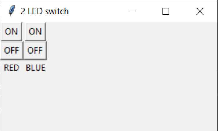
Now that I got that working on an Arduino, the next step was to get something similar working on a board I made. I chose the ATtiny84 modular board I designed for this assignment as well. I added a second LED into the circuit. The plan was to have a GUI that would allow me to have two separate on and off buttons, a label indicating the color it controls, and a title in the window. After reading more about Tkinter and it’s object based programming, I came up with this code:
#Control two LED's on an ATtiny84 with a graphical user interface written in python
#by Christopher Leon

import serial
from tkinter import *

t84data = serial.Serial('com6',9600) #Match that of the Comm port of the ATtiny84 modular board

#Objects for sending the commands over serial

def RLED_OFF():
    t84data.write(b'0')

def RLED_ON():
    t84data.write(b'1')

def BLED_OFF():
    t84data.write(b'2')

def BLED_ON():
    t84data.write(b'3')


t84_2LED = Tk()

t84_2LED.geometry('300x150+200+300') #creates a window of a defined size for the GUI
t84_2LED.title('2 LED switch') #Title on the top of the window

#These are button widgets that send defined commands
RONBTN = Button(t84_2LED, text="ON", command=RLED_ON)
ROFFBTN = Button(t84_2LED, text="OFF", command=RLED_OFF)

BONBTN = Button(t84_2LED, text="ON", command=BLED_ON)
BOFFBTN = Button(t84_2LED, text="OFF", command=BLED_OFF)

#Use the built-in grid feature to lay out the buttons

RONBTN.grid(row=0, column=2)
ROFFBTN.grid(row=1, column=2)
RLABEL = Label(text='RED').grid(row=2, column=2) #Label object to indicate which color is being controlled

BONBTN.grid(row=0, column=4)
BOFFBTN.grid(row=1, column=4)
BLABEL = Label(text='BLUE').grid(row=2, column=4)

t84_2LED.mainloop() #create loop

input("Press enter to exit")
The end result being this little window here, complete with title
Now that the GUI is designed, the next step was to write a code for the ATtiny84 modular board. I used the Arduino IDE to write and compile the code. Is was programmed using the TinyUSB programmer:
The code I wrote receives the character data from the python GUI, and performs an action based on that value. It can independently turn a blue and red LED on or off
/*
   Code to receive data from python GUI. Will turn 2 separate LED's on and off independently
   by Christopher Leon
*/
#include <SoftwareSerial.h> //package for the SoftwareSerial library needed for the ATtiny84

SoftwareSerial pyData(0, 1); //sets the RX and TX pins
char serialData; //creates a data type to store incomming characters from the gui

int BlueLED = 7; //Pin for the blue LED
int RedLED = 8; //Pin for the red LED

void setup()
{
  pyData.begin(4800); //set the BAUD rate
  pinMode(BlueLED, OUTPUT); //Setting the pins to outputs
  pinMode(RedLED, OUTPUT);
}


void loop()
{
  if (pyData.available())
  {
    serialData = pyData.read(); //reads the character value coming from the python interface
    pyData.print(serialData);

    //what action to perfrom based on the incoming data
    if (serialData == '0')
    {
      digitalWrite(RedLED, LOW);
    }
    if (serialData == '1')
    {
      digitalWrite(RedLED, HIGH);
    }
    if (serialData == '2')
    {
      digitalWrite(BlueLED, LOW);
    }
    if (serialData == '3')
    {
      digitalWrite(BlueLED, HIGH);
    }
  }
}
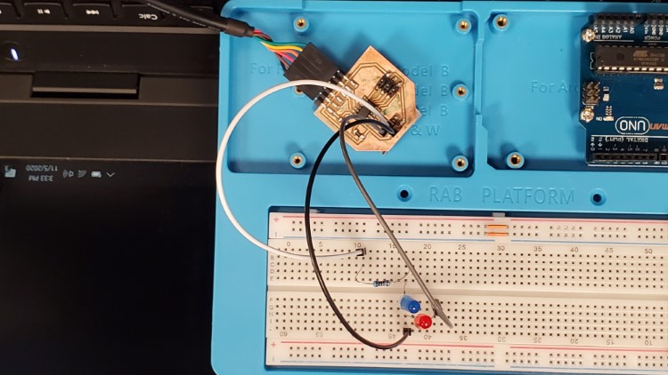
I complied, uploaded the code using the TinyUSB programmer, and tested it
Issues
I kept receiving an error that Tkinter didn’t exist. I did some research and found I had to change the ‘import Tkinter’ to ‘from tkinter import *’. I also had to adjust the python script for the correct com port. That can be found on the Arduino IDE
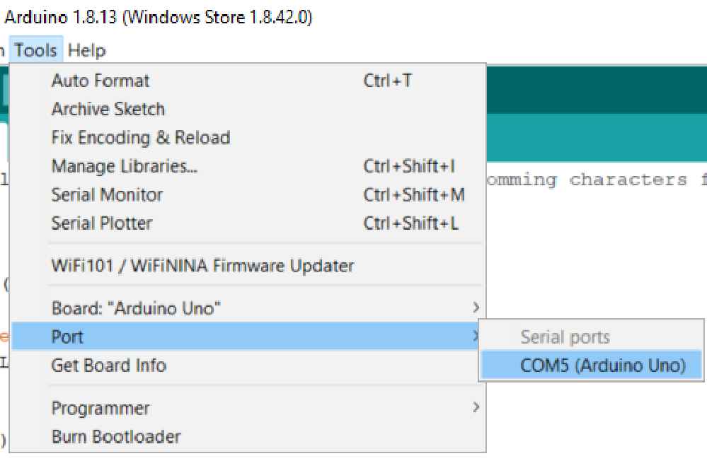
Tools=>Port=>COM5
Files

This work is licensed under a Creative Commons Attribution-NonCommercial-ShareAlike 4.0 International License.