5. Electronics production
Group assignment
The board
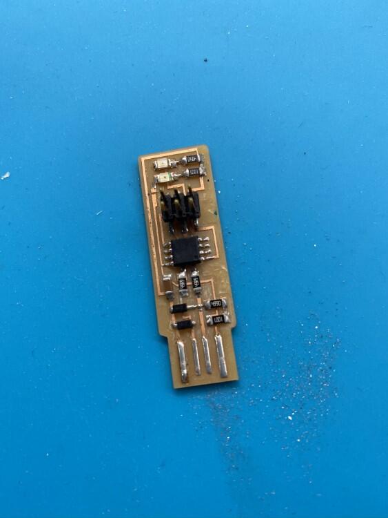
I chose to produce the ATtiny45 tiny ISP from Brian. I liked the design and the integrated USB I/O.
The png files were provided, which made the production much easier.
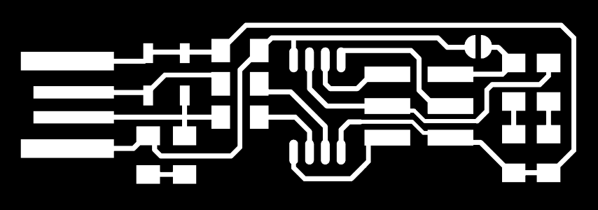
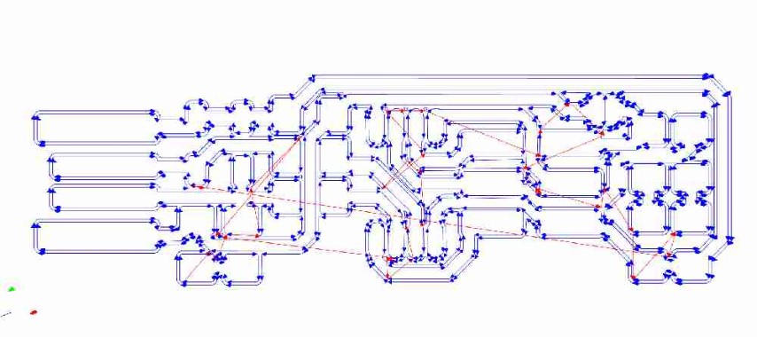
The traces

The outline
CAM production using mods
I chose to product these boards on a ShopBot desktop 2418. It seemed like an interesting challenge as it’s a larger machine and is claimed to be able to cut circuits. We have access to a Modela MX15 milling machine, but the ShopBot is seems to be more popular in labs.
To generate the code for the ShopBot, I used the mods.
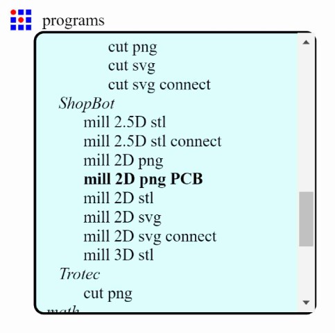
Start by right clicking and selecting “programs”

Next, select “open server program”

From here, there are a number of different options for different machines. Under the ShopBot sub-menu, I chose “mill 2D png PCB”
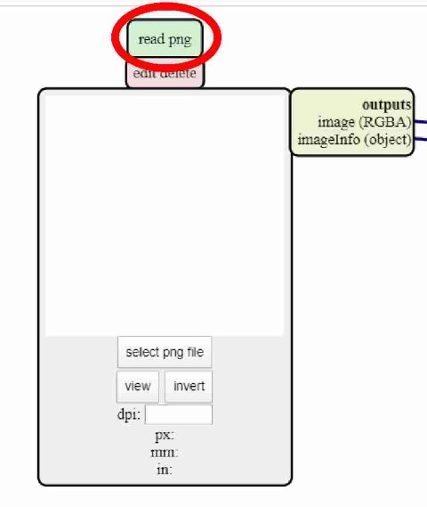
This opens a series of dialog boxes. First, a png needed to be selecting. I did that by selecting ‘select png file’, and navigating to the traces image.
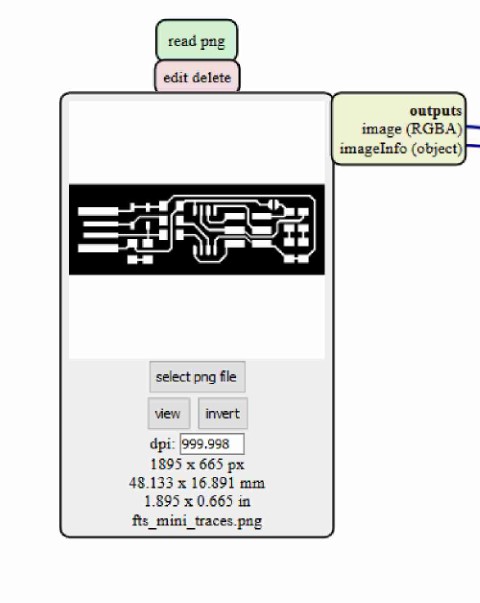
Traces image loaded
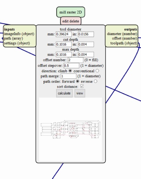
Next, I had to select the tooling and settings. In this step, I’m milling out the traces, so a 1/64” flat end mill was selected. In this window, options such as the tool diameter can be refined, the depth of each cut, the max depth of the process, and the offset number. The offset number is just the number of times the endmill will go around the traces.
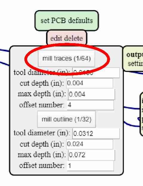
Here is a look at the default settings. These will be used as the control. Note that a small preview window of the milling routine is displayed here as well.
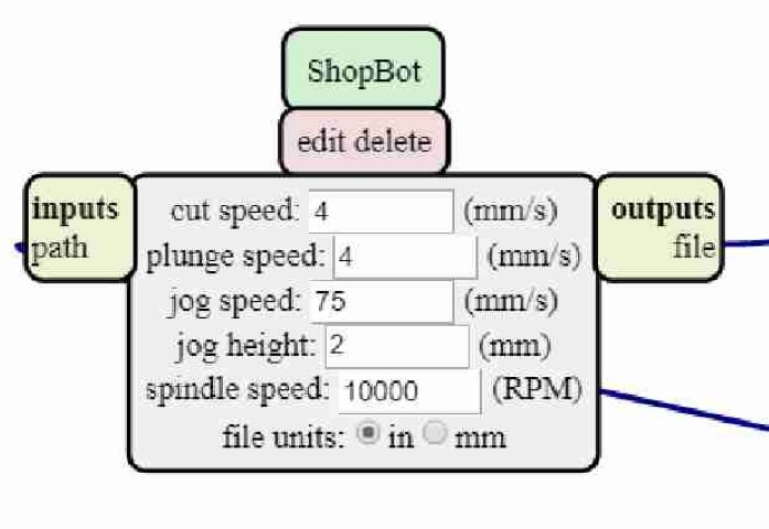
In this window, the settings for the ShopBot can be changed. This is where speeds, feeds, and plunge rate will be entered. I provided a brief description of what these setting mean:
- Cut speed
- How fast the machine moves while cutting
- Plunge speed
- How fast the machine plunges the tool into the material along the z-axis
- Jog speed
- How fast the machine moves when not performing a cutting operation
- Jog height
- Distance above cutting surface the tool lifts when jogging
- Spindle speed
- How fast the tool spins
As I said, I started with the defaults as a control. With those settings correct, select “calculate”
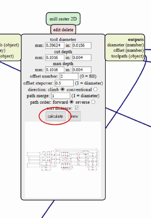
Once this is done, the program will generate the proper code for the machine as well as give a visual representation of the toolpaths. This screen can be used to analyze the toolpath for any problems
Milling using ShopBot
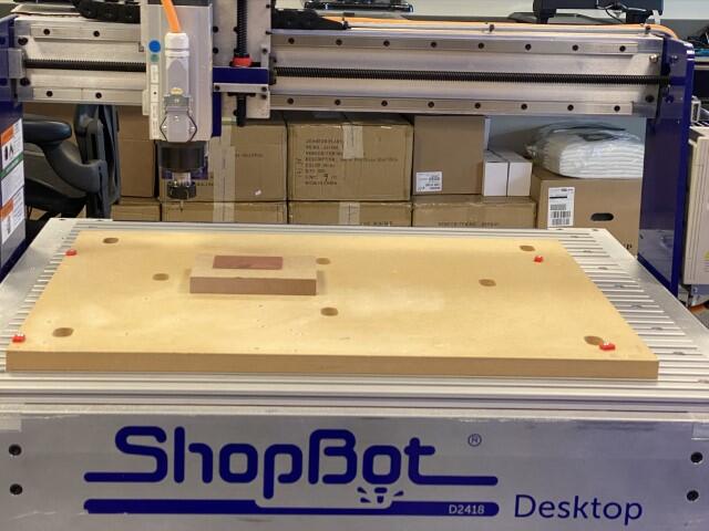
Shopbot Desktop 2418

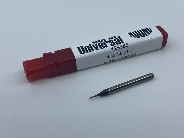
End mill to be used for traces
End mill to be used for cutting out the board
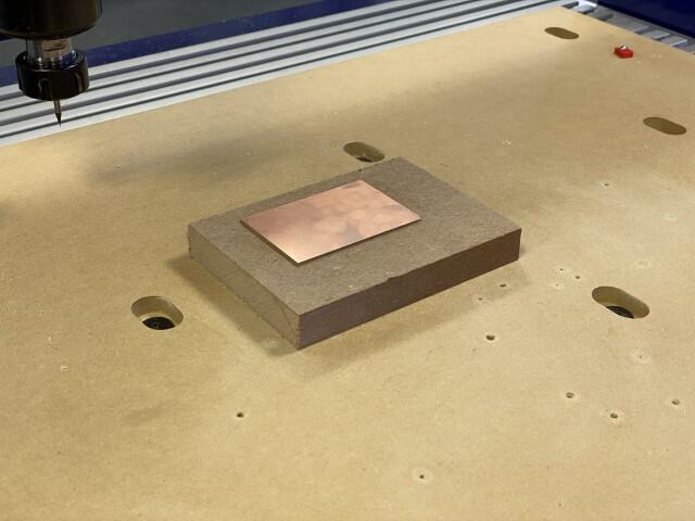
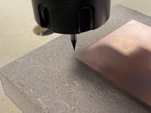
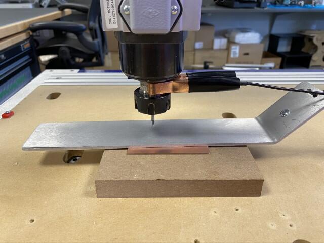
I selected the copper board I planned on using and secured it to the cutting surface with double-sided carpet tape. Note the piece of MDF the copper is affixed to, This is to provide extra height as the end mill wasn’t long enough and the z-axis didn’t have the travel to reach the cutting surface
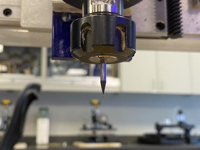
This is the 1/64” end mill inserted into the spindle
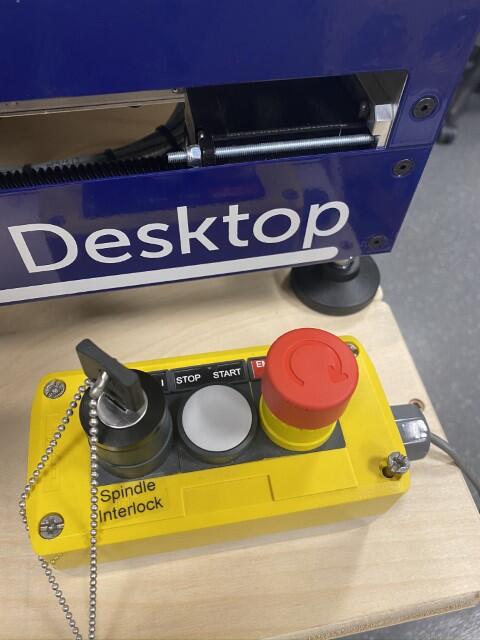
Safety around any equipment is very important. This is the spindle interlock for the ShopBot. The spindle will not operate if the key isn’t inserted and in the “On” position. This is also the emergency stop. If something were to go drastically wrong during operation, press this button
Now that the copper is fixtured and the safety precautions taken, the three axes need to be zeroed out relative to the copper board.
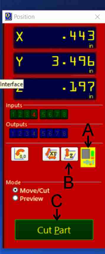
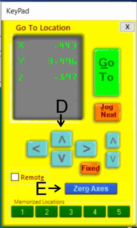
On the red screen, there is a yellow icon (A). Selecting that brings up the movement controls. Within this yellow box, the x and y axes will be moved using the directional arrows (D). Move the machine until the tool is at the lower left of the copper board. Once that position is established, select the Zero Axis button (E), to set the x and y axis to zero
The next step is to zero the z-axis. The ShopBot has the capability to perform this automatically. First, is to place the zero plate under the tool.
Zero place under the tool
Next, back on the red screen, select the z-axis homing button (B). The tool will move to the plate and touch off two times, setting the starting height of the z-axis.
The tests
The first and second tests didn’t go very well. This is what happens when you try to rush. Note that the settings of every test were reset back to default. The changes from default are noted.
Always remember to set the home positions
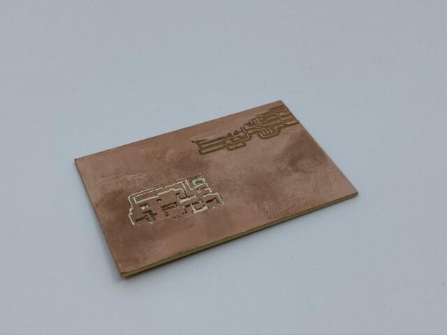
Test 3: Failure. Issues: Broken traces. Copper board loosened during cutting. Jog speed too high.
- Settings: Default
- Cut depth: 0.004”
- Max depth: 0.004”
- Offset number: 2
- Offset stepover: 0.5
- Direction: Climb
- Cut speed: 4mm/s
- Plunge speed: 4mm/s
- Jog speed: 75 mm/s
- Jog height: 2mm
- Spindle speed: 10000RPM
Third test
Test 4: Failure.
Issues: Broken traces. Jog speed still too high.
- Settings:
- Offset: 3
- Cut speed: 3mm/s
- Jog speed: 50mm/s
Test 5: Failure.
Issues: Broken traces.
- Settings:
- Cut speed: 5mm/s
- Jog speed: 10mm/s
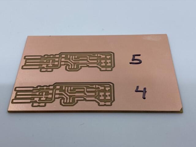
Fourth and fifth tests
Test 6: Failure
Issues: Broken traces
- Settings:
- Increased tool diameter to 0.017” attempting to alter stepover
Test 7: Failure
Issues: Broken traces. Did not cut through copper completely
- Settings:
- Offset: 2
- Cut depth: 0.003”
- Spindle speed: 8000RPM
Test 8: Failure
Issues: Broken traces. Copper peeled up in places. Very rough edges.
- Settings:
- Same as test 7, except direction was changed to conventional
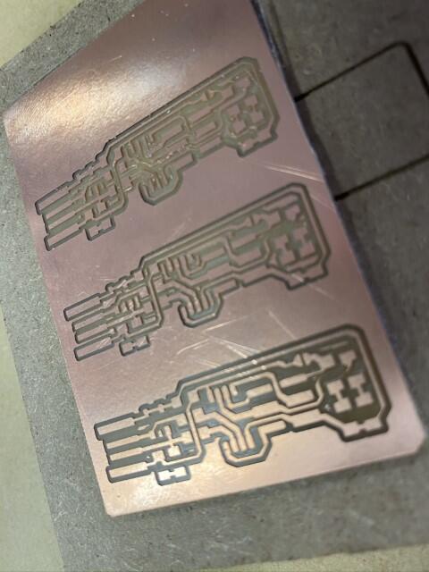
From top to bottom: Tests 6, 7, & 8
Test 9: Failure
Issues: Lost some traces completely
- Settings:
- Offset: 4
- Spindle speed: 14000RPM
Test 10: Failure
Issues: Lost some traces completely
- Settings:
- Offset: 0 (fill)
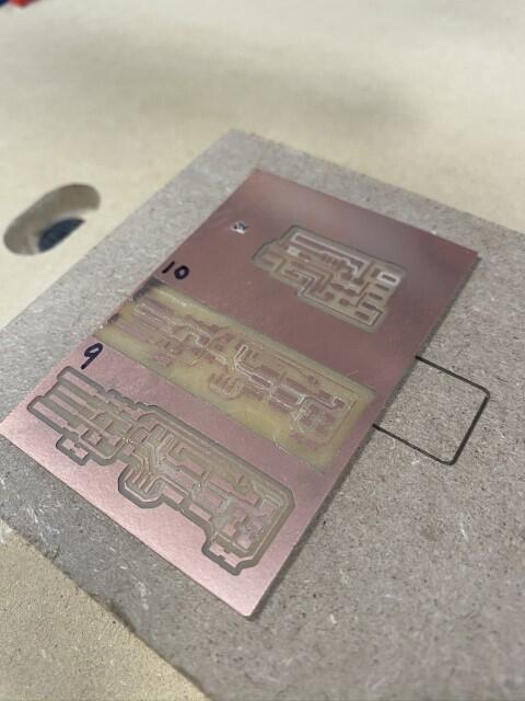
Tests 9 and 10
Test 11: Failure
Issues: Broken traces
- Settings:
- Offset: 3
Test 12: Failure
Issues: Didn’t cut copper in some places
- Settings:
- Max cut depth: 0.002”
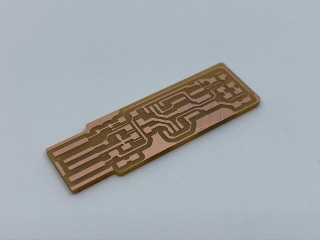
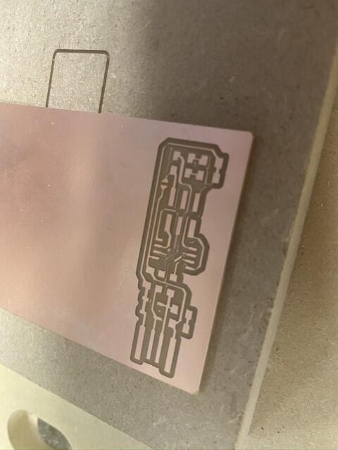
Test 13: Success
Issues: None. I machined the MDF fixture flat and re-zeroed the z-axis.
- Settings:
- Cut depth: 0.002”
- Max cut depth: 0.004
- Cut speed: 3mm/s
- Plunge speed: 2mm/s
- Spindle speed: 8000 RPM
Test 14: Failure
Issues: Attempted same settings as test 13 a few days later. Copper board wasn’t level when secured with tape.
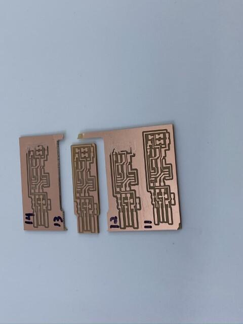
Tests 11-14
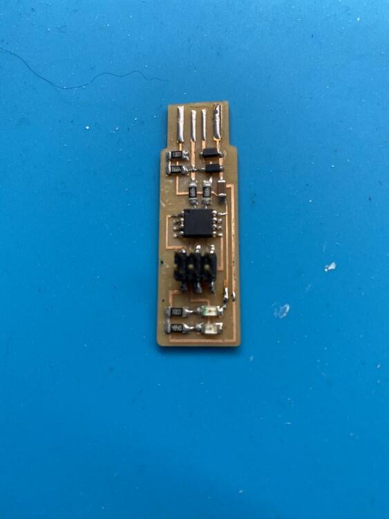
The successful cut
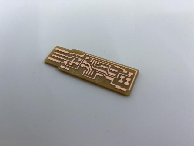
Successful test 13
One last test just to satisfy my curiosity. Same settings as test 13, direction was changed to conventional. The test was a failure as many of the traces were missing or pulled away.
Conventional milling
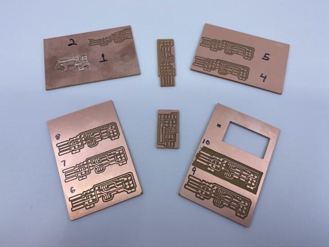
All of the tests and a UDPI adapter board that was cut later
What I learned from this:
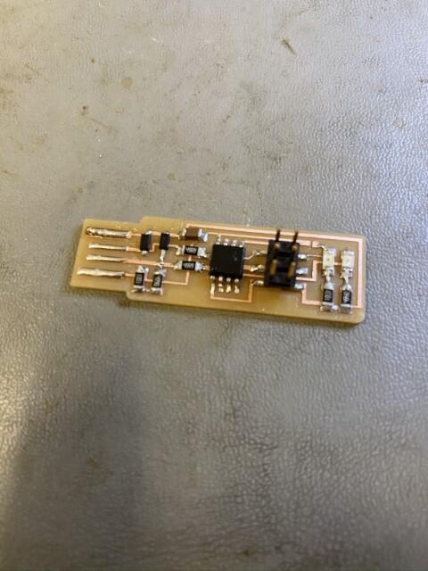
Stuffing the board
With a successful board cut on the ShopBot, the next step was to stuff it with components. To stuff this board, I first gathered the components needed and separated them.
The components used:
-
1 - ATtiny45
-
2 - 1K ohm resistors
- 2 - 49 ohm resistors
- 2 - 499 ohm resistors
- 2 - 3.3v zener diodes
- 1 - red LED
- 1 - green LED
- 1 - 1uF capacitor
- 1 - 2x3 pin header
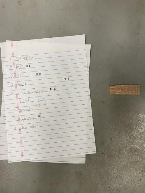
Master class in organization
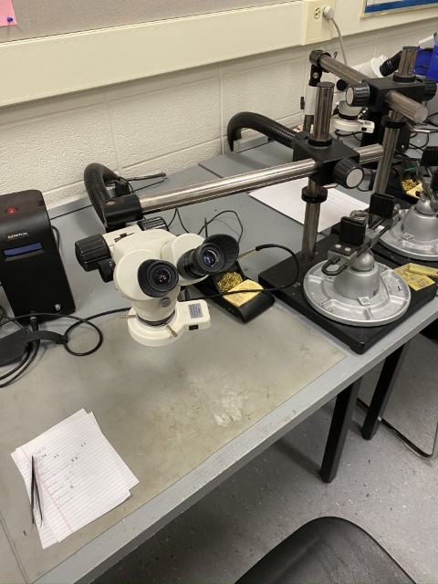
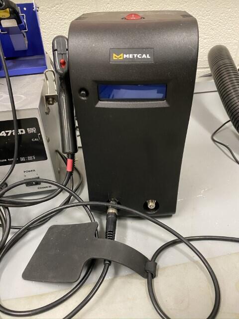
Soldering something this small was made easier with a stereo microscope and a Metcal soldering station
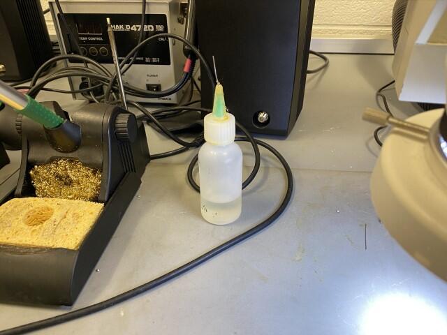
The use of flux is a must with surface mount components. It helps hold the component to the board and also allows the solder to flow easier.
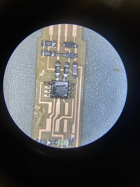
First step is to place the component on the proper pad on the board, usually with tweezers. Next, apply the flux. The flux will help refine the position. While holding down the component with tweezers, press the soldering iron tip between the pad and the component pin. Most components are pre-tinned with solder, so it should bond to the board. After that, move to the opposite pin and pad of the component and repeat the process, only adding solder this time. Once this is completed, go back to the initial pin and add solder to that to complete the joint.
Programming the programmer
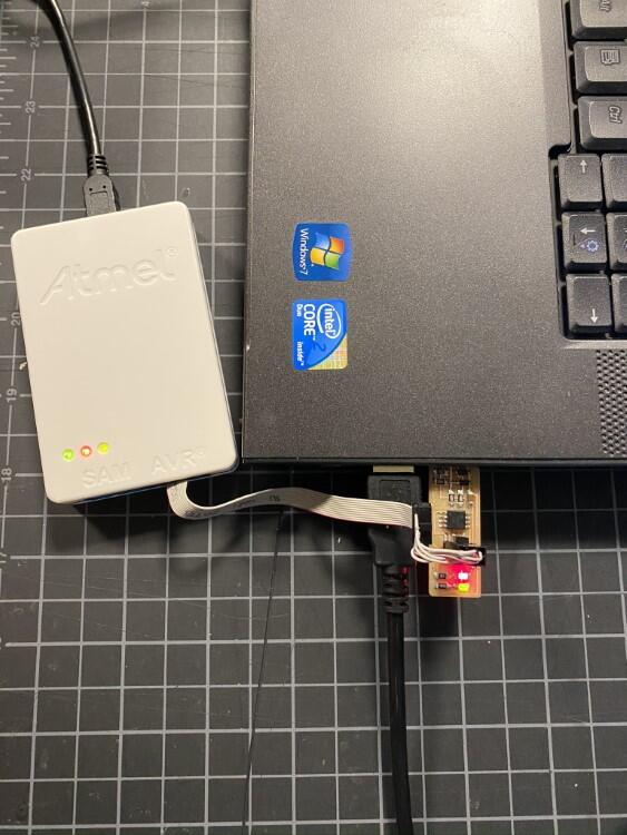
Programming the programmer required the use of another programmer. Here, I chose the Atmel ICE.
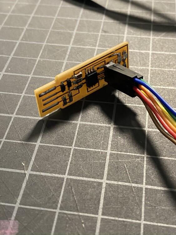
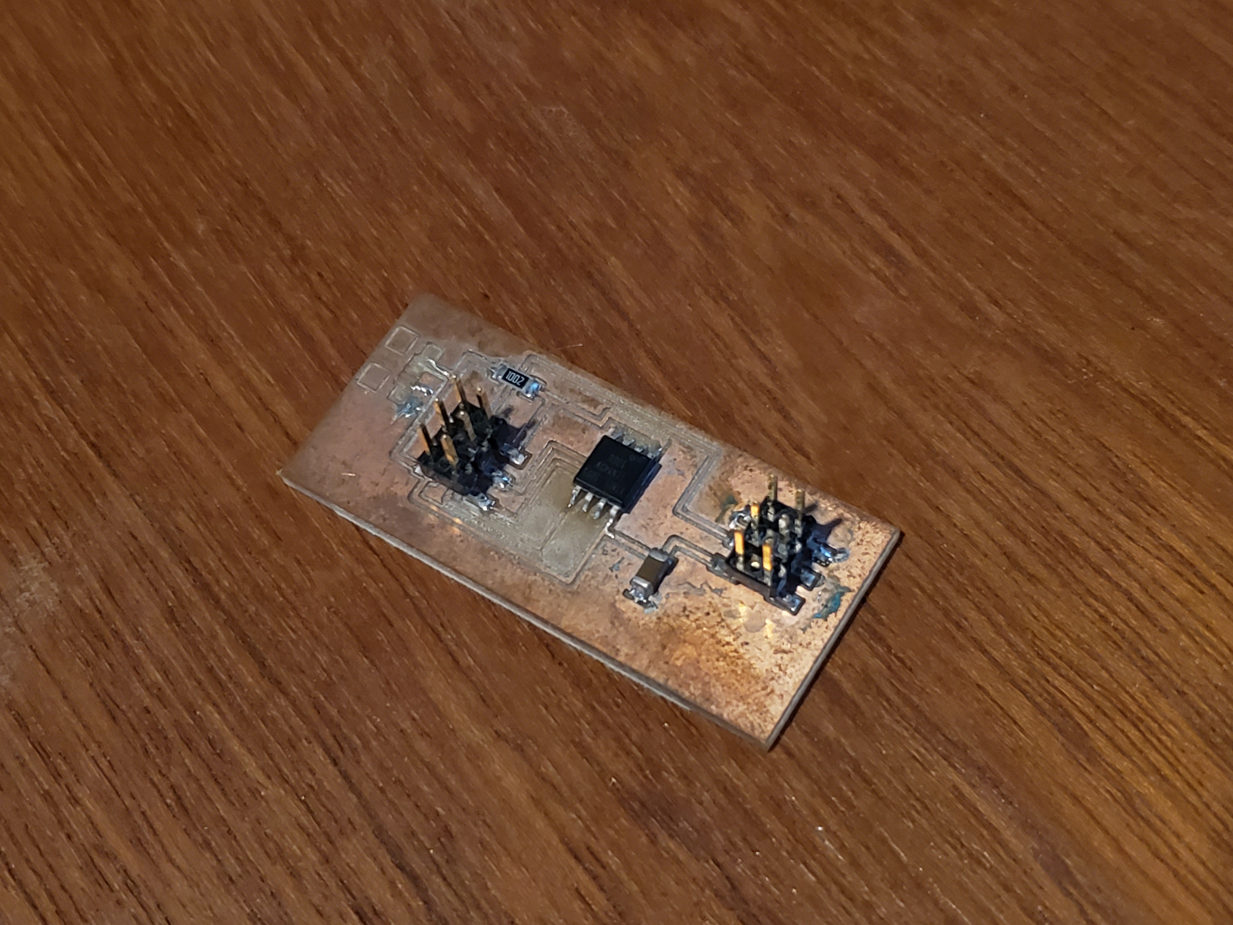
I started with the completed programmer and soldered the jumper closed
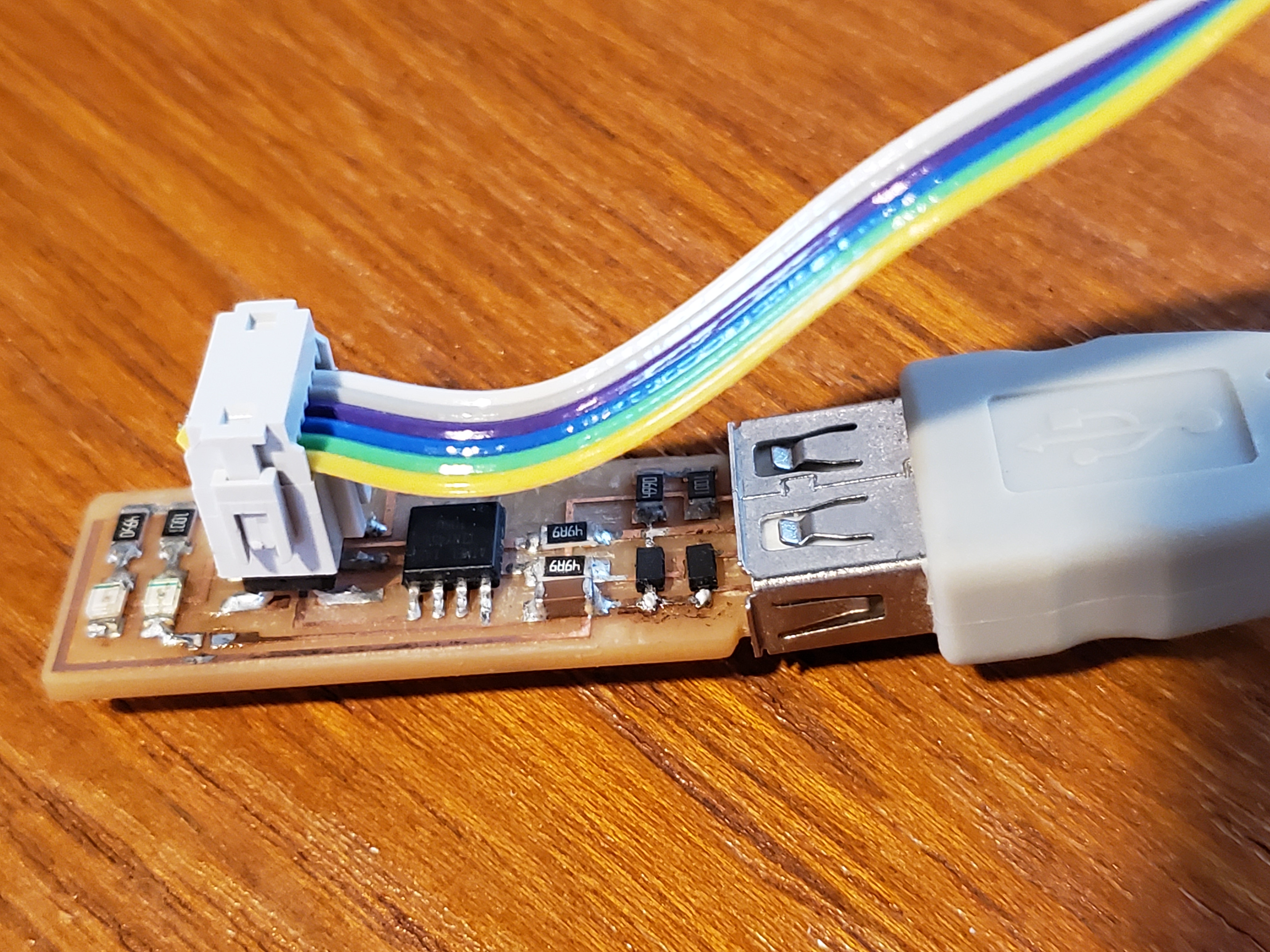
I talked in my instructor, and the Linux OS was suggested over Windows 10 to perform the programming. I started by taking the connecting the wiring from the Atmel to the 6-pin jumper on the programmer.
Then, plugging the programmer into the computers USB slot. A USB extension cable is highly recommended, but I did not have one at the time
With guidance from my instructor, I used the provided make file for reference
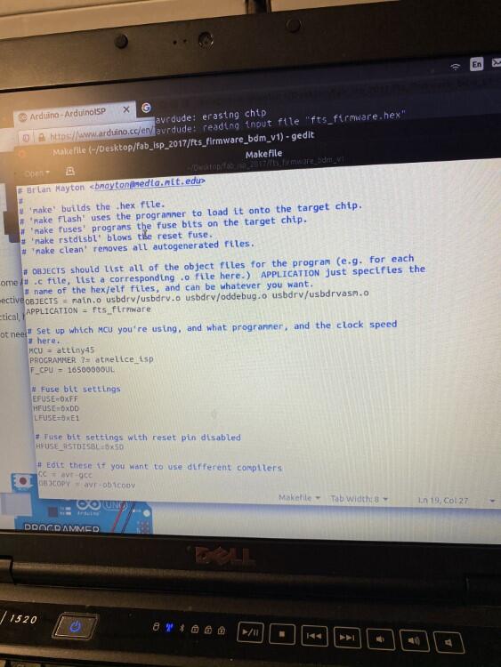
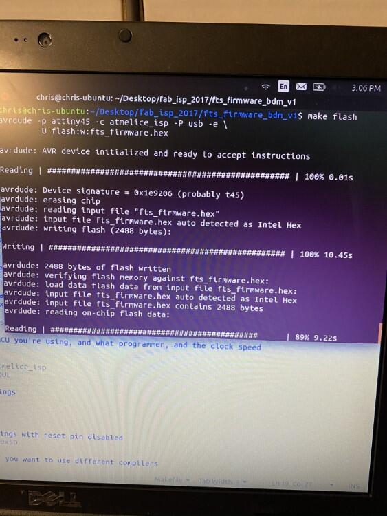
First step was to flash the programmer. In the command line, use:
make flash
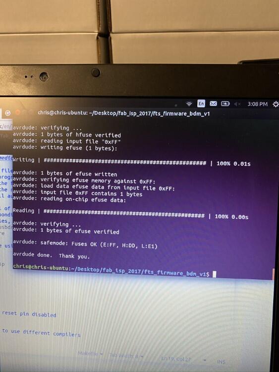
Second step was to program the fuse bits using command
make fuses
Third step was to check to see if the programmer was found. In Linux, connected USB devices can be found by using the command
lsusb
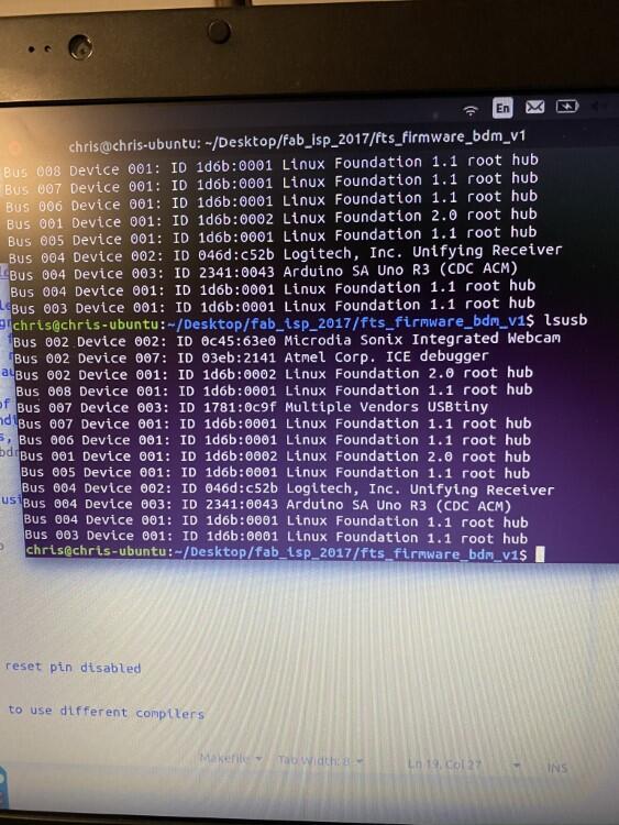
The programmer is ‘Multiple Vendors USBTiny’
Now I know the programmer is recognized by the computer, the next step was to disable the reset. This was done with the command
make rstdisbl
This blows the reset fuse, but also makes it impossible to program the chip again.
The last step before using it as a programmer is to de-solder the jumper
An issue worth noting
As we tried programming this, it would flash, and allow the fuses to be set, but the computer wouldn’t recognize it. We tried different USB ports and different computers, the programmer wasn’t recognized. After some investigating, my instructor found that I had soldered the zener diode in backwards, reversing polarity. Once those were de-soldered and re-soldered correctly, the programmer functioned again.
Testing the programmer
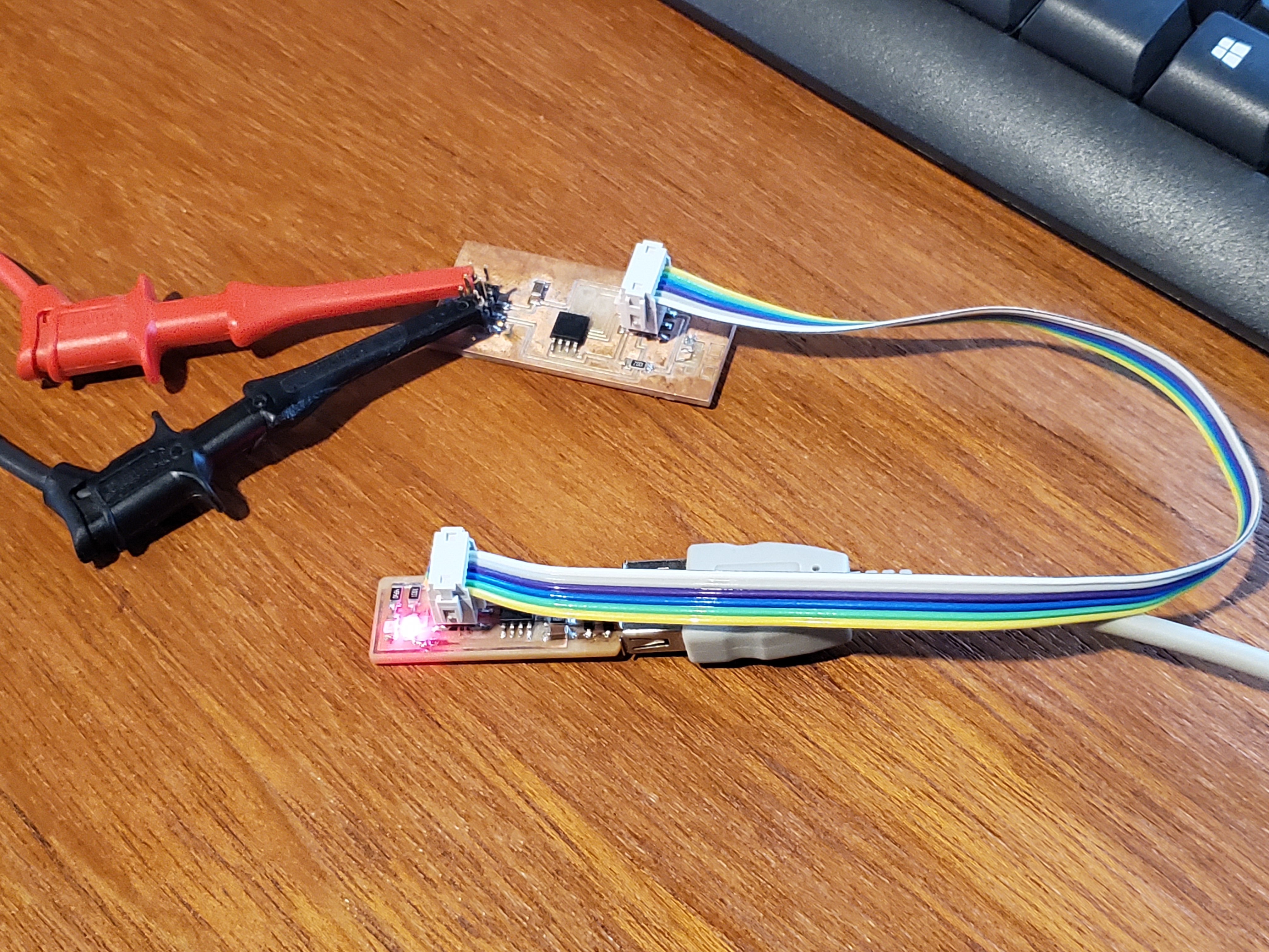
To test the programmer, I needed something to program. I chose a board with an attiny45 that is designed to control addressable LED’s (neopixels)
Using a USB extension cable to plug in the programmer makes for a more reliable connection
The programmer itself doesn’t provide power, so and external power source was used.
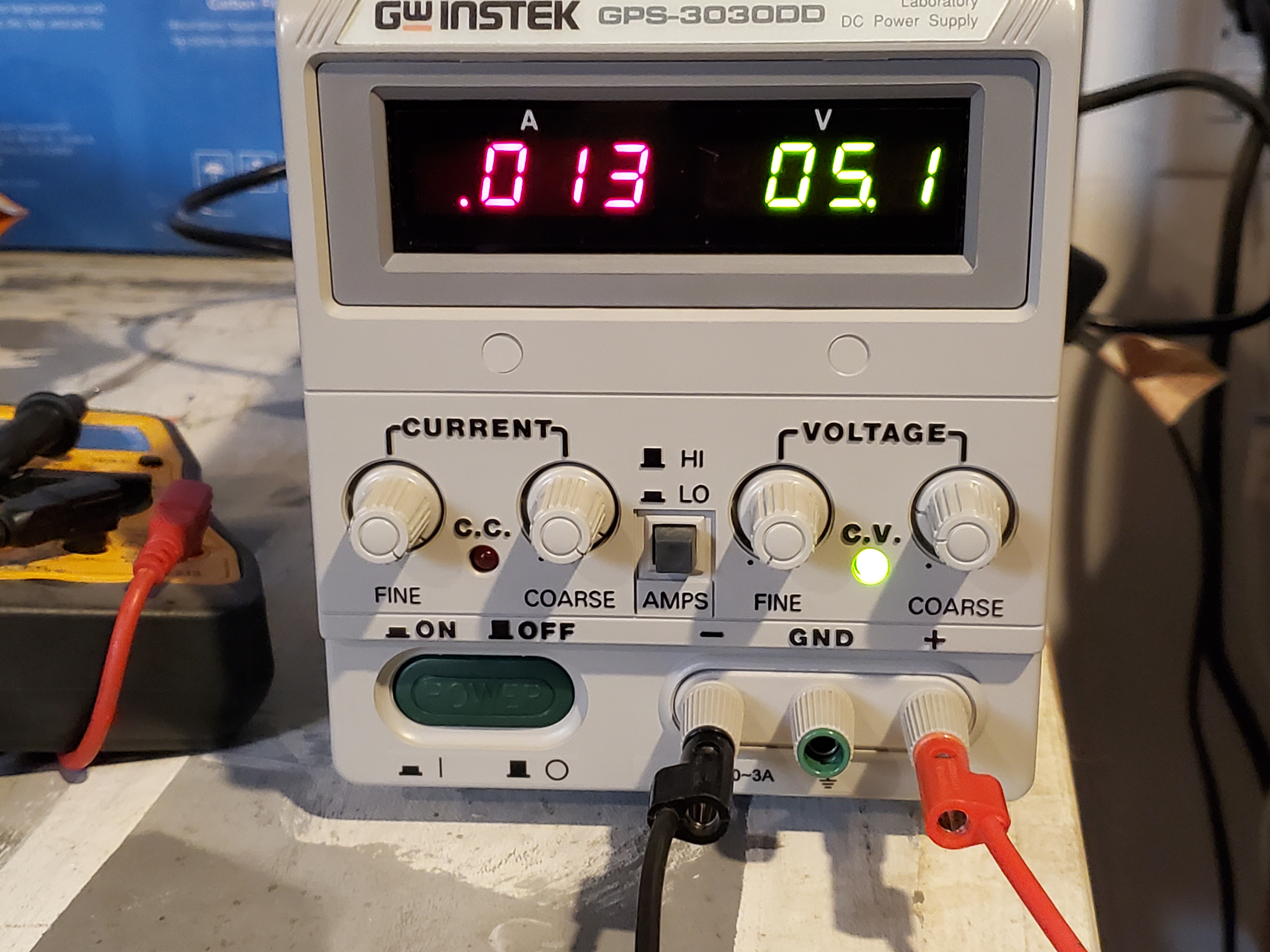
Light is on, and boards are powered up
The Arduino IDE was used to program the board. First, the ATtiny45 boards had to be installed
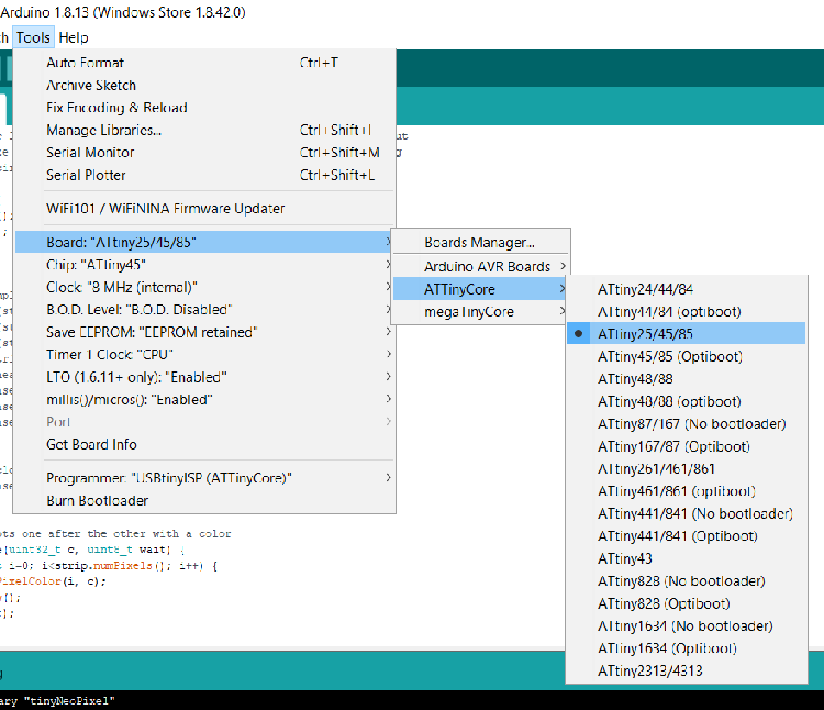
Once installed, open the IDE. To select the attiny45, go Tools > Board > ATtinycore > ATtiny24/45/85
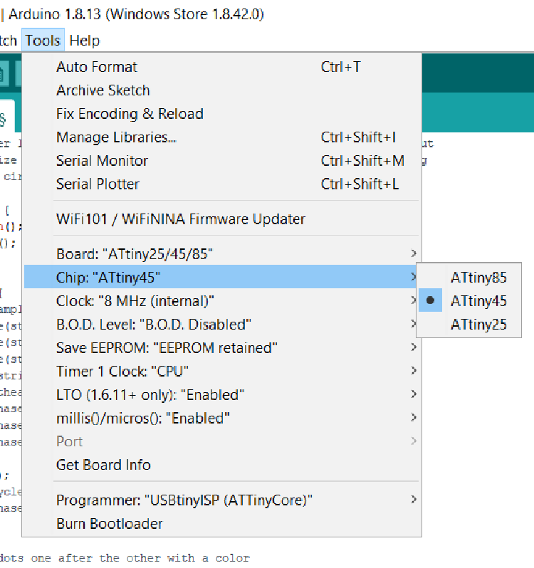
Under the same TOOLS drop-down, change the chip to the ATtiny45
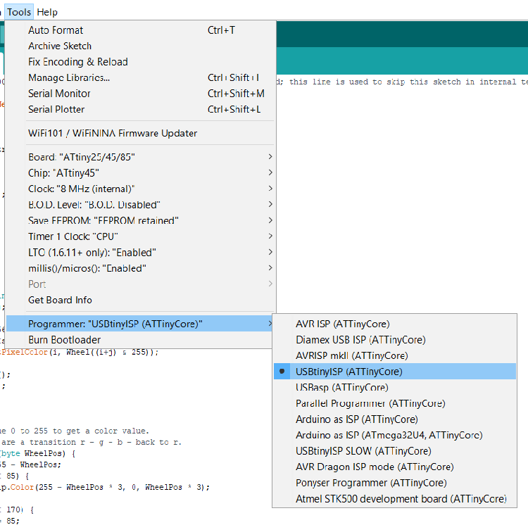
Next, the correct programmer needs to be selected, got to Tools > Programmer
The attinycore download also included libraries designed specifically for the attiny chipsets. To access those, go to File > Examples > tinyNeoPixel > strandtest
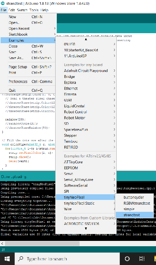
This opens the strandtest sketch. This is what was used to program the board. I didn’t want to just run the strandtest, so I isolated the rainbow animation and created a new sketch from that.
This allowed me to remove a lot of unneeded code, reducing memory requirements.
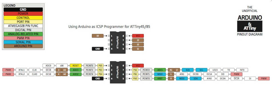
NOTE: The chip on the LED board has pin PB0 setup as the data pin. Looking at a datasheet shows that equates to Arduino pin 0. In the code, the PIN is set to 0.
#if (F_CPU>7370000) //neopixel library required 7.37MHz minimum clock speed; this line is used to skip this sketch in internal testing. It is not needed in your sketches.

#include <tinyNeoPixel.h>

#define PIN 0

tinyNeoPixel strip = tinyNeoPixel(20, PIN, NEO_GRB + NEO_KHZ800);


void setup() {
  strip.begin();
  strip.show(); // Initialize all pixels to 'off'
}

void loop() {
  rainbow(20);
}


void rainbow(uint8_t wait) {
  uint16_t i, j;

  for(j=0; j<256; j++) {
    for(i=0; i<strip.numPixels(); i++) {
      strip.setPixelColor(i, Wheel((i+j) & 255));
    }
    strip.show();
    delay(wait);
  }
}

// Input a value 0 to 255 to get a color value.
// The colours are a transition r - g - b - back to r.
uint32_t Wheel(byte WheelPos) {
  WheelPos = 255 - WheelPos;
  if(WheelPos < 85) {
    return strip.Color(255 - WheelPos * 3, 0, WheelPos * 3);
  }
  if(WheelPos < 170) {
    WheelPos -= 85;
    return strip.Color(0, WheelPos * 3, 255 - WheelPos * 3);
  }
  WheelPos -= 170;
  return strip.Color(WheelPos * 3, 255 - WheelPos * 3, 0);
}
#else //neopixel library required 7.37MHz minimum clock speed; these and following lines are used to skip this sketch in internal testing. It is not needed in your sketches.
#warning "Neopixel control requires F_CPU > 7.37MHz"
void setup() {}
void loop() {}
#endif
Check the sketch by clicking on verify
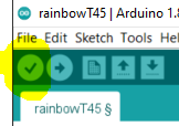
The check mark
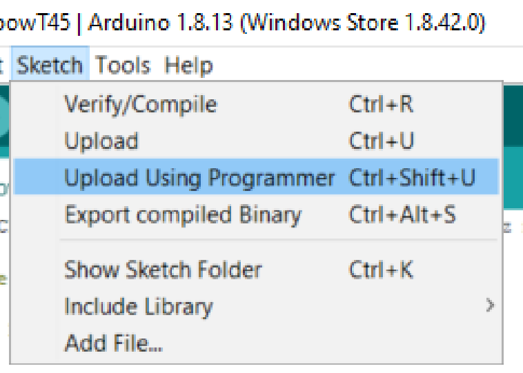
Once it’s verified, upload by selecting Sketch > Upload using programmer
If there are no errors, the program will load
And the program works, as does the programmer
Very nice indeed

This work is licensed under a Creative Commons Attribution-NonCommercial-ShareAlike 4.0 International License.