3D Scanning and Printing
This week I learned about 3D scanning and printing. This included:
Unit Description
Group assignment:
- Test the design rules for your 3D printer(s)
- Document your work on the group work page and reflect on your individual page what you learned about characteristics of your printer(s)
Individual assignment:
- Design and 3D print an object (small, few cm3, limited by printer time) that could not be easily made subtractively
- 3D scan an object (and optionally print it)
Learning outcomes
- Identify the advantages and limitations of 3D printing
- Apply design methods and production processes to show your understanding of 3D printing.
- Demonstrate how scanning technology can be used to digitize object(s)
Checklist
Linked to the group assignment page
-
Linked to the group assignment page:
-
There are two types of assignments, one group and one individual, since I am alone in my personal Fab Lab I will do both. All of my work will be documented here, so there won’t be a group assignment page.
-
Test the design rules for your 3D printer(s)
-
Document what you learned about characteristics of your printer(s)
My personal Fab Lab is equipped with an Original Prusa i3 MK3S+ 3D printer. All of my filament is PLA of various colors; including clear.
You can learn more about about the vendor Prusa Research and the machine I have here.
Technical Parameters
| Build Volume | 25×21×21 cm (9.84"×8.3"×8.3") |
| Layer height | 0.05 - 0.35 mm |
| Nozzle | 0.4mm default, wide range of other diameters/nozzles supported |
| Filament diameter | 1.75 mm |
| Supported materials | Wide range of thermoplastics, including PLA, PETG, ASA, ABS, PC (Polycarbonate), CPE, PVA/BVOH, PVB, HIPS, PP (Polypropylene), Flex, nGen, Nylon, Carbon filled, Woodfill and other filled materials. |
| Max travel speed | 200+ mm/s |
| Max nozzle temperature | 300 °C / 572 °F |
| Max heatbed temperature | 120 °C / 248 °F |
| Extruder | Direct Drive, Bondtech gears, E3D V6 hotend |
| Print surface | Removable magnetic steel sheets(*) with different surface finishes, heatbed with cold corners compensation |
| Printer dimensions (without spool) | 7 kg, 500×550×400 mm; 19.6×21.6×15.7 in (X×Y×Z) |
| Power consumption | PLA settings: 80W / ABS settings: 120W |
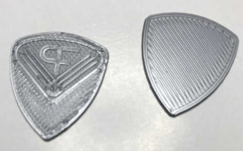
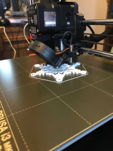
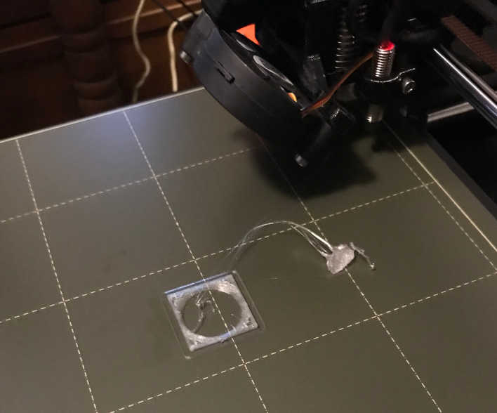
A new firmware version was available at the beginning of this cycle, so I downloaded and updated the firmware. Everything seemed to work, but I did not do an exhaustive test. When I tried my first test part, a snowflake, it would not stick to the table. Further investigation found that I needed to perform a First Layer Calibration; I did this multiple times and ended up lowering the Z axis by 1.255mm. That was the sweet spot for moving forward. Rather that trying the snowflake each time, I have a little guitar pick that is a much quicker test. I had multiple fails before and after the First Layer Calibration. These are the last two that proved I had it calibrated properly.
Now I have a nice white snowflake for a decoration :)
Now I can confidently test the design rules for my 3D printer!
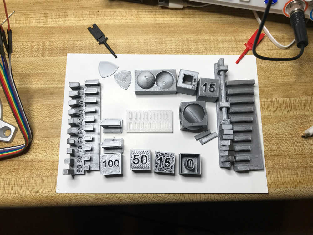
To test the design rules for my 3D printer, I will take it through the course set by Neil in the class content. You can find the files I use in the Fab Academy 3D Scanning and Printing under Design Rules, but I will include them at the bottom of the page as well in a compressed folder. The compressed folder also has the PrusaSlicer and Gcode used to print the tests.
I unloaded the white MiKA3D Normal PLA 1.75mm Filament and loaded the gray 1.75mm filament provided by Prusa Research loaded, to use for testing.
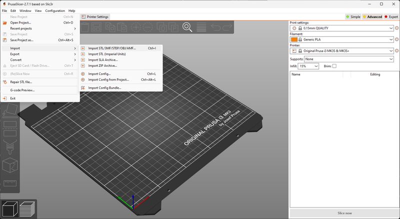
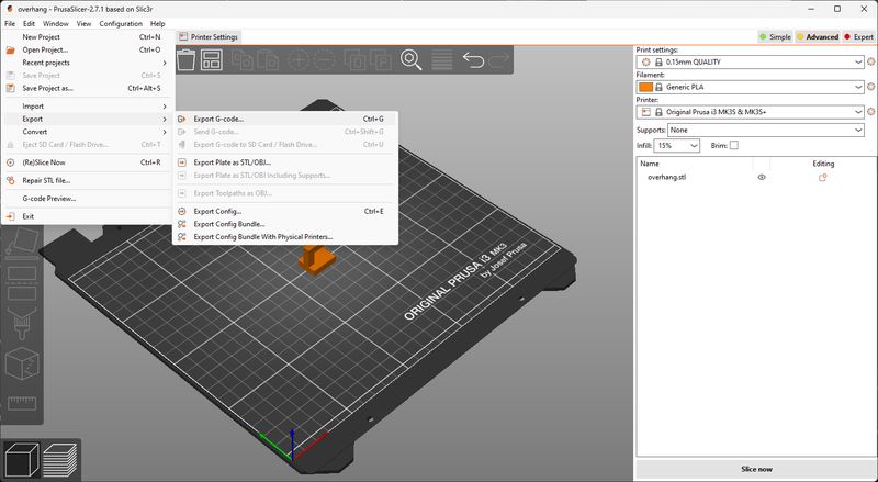
Using my new knowledge obtained from setup learning I described above, my workflow will be to download the test file, import into PrusaSlicer, save as a Project, then Export as a gcode file. Then I tranfer the gcode file to the MicroSD card and plug that into the Prusa i3 MK3S+ 3D printer. Select the file from the MicroSD card and push the button to print. The printer heats up, performs a level test, lays out a test bead and then begins working.
Here are the screenshots of that workflow:
Import:
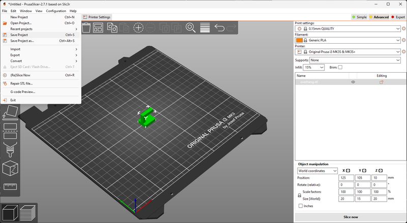
Save Project:
Export GCode:
- Supports
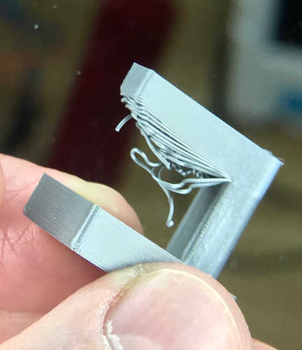
Overhang - downloaded the stl file and printed it without modification. It’s about a 20 minute print on my printer. Learning moment…Don’t forget to add the supports when you are expected to :) For your viewing pleasure, I will include the shot without support; you’ll understand why. By the way, it only took an extra 7 minutes. I put supports everywhere just to be safe.
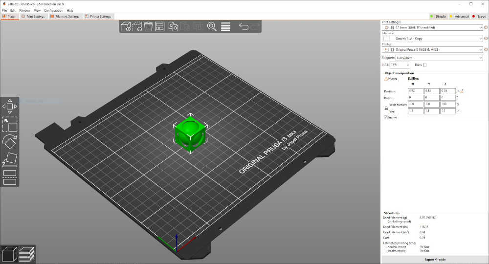
In the below screenshot, in the upper right corner, you can see my Print settings (0.15mm thickness of layer), Generic PLA, Printer I am using, and I used the default 15% Infill, but you can see in the screenshot where I change Supports from None to Everywhere:
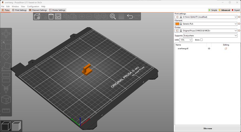
As a note: You can change the thickness of the layer in Print settings to achieve higher or lower detail, but I used the default setting of 0.15mm. I would imagine the thinner layers would take more time. I will have to test that to see the results in a future spiral :)
Overhang…Take 2 :) The 7 minutes were worth it:
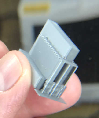
Removing the supports was very easy! I did most by hand/fingers and cleaned up the rest with a razor. Easy peasy!
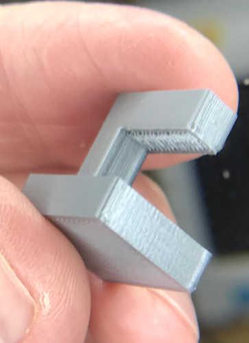
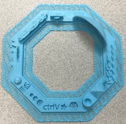
Clearance - downloaded the stl file, made sure the supports were everywhere and printed. I don’t have a lot of experience with 3D printing and this part has always puzzled me. How can you print a part that has moving parts?! I look forward to watching this :)
The clearance design rules test is over 2.5 hours, so we have time to design, talk, relax… I have to tell you, “right now, I am in a happy place!” This is what I have been hoping for; though I didn’t know exactly what it looked like. This is it and there’s so much more!” I need to enjoy this moment, for there are hard times ahead :)
I think we’re makin’ somethin’ :) Love this! It’s what we’re made for! Can you feel it?! You should see it now… Rockin’ Roll!
This is the result of the clearance test with supports.
![]()
The post processing on this part was more tedious and required needle-nosed pliers and a needle. It was enjoyable and rewarding to watch the part emerge. Thank you for making this and other test parts available Neil! This was really amazing to me and such a great learning experience. I could not get the last square nut free without breaking the rod; the clearance was so small that the PLA fused around the rod.
![]()
- Unsupported
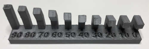
Angle - downloaded the stl file, imported it into PrusaSlicer, then exported it as .gcode and printed it without modification. The print took 1 hour and 8 minutes. Signs of the need for supports started at 40 degress and got progressively worse.
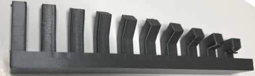
Overhang - downloaded the stl file, imported it into PrusaSlicer, then exported it as .gcode and printed it without modification. The print took 1 hour and 42 minutes. Signs of the need for supports existed throughout and got progressively worse as the overhang lengthened.
Bridging - downloaded the stl file, imported it into PrusaSlicer, then exported it as .gcode and printed it without modification. The print took 1 hour and 52 minutes. I am amazed at the outcome of the print. Other than the spider webs, the print was flawless.
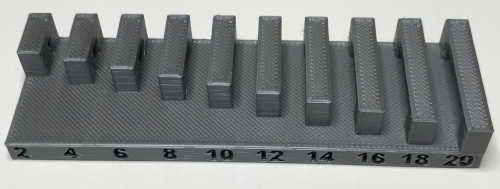
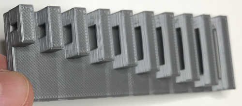
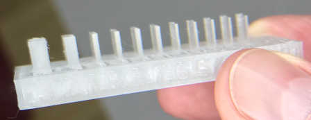
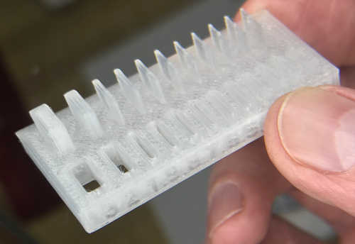
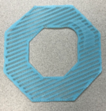
- Wall Thickness - downloaded the stl file, imported it into PrusaSlicer, then exported it as .gcode and printed it without modification. The print took 50 minutes. I did this design rule test print last. I wanted to use the clear filament to try and match the print Neil did; Neil’s print wins :)
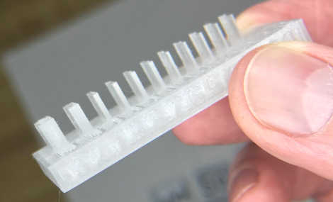
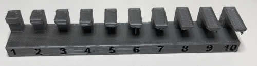
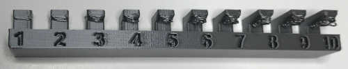
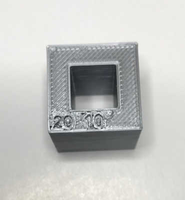
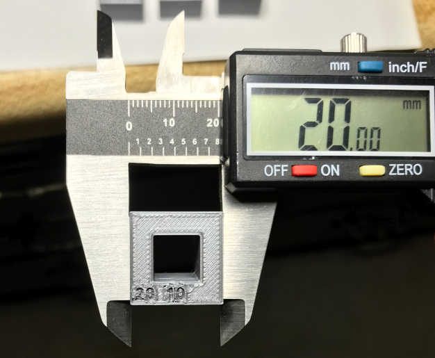
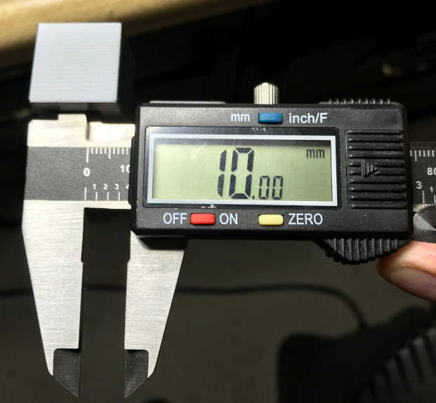
- Dimensions - downloaded the stl file, imported it into PrusaSlicer, then exported it as .gcode and printed it without modification. The print took 40 minutes. I measured with a digital caliper and the dimensions were right on! 20.00mm and 10.00mm
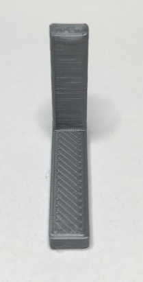
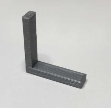
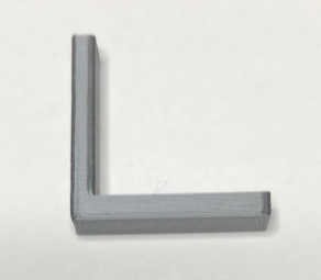
- Anisotropy - downloaded the stl file, imported it into PrusaSlicer, then exported it as .gcode and printed it without modification. The print took 10 minutes. The lines of the print are visible; show the layers of the print. It is amazing how strong the joint of the angle is.
- Surface Finish - downloaded the stl file, imported it into PrusaSlicer, then exported it as .gcode and printed it without modification. The print took 1 hour and 3 minutes. Although the finish in not pristine, I still love seeing a spherical shape printed :) Maybe a little glasscoat and it will be perfect!
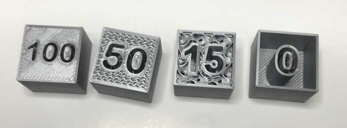
- Infill - downloaded the stl file, imported it into PrusaSlicer, then exported it as .gcode and printed it without modification. The print took 46 minutes. The funny thing about this print…I let it finish, so the infill was not visible :)
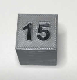
I printed again and stopped the print when it was 75% finished. After printing the 15% infill, I modified the FreeCAD file provided by Neil; this required changing the number as well as the font file, then exporting as the stl file. Then I imported the files into PrusaSlicer, change the infill percentage accordingly, then exported it as .gcode and printed it. The zeroes were tricky :) Arrghhhhh!!
Explained what you learned from testing the 3D printers
-
Explained what you learned from testing the 3D printers:
-
I learned the workflow of bringing a 3D model into PrusaSlicer by using import STL, saving it as a project .3MF and exporting it as .gcode for use in the 3D printer.
-
There are so many variables you have to be aware of. As a ‘lonely’ student, searching the Internet is priceless. No wonder the The Fab Academy Handbook 2021 states that “it is (nearly) impossible for a student to complete the course on their own”. It goes on to say, “and workgroup ensures that one student’s strong suit may help make up for another student’s weak spots and vice versa.” The Internet fills in for the workgroup I am missing. Global Open Time is the community filling the gap. Thank you!!
-
Once you get the 3D printer calibrated properly and keep the nozzle clean, it rarely has problems.
-
Post-processing is a tedious part of 3D printing. I don’t think people realize the time required to design, print, and post-process 3D printed parts. However the time waiting for the printer to complete a print is time that can be used toward time management…parallel development!
-
So far the coolest thing I have learned is the ability to print moveable parts by designing clearances into the part. Adding supports makes this possible.
Documented how you designed and 3D printed your object and explained why it could not be easily made subtractively
- Documented how you designed and 3D printed your object and explained why it could not be easily made subtractively:
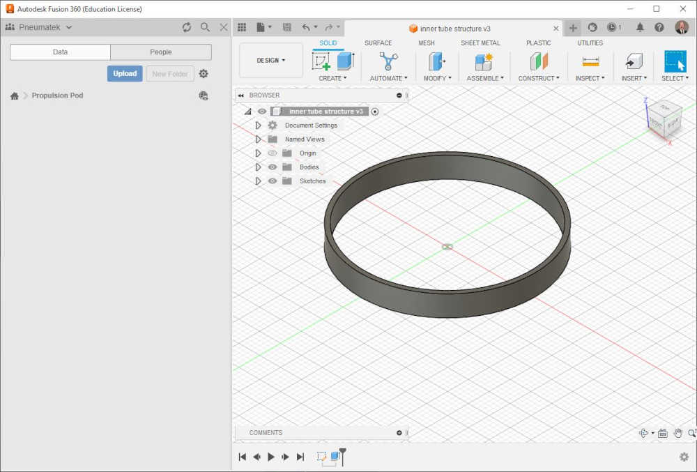
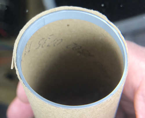
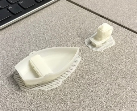
While I was waiting for the design rules print job, I thought I would catch up on documentation. After I printed the snowflake, my mind cleared and I began using the printer as it was designed. I needed support ribs inside my propulsion tube. Measuring the inside diameter was tricky; the material is only .25mm thick, so it flexes when I measure with the digital caliper. I measured 42.25mm, so I went with that. I designed a cylinder in Fusion 360 and gave it an offset of 1mm.
I saved it as an .stl file and imported it into PrusaSlicer, then exported it as .gcode. I saved it on the SD card, plugged it into the Prusa, and printed it; that simple! My first print was too big for the tube, so I reduced the diameter and printed again. Still not a good fit, so I reduced it again. Third time was a charm! As it turns out, the the pontoon tubes are slightly larger that the propulsion pod tubes, so the second print was pretty close to what I need; I’ll tweak it a little and call it good.
Designing has been my biggest challenge in Fab Academy, but I continue to improve with each assignment. I leaned heavily on Sketchup up to this point, but I am using Fusion 360 for the 3D printing design. To learn, I started with this simple part. I knew what I wanted, so I made measurements and jumped in to designing. This was very rewarding for me, but I know I have a long way to go. I will cover the workflow here:
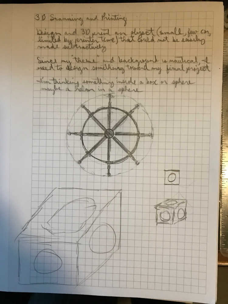
- Come up with an idea, sketch pictures, take measurements, and then design in software. My initial idea was in the nautical direction. See my notes and sketch below:
-
During Global Open Time (GOT), Adrian showed us the Sphere in a Box he designed and printed during Fab Academy; I was real happy to see that my idea was doable. Then Rico demonstrated the ease of modeling in TinkerCAD by making a ‘Tesseract Cat’ right before our eyes; he finished in under 3 minutes!!! I did play around with TinkerCAD after GOT, but I had some gaps in my knowledge and had to go back to Fusion 360. I found an Instructable called “Impossible Object With Fusion 360 - Box and Ball” provided by CmdrZin I gave it a whirl, but got frustrated after several attempts. I decided to finish all of the Design Rules, experiment with Lego MindStorms RCX Brick, and call it a day.
-
After a night of rest and strange dreams, I had some time of devotion and meditation, and a Sunday dinner. Time to get back into it! I decided to give the “impossible object” another go. So here we go:
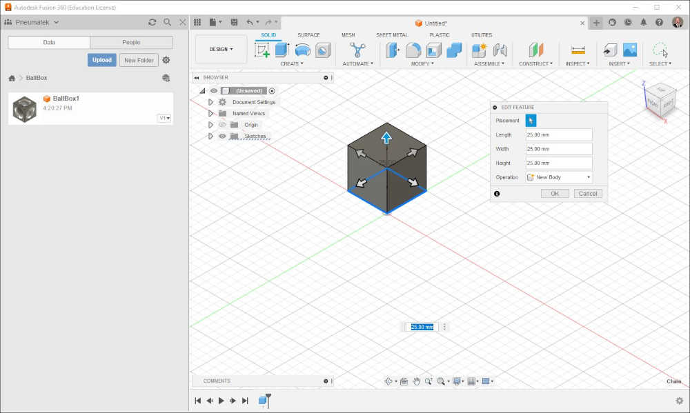
Use Create > Box to make a 25mm Cube sitting on the XY plane with a corner at the origin (0,0,0).
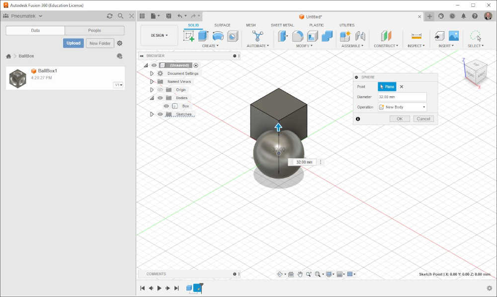
Use Create > Sphere (New Body) to make a 32mm diameter sphere at the origin, selecting the XY plane for it, as a New Body.
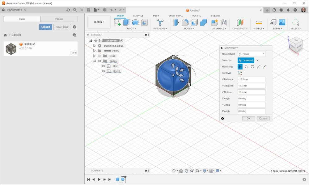
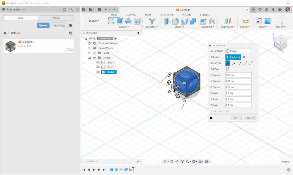
Select Body 2 (the Sphere) and move it X: -12.50mm, Y: 12.50mm, Z: 12.50mm to place it in the center of the Cube.
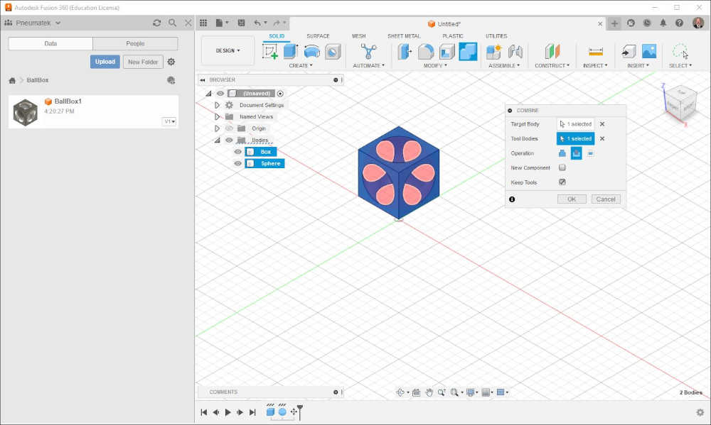
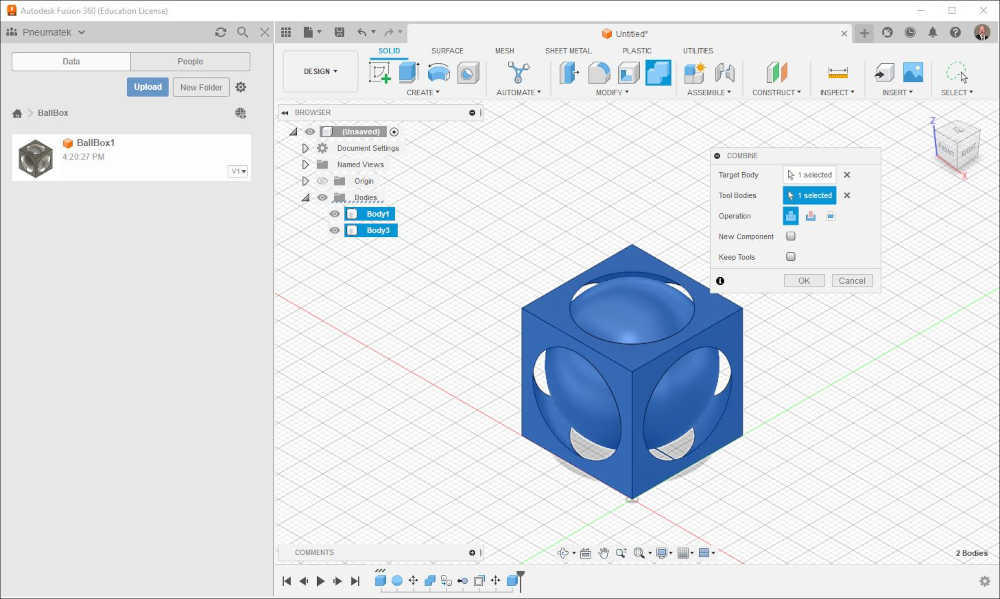
Use Modify > Combine and select the Box (Body 1) as the Target. Select the Sphere (Body 2) as the Tool. Select Cut as the Operation. Select Keep Tools also. This will save some steps later. Select OK to cut the Box.
Right-Mouse Click (RMC) Body 2 and select Copy (Not Move/Copy). Then RMC in an open area and select Paste. Select OK since the body is positioned is the center of the Cube the same as Body 2.
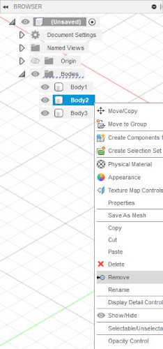
RMC Body 2 and select Remove.
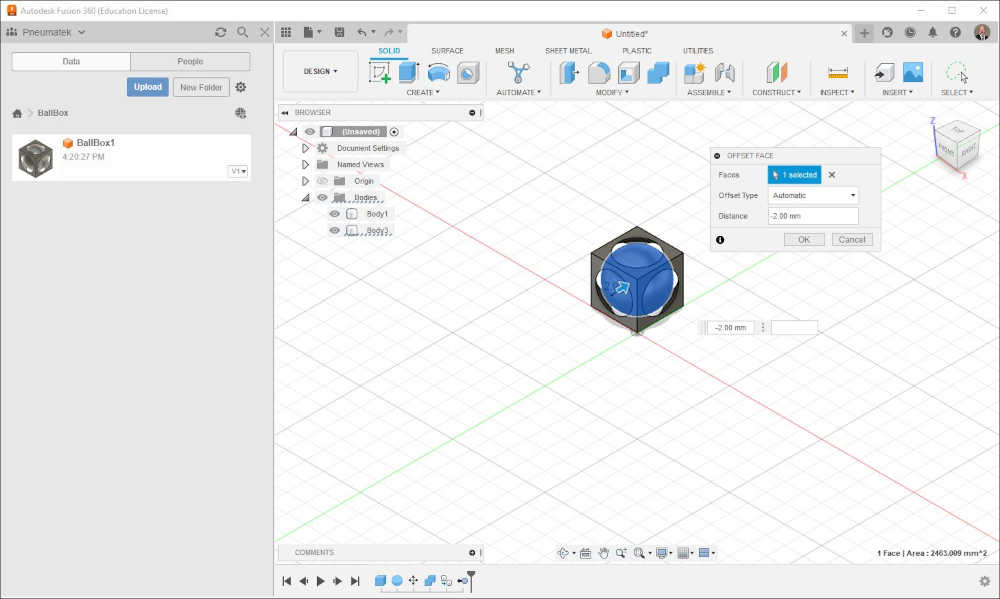
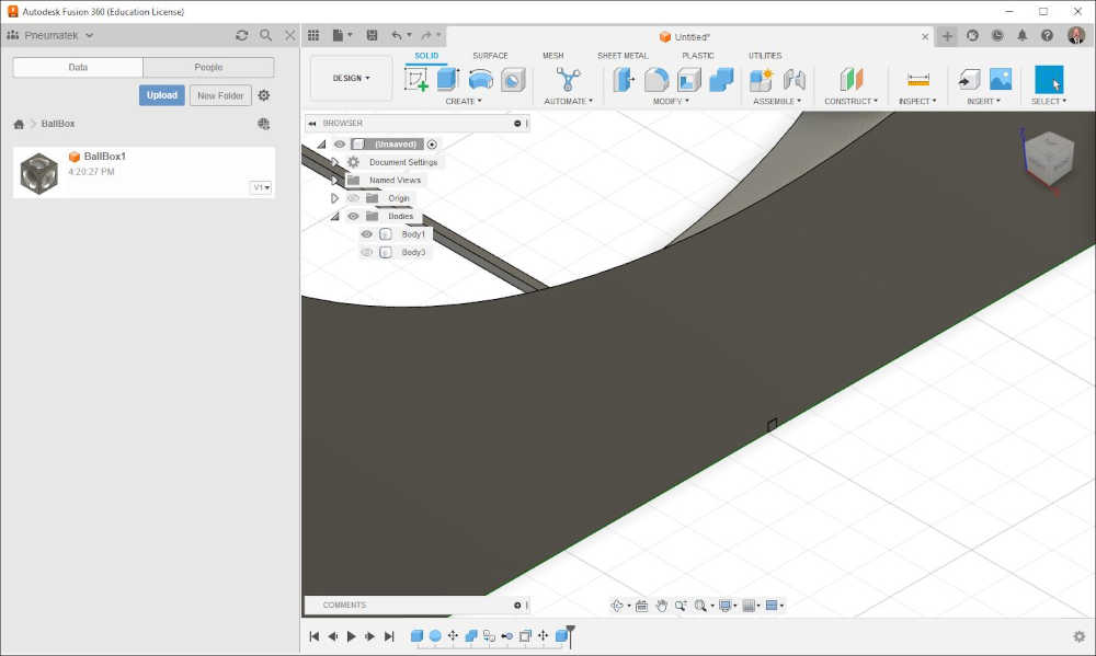
Use Modify > Press Pull to resize Body 3 to 28mm diameter. (reduce by 2.00mm radius)
This next step is used to trick the slicing software into thinking that the Box and Sphere are one object.
We do this by adding a 0.1mm x 0.1mm x 12.5mm bar where the objects will be flat on the printer’s base plate. But first, we need to raise the sphere up 1.5mm so that its contact point is the same as the base of the Box.
RMC Body 3 and use Move/Copy to raise it up 1.5mm in the Z direction.

Next, hide Body 3 by clicking OFF its (show all) eye.
Use Create > Box and select the XY plane and Select Top view on the view gizmo. This will allow us to use a center snap that will appear in the middle of the right edge of the Box. If center snap doesn’t work close to the 12.5mm mark is close enough (zoom in if you need to :) Set you initial dimensions to 0.1mm for both measurements, then click Home in the Gizmo and click near the bottom center of the box (Body 1). Adjust your placement parameters to Length: 12.5mm, Width: 0.1mm, Height: 0.1mm Trust me…I’ve been down this road before :) Make sure the “connecting bar” is at the same bottom level as the box (Body 1)
With this as the first corner, draw a 12.5mm x 0.1mm base that extends to the middle of the base of the Box and the give a 0.1mm height. Use the Join Operation to have it connected to the Box. This is called a “connecting bar” and makes it all one part.
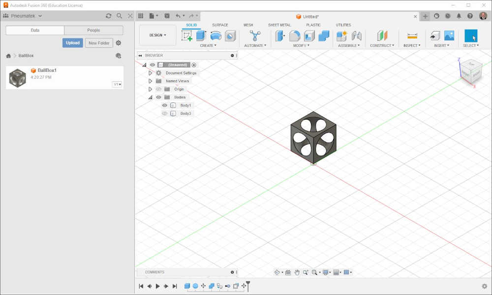
Unhide the Sphere (Body 3) and use Modify > Combine with Body 1 as the Target and Body 3 as the Tool. Unselect Keep Tools if it is still selected. Use the Join Operation. Select OK.
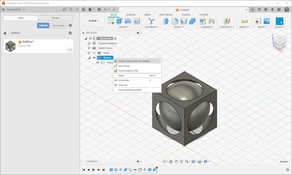
RMC Bodies and select Create Components from Bodies to generate Component1:1.
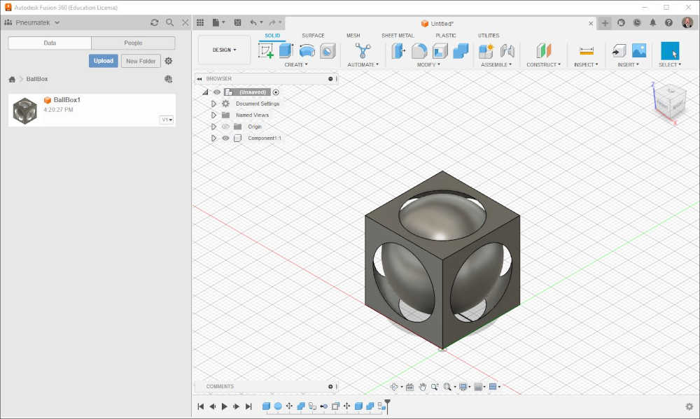
Slowly LMC the name to change it to BoxBall or RMC the name and use Properties to Rename it.

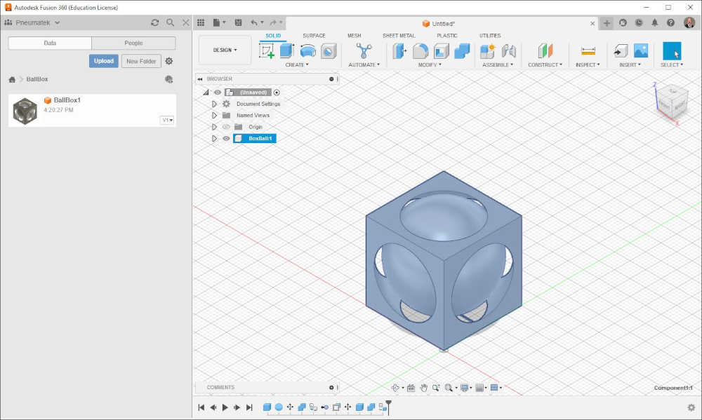
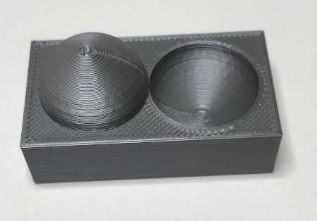
Save the File and Export BoxBall:1 as a STEP for use with PrusaSlicer (or whatever slicer you have). Saved the STEP file, imported it into PrusaSlicer, then exported it as .gcode. I had a gcode error due to the “connecting bar” protruding down 0.1mm instead of being embedded in the box as mentioned above. With this corrected, I printed it with Supports set at “For support enforcers only”. I thought that would do it.
Author’s NOTE: This prints fine at a 0.2mm layer. If you have sticking problems, try putting a few base supports on the sphere about 5mm from the base contact point.
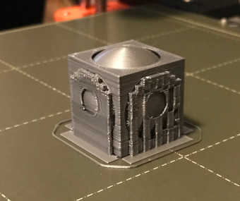
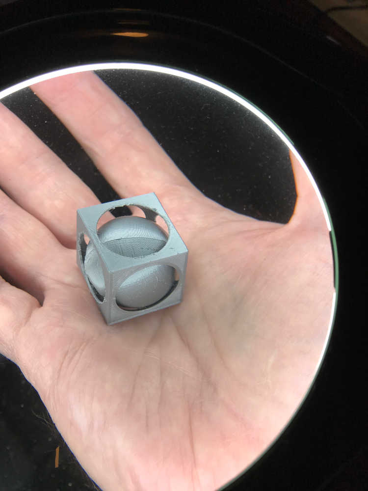
This was my first iteration:
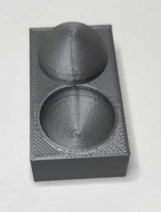
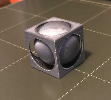
I decided to switch to silver filament after a print stop to figure out if it was printing properly…maybe a vision issue :) This is my second iteration:
Included your hero shots
- Included your hero shots:
Documented how you scanned an object
- Documented how you scanned an object:
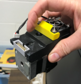
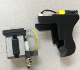
I conducted many experiments with 3D scanning equipment at the University; however, most were not satisfying to me. It may have been operator error or too little practice, but the least cost scanner produced my favorite result; maybe the content had me a bit biased. I hope you enjoy this.
Equipment used Matter and Form:
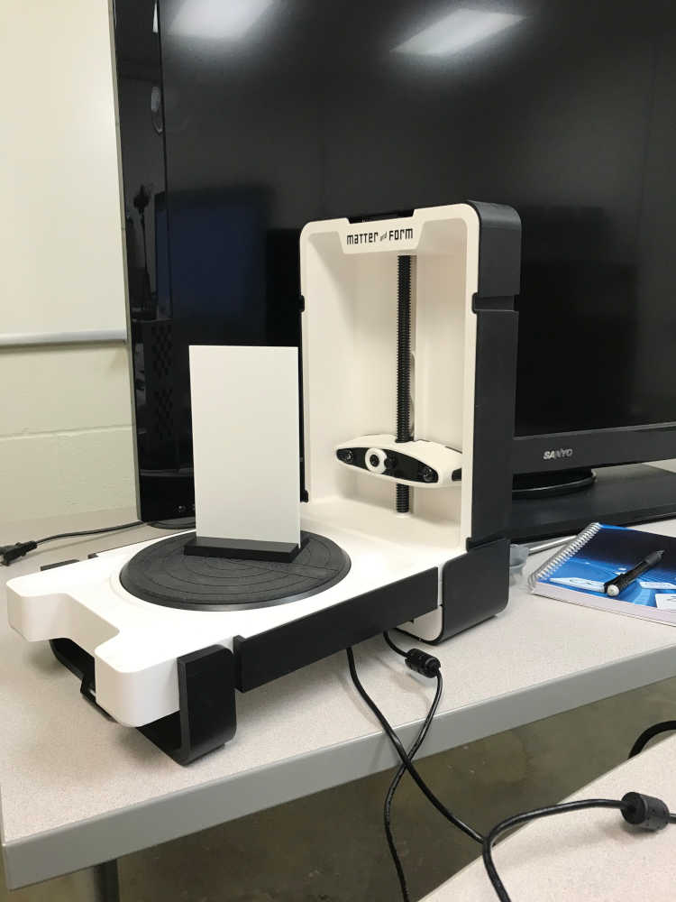
Scanning:
Output Video:
This is 3D Scanning documentation for Fab Academy 2024
-
I had a much better experience of 3D scanning with the advice of my instructor Pablo
-
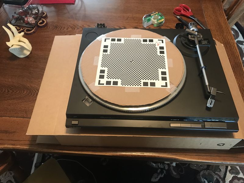
I used Qlone (Pronounced “Clone”) and loaded it on my iPhone 7 as an app. It does not require any hardware other than your phone. It can be loaded on an Android too :) However, I repurposed a Technics turntable to make scanning easier.
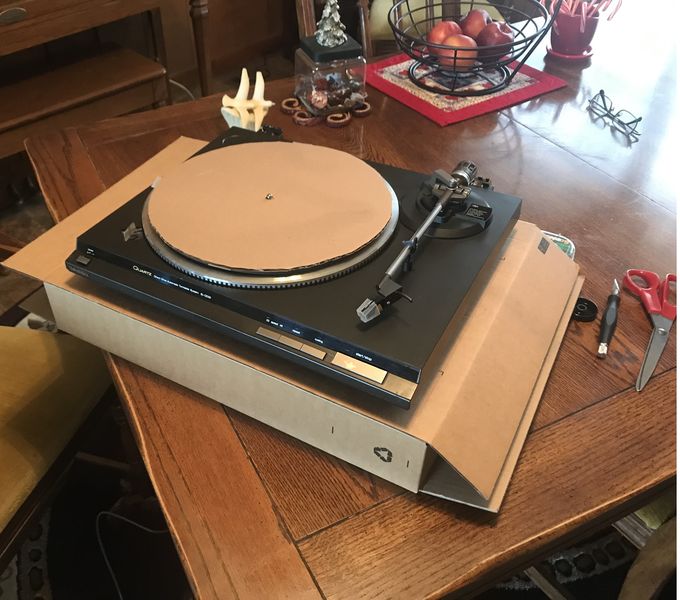
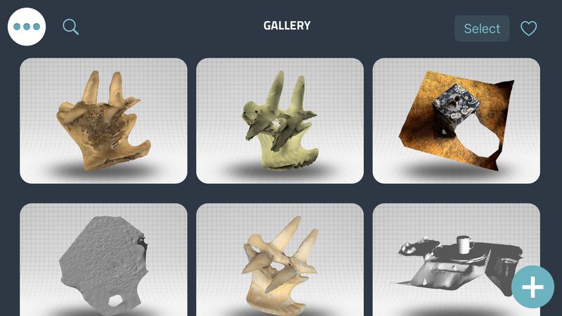
- This is the opening screen where you touch the plus sign in the lower right corner.
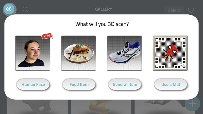
- This is where you select the type of scan. I will select General Item.
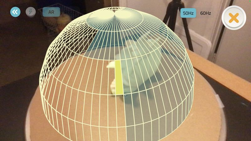
- This is the AR dome that shows up and you move around to properly place your item under the dome; then you touch the screen to place the globe.
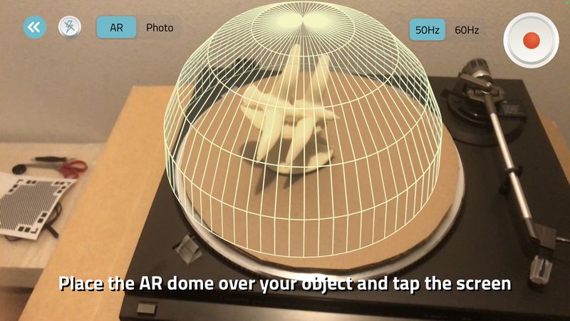
- Then you begin scanning with your phone while keeping the distance within the distance of the globe.
- Once the scan globe is complete, you can take close up pictures for more detail.
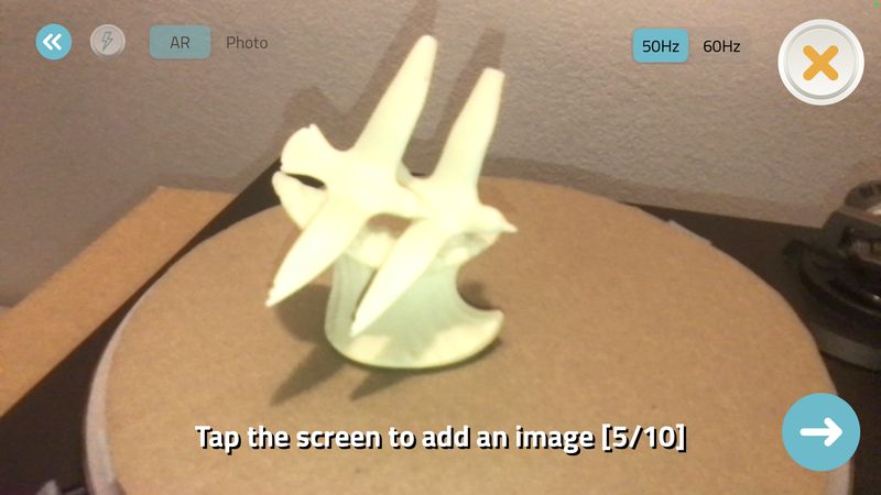
- Here is the final result after sending to the Qlone Cloud (Available with Qlone Premium) and exporting as a mp4 video and reduced for size.
The previous option without a Qlone mat is only available for Qlone Premium, but the free version requires a Qlone mat as shown below.
-
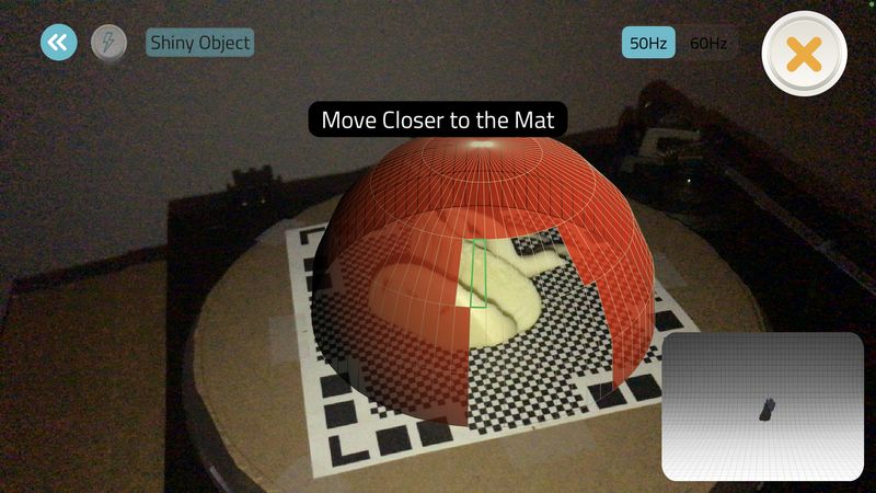
I used the same screens as before, but I chose “Use a Mat”
-
The size of the object is based on the size of the Qlone mat. Since the seagulls wings are tall, I had to lay the object on its side. In the below image you can also see the message “Move Closer to the Mat” in order to display the globe.
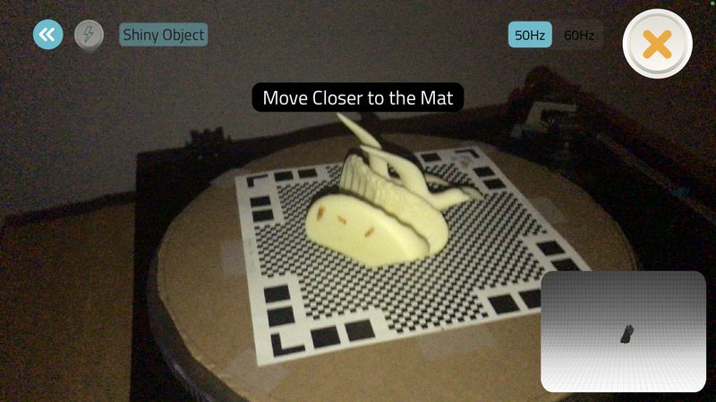
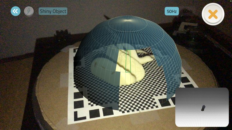
- I began scanning when my phone was at the correct distance by holding the phone still and rotating the turntable. This worked very nicely, but I would receive a warning if I moved too far away.
- The below image shows a good position with progress.
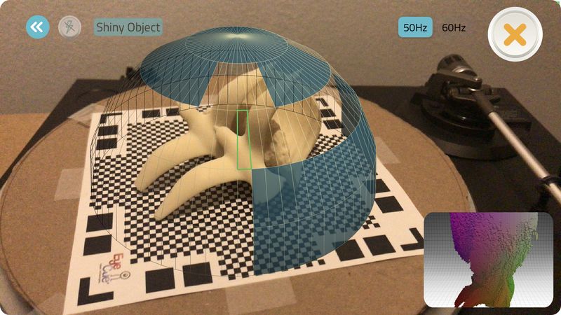
- Here is an image with more progress.
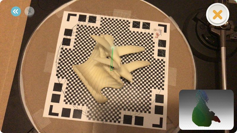
- This image shows the completed scan with the globe cleared.
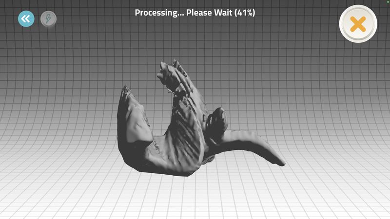
- I sent the scan to the Qlone Cloud and this is the screen while it is being processed. It doesn’t look very good as it rotates and it is a gray color. I thought it wouldn’t turn out very well.
- As you can see in the video, it turned out very nice.
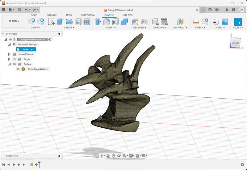
- I exported the model as STL and then imported into Fusion360 as a mesh. I had to manipulate it to get it oriented properly, but I was happy with the results.
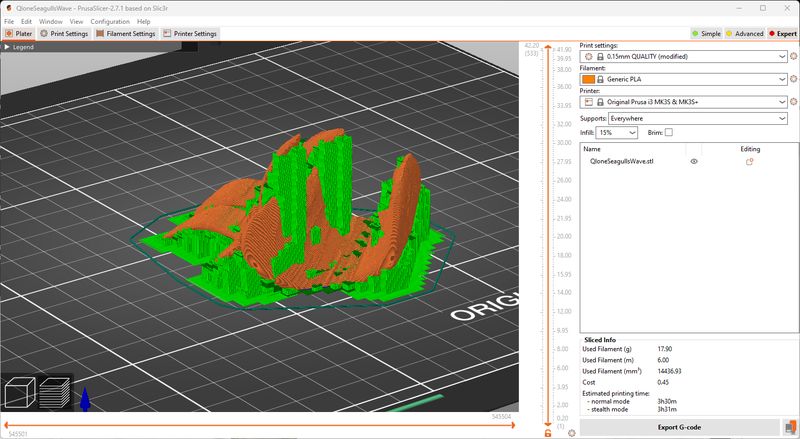
- I did not modify the model other than the orientation, but I decided to give 3D printing a try since I had time :) I imported the STL into PrusaSlicer as I did before and I had to orient it properly. The import turned out nicely, but I thought it would be a good idea to scale the size to 50%. I used white 1.75mm PLA filament provided by MiKA3D. I set the supports to Everywhere and used a 15% infill. The Gcode exported without any problem after I Sliced the model.
-
PrusaSlicer reported that it would take about 3.5 hours, so we will see what happens. It began printing the supports and I am excited to see what happens.
-
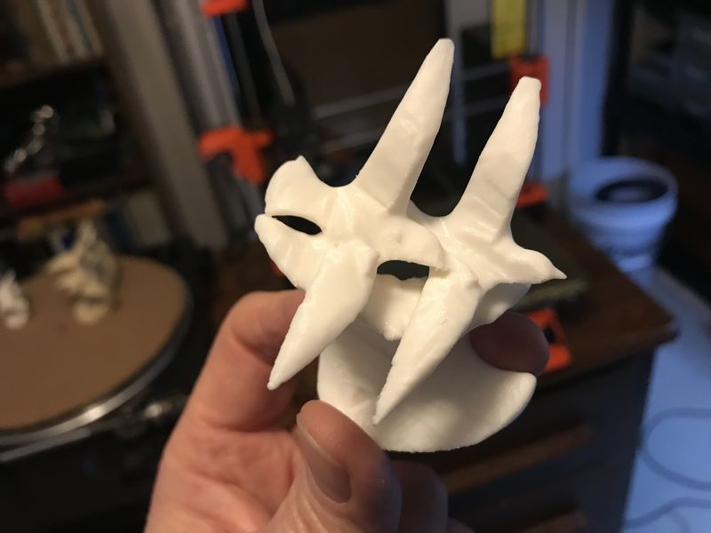
I am very pleased with the results of the print.
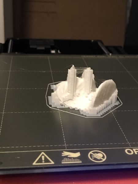
- Here is a better look before post-processing.
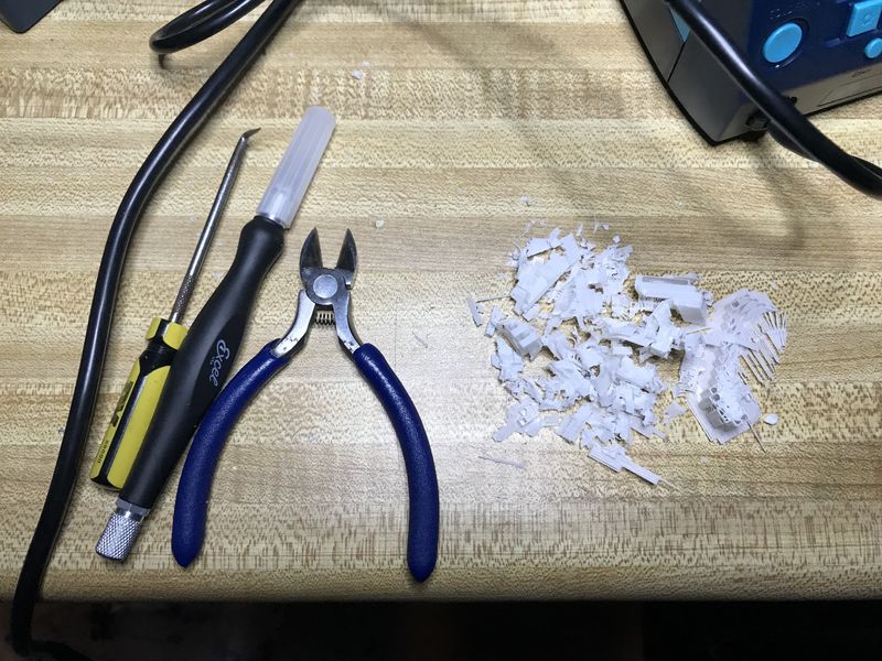
- Post-processed seagull wave.
- This is the remains of the post-processing.
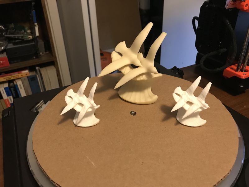
- And the hero shot of the results.
-
This was a very rewarding learning experience. The joy of capturing a 3D image with a scan and then printing a 50% scale model of the same thing is beyond words. You just have to do it to experience it.
-
The first attempt is the one on the left. I tried too hard to make it better and dug too deep during post-processing and I exposed the infill. Then I tried to fill in the hole, like soldering, by using a heatgun and some filament. I ended up getting the wing too hot and it started drooping. I made it look okay, but I had to print another one to feel better about the whole process. It is so cool to be able to just print another one :)
Research
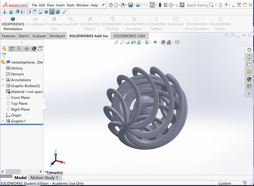
- Looked at models that were embedded spherical helixes, but wanted to embed a boat instead. Downloaded and viewed a spherical embedded helix as well as a boat, but need to learn how to build and integrate them.
Results
-
Description: Complete assignments and produce outcomes of Week 6 3D Scanning and printing.
-
Requirements: Described what I learned by testing the 3D printer; Show how I designed and made my object and explained why it could not be made subtractively; Scanned an object; Outlined problems and how you fixed them; Included your design files and ‘hero shot’ photos of the scan and the final object
-
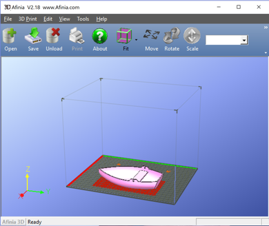
Planning: Using previous experience with the Afinia H800 3D printer, obtain files similar to the objective of the overall project.
-
Materials: Using current laptop, internet connection, and Afinia H800 3 D Printer. Use STL files obtained at Thingiverse to test the capabilities of the printer.
-
Problems: Due to lack of modeling skills, I will practice inserting other models into an existing model to result in an integrated model.
- Corrections: Found models similar to the goal of the project, so I printed them.
- Workflow: I used the Solid Works interface to bring STL files into my view. Manipulated the objects to explore how to change them. Found simplified models relateds to my final project and printed them.
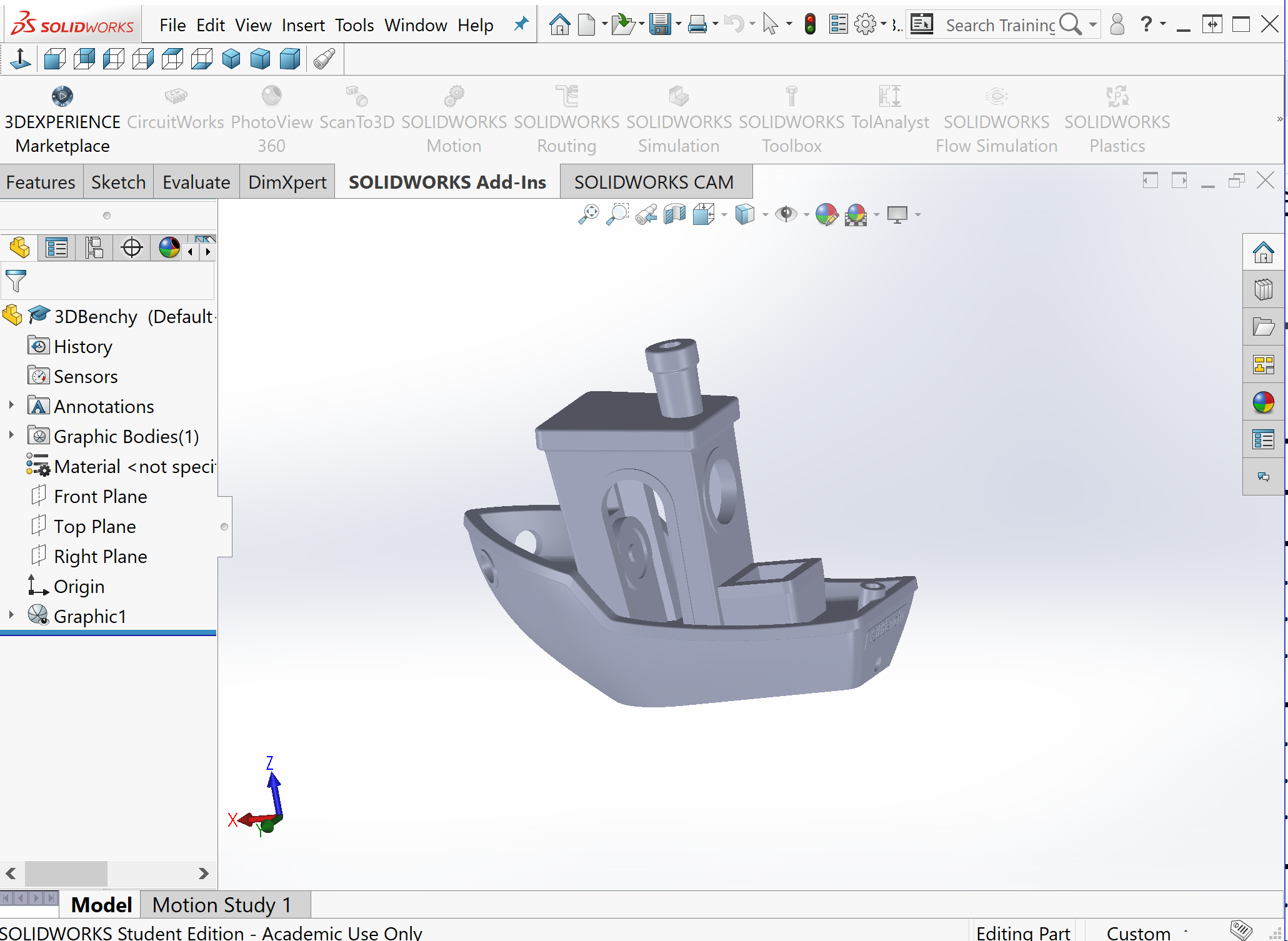
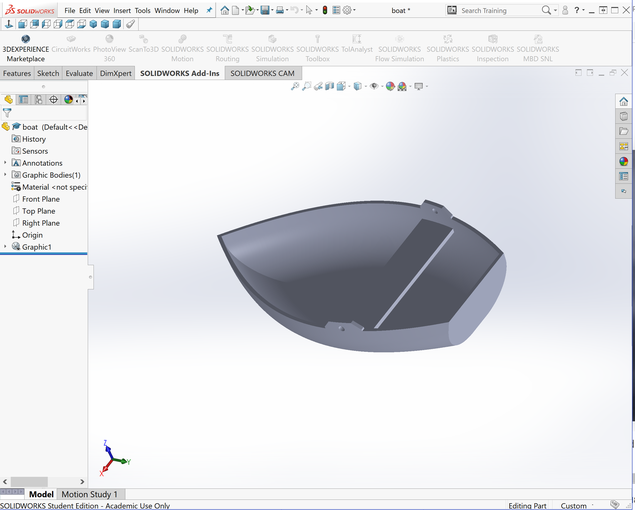
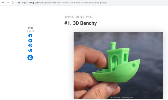
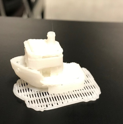
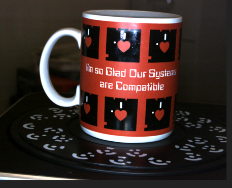
- Success: Printed the 3d Benchy to test the capabilities of the Afinia 3D Printer. Printed the boat file to demonstrate the required additive process due to the seat in the boat. Scanned a coffee mug, but I have much to learn about modeling the results of the scan.
-
Learning: I used several software applications to learn modeling: SolidWorks, xDesign, AutoCAD, and Fusion 360. I still have much to learn!
-
Using the Afinia H800 3D Printer is much easier, now, but there is so much more.
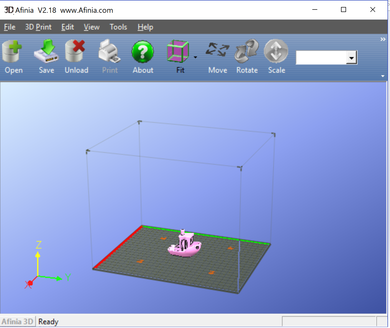
This is a continuation of the 3D Scanning and Printing week in Fab Academy 2020
- I downloaded the 3D Test from Thingiverse
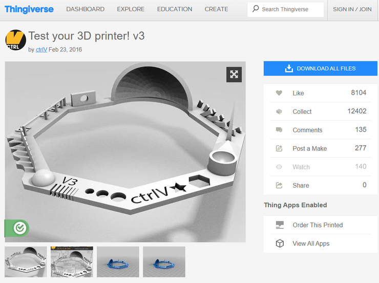
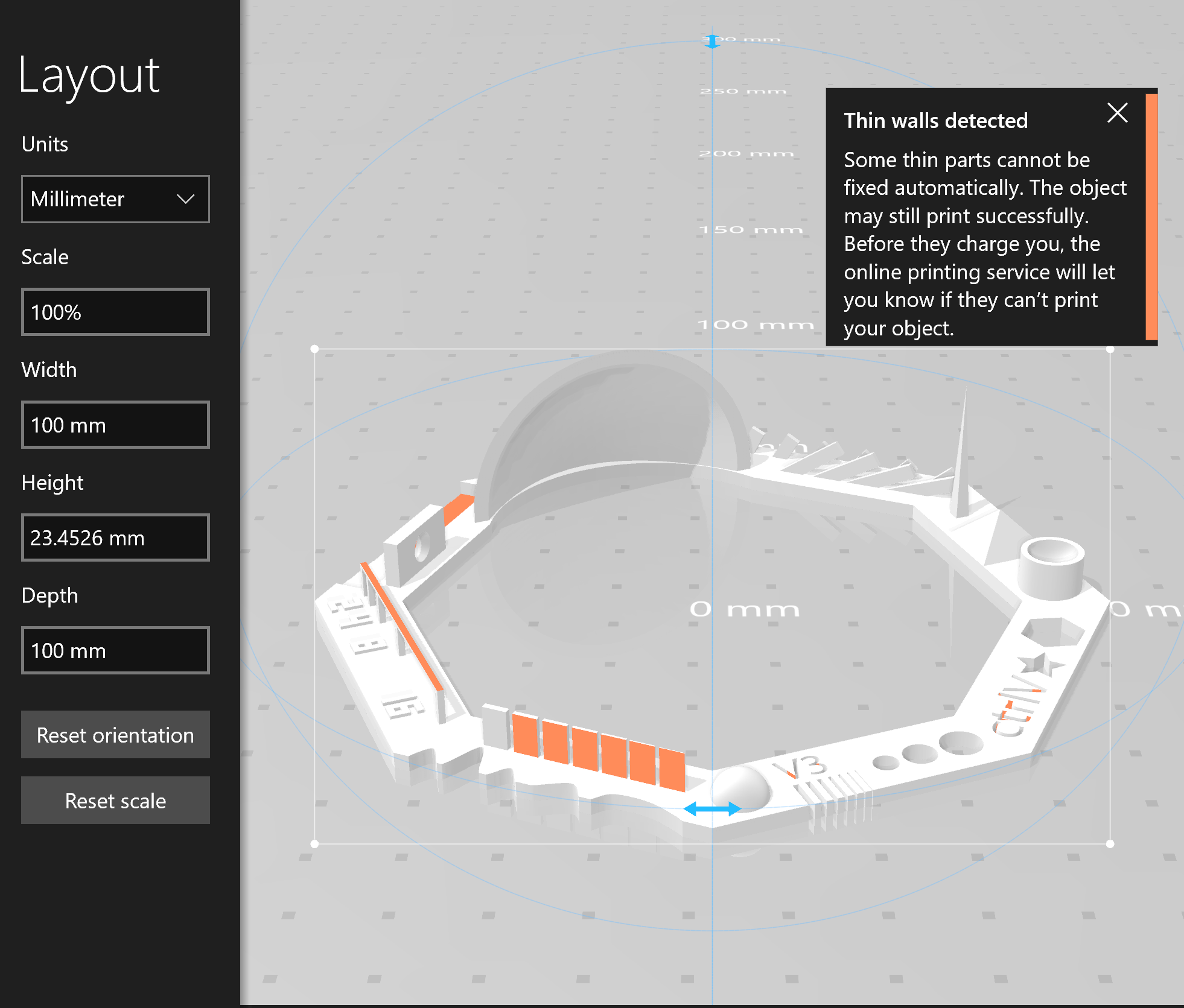
- I tried to print directly in Windows, but the 3D printer was not viewable in printers. However, when the software evaluated the model, it did warn me that thin walls were detected. I used the software provided by Afinia and it worked.
- So I tried the software supplied by the vendor of Afinia.
- Everthing seemed to be fine as the raft printed…
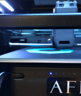
- I worked on other things as the print progressed until I checked the status…
- The print head was 0.5 inches from the part and still busy…FAIL. This is the result.
- So, like a good player, I started another print job…it did not satisfy.
- The material was not advancing…Time for debugging.
- Step 1. After reading the manual :)
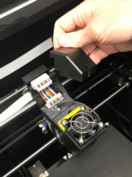
- Step 2.
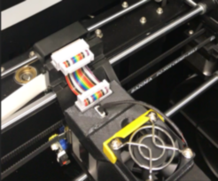
- Step 3.
- Step 4.
- Step 5.
- And finally Step 6 extruding properly.
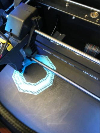
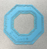
- Next print run produced a good part…
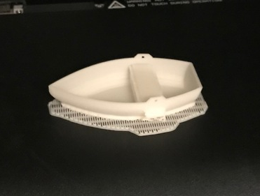
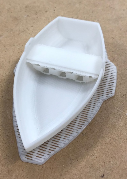
- This is a test part mentioned by @douwe.schmidt at Waag - Amsterdam Fab Lab https://www.thingiverse.com/thing:2806295 I will print this and see what happens with my new print head.
Final Remarks
-
After working with the Prusa i3 MK3S+ 3D printer, I can safely say that my initial 3D printing experience with the Afinia H800 3D printer was confounding to say it mildly. It was a very nice looking printer, but the experience did not feel like it looked. I’m sure a more experienced user would have done better, but I will stick with my Prusa.
-
Because the Afinia was completely enclosed for a controlled temperature environment, it added to the difficulty of use. I could not watch the process of printing to see if everything was working okay. However, the Prusa is completely open and viewable from all angles. Using a heated bed is a much better idea than keeping the air warm inside of an enclosure.
Included your original design files for 3D printing
- Included your original design files:
Design Rules FreeCAD
-
Modified Neil’s file, so I could print the infill design rule test with 0% infill_0.FCStd 26 Kb
-
Modified Neil’s file, so I could print the infill design rule test with 50% infill_50.FCStd 49 Kb
-
Modified Neil’s file, so I could print the infill design rule test with 100% infill_100.FCStd 48 Kb
Design Rules STL
CNC Mill Impossible Fusion 360
CNC Mill Impossible STEP
CNC Mill Impossible PrusaSlicer
CNC Mill Impossible gcode