Computer-Aided Design
This week I learned about graphic design, CAD, and modeling. This included:
Unit Description
- Model (raster, vector, 2D, 3D, render, animate, simulate, …) a possible final project, and post it on my class page.
Learning outcomes
- Evaluate and select 2D and 3D software
- Demonstrate and describe processes used in modeling with 2D and 3D software
Checklist
-
Description: Complete assignments and produce outcomes of Week 3 Computer-Aided Design.
-
Planning: I thought about using Photoshop and Illustrator for 2D and AutoCAD and FreeCAD for 3D.
-
Materials: Using current laptop, internet connection, and prior knowledge. Purchased a 3D model of a Laser Sailboat for $35 to test in the platforms that I installed
-
Problems: I had difficulty choosing the correct format, so I tried all of the models.
-
Corrections: I installed 3dsMax, AutoCAD, FreeCAD, ImageMagick, Inkscape and Sketchup. I used the FBX, OBJ, MAX, and SKP files to see how they would load. I realized that I had previously installed Fusion 360 when I was getting ready for Fab Academy, but it had fell into disuse; I have picked up that tool again and it is probably my tool of choice
-
Workflow: Downloaded and installed 3dsMax, AutoCAD, FreeCAD, ImageMagick, Inkscape and Sketchup. Experimented in each of these applications. Learned to use ImageMagick to reduce the size of the images for web use.
-
Success: I was able to open all files and manipulate them in the applications. The Sketchup file was free, but still a good lesson. I also have an ebook on Safari, Make: Design for CNC by Gary Rohrbacher, Anna Kaziunas France, Anne Filson with models available; I was reminded when I did a search for a book for Fusion 360 and I found Make: Fusion 360 for Makers by Lydia Sloan Cline. These authors are a great help!
-
Learning: I immersed myself in Fusion 360 by following a youtube tutorial by a guy who wanted to help people model a wooden boat, titled Fusion 360: How to design a Wooden Boat - Part01. I tried to follow along, but it was difficult due to the shortcuts he knew and used without saying everything he did. Don’t get me wrong, he is awesome! But how do you tell somebody how to do something that is tacit or reflexive in your workflow; believe me, I understand. So I worked through the basic training in Autodesk’s Fusion 360 website. Much to my delight, there was a tutorial on modifying a model of a canoe. Sweet! I discovered it when I saw a canoe as an asset, so I dug through the Hands-on exercises until I found “Modifying existing features”. I successfully completed the tutorial and hope to use my newly found boat modelling skills for the final project.
Modelled experimental objects/part of a possible project in 2D and 3D software:
-
Modelled experimental objects/part of a possible project in 2D and 3D software:
-
This is Autodesk’s image

- This is the model before editing

- This is the model after editing in Fusion 360

- The long awaited views of a Laser sailboat profile and deck in the 3D environment of Fusion 360. This model provided by Free 3D Models, but this one wasn’t free :) The Laser Class Sailboat model was Submitted by machine_men and was purchased by me with a Royalty Free License. I did not modify this model, I just wanted to see it for inspiration.


- This is the laser model after bringing it into Autodesk 3ds Max

- Next Step: Take scanned raster images of boat plans and make them into vector files.
This is a continuation of the CAD week in Fab Academy 2020
Shown how I did it with words/images/screenshots:
-
Shown how I did it with words/images/screenshots:
-
After the recitiation, I had a renewed appreciation of planning. Thank you, Norella and May! My time is so thin, that I must plan better in order to finish Fab Academy. I looked at the site made by Jobin Varghese at the Oulu Fab Lab and gained inspiration from his final project presentation. He shows the flow of work from start to finish with graphics. I combined this concept with Neil’s concept of spiral development and expanded another layer of the Center for Bits and Atoms logo. I sketched it on note paper.

- I designed this 2D in Adobe Illustrator and intend to make a 3D model to use for this 2020 Cycle

-
To become more proficient in 3D design I downloaded and installed SketchUp Pro 2020. Although there is a free version, I wanted to invest in this software since it plugs into the workflow toward VCarve; this works well with the ShopBot.
-
I also gained access to the SketchUp Tutorials, an excellent source of learning and practicing.
-
First, I learned the basic drawing tools and was able to quickly get over the creative block I have pushed against for too long. This included 2D that quickely moved to 3D. I feel liberated!!


Walls and Door - SketchUp Pro 2020:
-
I also learned how to capture my screen video using Win+G to open Game Bar. I then compressed using ffmpeg in linux to upload the video to my repo and embed the above code to share it.
-
And made some windows!
-
Using my newly acquired SketchUp skills, I decided to turn the 2D Project Management widget into a 3D model.
-
Foundation

- Mounting sites

- Sphere development learning

- Make sphere and cube

- Copied and pasted spheres and cubes

- Continuing with the spiral development of the Project Management concept, I completed the design of the model in SketchUp and captured a flythrough.
-
This will be my goto place for things I learn with Sketchup
-
A huge discovery through several spirals was the copying of objects in SketchUp. While studying the eBook Make: Design for CNC by Anne Filson, Gary Rohrbacher & Anna Kaziunas France, I had to take a 3D model of a chair and lay the parts out on the prospective material. I had to copy the chair and then hide the original. Seems easy enough, Ctrl-C then Ctrl-V. Except that it is “by reference” and when I hide the orginal, they both disappear. Very frustrating! In short, you need to Explode the group after copying, and then Make Unique for both objects. Then you can assign them to separate layers (tags) to change their visibility.

- During rotation using the Rotate tool, be sure to select the corner dot touching the face of the material and then rotate on the same plane; this keeps the part on the plane of the material.

- The part will snap to the horizontal plane; this makes it easier when you move them around.

- Move the parts around as necessary to place them in a good location with at least 1 inch clearance and 1 inch from the edge.

- This is all of the parts in a layout ready for flattening.

- 3D to 2D Transformation of the chair; videos to follow.

This is a continuation of the CAD week in Fab Academy 2021
-
As I studied the Fab Academy 2021 Assignments and Assessment, I wanted to add emoji images to My Experience in Fab Academy. It was a little spiral I wanted to try out. 💫 It’s good to review the requirements to see “How to be evaluated”.
-
I went to the page recommended in assessment and tried to use that code “:sparkles:” but it didn’t work in markdown. A Google search took me to a page where I could select the emoji as a character and I cold paste it directly into the markdown. That was too easy 😃 Another page took me to a site where I could click the emoji and it let me copy it by clicking “copy”.
-
Since the schedule changed a little for this cycle, I decided to rearrange my program management widget to coincide with the new lineup. I used Adobe Illustrator as my tool, moved the words around, and repositioned wildcard week.
-
I also used gimp to scale the image from 4800 x 4800 to 1000 x 1000 and converted it from a png to a jpg with a quality of 50%. There is very little noticeable difference. The file size changed from 292 KB to 74 KB. I have always thought that png was smaller than jpg. This is a huge lesson learned. Thank you Neil! The damage is already done in my past work, but I will get it right from now on.

Modelled experimental objects/part of a possible project in 2D and 3D software:
Discover:
- I discovered the cardboard kayak through Instructables, dswaim did an excellent job of documenting his work. I do not have a large format laser cutter, so I knew I would have to improvise. dswaim provided the CAD drawing as well as a pdf.
Explore:
- I can open the files in Autodesk AutoCAD and Adobe Illustrator, so I explored the details of the files and determined that I could isolate each part and rearrange them on separate files. Since my laser cutter has a smaller area, I decided to reduce the size of the drawings to see how it would work. Thankfully, the scaling worked perfectly with the kerf of my laser power at 100%.
- Opened pdf in Illustrator and transformed -90degrees and place on a 12x6inch page. cardboard_kayak_12x6in.ai

- Designed a page with all frames isolated from the drawings at full scale. allfitframes.ai

-
Within Illustrator, Edit Artboards in Properties gives information about the size; this allows you to determine the size of your imported file.
-
My goal was to isolate each piece in the pdf so I could bring them into any CAD software and manipulate them for assembly into a 3D model. So, this is my next spiral. 💫
-
Starting with the pdf file, I isolated each area for further part isolation. I labeled them as bottomleft, bottomright, topleft, and topright. I save the exported files to my OneDrive, took a picture with my iPhone and manipulated them using gimp –> 1000 px, jpg, and 50%.
-
The bottomleft panel contains the seat of the kayak

- The bottomright panel contains a mixture of frames and runners; they are numbered and lettered respectively for assembly.

- The topleft panel contains a mixture of frames and runners; they are numbered and lettered respectively for assembly.

- The topright panel contains a mixture of frames and runners; they are numbered and lettered respectively for assembly.

-
Once I had the panels isolated, I began to parse them so that I had 1 runner on each panel; this will allow me to manipulate each part and import them into 3D modelling software. I will demonstrate the topright panel, since it has only 4 runners. I will list them alphabetically by name. After deleting all of the unwanted lines, I save the file, exported it form AI as a png, manipulated them with gimp, and added them to the repo.
-
toprightfit_F_BB

- toprightfit_F_HH

- toprightfit_GG_B

- toprightfit_HH_B

-
So you can see it is tedious, but I enjoyed it 😃
-
My next spiral will be to import them into modelling software and manipulate them there.
-
Just one more thing…I used Python Turtle Graphics to demonstrate spiral development

- Here is the code to make your spirals

Refine
-
I worked through the tutorials for FreeCAD and Rhino after having difficulties making the Illustrator files behave in these environments. I could import them, but I could not control the lines and turn them into objects. My goal is to parameterize them, but I need to learn more about CAD.
-
The tutorial for FreeCAD helped a lot, but I must say, I got very frustrated and discouraged. I spent the whole evening redoing the first tutorial about a dozen times 😖
-
First, I tried it in the Windows (Alienware) environment and I could not see the coordinates of the cursor; it was due to the tiny font as well as the color. I Googled it and found out the status bar displays the numbers too; however, they didn’t refresh and it was frustrating. I abandoned Windows and went to Linux/Xubuntu 😃
-
I installed FreeCAD and immediately had relief…I could see the coordinates of the cursor in realtime! I jumped into the environment and used my Windows system to display the tutorial. I still had problems and could not get my drawing to be fully constrained. My Windows system reported that there was a Rhino update, so I downloaded it while I worked. The update required a restart, so I did it. Upon restart, I had a memory mismatch error that I have never had; the message recommended reseating the memory. I had to rest, so I called it a night.
-
The next day, I reseated the memory. The Alienware is a laptop and that was troublesome, but I did it and the problem was solved. Due to the troubles I had in Linux, I decided to give Windows another try. I was able to get the second tutorial fully contrained, so I tried it in Linux. I was successful after a few tries. My biggest mistake was not thoroughly reading the .... manual. The author specifically said, “Note: don’t mistake the Coincident constraint for the Sketcher Point; while their icons are very similar, the latter has a larger icon; it adds a lone point in the sketch.” Yes, that is exactly what I did 😖 The confusion came from not reading and the icon in the tutorial was different that the one in FreeCAD. I have been debugged 😃
-
This was the “Simple” Part Design Tutorial result. Wasn’t to me, but now I know how 😎

- This was the “Basic” Part Design Tutorial results. I still have a way to go 🤓


-
Big takeaways for this week…stand on the shoulders of giants; you will see further than the seaweed you are in. Shout out to the Global Open Time! So encouraging! Namely, Adrian, Pablo, Rico, and Nanditha. Such great mentors and willing to assist.
-
The help from Rico was huge! The tutorial during global open time for parametric design was timely. It was recorded for all to benefit. Go to Mattermost to check it out.
-
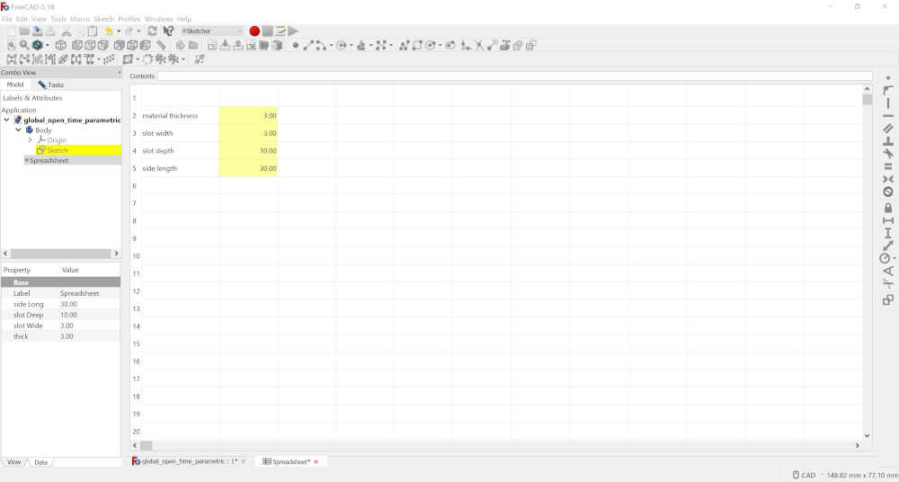
I made the parameterized triangle demonstrated by Rico. It took some time to get it fully constrained.
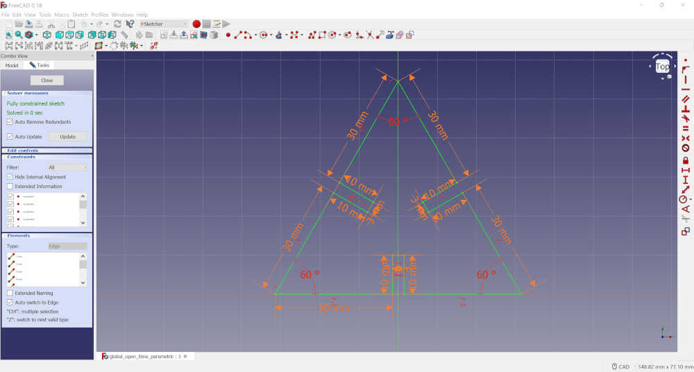
- Next, I will make a 3D model and send it to a laser cutter. I found a site https://youtu.be/ikip-g5qPhA and https://wayofwood.com/laser-cutting-cad-design-with-freecad/
This is a continuation of the CAD week in Fab Academy 2022
-
From previous Fab Academy cycles, I laser cut the press fit parts for the 1/4 scaled version of the cardboard kayak; this required using Adobe Illustrator, modifying the pdf file and sending as a print job to the Epilog Helix 24-75W 24”x18” cutting table. I then assembled the kayak. During this cycle, I took a picture of the assembled kayak and edited the image using GIMP in a raster 2D image.
-
This is the original image

- This is the cleaned up version of the image. I removed the background and replaced it with pure white using the eraser tool.

Break on through to the other side
Modeling has been a weakness I have struggled with from the beginning of Fab Academy 2019. Hence, the reason I have been through so many cycles. This is now Networking and Communications week in Fab Academy 2022. I am in a 40 day countdown plan to finish Fab Academy and I just revised this page with a checklist for ease of evaluation. As I was going through nueval, I read again from my instructor, “For this assignment the goal was for you to model a possible final project.” I became overwhelmed, again. I knew I had to get through this obstacle or never finish. So, I got out the modelling tool that has helped me in the past; although I did not model a final project, I did model what you saw above; this gave me hope, but I didn’t finish, again. Rico Kanthatham gave me great advice, given to him by his instructor, “overcoming those obstacles…will level me up sharply”. Well, it happened, I modelled the seat for the cardboard kayak today, second day into the countdown…
I exported the .svg file from Adobe Illustrator as a .dxf file.

Then I imported it into Sketchup.

The file imported just fine and I measured the length…14 inches. I measured the actual kayak…14 inches. Success! To make the sketchup model, I used the line tool and made lines from point-to-point until I made it around the whole image; this makes it an edge, that I was able to extrude and give it a thickness of 1/8 inch.

This is a quick 3D view of the seat model:
Once I had the workflow running well, I began to iterate more rapidly. Instead of tracing point-to-point, I found great help from TIG, a SketchUp Sage on this SketchUp Forum. Basically, draw a rectangle around the dxf shape, in the same plane, intersect the two, and then delete the outer edges of the rectangle. What a time saver!!
The following are screenshots of building the kayak deck:
Deck Assembly 1:

Deck Assembly 2:

Deck Assembly 3:

Deck Assembly 4:

Deck Assembly 5:

- To be honest, I made it to countdown day 35 and realized I could not finish during this cycle. Once again, I informed my instructor that I would be continuing in the 2023 cycle. I continue to work on my weakness so I can overcome this obstacle. I am working with Abby to complete the group assignments over the Summer. I will continue to work on individual assignments as well.
This is a continuation of the CAD week in Fab Academy 2023
-
I kept hacking at my design skills during the off-cycle time; this included modeling the kayak framing in Sketchup. The process was very tedious, but I continued until I had all frames aligned on the keel. It was not perfect, but it gave me a sense of accomplishment.
-
My workflow began in Adobe Illustrator using the scaled version of each part mentioned above. I exported the part in dxf format since that is the only file type that seemed to work best in Sketchup.


- Imported each file into Sketchup.


- This is how it came into Sketchup in the proper orientation along the x-axis.


- I selected the object after saving it in Sketchup format.

- I drew a rectangle around the object in preparation to intersect the faces and delete empty faces.


- Then I deselected the object in preparation to delete the empty faces and the border rectangle.


- Now I have the object in Sketchup and able to modify the thickness by extruding.


- I follow the same process for the remaining objects and manipulate them to assemble them together. I include the remaining objects in the following images.


- This was a lot of work, but I wanted to bring it into Fusion 360 to see how it flows.


- I exported the file as 3ds to see how it would import. I placed it here for your viewing pleasure 😎
-
Hope you enjoyed the ride!
-
Now I need to render this ride. White Oak is one of the best waterborne woods, so so I’ll apply that to the keel and frame.
-
I selected the Render Workspace.
-
With the centerline assembly in Fusion 360, I selected all of the bodies by dragging a rectangle around all of them in the viewing window.

- Clicking on Setup >> Physical Material >> Open Wood Folder >> Click and Drag White Oak onto the selected bodies.

- And here is the Fusion 360 link so you can check it out:
-
I was able to share this with my granddaughter…she said, “thats sick :) it looks great!” 😎
-
Now I must model the propulsion pod that will sit in the kayak and produce wind toward the stern to push it forward (or pull it; depending on your perspective :)
-
This has been a real learning experience due to my minimal design skills. However, I used my documentation to break through the creative mindstorm I have been stuck in for some time. So here it goes!
-
I had previously isolated the cockpit of the kayak, so I will use it to make the propulsion pod.
-
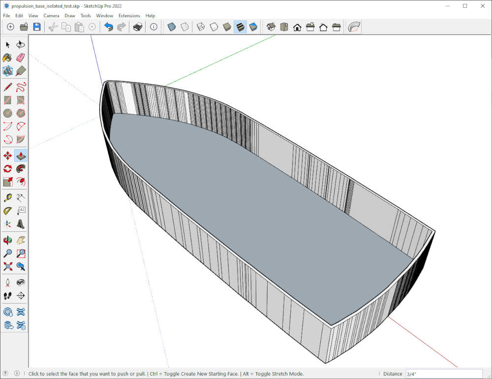
Using my above documentation for intersecting faces, I do the same process to extract the shape.

- Then I delete the outer surface and the rectangle, leaving the boat shaped surface I was after.

- I trim the tabs by drawing a line connecting the endpoints to separate the surfaces and delete the unwanted surface as well as the lines. In the Menu > Draw > Lines > Line then Click on the endpoint at the beginning of the tab, then Click on the endpoint on the other side. This will make the line you can see in the image below. Now switch to the Select Tool by pressing the Spacebar. Click and drag a selection rectangle around the isolated tab, Right-Click and erase. You will need all segments of the lines and erase them until they are gone.


- The video below shows the trimming process.

- I used the Offset tool and the Push/Pull tool to make the hull of the object 1/16” thick and 1 1/4” tall. A video is better than a picture.
- Then I exported it as a 3ds file and imported it into Fusion 360 for your viewing pleasure.
Propulsion! Jim! We need more power!!!
-
I will spare you the details of modeling in Sketchup; although I did have fun.
-
I took the original boat shape and gave it dimensions so it would fit on top of the boat above. I will give you a screenshot

- Then I exported/imported to Fusion 360. I hope you feel the power!
-
Finally, I would like to document my activity using Unreal Engine to simulate a water environment to float my boat! 😎
-
I have completed this process before, but I used a boat designed by the plugin author. So here it goes.
Water Physics in Unreal Engine
- Start Epic Games Launcher > Launch Unreal Engine 5.1.0 > install the dynamic water physics plugin through the Epic Games Launcher

-
Created Game in Unreal Editor and called WaterPhysics5_1 > Once opened I was informed that my system is Missing support for advanced rendering features > “This project attempted to launch DirectX 12 with the SM6 shader format but it is not supported by your system.” (This is due to the lower power capability of my single-board computer. I previously did this on an earlier version of unreal engine.)
-
Launched Unreal Engine 4.27.2 > I received the following message: “You are using a trial version of Dynamic Water Physics. To use this plugin in a released product you must purchase a full license at: https://www.unrealengine.com/marketplace/en-US/product/2d8710643bcf4e2b94a9154d0732b4af”
-
Since I installed the water physics plugin to the 5.1 engine, I needed to install it to the 4.27.2 engine as well. However, I still got the trial version message. I deleted the WaterPhysicsTrial folder from the Plugins folder in D:\Epic Games\UE_4.27\Engine\Plugins. When I started the engine again, the new Dynamic Water Physics (1.3.13) plugin showed up in the Plugins > I no longer receive the trial version message.
-
The new plugin is placed in D:\Epic Games\UE_4.27\Engine\Plugins\Marketplace\WaterPhysics
-
This is the website to read about the plugin
-
This is the youtube video to make a boat in a water environment
-
Created Game in Unreal Editor and called WaterPhysics4_27_2 and verified Dynamic Water Physics plugin was enabled as well as the built-in Water plugin
-
Deleted Floor and SphereReflectionCapture

- Let’s add a landscape since the new water system requires you to have a landscape Modes to Landscape (Begins compiling Shaders)

- Let’s just fill the world Click Fill World

- And do not forget to enable the edit layers otherwise the water will not work Check the Enable Edit Layers Checkbox

- Let’s create it Click Create(Lighting needs to be rebuilt)

- Take it out of Landscape mode

- In the Place Actors tab, search for ocean and drag Water Body Ocean into the stage

- Waiting for the shaders to compile… While I waited, I updated my Prusa firmware > Parallel Development!! Thanks for the BootcampTimeManagement Rico 😎

-
Here’s some beautiful water!
-
Turn off the static lighting for this > Go from Static to Movable with the Light Source in the World Outliner, since this is optional

- Let’s save this level let’s call it our boat level > File > Save All Levels > BoatLevel

-
Time to watch the sunset… See you next time! 😎
-
This is a quick video of the water physics in action.
This is a continuation of the CAD week in Fab Academy 2024
-
My Remote Guru, Pablo, pointed out some improvements I could make in my repo, so I worked on those this week. One of my weaknesses is documenting as I go. Using VSCode makes it so much easier! I had already improved the layout by removing the numbers, so making these changes is much less stressful. It’s kinda like debugging. Speaking of debugging, I got attacked in my Personal Fab Lab by a wasp while I was making this change. It landed on me and stung me multiple times on the back and went and hid somewhere. I got my handheld DynaZap Bug Zapper and layed it on the table beside me and continued working. The culprit returned on the desk beside me ZAP! Now we’re even :) VSCode is kinda like DynaZap and makes debugging so much easier.
-
The changes I made are seen above, but I will list them here to help you find them and benefit by them:
-
I gave credit to the maker of the Laser Class Sailboat model I showed. I also added links to the people I mention by including a link to their pages.
-
I recorded the change I made to demonstrate how I trimmed the tabs from the boat shape in SketchUp and included a video too.
-
I recorded the change I made to demonstrate how I added sides to the boat shape in SketchUp and included a video for that too.
-
Lastly, I am documenting how I designed a logo for my new Personal Fab Lab. As a background story, the logo for the GOCAT Fab Lab was designed by Tom Wood for me when I first built the GOCAT Fab Lab. He said I needed a “kickass cat” for my lab and he did not disappoint. As you may/or may not know, I left the University so I could continue/complete my studies in Fab Academy, so the GOCAT is no longer a “going concern”, but the “cat” who made the GOCAT Fab Lab is still going :) So you will get to see how I made some changes to make a new logo.
-
-
I wanted to use the FireCat, but the name had to change. My original attraction to Fab Academy was the idea of building a boat using digital fabrication. Soooo, I thought of FABCAT and made a domain name to match. As a disclaimer, I discovered that there is another FabCat Fab Lab, but they are located in Catalonia and I am located in the United States; hence the domain name FABCAT.us. We are not competitors and have not met, but I hope we meet some day. My Fab Lab is focused on boats and their automation, so the name FABCAT is an acronymn for Fab Academy Boat-Centered Automation Technology in the USA.
-
Okay, now that we have that explained, let’s get on with the design.
-
I have asked Tom Wood for assistance, but I thought I would give it a try with the tools I have. My design skills are still budding, but this will help them grow. My tool of choice is Adobe Illustrator. Tom uses this tool to design and I have learned a lot from him over the years since the late 1990s. So I will start there. The below image was obtained by copying it in Illustrator and pasting it in Photoshop; this was automatic and pasted in pixels or a raster image. I studied it and made the following sketch followed by the idea of what I was hoping for.


- I spent the better part of the day trying to modify the GOCAT Fab Lab logo. I started by isolating the letters and making copies and then pasting them for modification. I Reflected the letter A and trimmed it to look like an F. Then I resized the O and stacked two of them to make a B. I wasn’t real pleased with the B, but it was what I had. It was really experimental and I had no idea where it was going, but here is the result:

-
I learned a lot by trial and error and capturing that would have been difficult without a GoPro, but here is the basic workflow I used in Illustrator:
- I isolated GOCAT and copied letters and positioned them, reflected and trimmed the A to make the F, then scaled and stacked the O to make the B. I also changed the size of the holes and filled them to match the background colors.

-
The next step was to make the background layers. This is where I tried many things by dragging anchor points, making line segment, copying and pasting parts of the graphic, etc., etc. Till I was very frustrated. At one point a Quick Actions button showed up for Offsets and I saw it… and thought, maybe there is an easier way.
-
In my morning emails I was reminded of the ability to find fonts from a picture, so I gave that a try.

-
I used What Font Is and found the exact font in the logo. I downloaded it, extracted it, Right-Click on the file and it was Installed in Windows; and better yet…it was available in Illustrator. Now things got fun.
-
First I typed the FABCAT in 72 pt letters, then Cary Hawkins showed me how to outline the letters by selecting then > Type > Create Outlines

- This is the result:

-
As you can see in the image, I have a few layers where I have been experimenting. I will show you the process. Now a little color control.
- As I learned from Tom Wood, it is good to have a palette of the colors you will be using. To be honest, I didn’t do this till many iterations of having to type in the color; but it’s all good now. I will be able to use the eyedropper to sample the colors as needed.

- Now to change the color. Select the letters with Direct Select, then change the tool to Eyedropper, Click the color, and ZAP!, the color changes.

-
The B is still a little off for my wife’s liking, so I am going to make some modifications:
-
First, the upper right corner needs to match the lower. After several attempts, I found just the tool. Click outside of the shape, then Click the anchor point in the upper right. Under Properties to the right, Click Corners, Select Chamfer, and I used 0.125 in. It worked as I hoped :)
-
The stem needs to be extended to match the other letters with stems. Click outside of the shape, then Click the anchor points in the lower left while pressing the Shift key; this selects the line; Click and drag it down until it matches the others. It is matched when the Intersect indicator shows.
-
Finally, I need to expand and close the gap at the bottom. Click outside of the shape, then Click the anchor points in the lower left, for the bottom of the B while pressing the Shift key; this selects the line; Click and drag it to the left until it touches the vertical stem. It is matched when the Intersect indicator shows.
-


- One last touch to the B. Click outside of the shape, then Click the anchor point in the upper right corner of the opening in the B; this selects the corner and the angle; Click Corners, Select Chamfer, and I used 0.125 in., but it wisely made it 0.0312 in. It worked as I hoped :) I think we’re good now!

-
Now I have to make this look 3D as Tom showed me. I will work toward the back; middle first.
-
I made three copies of the finished product so I could modifiy them. Select the layer under Layers, hold the Alt key and drag three copies to the bottom of the stack. Renamed them accordingly.
-
Give me a B! What’s that spell? FABCAT!
-

-
The next step is the middle layer.
-
Hide the other layers and Select the middle layer copy.
-
Use the Direct Select to select all letters. Then > Object > Path > Offset Path… I made this one 0.04 in. Miter, Click OK.
-

-
Color change.
- To change the color for the middle layer, use the Direct Select to select all letters. Select the Eyedropper tool and Click on Red.

- Now for a progress check. Just turn on the top layer. Sweet!

-
The next step is the back layer.
-
Hide the other layers and Select the back layer copy.
-
Use the Direct Select to select all letters. Then > Object > Path > Offset Path… I made this one 0.08 in. Miter, Click OK.
-

-
Color change.
- To change the color for the back layer, use the Direct Select to select all letters. Select the Eyedropper tool and Click on Black.

- Now for a progress check. Just turn on the top layer. Whoa! How cool is that?!

-
And now, for the finishing touches. We need a cat and we need a place. I will copy and past them into the last image.
-
What I have been dreaming about came true tonight. What a ride!

Hero Shot!

Included your original design files:
-
Included your original design files:
-
This is a list of my original design files discussed on this page:
-
2D Raster
-
Adobe Photoshop
-
Original Lettering of GOCAT Fab Lab gocat_lettering_original.psd 350 Kb
-
Lettering of FABCAT Fab Lab V1 fabcat_lettering_v1.psd 386 Kb
-
Lettering of FABCAT Fab Lab V2 fabcat_lettering_v2.psd 305 Kb
-
FABCAT Final fabcat_final.psd 567 Kb Mb
-
GIMP
-
Original Picture of Cardboard Kayak IMG_4743.jpg 1.3 Mb
-
Edited Picture from GIMP kayak_clean.xcf 255.9 Kb
-
2D Vector
-
Adobe Illustrator
-
Project Management Widget projectmanagementwidget2020.ai 1.2 Mb
-
Cardboard Kayak allfitframes.ai 57.6 Kb
-
Cardboard Kayak cardboard_kayak_12x6in.ai 1.3 Mb
-
Cardboard Kayak Seat bottomleft_seat.svg 27.3 Kb
-
Cardboard Kayak Seat Exported bottomleft_seat.dxf 125.4 Kb
-
Lettering of FABCAT V1 fabcat_lettering_v1.ai 1,271 Kb
-
Lettering of FABCAT Fab Lab V2 fabcat_lettering_v2.ai 1,246 Kb
-
Python Code
-
Spiral Development circles.zip 555 b
-
3D CAD
-
Sketchup
-
Walls and Door Walls_and_Door.skp 103.7 Kb
-
Windows Windows.skp 110.7 Kb
-
Project Management Widget PM.skp 644.5 Kb
-
3D Chair (Sketchup) to 2D Vector (Illustrator - Inkscape) D4CNC_Chair1_25percent_24x12.ai.svg 50.2 Kb
-
Cardboard Kayak Seat Model seat.skp 41 Kb
-
Cardboard Kayak Deck Assembly deck_assembly_5.skp 770.2 Kb
-
Fusion 360
-
Centerline Assembly Rendered in White Oak centerline_assembly_14_v1.f3d 562 Kb