Networking and Communications
This week I will learn about networking and communications. This will include:
Unit Description
Group assignment:
- Send a message between two projects
- Document your work to the group work page and reflect on your individual page what you learned
Individual assignment:
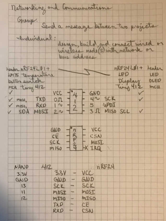
- design, build, and connect wired or wireless node(s) with network or bus addresses
Learning outcomes
- Demonstrate workflows used in network design
- Implement and interpret networking protocols and/or communication protocols
Checklist
Linked to the group assignment page:
-
Linked to the group assignment page:
-
There are two types of assignments, one group and one individual, since I am alone in my personal Fab Lab I will do both. All of my work will be documented here, so there won’t be a group assignment page.
-
Send a message between two projects
This is probably one of my favorite assignments due to having a lot of experience with networking and communications. My navy experience began with learning basic electricity and electronics followed by interior communications electrician school. At the time, wireless communications was only communicating with the world outside of the ship using radios. Shipboard communications were all wired communications, announcing systems, and face-to-face. Networking was achieved through wired networks until fiber optics arrived.
It is difficult to tag each moment of learning, programming processes, and problems solved because they are interrelated, integrated and occur throughout this learning experience. Therefore, I am listing these requirements at the beginning to let you know they occurred in various order throughout; I hope you enjoy the experience like I did :) I’ll do my best to document what happened.
Documented your project and what you have learned from implementing networking and/or communication protocols:
- Documented your project and what you have learned from implementing networking and/or communication protocols:
Explained the programming process(es) you used:
- Explained the programming process(es) you used:
Outlined problems and how you fixed them:
- Outlined problems and how you fixed them:
Wired
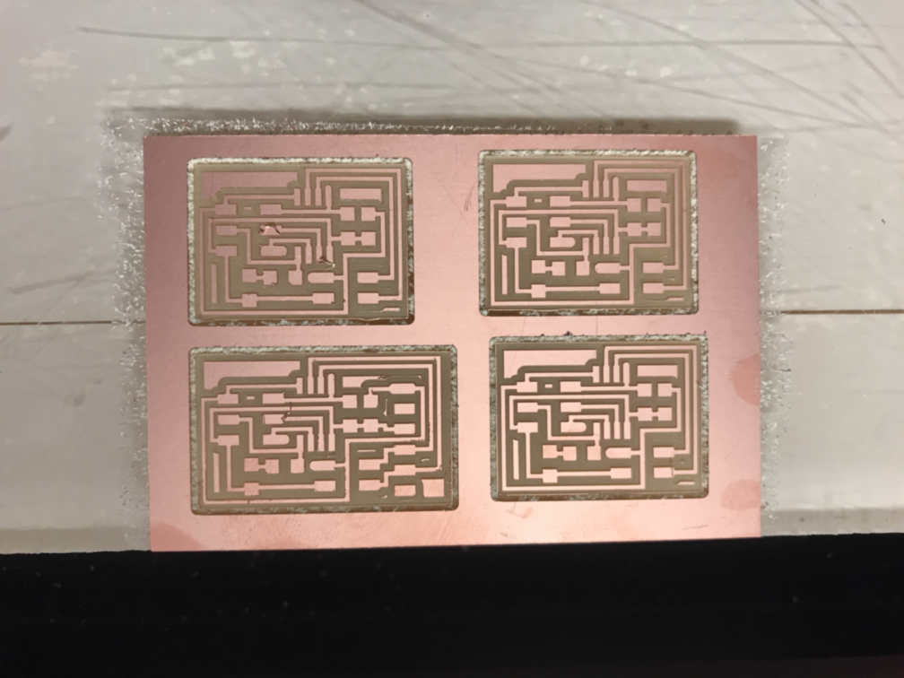
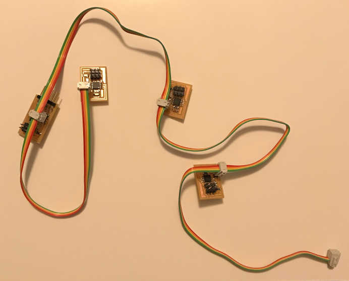
My first project for this assignment occurred during my Fab Academy 2019 cycle when I imitated Neil’s work to build the hello.bus.45.bridge and the hello.bus.45.nodes. Since I was still lacking in design skills (at the time), I decided to use the traces provided by Neil to improve my fabrication process as well as learn about networking and communications. Since this assignment is to send a message through two projects, I document this learning experience as part of the assignment.
I will provide images and files that were collected and used as well as videos to show the communications occurring.
- Made serial bus bridge and 3 nodes
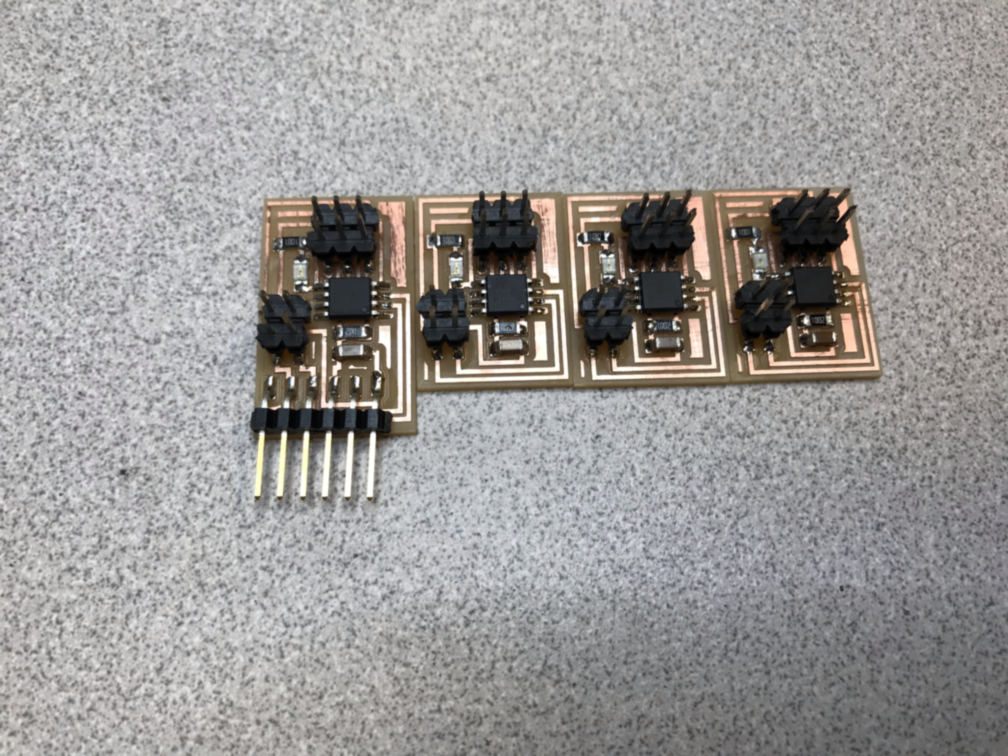
- Programmed boards
-
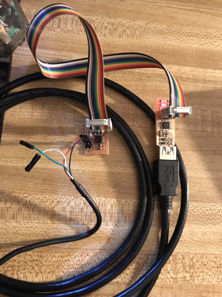
I used a linux system, my USBtinyISP, make, and avrdude to program the boards. Make produced the .hex file that avrdue sent to the bridge and nodes through the USBtinyISP
-
The bridge board had power through the TTY cable, but I had to provide a power source to the node boards using a USB adapter.
Code Example
jimhart@jimhart-Xubuntu2:~/serialbus$ sudo make -f hello.bus.45.make
[sudo] password for jimhart:
avr-gcc -mmcu=attiny45 -Wall -Os -DF_CPU=8000000 -I./ -o hello.bus.45.out hello.bus.45.c
avr-objcopy -O ihex hello.bus.45.out hello.bus.45.c.hex;\
avr-size --mcu=attiny45 --format=avr hello.bus.45.out
AVR Memory Usage
----------------
Device: attiny45

Program:     766 bytes (18.7% Full)
(.text + .data + .bootloader)

Data:          4 bytes (1.6% Full)
(.data + .bss + .noinit)


jimhart@jimhart-Xubuntu2:~/serialbus$ sudo avrdude -p t45 -P usb -c usbtiny -U flash:w:hello.bus.45.c.hex

avrdude: AVR device initialized and ready to accept instructions

Reading | ################################################## | 100% 0.00s

avrdude: Device signature = 0x1e9206 (probably t45)
avrdude: NOTE: "flash" memory has been specified, an erase cycle will be performed
         To disable this feature, specify the -D option.
avrdude: erasing chip
avrdude: reading input file "hello.bus.45.c.hex"
avrdude: input file hello.bus.45.c.hex auto detected as Intel Hex
avrdude: writing flash (766 bytes):

Writing | ################################################## | 100% 1.15s

avrdude: 766 bytes of flash written
avrdude: verifying flash memory against hello.bus.45.c.hex:
avrdude: load data flash data from input file hello.bus.45.c.hex:
avrdude: input file hello.bus.45.c.hex auto detected as Intel Hex
avrdude: input file hello.bus.45.c.hex contains 766 bytes
avrdude: reading on-chip flash data:

Reading | ################################################## | 100% 1.34s

avrdude: verifying ...
avrdude: 766 bytes of flash verified

avrdude: safemode: Fuses OK (E:FF, H:DF, L:62)

avrdude done.  Thank you.

jimhart@jimhart-Xubuntu2:~/serialbus$ sudo python term.py /dev/ttyUSB0 9600
- Tested serial bus communications. Communicated through terminal using TTY cable.
So far, I found that I only needed to change the node_id and nothing else in the code.
I flashed all of the boards with the address of “0” and they are all double flashing when I push “0”. I reprogrammed them with the proper address and they will double flash when their respective number is pushed, but they still double flash when “0” is pushed. Only “node 1” is displayed in the terminal; the other node responses are not displayed.
I decided to erase the chips and start over. I erased “0” first; it does not single, or double flash anymore, but the other boards do through the serial bus cable using the TTY cable. Very cool!
So, I recompiled the code after placing it back in the “0” condition.
The LED on the board stayed on after programming. I am not sure why. I will program it again. The LED stayed on again. I erased it again and the LED went out. The LED on the board stayed on after programming.
I will change the node_id to “2” to test my findings. Instead of doing a forced erase, I decided to reprogram directly since I found out from Lady Ada that an auto-erase occurs before programming unless it is prevented.
The board with node_id = “2” is not providing a text output, but it does double flash. I am replacing it with a different board to see if it is a board fault. I programmed the new board and the LED went out after programming, but then came back on. The same results occured.
I uploaded the .hex file with the node_id = “2” into the board acting as “1” and tested it to find that “node 2” was displayed. It must be a board problem in 2 boards.
I successfully programmed the previously “2” board with the “1” .hex and the LED went out after programming. It did not diplay or flash twice.
I discovered when I put my hand close to the faulty board with the programming cable attached, the LED came on as it it sensed my hand/finger. I will try the other board and see if I get the same effect.
This is a video I just made of the serial bus project during Fab Academy 2023 cycle:
The boards were flashing correctly, but the board “node 2” had garbage text when it replied. That will require some debugging. I am glad they still work and I can make them talk :)
This was a learning experience, though I do not feel like I have mastered the fabrication process.
Wireless
Adventures in Wireless
This has been an incredible journey! Many spirals!
-
The files for this journey are located in D:\Arduino... Refer to note 7. Use the USBtinyISP to program. Set the board as a Nano with the Processor as ATmega328P or ATmega328P (Old Bootloader). Make sure you use the > Sketch > Upload Using Programmer. And the old USB hub; you’ll need that too ;)
-
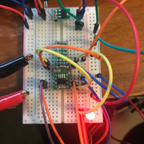
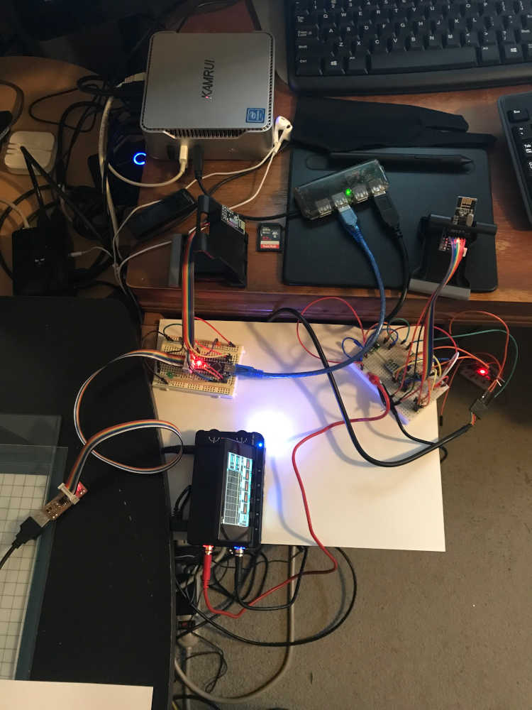
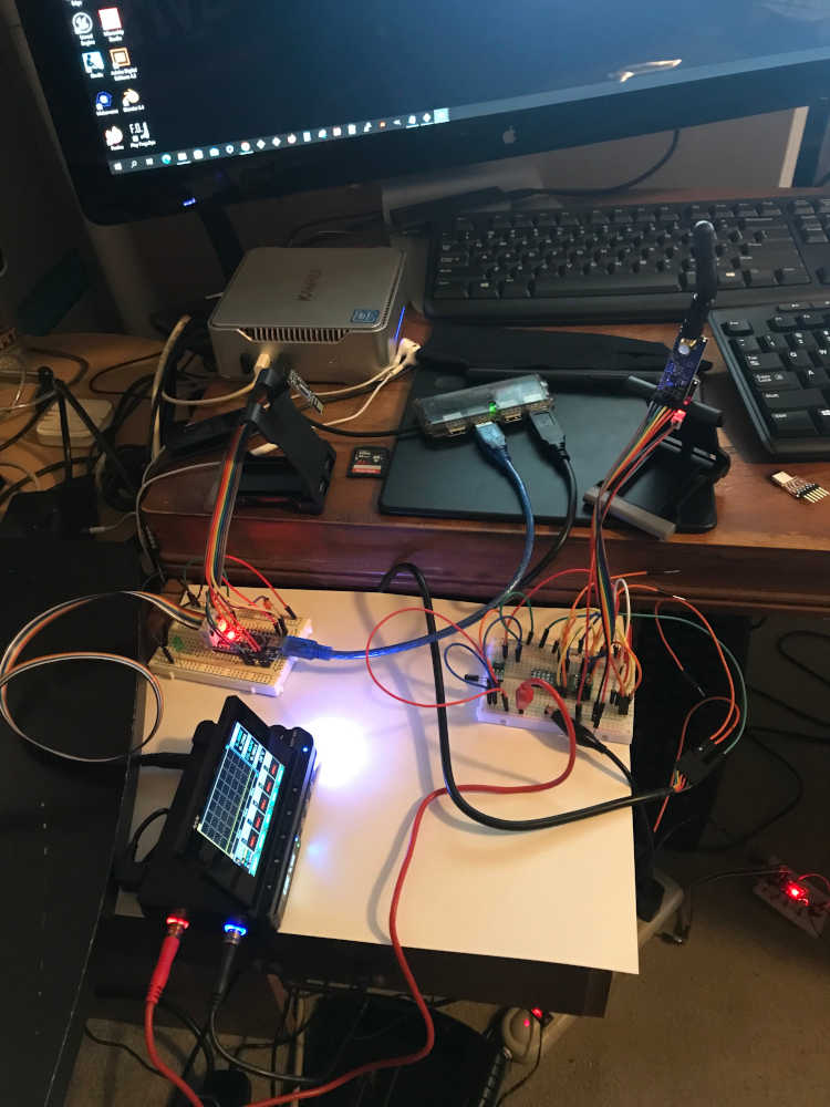
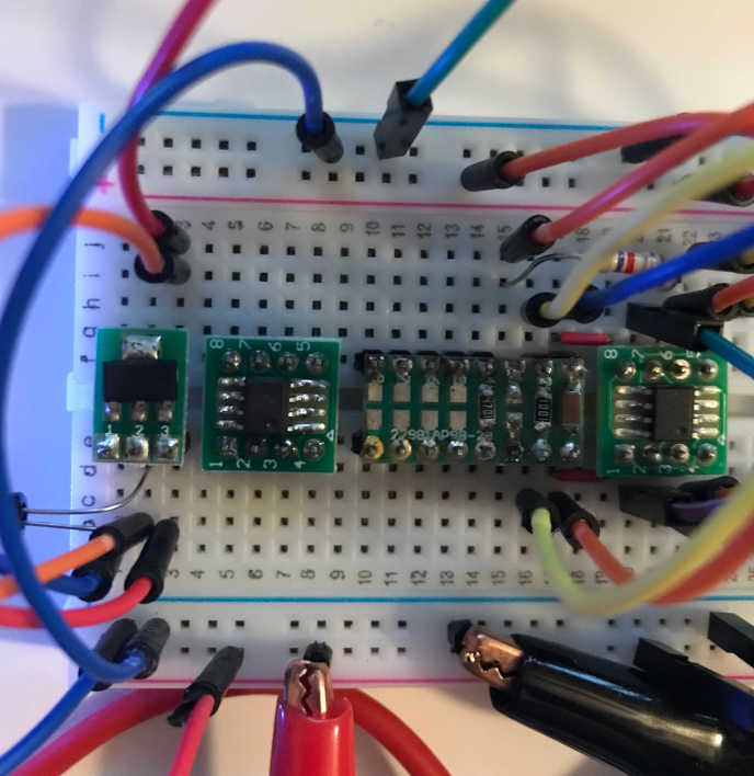
I wanted to explore the ATtiny412 since it is the mcu I have in abundance. Using a protoboard for mobility, I soldered the t412 on and added pins compatible with a breadboard. I knew I needed a 3.3v power supply, so I soldered the regulator on a protoboard and added pins compatible with a breadboard. I placed the protoboards on a breadboard and wired the system using Neil’s as a guide.
ATtiny412 development board in modules:
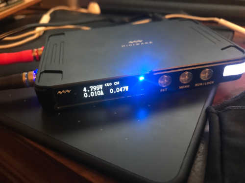
- Powerup! I have the MPD-P905 Miniware digital power supply as well as the MDP-M01 as a display control module. I had a basic understanding of this equipment, but I had to initiate a spiral to deep dive into the better use of this technology. The User Manual did provide some guidance, but some editing is desperately needed. I stood on the shoulders of SDG Electronics with the YouTube they provided. I am also able to power the electronics with a 2200 mAh 6.6V LiFe Battery. This will be handy with a battery bus to supply all loads.
Supply voltage and current to the ATtiny412:
-
I was able to program the t412 and load the hello.t412.blink using updi as the interface. I will have to mount a 1uF capacitor somewhere to filter the power to the t412. I wanted to connect the nrf24l01+ to the t412, but decided to use the arduino nano since I have an abundance already made.
-
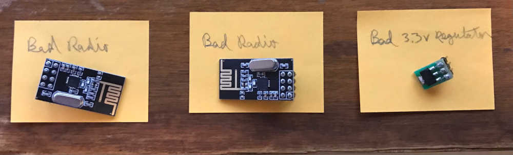
The spiral with the nrf24l01 and nano was tough, but extremely rewarding. I first tried lighting an led with a button, but decided to print hello world instead. My first radios were fried by my power supply; I did see Hello World for just a moment :) I took another spiral with the miniware. I learned a lot, but abandoned using the miniware and just used the 3.3v off of the nano; this allowed me to learn through errors. The good part is that I only fried 2 radios :) I thought I only fried one, so I replaced it first; I did not have success. However, I did replace the second radio; still no success. This was due to the connections being flipped 180 degrees when I plugged them in. Once I realized that, I had success with the Hello World. Thanks to Dejan Nedelkovski on www.HowToMechatronics.com
My notes to wrap my head around using a t412 with a nRF24L01 module:
Casualties in the process:
- The next spiral was using a button on one radio to light a LED on the other radio. Very challenging. There were differences in the code provided on the Arduino Project Hub: [Controls a LED from NRF24L01] (https://projecthub.arduino.cc/MinukaThesathYapa/1425f659-e327-44e4-8c40-c78c62a72e25) but I used what I learned from Dejan Nedelkovski to correct the errors. I was able to blink the LED from across the room. YAY!
-
I had many iterations of programming the nano with an Atmel ICE using the Arduino IDE. I used a separate USB power supply to provide power to the nano while plugging the Atmel ICE into the computer USB port. I learned a great trick from Pert here Sketch > Upload Using Programmer…never knew that. Now my world has changed :)
-
A note about programming the Nano…I was not able to program it directly through the USB port. I used the USBtinyISP as the programmer, but I had to connect it to the old USB Hub to program the Nano. Set programmer to USBtinyISP, then > Sketch > Upload Using Programmer. My workflow was to upload Blink first; once I was able to do that, I tried the other nRF24L01 files successfully.
-
New breakthrough! I was able to setup the tiny412 with the nRF24L01 as a transmitter and receive the transmission on a Nano with the nRF24L01 as a receiver. Using the SimpleRx.ino and SimpleTx.ino that I found here Thank you, Robin2! Using Arduino IDE 1.8.19, I programmed the tiny412 using UPDI three wire from a breadboard with the tiny412 on a prototyping board via the USB to TTL Serial Cable (Don’t forget to check that tx/rx are correct). I used the miniware power supply to power it. The Nano was programmed through the USBtinyISP via an old USB hub. After flashing, I connected the Nano to the old USB hub for power and serial monitor and it worked fine. Then I connected the Nano directly to the computer USB port, change the port to COM4 and it worked fine as well.
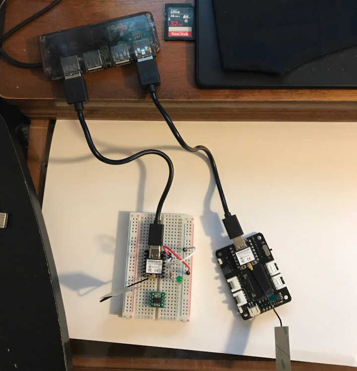
This is the wireless network setup between the t412 and the nano using the nRF24L01 modules. I used a breakout board with the t412 for ease of interfacing:
Communications of the nano:
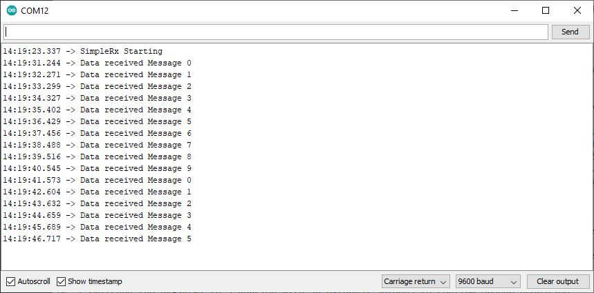
- I wanted to monitor the tiny412 through the serial monitor, but I was not receiving any response. After searching the internet for a solution I found a way to monitor during UPDI Serial Programming. I disconnected UPDI and connected the same TTL Serial connections (TX,RX) to the TX,RX on the tiny412; it worked immediately.
Communications of the t412:

- I switched the nRF24L01 to a version with an external antenna to confirm proper operation.
- Added the LM75 to the breadboard for prototyping. Once I did that, the t412 was no longer able to transmit via the nRF24L01; too much for the little guy to handle. I wired it up using the guidance of Elliot Williams, but I will have to go back through AVR Programming to relearn the process of interfacing the LM75 and flashing the t412 through the programmer. I suspect it will not be able to perform both functions at the same time due to the limited number of communication ports. Don’t forget to look through the AVRProgrammingNotes.txt :)
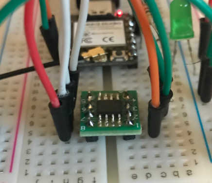
LM75 temperature sensor on a protoboard with the t412 (I removed the wires so you could see it better:)
- Given that the t412 could not handle the LM75 and the nRF24L01 together, I decided to go down another path using the Seeed Studio XIAO ESP32-C3 board as a platform to communicate. I had some failures and successes that need to be recorded here. Although I understand the need to fabricate boards and become proficient at this process, I prefer prototyping before fabricating so my failures are not so costly, i.e. make a board that is doomed to fail in communications. My ultimate goal is to have a board with the LM75 broadcasting the temperature of the its environment to another board connected wirelessly. To begin with the simple step, I connected the LED to one XIAO ESP32-C3 on a breadboard and used the button on the Seeeduino XIAO Expansion Board with a ESP32-C3 installed.
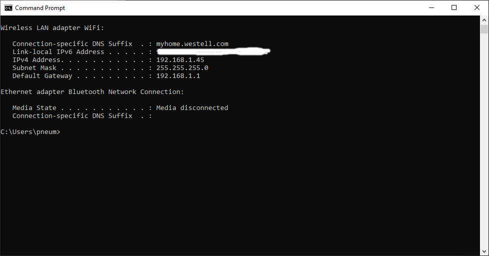
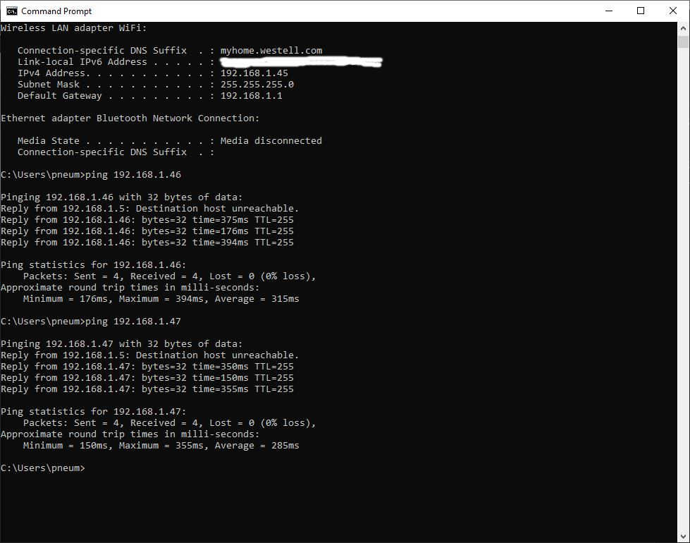
- My thought was to connect the two ESP32-C2 boards wirelessly through a wireless router. I happen to have a DSL router that is no longer in use, so I used what I had :) This spiral had a lot packed into it, so let me unpack it for you. First, I had to reset the router and get access to it. I searched the Internet and found help for the Westell Reset here. Then I connected directly to the router through an ethernet connection and manually set my IP address to the same block as the router…I was in there! I removed the password for ease of access during prototyping and made the SSID something easy: westell. I made sure I could connect with my computer through the wireless connection, then I tried with my phone; all went well!
Now I must program the XIAOs to connect to the router and talk to each other; this is where things got tough, but I had some help. I had a lot of help from the wiki at Seeed Studio on using WiFi on the ESP32-C3. I followed the tutorial and connected both boards to the router:
#include <WiFi.h>

const char* ssid     = "westell";
const char* password = "";

void setup()
{
    Serial.begin(115200);
    delay(10);

    // We start by connecting to a WiFi network

    Serial.println();
    Serial.println();
    Serial.print("Connecting to ");
    Serial.println(ssid);

    WiFi.begin(ssid, password);

    while (WiFi.status() != WL_CONNECTED) {
        delay(500);
        Serial.print(".");
    }

    Serial.println("");
    Serial.println("WiFi connected");
    Serial.println("IP address: ");
    Serial.println(WiFi.localIP());
}
void loop()
{
  }
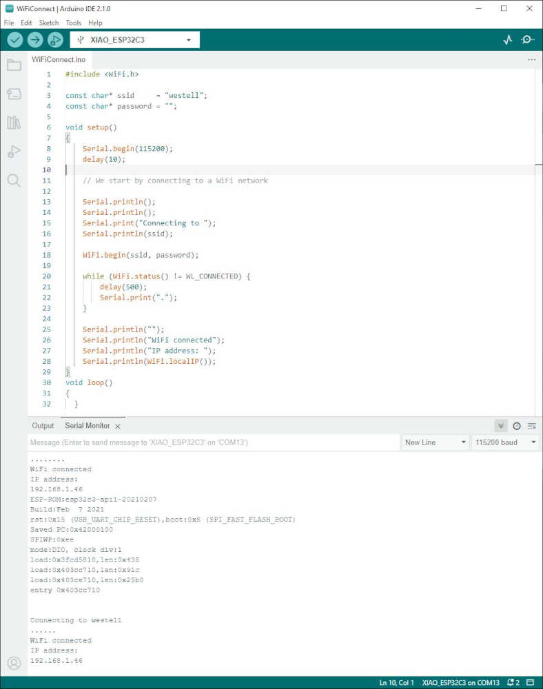
Once I had both connected I pinged them from my computer; all went well.
Seeed Studio didn’t take me beyond connecting so I had to research further. I searched for and found a way to connect two ESP32 boards. There was a good explanation and code to start with. I discovered ezButton as a library in Arduino to make button use easier. This is the code I began with, but I had issues, so don’t use it as is without fully understanding what I went through:
/*
 * This ESP32 code is created by esp32io.com
 *
 * This ESP32 code is released in the public domain
 *
 * For more detail (instruction and wiring diagram), visit https://esp32io.com/tutorials/communication-between-two-esp32
 */

// ESP32 #1: TCP CLIENT + A BUTTON/SWITCH
#include <ezButton.h>
#include <SPI.h>
#include <Ethernet.h>

#define BUTTON_PIN  7
#define SERVER_PORT  4080

ezButton button(BUTTON_PIN);  // create ezButton that attach to pin 7;

byte mac[] = {0x00, 0xAA, 0xBB, 0xCC, 0xDE, 0x03};
IPAddress serverAddress(192, 168, 0, 180);
EthernetClient TCPclient;

void setup() {
  Serial.begin(9600);
  button.setDebounceTime(50); // set debounce time to 50 milliseconds

  Serial.println("ESP32 #1: TCP CLIENT + A BUTTON/SWITCH");

  // Initialize Ethernet Shield:
  if (Ethernet.begin(mac) == 0)
    Serial.println("ESP32 #1: Failed to configure Ethernet using DHCP");

  // connect to TCP server (ESP32 #2 )
  if (TCPclient.connect(serverAddress, SERVER_PORT))
    Serial.println("ESP32 #1: Connected to TCP server");
  else
    Serial.println("ESP32 #1: Failed to connect to TCP server");
}

void loop() {
  button.loop(); // MUST call the loop() function first

  if (!TCPclient.connected()) {
    Serial.println("ESP32 #1: Connection is disconnected");
    TCPclient.stop();

    // reconnect to TCP server (ESP32 #2)
    if (TCPclient.connect(serverAddress, SERVER_PORT))
      Serial.println("ESP32 #1: Reconnected to TCP server");
    else
      Serial.println("ESP32 #1: Failed to reconnect to TCP server");
  }

  if (button.isPressed()) {
    TCPclient.write('1');
    TCPclient.flush();
    Serial.println("ESP32 #1: - The button is pressed,  sent command: 1");
  }

  if (button.isReleased()) {
    TCPclient.write('0');
    TCPclient.flush();
    Serial.println("ESP32 #1: - The button is released, sent command: 0");
  }
}
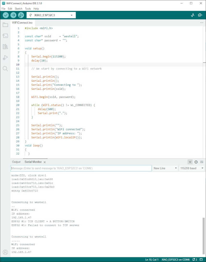
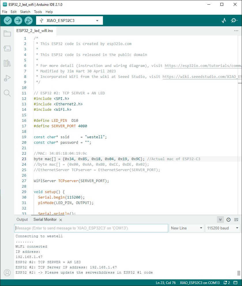
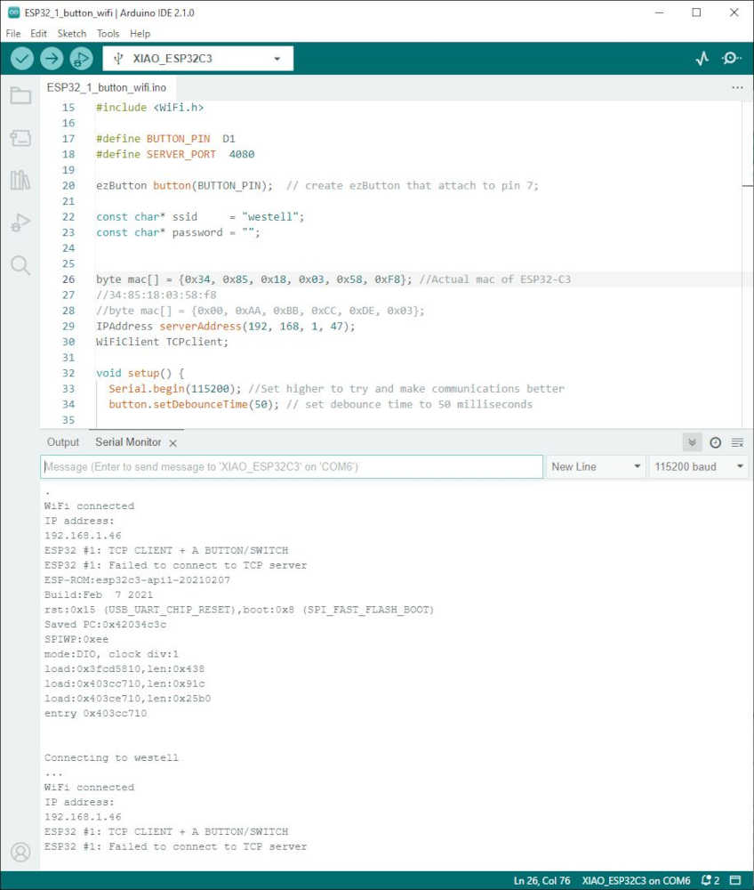
There may be some versioning issues in the Arduino IDE and the libraries used, but by the end of the day, I had it working. This is my version:
/*
 * This ESP32 code is created by esp32io.com
 *
 * This ESP32 code is released in the public domain
 *
 * For more detail (instruction and wiring diagram), visit https://esp32io.com/tutorials/communication-between-two-esp32
 * Modified by Jim Hart 30 April 2023
 * Incorporated WiFi from the wiki at Seeed Studio, visit https://wiki.seeedstudio.com/XIAO_ESP32C3_WiFi_Usage
 */

// ESP32 #1: TCP CLIENT + A BUTTON/SWITCH
#include <ezButton.h>
#include <SPI.h>
#include <Ethernet2.h>
#include <WiFi.h>

#define BUTTON_PIN  D1
#define SERVER_PORT  4080

ezButton button(BUTTON_PIN);  // create ezButton that attach to pin 7;

const char* ssid     = "westell";
const char* password = "";


byte mac[] = {0x34, 0x85, 0x18, 0x03, 0x58, 0xF8}; //Actual mac of ESP32-C3
//34:85:18:03:58:f8
//byte mac[] = {0x00, 0xAA, 0xBB, 0xCC, 0xDE, 0x03};
IPAddress serverAddress(192, 168, 1, 47);
WiFiClient TCPclient;

void setup() {
  Serial.begin(115200); //Set higher to try and make communications better
  button.setDebounceTime(50); // set debounce time to 50 milliseconds

  Serial.println();
  Serial.println();
  Serial.print("Connecting to ");
  Serial.println(ssid);

  WiFi.begin(ssid, password);

  while (WiFi.status() != WL_CONNECTED) {
        delay(500);
        Serial.print(".");
  }
  Serial.println("");
  Serial.println("WiFi connected");
  Serial.println("IP address: ");
  Serial.println(WiFi.localIP());

  Serial.println("ESP32 #1: TCP CLIENT + A BUTTON/SWITCH");

  // Initialize Ethernet Shield: (I didn't use an Ethernet Shield, I used WiFi on the XIAO ESP32-C3)
 // if (Ethernet.begin(mac) == 0)
 //   Serial.println("ESP32 #1: Failed to configure Ethernet using DHCP");

  // connect to TCP server (ESP32 #2 )
  if (TCPclient.connect(serverAddress, SERVER_PORT))
    Serial.println("ESP32 #1: Connected to TCP server");
  else
    Serial.println("ESP32 #1: Failed to connect to TCP server");
}

void loop() {
  button.loop(); // MUST call the loop() function first

  if (!TCPclient.connected()) {
    TCPclient.connect(serverAddress, SERVER_PORT); //Added this line because it was too noisy with connect/disconnect
    //Serial.println("ESP32 #1: Connection is disconnected");
    //TCPclient.stop();

/*
    // reconnect to TCP server (ESP32 #2) (Removed this completely because of noise)
    if (TCPclient.connect(serverAddress, SERVER_PORT))
      Serial.println("ESP32 #1: Reconnected to TCP server");
    else
      Serial.println("ESP32 #1: Failed to reconnect to TCP server");
  */

  }


  if (button.isPressed()) {
    TCPclient.write('1');
    TCPclient.flush();
    Serial.println("ESP32 #1: - The button is pressed,  sent command: 1");
  }

  if (button.isReleased()) {
    TCPclient.write('0');
    TCPclient.flush();
    Serial.println("ESP32 #1: - The button is released, sent command: 0");
  }
}
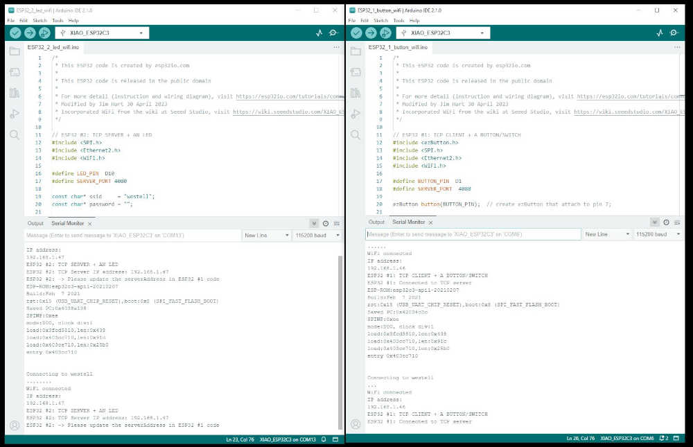
Programmed and connected the LED controlling ESP32-C3 to WiFi:
Programmed and connected the Button bearing ESP32-C3 to WiFi:
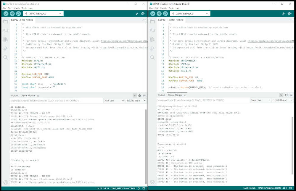
ESP32-C3 XIAOs communicating to each other through the westell router:
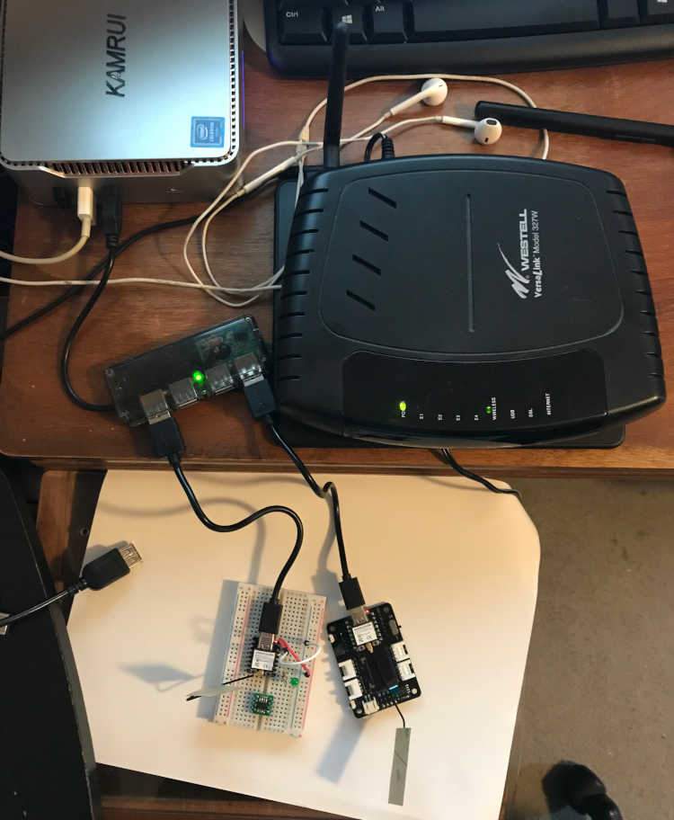
ESP32-C3 XIAOs communicating with each other to light the LED through the westell router after Button presses:
One more step forward…
- Now to add the LM75 to the mix! I placed the LM75 protoboard on the breadboard with the ESP32-C3 that controlled the LED. I wired it up using the guidance of Elliot Williams from AVR Programming using the I2C configuration. LM75 pins 1 and 2, SDA and SCK respectively are connected to the XIAO D4 and D5 respectively. LM75 pin 3 and 4 to GND; pins 5, 6, and 7 (address pins) to GND; pin 8 is VCC (5V in this case). I had pullup resistors on the SDA and SCK as informed by Elliot Williams; turns out they are unnecessary with the XIAO. I studied the LM75 datasheet to learn more and confirm the connections.
At first, I used the BasicUsage Example code provided by Arduino library for I²C Temperature Sensors derived from the LM75. I did not get a response from the mcu other than its name, so I tried another path. I found this ESP32 and LM75 temperature sensor example that provided a small testing program and referred me to another library:
#define VERSION "1.1"

#include <inttypes.h>
#include <Wire.h>

#include <lm75.h>

TempI2C_LM75 termo = TempI2C_LM75(0x48,TempI2C_LM75::nine_bits);

void setup()
{
Serial.begin(9600);
Serial.println("Start");
Serial.print("Actual temp ");
Serial.print(termo.getTemp());
Serial.println(" oC");
delay(2000);
}

void loop()
{
Serial.print(termo.getTemp());
Serial.println(" oC");
delay(5000);
}
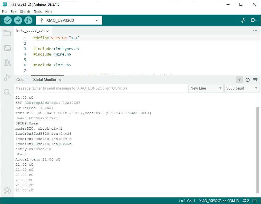
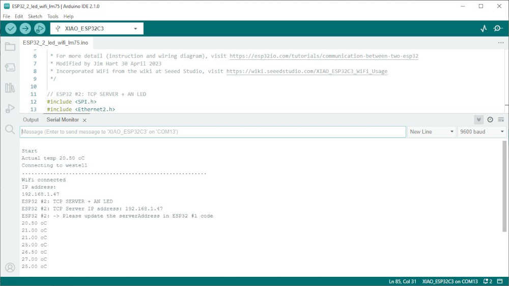
It worked the first time! I was so happy :) I put my finger on the LM75 and watched the temperature rise, then fall when I removed my finger. Test Satisfactory! I saved this file as lm75_esp32_c3.ino.
This is the startup:
- Now I need to transmit this information across a network and have another device receive it. My thoughts are to add it to what I already have working, so let’s give it a try.
I merged the code together and was able to connect to wifi and read the LM75:
- My next step is to send this information to another XIAO ESP32C3 over WiFi.