Interface and Application Programming
This week I will learn about interface and application programming. This will include:
Unit Description
Group assignment:
- Compare as many tool options as possible.
- Document your work on the group work page and reflect on your individual page what you learned.
Individual assignment:
- Write an application that interfaces a user with input and/or output device(s) on a board that you made.
Learning outcomes
- Implement a User Interface (UI) using programming and explore protocols to communicate with an embedded board.
Checklist
Linked to the group assignment page:
-
Linked to the group assignment page:
-
There are two types of assignments, one group and one individual, since I am alone in my personal Fab Lab I will do both. All of my work will be documented here, so there won’t be a group assignment page.
-
Compare as many tool options as possible.
I’ve got to say this week was very thrilling to me. I have never done this before and it was so rewarding to follow the steps provided by the Santos’. I am so thankful for their guidance. There is so much more to learn!
In the video you will see me interacting with the DHT11 sensor to make a visible change. I breathed onto the sensor and covered it with my hand. The temperature is in Celcius and that is the temperature of my personal Fab Lab. The % Humidity was changed by the moisture of my breath :)
Included a ‘hero shot’ of your application running & communicating with your board:
- Included a ‘hero shot’ of your application running & communicating with your board:
I think I could have used some lemons to wipe the grin off my face. I cannot describe how wonderful this felt! Thanks again to the Santos’ at Random Nerd Tutorials!
Included a ‘hero shot’ of your application running & communicating with your board:
- Included a ‘hero shot’ of your application running & communicating with your board:
Tools:
- I had many tools I wanted to explore, but there will not be enough time to look at all of them, so this is a list of tools I used for this assignment:
Devices: Seeed Studio XIAO RP2040, ESP32C3
Editor: Arduino IDE, Thonny (MicroPython)
Languages: C++, Python, Arduino, MicroPython
Device Interfaces: USB Type-C, 802.11n Wireless
- Below you will find the learning process that I like to use by starting simple and then using what I learn to complete the assignment. The ultimate goal is to develop a User Interface that allows interaction with the board I made.
Documented your process:
- Documented your process:
Experience in Learning:
First programming process:
- Device: Seeed Studio XIAO RP2040
- Interfaces: USB Type-C, Boot, Reset, 14 castellated mounting holes, 3-in-one user LED (r,g,b), Power LED, Full-Color RGB LED
- PC Connection:
- Step 1. Press and hold the BOOT button and then connect the Seeed Studio XIAO RP2040 to the PCs USB port.

- Step 2. If the "RPI-RP2" disk is shown on the PC and the Power LED on the Seeed Studio XIAO RP2040 is turned on, the connection is complete.

- Step 3. Press and release Reset button.
- IDE: Arduino 2.3.2 IDE
- Board Manager: “Raspberry Pi Pico/RP2040”
- Selection: Board: “Seeed XIAO RP2040”, Port: COM8 Programming:
-
Copied the Seeed Studio Blink code and saved as SeeedStudio_Blink.ino
-
Upload: Click the Upload button to upload the Blink example code to the board. Compiling…Done Compiling. Uploading…”RPI-RP2” disk is shown on the PC…Flashing E: (RPI-RP2) Wrote 138752 bytes to E:/NEW.UF2…Done Uploading.
- Language: C/C++ (using Arduino IDE)
-
Discovery: digitalWrite(LED_BUILTIN, HIGH) turns off the Red User LED (GPIO Arduino 17); GPIO Arduino 16: Green LED; GPIO Arduino 25: Blue LED. Thank you, Adrian!
-
Digital Interface Example: Connect a pushbutton to Pin D1 and an LED to Pin D0. Uploaded the following code to control the ON/OFF of LED using the pushbutton on the QuenTorres board that I made. Improved interface of the interface :)
//https://wiki.seeedstudio.com/XIAO-RP2040-with-Arduino

const int buttonPin = D1;     // the number of the pushbutton pin
const int ledPin =  D0;      // the number of the LED pin

int buttonState = 0;         // variable for reading the pushbutton status

void setup() {
  // initialize the LED pin as an output:
  pinMode(ledPin, OUTPUT);
  // initialize the pushbutton pin as an input:
  pinMode(buttonPin, INPUT);
}

void loop() {
  // read the state of the pushbutton value:
  buttonState = digitalRead(buttonPin);

  // check if the pushbutton is pressed. If it is, the buttonState is HIGH:
  if (buttonState == HIGH) {
    // turn LED off:
    digitalWrite(ledPin, HIGH);
  } else {
    // turn LED on:
    digitalWrite(ledPin, LOW);
  }
}
In this video, I am using the QuenTorres that I made to mount the XIAO RP2040 and use the onboard components to interact with the microcontroller. I listed the steps above of the whole programming process and then got to press the pushbutton mounted on the QuenTorres board to light the HELLO_LED on the QuenTorres board.
Second programming process:
- Device: Seeed Studio XIAO RP2040
- Interfaces: USB Type-C, Boot, Reset, 14 castellated mounting holes, 3-in-one user LED (r,g,b), Power LED, Full-Color RGB LED
- PC Connection:
- Step 1. Press and hold the BOOT button, while Press and release Reset button with the Seeed Studio XIAO RP2040  connected to the PCs USB port.

- Step 2. If the "RPI-RP2" disk is shown on the PC and the Power LED on the Seeed Studio XIAO RP2040 is turned on, the connection is complete. Continue to Upload below.
- IDE: Arduino 2.3.2 IDE
- Board Manager: “Raspberry Pi Pico/RP2040”
- Selection: Board: “Seeed XIAO RP2040”, Port: COM8 Programming:
-
Copied the Seeed Studio Analog Potentiometer code and saved as SeeedStudio_Potentiometer.ino
-
Upload: Click the Upload button to upload the Blink example code to the board. Compiling…Done Compiling. Uploading…”RPI-RP2” disk is shown on the PC…Flashing E: (RPI-RP2) Wrote 138752 bytes to E:/NEW.UF2…Done Uploading.
-
Language: C/C++ (using Arduino IDE)
-
Analog Interface Example: Connect a potentiometer to Pin A0 and an LED to Pin 0. Then upload the following code to control the blinking interval of the LED by rotating the potentiometer knob.
//https://wiki.seeedstudio.com/XIAO-RP2040-with-Arduino

const int sensorPin = A0;
const int ledPin =  0;
void setup() {
  // declare the ledPin as an OUTPUT:
  pinMode(sensorPin, INPUT);
  pinMode(ledPin, OUTPUT);
}

void loop() {
  // read the value from the sensor:
int sensorValue = analogRead(sensorPin);
  // turn the ledPin on
  digitalWrite(ledPin, HIGH);
  // stop the program for <sensorValue> milliseconds:
  delay(sensorValue);
  // turn the ledPin off:
  digitalWrite(ledPin, LOW);
  // stop the program for for <sensorValue> milliseconds:
  delay(sensorValue);
}
In this video, I am using the FABCAT board (My Final Project :) that I made that has the XIAO RP2040 soldered to it and used an external potentiometer to interact with the microcontroller; this changed the frequncy of the signal sent to the onboad LED. I listed the steps above of the whole programming process and then got to adjust the potentiometer to blink the LED at different frequencies.
Third programming process:
-
Device: Seeed Studio XIAO ESP32C3
-
Interfaces: USB Type-C, Boot, Reset, 14 castellated mounting holes, Power LED, 802.11n Wireless, HTML page served by Web Server
-
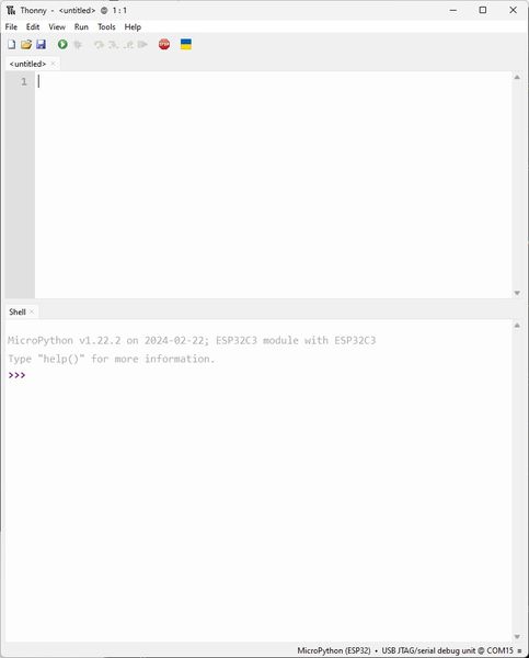
Editor: Thonny (MicroPython)
In order to use the XIAO ESP32-C3 with MicroPython I have learned that I must install MicroPython manually first. I learned this from the Random Nerd Tutorials MicroPython Programming with ESP32 and ESP8266. I have access to the eBook through my courses as a subscriber. Talk about standing on the shoulder of GIANTS! The Santos Technicians from Porto, Portugal have showm me a whole new world of microcontroller programming. I am forever thankful for their guidance. The code you will see is mostly from them and they deserve all the credit!
Flashing MicroPython Software
- Downloading MicroPython Firmware
Flashing MicroPython Firmware using esptool.py
-
Installing esptool.py on your computer
-
Finding the ESP32/ESP8266 Serial Port Name
- Step 1. Connect your board to your computer.

- Step 2. Open the Arduino IDE.

- Step 3. Go to Tools > Port.

- Step 4. Save your ESP32 serial port name (in my case it’s COM15).

- Step 5. Close your Arduino IDE software.
- Place your MicroPython .bin file in the Python accessible directory
ESP32: Flashing MicroPython Firmware
- Erasing Flash Memory
You can see my learning experience below:
Explained any problems you encountered and how you fixed them:
- Explained any problems you encountered and how you fixed them:
Since my ESP32 was different than the tutorial, I had to learn by trial and error to make this work. You can see the errors and the solutions that kept me moving forward.
C:\Users\Jim Hart>esptool.py --chip esp32 --port COM15 erase_flash
'esptool.py' is not recognized as an internal or external command,
operable program or batch file.

C:\Users\Jim Hart>python -m esptool --chip esp32 --port COM15 erase_flash
esptool.py v4.7.0
Serial port COM15
Connecting...

A fatal error occurred: This chip is ESP32-C3 not ESP32. Wrong --chip argument?

C:\Users\Jim Hart>python -m esptool --chip esp32-c3 --port COM15 erase_flash
esptool.py v4.7.0
Serial port COM15
Connecting...
Chip is ESP32-C3 (QFN32) (revision v0.4)
Features: WiFi, BLE, Embedded Flash 4MB (XMC)
Crystal is 40MHz
MAC: 34:85:18:03:58:f8
Uploading stub...
Running stub...
Stub running...
Erasing flash (this may take a while)...
Chip erase completed successfully in 17.6s
Hard resetting via RTS pin...
- Flashing MicroPython Firmware on ESP32 with esptool.py
C:\Users\Jim Hart>python -m esptool --chip esp32-c3 --port COM15 write_flash -z 0x1000 ESP32_GENERIC-20240222-v1.22.2.bi
n
esptool.py v4.7.0
Serial port COM15
Connecting...
Chip is ESP32-C3 (QFN32) (revision v0.4)
Features: WiFi, BLE, Embedded Flash 4MB (XMC)
Crystal is 40MHz
MAC: 34:85:18:03:58:f8
Uploading stub...
Running stub...
Stub running...
Configuring flash size...
Unexpected chip id in image. Expected 5 but value was 0. Is this image for a different chip model?

A fatal error occurred: ESP32_GENERIC-20240222-v1.22.2.bin is not an ESP32-C3 image. Use --force to flash anyway.

C:\Users\Jim Hart>python -m esptool --chip esp32-c3 --port COM15 write_flash -z 0x1000 ESP32_GENERIC_C3-20240222-v1.22.2.bin
esptool.py v4.7.0
Serial port COM15
Connecting...
Chip is ESP32-C3 (QFN32) (revision v0.4)
Features: WiFi, BLE, Embedded Flash 4MB (XMC)
Crystal is 40MHz
MAC: 34:85:18:03:58:f8
Uploading stub...
Running stub...
Stub running...
Configuring flash size...
Flash will be erased from 0x00001000 to 0x00197fff...
Compressed 1664208 bytes to 998338...
Wrote 1664208 bytes (998338 compressed) at 0x00001000 in 13.6 seconds (effective 979.5 kbit/s)...
Hash of data verified.

Leaving...
Hard resetting via RTS pin...
I received errors when I opened the COM15 port in Thonny, so I erased and flashed again using the guidance from the MicroPython Download page.
C:\Users\Jim Hart>python -m esptool --chip esp32c3 --port COM15 erase_flash
esptool.py v4.7.0
Serial port COM15
Connecting...
Chip is ESP32-C3 (QFN32) (revision v0.4)
Features: WiFi, BLE, Embedded Flash 4MB (XMC)
Crystal is 40MHz
MAC: 34:85:18:03:58:f8
Uploading stub...
Running stub...
Stub running...
Erasing flash (this may take a while)...
Chip erase completed successfully in 17.2s
Hard resetting via RTS pin...

C:\Users\Jim Hart>python -m esptool --chip esp32c3 --port /dev/ttyUSB0 --baud 460800 write_flash -z 0x0 ESP32_GENERIC_C3-20240222-v1.22.2.bin
esptool.py v4.7.0
Serial port /dev/ttyUSB0

A fatal error occurred: Could not open /dev/ttyUSB0, the port is busy or doesn't exist.
(could not open port '/dev/ttyUSB0': FileNotFoundError(2, 'The system cannot find the path specified.', None, 3))

Hint: Check if the port is correct and ESP connected


C:\Users\Jim Hart>python -m esptool --chip esp32c3 --port COM15 --baud 460800 write_flash -z 0x0 ESP32_GENERIC_C3-202402
22-v1.22.2.bin
esptool.py v4.7.0
Serial port COM15
Connecting...
Chip is ESP32-C3 (QFN32) (revision v0.4)
Features: WiFi, BLE, Embedded Flash 4MB (XMC)
Crystal is 40MHz
MAC: 34:85:18:03:58:f8
Uploading stub...
Running stub...
Stub running...
Changing baud rate to 460800
Changed.
Configuring flash size...
Flash will be erased from 0x00000000 to 0x00196fff...
Compressed 1664208 bytes to 998338...
Wrote 1664208 bytes (998338 compressed) at 0x00000000 in 13.2 seconds (effective 1009.4 kbit/s)...
Hash of data verified.

Leaving...
Hard resetting via RTS pin...
All is well now!
Programming:
-
Copied the ESP-MicroPython Blink_LED code and saved as main.py to Computer and to MicroPython device.
-
Language: MicroPython (using Thonny IDE)
-
Digital Interface Example: Controlled directly with code and blinked LED on GPIO2 which is the HELLO_LED on the QuenTorres. Got rid of the button :)
# Complete project details at https://RandomNerdTutorials.com

# Jim Hart sent to XIAO ESP32C3 on QuenTorres board without modifications other than this comment 5/5/2024

from machine import Pin
from time import sleep

led = Pin(2, Pin.OUT)

while True:
  led.value(not led.value())
  sleep(0.5)
Now I want to complete the same experiment as I did with the XIAO RP2040 as demonstrated in the video above, but this time on the XIAO ESP32C3. This is the code copied from - Copied the ESP-MicroPython Pushbutton code and saved as main.py to Computer and to MicroPython device.
# Complete project details at https://RandomNerdTutorials.com
# Jim Hart sent to XIAO ESP32C3 on QuenTorres board with below modifications and than this comment 5/5/2024

from machine import Pin
from time import sleep

led = Pin(2, Pin.OUT) # Changed from 5 to 2 for HELLO_LED on QuenTorres
button = Pin(3, Pin.IN) # Changed from 4 to 3 for BUTTON on QuenTorres

while True:
  led.value(button.value())
  sleep(0.1)
Next I want to complete the same experiment as I did with the potentiometer on the XIAO RP2040 as demonstrated in the video above, but this time on the XIAO ESP32C3 and just print the output in the Serial Monitor. This is the code copied from - Copied the ESP-MicroPython Analog_Read_Pot code and saved as main.py to Computer and to MicroPython device.
# Complete project details at https://RandomNerdTutorials.com
# Jim Hart sent to XIAO ESP32C3 on QuenTorres board with below modifications and than this comment 5/5/2024

from machine import Pin, ADC
from time import sleep

pot = ADC(Pin(4))  # Changed from 34 to 4 for UART_TX on QuenTorres
pot.atten(ADC.ATTN_11DB)       #Full range: 3.3v Number Range 0 - 4095

while True:
  pot_value = pot.read()
  print(pot_value)
  sleep(0.1)
Now to duplicate the PWM controlled LED using the Potentiometer on the XIAO RP2040 as demonstrated in the video above, but this time on the XIAO ESP32C3.
- Copied the ESP-MicroPython PWM_Pot code and saved as main.py to Computer and to MicroPython device.
# Complete project details at https://RandomNerdTutorials.com
# Jim Hart sent to XIAO ESP32C3 on QuenTorres board with below modifications and than this comment 5/5/2024

from machine import Pin, PWM, ADC
from time import sleep

frequency = 5000
led = PWM(Pin(2), frequency) # Changed from 5 to 2 for HELLO_LED on QuenTorres
pot = ADC(Pin(4))  # Changed from 34 to 4 for UART_TX on QuenTorres
pot.width(ADC.WIDTH_10BIT)
pot.atten(ADC.ATTN_11DB)

while True:
  pot_value = pot.read()
  print(pot_value)

  if pot_value < 15:
    led.duty(0)
  else:
    led.duty(pot_value)

  sleep(0.1)
Explained any problems you encountered and how you fixed them:
- Explained any problems you encountered and how you fixed them:
When I try this I receive an error:
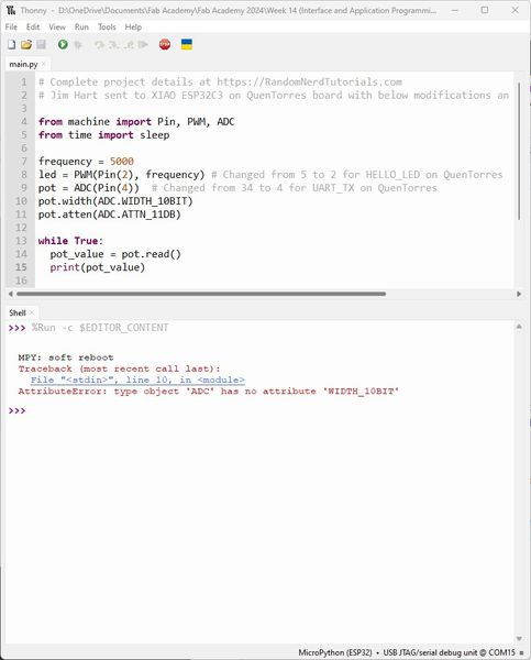
I have a feeling it has to do with using an ESP32C3 rather than an ESP32 for the tutorial. Reading further at the Random Nerd Tutorials I found the answer.
Turns out I needed pot.width(ADC.WIDTH_12BIT). Also, I was limited in travel on the potentiometer to under 1024, so it would crash when I exceeded that. I still need to explore this further to completely understand.
Fourth programming process:
Now it’s time to move to the web server! I had to go through this learning process to be able to use a web interface to interact with the microcontroller. At first it was foreign to me, but every iteration made more sense to me. I still need the help from the Santos Technicians, but at least I recognize what is happening AND I know where to come back to when I need a reminder :) Basically, there is a boot.py that sets up the network and then a main.py that uses the network to communicate between the microcontroller and the user through a web page. It is better explained by the authors, “In our web server examples, we’ll need to write some code on two different files: boot.py and main.py. The boot.py file will contain information that only runs once on boot. This includes importing libraries, network credentials, instantiating pins, connecting to your network, and other configurations. The main.py file will contain the code that runs the web server to serve files and perform tasks based on the requests received from the client.”
- Copied the ESP-MicroPython Web_Server code and saved as boot.py to Computer and to MicroPython device.
This is the boot.py that sets up the network and connects the microcontroller to it through sockets.
# Complete project details at https://RandomNerdTutorials.com
# Jim Hart sent to XIAO ESP32C3 on QuenTorres board without modifications other than this comment 5/5/2024

try:
  import usocket as socket
except:
  import socket

import network

import esp
esp.osdebug(None)

import gc
gc.collect()

ssid = '######'
password = '#######'

station = network.WLAN(network.STA_IF)

station.active(True)
station.connect(ssid, password)

while station.isconnected() == False:
  pass

print('Connection successful')
print(station.ifconfig())
- Copied the ESP-MicroPython Web_Server code and saved as main.py to Computer and to MicroPython device.
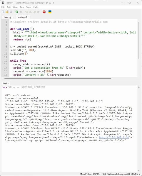
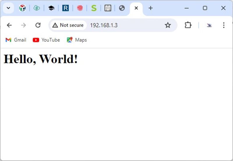
This is the main.py that makes the web page and serves it to any users who connect through a browser via sockets.
# Complete project details at https://RandomNerdTutorials.com
# Jim Hart sent to XIAO ESP32C3 on QuenTorres board without modifications other than this comment 5/5/2024

def web_page():
  html = """<html><head><meta name="viewport" content="width=device-width, initial-scale=1"></head>
  <body><h1>Hello, World!</h1></body></html>"""
  return html

s = socket.socket(socket.AF_INET, socket.SOCK_STREAM)
s.bind(('', 80))
s.listen(5)

while True:
  conn, addr = s.accept()
  print('Got a connection from %s' % str(addr))
  request = conn.recv(1024)
  print('Content = %s' % str(request))
  response = web_page()
  conn.send('HTTP/1.1 200 OK\n')
  conn.send('Content-Type: text/html\n')
  conn.send('Connection: close\n\n')
  conn.sendall(response)
  conn.close()
Once I connected to the local wireless network I was able to watch the events that occurred through the Shell (Similar to a Serial Monitor).
Then I was able to browse the page and received this :)
Explained the UI that you made and how you did it:
- Explained the UI that you made and how you did it:
Now I want to interface with the XIAO ESP32C3 through a web interface and operate the HELLO_LED on the QuenTorres board.
- Copied the ESP-MicroPython Web_Server_Output_Simple code and saved as boot.py to Computer and to MicroPython device.
Included original source code (or a screenshot of the app code if that’s not possible):
- Included original source code (or a screenshot of the app code if that’s not possible):
This is the boot.py that sets up the network and connects the microcontroller to it through sockets. It also establishes the LED that will be controlled through the web interface.
# Complete project details at https://RandomNerdTutorials.com
# Jim Hart sent to XIAO ESP32C3 on QuenTorres board without modifications other than this comment 5/5/2024

try:
  import usocket as socket
except:
  import socket

from machine import Pin
import network

import esp
esp.osdebug(None)

import gc
gc.collect()

ssid = '#####'
password = '#####'

station = network.WLAN(network.STA_IF)

station.active(True)
station.connect(ssid, password)

while station.isconnected() == False:
  pass

print('Connection successful')
print(station.ifconfig())

led = Pin(2, Pin.OUT)
- Copied the ESP-MicroPython Web_Server_Output_Simple code and saved as main.py to Computer and to MicroPython device.
Explained how your application communicates with your embedded board:
- Explained how your application communicates with your embedded board:
This is the main.py that makes the web page and serves it to any users who connect through a browser via sockets. The web page has buttons that the user can click; the click sends a signal to the microcontroller with a 1 or 0 to turn the LED on or off.
# Complete project details at https://RandomNerdTutorials.com
# Jim Hart sent to XIAO ESP32C3 on QuenTorres board without modifications other than this comment 5/5/2024 Although I did change the name of the Web Server after this :)
def web_page():
html = """<html><head><meta name="viewport" content="width=device-width, initial-scale=1"></head>
<body><h1>ESP Web Server</h1><a href=\"?led=on\"><button>ON</button></a>
<a href=\"?led=off\"><button>OFF</button></a></body></html>"""
return html
s = socket.socket(socket.AF_INET, socket.SOCK_STREAM)
s.bind(('', 80))
s.listen(5)
while True:
try:
if gc.mem_free() < 102000:
gc.collect()
conn, addr = s.accept()
conn.settimeout(3.0)
print('Got a connection from %s' % str(addr))
request = conn.recv(1024)
conn.settimeout(None)
request = str(request)
print('Content = %s' % request)
led_on = request.find('/?led=on')
led_off = request.find('/?led=off')
if led_on == 6:
print('LED ON')
led.value(1)
if led_off == 6:
print('LED OFF')
led.value(0)
response = web_page()
conn.send('HTTP/1.1 200 OK\n')
conn.send('Content-Type: text/html\n')
conn.send('Connection: close\n\n')
conn.sendall(response)
conn.close()
except OSError as e:
conn.close()
print('Connection closed')
I think I could have used some lemons to wipe the grin off my face. I cannot describe how wonderful this felt! Thanks again to the Santos’ at Random Nerd Tutorials!
Included a ‘hero shot’ of your application running & communicating with your board:
- Included a ‘hero shot’ of your application running & communicating with your board:
Now I want to interface with the XIAO ESP32C3 through a web interface and sense the environment humidity and temperature through the UART_TX port on the QuenTorres board using a DHT11.
- Copied the ESP-MicroPython Web_Server_DHT code and saved as boot.py to Computer and to MicroPython device.
Included original source code (or a screenshot of the app code if that’s not possible):
- Included original source code (or a screenshot of the app code if that’s not possible):
This is the boot.py that sets up the network and connects the microcontroller to it through sockets. It also establishes the Sensor that will be read and displayed through the web interface.
# Complete project details at https://RandomNerdTutorials.com
# Jim Hart sent to XIAO ESP32C3 on QuenTorres board with modifications below and than this comment 5/5/2024

try:
  import usocket as socket
except:
  import socket

import network
from machine import Pin
import dht

import esp
esp.osdebug(None)

import gc
gc.collect()

ssid = '#####'
password = '#####'

station = network.WLAN(network.STA_IF)

station.active(True)
station.connect(ssid, password)

while station.isconnected() == False:
  pass

print('Connection successful')
print(station.ifconfig())

#sensor = dht.DHT22(Pin(14))
sensor = dht.DHT11(Pin(4)) # Changed the 14 to 4 for the UART_TX port
- Copied the ESP-MicroPython Web_Server_DHT code and saved as main.py to Computer and to MicroPython device.
Explained how your application communicates with your embedded board:
- Explained how your application communicates with your embedded board:
This is the main.py that makes the web page and serves it to any users who connect through a browser via sockets. The web page can be refreshed by the user click to receive any changes in the information. The microcontroller is reading the sensor in a loop and it is displayed locally and to the web page with proper formatting and the vertical progress bars.
# Complete project details at https://RandomNerdTutorials.com
# Jim Hart sent to XIAO ESP32C3 on QuenTorres board without modifications other than this comment 5/5/2024 Although I did change the name of the Web Server :)

def read_sensor():
  global temp, temp_percentage, hum
  temp = temp_percentage = hum = 0
  try:
    sensor.measure()
    temp = sensor.temperature()
    hum = sensor.humidity()
    if (isinstance(temp, float) and isinstance(hum, float)) or (isinstance(temp, int) and isinstance(hum, int)):
      msg = (b'{0:3.1f},{1:3.1f}'.format(temp, hum))

      temp_percentage = (temp+6)/(40+6)*(100)
      # uncomment for Fahrenheit
      #temp = temp * (9/5) + 32.0
      #temp_percentage = (temp-21)/(104-21)*(100)

      hum = round(hum, 2)
      return(msg)
    else:
      return('Invalid sensor readings.')
  except OSError as e:
    return('Failed to read sensor.')

def web_page():
  html = """<html><head><meta name="viewport" content="width=device-width, initial-scale=1">
  <style>body{padding: 20px; margin: auto; width: 50%; text-align: center;}
  .progress{background-color: #F5F5F5;} .progress.vertical{position: relative;
  width: 25%; height: 60%; display: inline-block; margin: 20px;}
  .progress.vertical > .progress-bar{width: 100% !important;position: absolute;bottom: 0;}
  .progress-bar{background: linear-gradient(to top, #f5af19 0%, #f12711 100%);}
  .progress-bar-hum{background: linear-gradient(to top, #9CECFB 0%, #65C7F7 50%, #0052D4 100%);}
  p{position: absolute; font-size: 1.5rem; top: 50%; left: 50%; transform: translate(-50%, -50%); z-index: 5;}</style></head>
  <body><h1>DHT Sensor</h1><h1>XIAO ESP32C3 Web Server</h1><h1>On QuenTorres Board</h1><div class="progress vertical">
  <p>"""+str(temp)+"""*<p>
  <div role="progressbar" style="height: """+str(temp_percentage)+"""%;" class="progress-bar"></div></div><div class="progress vertical">
  <p>"""+str(hum)+"""%</p>
  <div role="progressbar" style="height: """+str(hum)+"""%;" class="progress-bar progress-bar-hum"></div></div></body></html>"""
  return html

s = socket.socket(socket.AF_INET, socket.SOCK_STREAM)
s.bind(('', 80))
s.listen(5)

while True:
  conn, addr = s.accept()
  print('Got a connection from %s' % str(addr))
  request = conn.recv(1024)
  print('Content = %s' % str(request))
  sensor_readings = read_sensor()
  print(sensor_readings)
  response = web_page()
  conn.send('HTTP/1.1 200 OK\n')
  conn.send('Content-Type: text/html\n')
  conn.send('Connection: close\n\n')
  conn.sendall(response)
  conn.close()
I’ve got to say, again, this was a very thrilling week to me. I have never done this before and it was so rewarding to follow the steps provided by the Santos’. I am so thankful for their guidance. There is so much more to learn!
In the video you will see me interacting with the DHT11 sensor to make a visible change. I breathed onto the sensor and covered it with my hand. The temperature is in Celcius and that is the temperature of my personal Fab Lab. The % Humidity was changed by the moisture of my breath :)
Included a ‘hero shot’ of your application running & communicating with your board:
- Included a ‘hero shot’ of your application running & communicating with your board: