Final Project
The problem
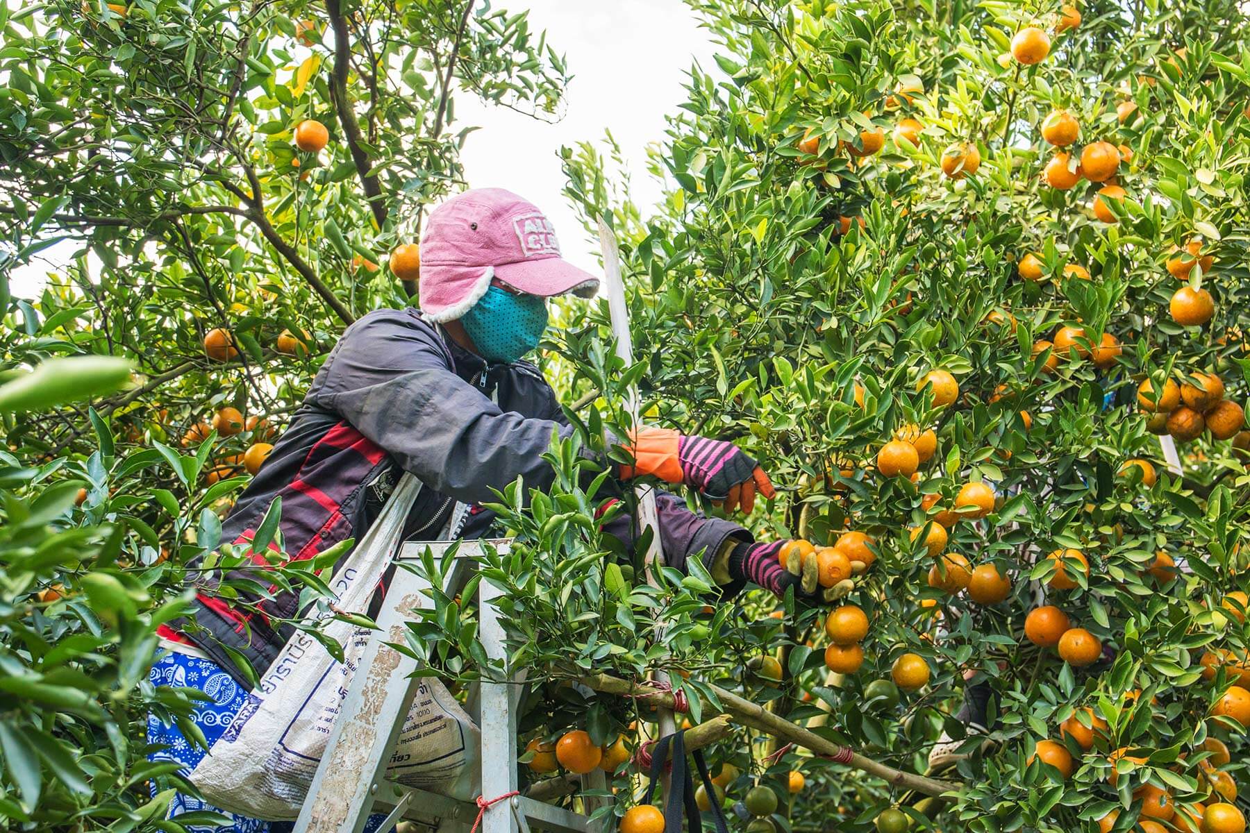
The process of harvesting agricultural products is done by hand. Normally by piece-rate payment based on the volume and amount collected by each worker. This activity reports an estimate of the product and at the end of the process the area is inspected to verify if there are products that have not yet been harvested.
Production is different in each subsector, it means when the land is divided, we are able to identify the areas that have more or less production, considering that, we can begin to improve a process to increase productivity, optimize time, and reduce the loose (because there are lost fruits since workers prefer to collect those that are easier to collect, instead there are subsectors that are not as good as others).
To determine the productivity of the workers, an estimate is made based on the count of lots delivered. When fruits with adequate quality conditions are identified, it is not possible to determine the sector of agricultural land where the fruits were harvested, making impossible for subsequent evaluation of the areas where the harvested product comes from.
The idea
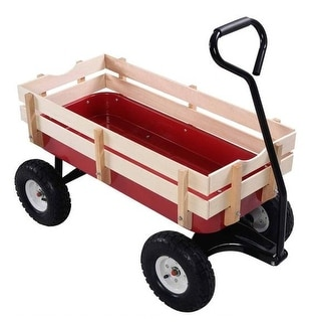
The idea that I am going to develop is the design of a harvesting cart that allows the worker to improve the harvesting process of fruits or vegetables, and that simultaneously allows the harvested product to be related to the specific area from where it was harvested, thus allowing the least productive areas of the soil to be identified for a better treatment. I will use this cart as a reference of my idea.
The cart will also have an integrated scale to keep tracking of the amount of harvested products, this information will allow to know the production in each site so that you can solve some doubts such as:
- Where is the less production?.
- How many products did each worker collect?. (based on the weight)
- How much time is spent collecting on each zone?.
Potential Final Project
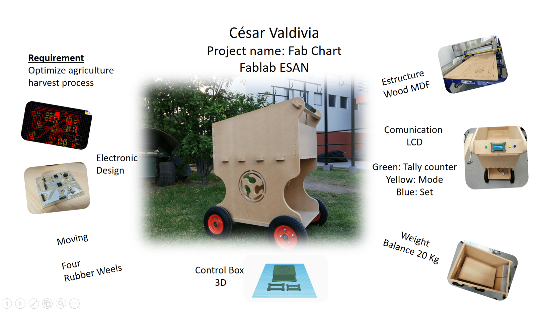
The idea for my final project is to develop a cart for smart harvesting, it will incorporate a scale at the base and allow me to keep track of the total weight of harvested products, it will have an LCD screen that will show that information and also buttons on the handle to carry a count of the harvested points and also other options such as tare the scale according to the container that we decide to use, this information will also be sent via bluetooth to a cellphone to view the information, according to Neil’s advice this project will be a canvas that more later will be possible to work in a more advanced way (changing the bluetooth communication for something with a higher range and uploading the data to the cloud).
What will it do?
The idea for my final project is to develop a cart for smart harvesting, it will incorporate a scale at the base and allow me to keep track of the total weight of harvested products, it will have an LCD screen that will show that information and also buttons on the handle to carry a count of the harvested points and also other options such as tare the scale according to the container that we decide to use, this information will also be sent via bluetooth to a cellphone to view the information, according to Neil’s advice this project will be a canvas that more later will be possible to work in a more advanced way (changing the bluetooth communication for something with a higher range and uploading the data to the cloud).
Who’s done what beforehand?
Well at the beginning I thought that my idea was innovative and nobody had implemented it, but doing a deep search I found this Carry robot and also with a fabacademy project that is being developed this year, it is necessary to specify that both robots stand out for reducing the effort that the person performs when harvesting, in my case I did not consider implementing a displacement system because the product that I plan to harvest will be of reduced weight and size, but I still find very interesting options that could easily be integrated into my project.

What will you design?
I plan to design the cart frame, button handle, PCB board and covers for all the electronics and also for the LCD screen, that would be all hardware related. For the software part I will develop a code to execute all the functions that I plan and I will also elaborate a cellphone app to visualize a GUI.
What materials and components will be used?
For the frame I will use 18mm thick wooden plates, pieces such as the handle and the covers will be printed in ABS plastic (to guarantee certain resistance to weathering), the covers will be cut in acrylic to visualize the contents of the interior and also protect the LCD screen from water splash or rain, for the elaboration of the PCB I will use the milling machine and most of the electronic components available in the fablab.
Where will come from?
All the components come from the local market, this due to the situation we are going through due to COVID-19 and other political factors.
What parts and systems will be made?
In theory, everything will be made using the machines, tools and components of the laboratory except for the tires and electronic components such as the LCD screen and the load cell. In the next point I will detail it more.
What questions need to be answered?
I believe that this project has a lot of potential, I am just laying the foundations so that later on you can work in a more professional way, it is necessary to bear in mind that this is a prototype that will be implemented with the help of digital manufacturing technology. First we must identify the main function of my chart, which is to help us when harvesting by obtaining an exact value of the amount of products harvested according to weight thus obtaining the total yield.
Since Neil stressed the difficulty of the project, said that for the moment we should work with a simple wireless communication means (bluetooth) and not complicate ourselves with the use of a GPS, that is why the main part of the project is to establish the correct weight sensing and also implement a tally counter that will be evidence of the amount of harvested points and by performing a simple mathematical operation we will be able to calculate the yield of that harvested area.
So the 2 questions that should be answered are:
- How to calculate crop productivity?
- How to correctly weight a product? What is the maximum weight?
How will it be evaluated?
What is crop productivity estimation?
Various methods have been developed for quantifying production and productivity of agricultural systems at research plot level and also for agricultural statistics at regional and national level. However, as agricultural production systems are changing to address new challenges, for example, climate smart agricultural practices, the yield estimation methods developed and tested for a particular production system may not adequately reflect the yield for new production systems. For example, the standard crop cut method using sampling frames may create significant bias and error if applied to crops planted in raised beds in row geometry.
Whole plot harvest metod (idea that I plan to apply)
Harvesting the entire field to determine crop yield is normally done in trial plots, excluding one or more boundary lines that may not reflect the tested treatment due to boundary effects. This method can be employed in experimental or demonstration plots. It can also be used to estimate yield from small-scale farmers’ field if farmers are willing to cooperate but is too costly for larger samples of farmers. The complete harvest method is considered the most accurate and often used as a standard for comparing effectiveness and accuracy of other methods. Crops that have a defined maturity date, such as cereals or legumes with a determinate growth habit, can be harvested in a single operation whereas crops with staggered maturity such as banana, cassava and legumes or with an indeterminate growth habit like common bean, cowpea and mungbean require multiple harvests per plot. In many cases, a farmer gathers all his/her produces from his/her land in one place, thresh there and take home after weighing. In such cases, it is easy to estimate the yield by dividing the total yield by the total area that farmers own.
How to correctly weight a product
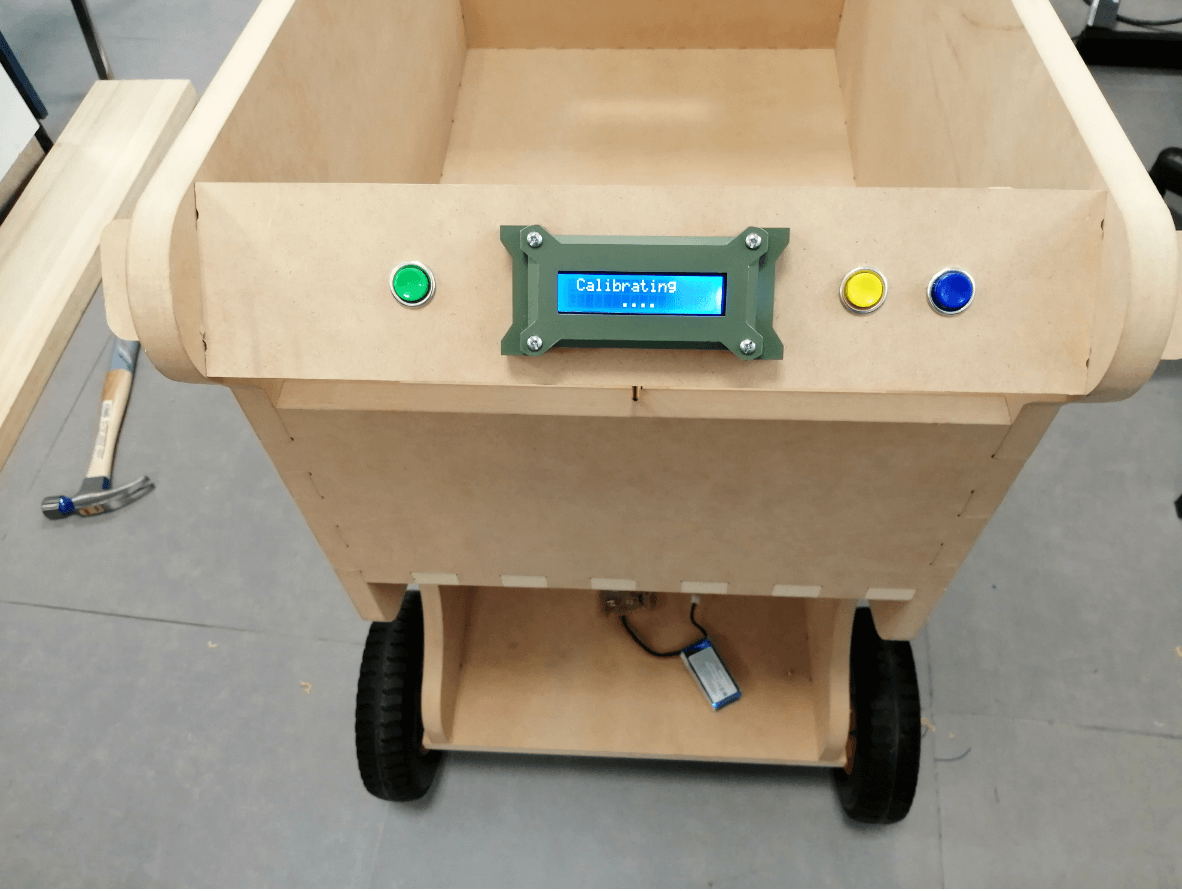
The working principle of this project is easy, before going into details, first, we have to calibrate this system for measuring the correct weight. When the user will power it up the system will automatically start calibrating (depending on the weight of the wooden plank). And if the user wants to calibrate it manually they can press a push button on the handle.
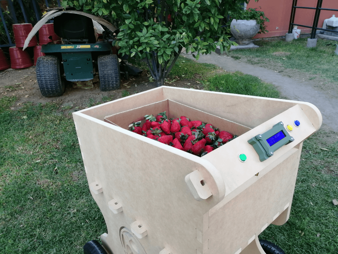
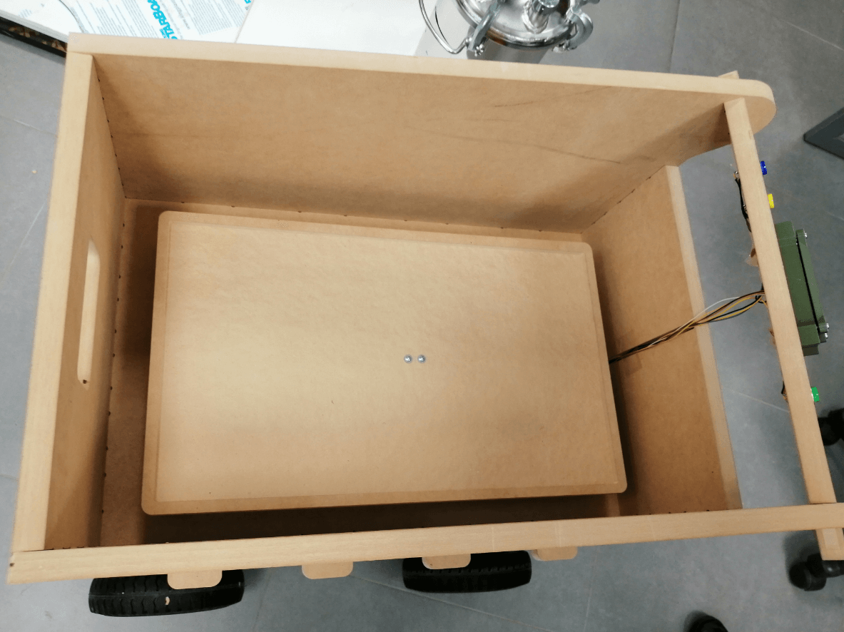
For calibration, wait for LCD indication for putting a plastic tray over the load cell(located at the base of the chart) and wait. After some seconds the calibration process will be finished. After calibration user may put any weight under 20kg (due to the use we estimate for berries) over the load cell and can get the value over LCD in kilograms.
License to protect intellectual properties of my project
Due to the academic nature of my project, I decided on Creative commons. Creative Commons licenses give everyone from individual creators to large institutions a standardized way to grant the public permission to use their creative work under copyright law. From the reuser’s perspective, the presence of a Creative Commons license on a copyrighted work answers the question, “What can I do with this work?”
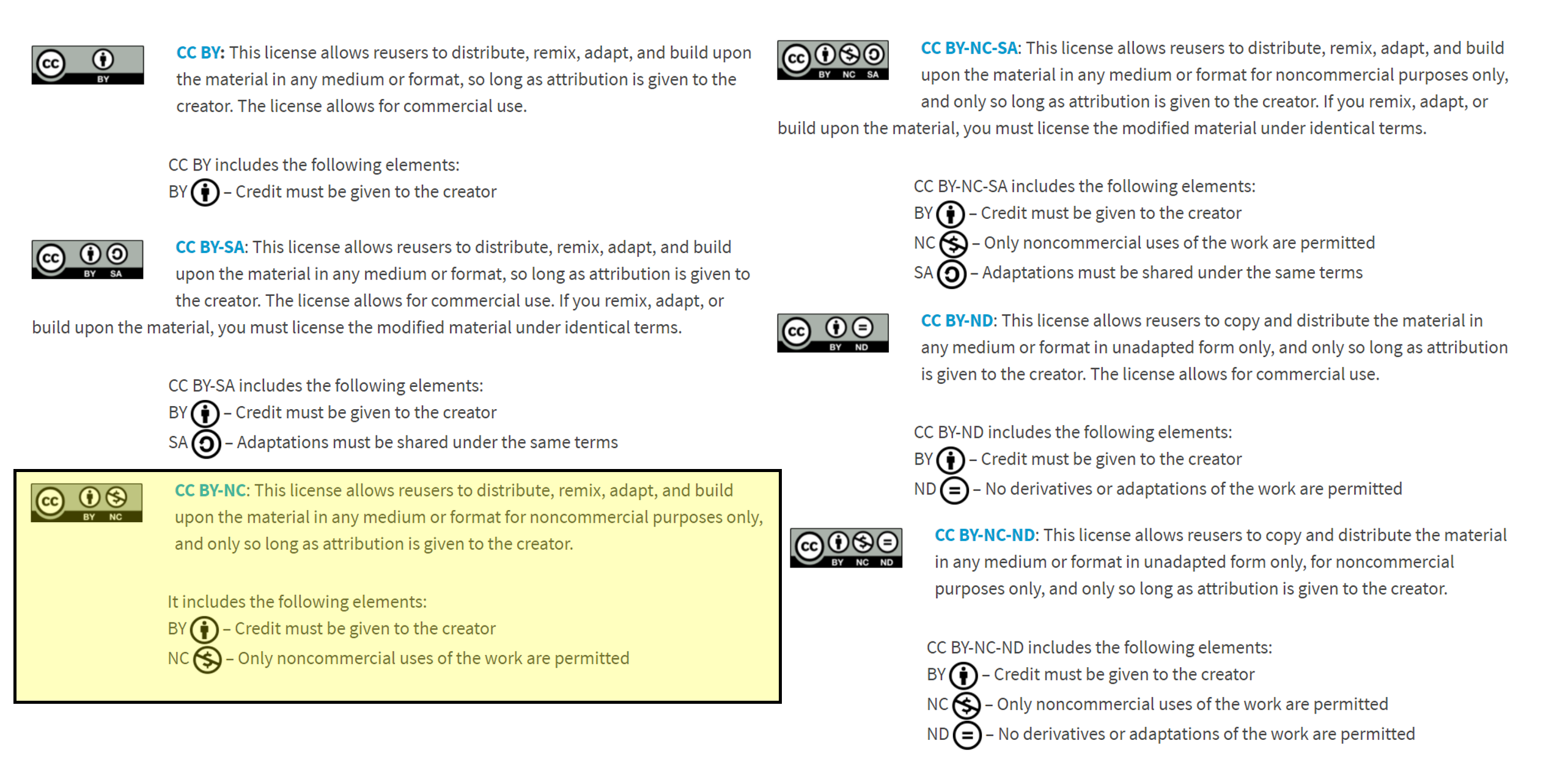
I decided on CC BY-NC, because this license allows reusers to distribute, remix, adapt, and build upon the material in any medium or format for noncommercial purposes only, and only so long as attribution is given to the creator. (seems fair for me) It includes the following elements:
BY – Credit must be given to the creator
NC – Only noncommercial uses of the work are permitted
My implementation plan
Top-down approach
Each system is divided into several subsystems and components. Each of the subsystem is further divided into set of subsystems and components. This process of division facilitates in forming a system hierarchy structure. The complete software system is considered as a single entity and in relation to the characteristics, the system is split into sub-system and component. The same is done with each of the sub-system. This process is continued until the lowest level of the system is reached. The design is started initially by defining the system as a whole and then keeps on adding definitions of the subsystems and components. When all the definitions are combined together, it turns out to be a complete system.
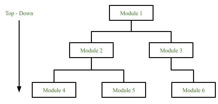
The main advantage of top down approach is that its strong focus on requirements helps to make a design responsive according to its requirements. You can check out my Final project page for more information.
Components
Next I will proceed to detail the necessary components for the elaboration of the cart.
| Process | Task |
|---|---|
| COMPUTER CONTROLLED CUTTING | cut acrylic covers |
| 3D SCANNING AND PRINTING | make a handle with buttons and covers for the electronics and LCD screen |
| ELECTRONICS DESIGN | develop the pcb that will be in charge of controlling our entire project |
| COMPUTER CONTROLLED MACHINING | cut the entire frame for the chart |
| EMBEDDED PROGRAMMING | program the pcb to work properly and run everything planned |
| INPUT DEVICES | interpret load cell values |
| OUTPUT DEVICES | display all necessary information on the LCD screen |
| NETWORKING AND COMMUNICATIONS | establish correctly the bluetooth communication between the chart and the cell phone |
| INTERFACE AND APPLICATION PROGRAMMING | develop the graphical user interface that we will use on the cell phone, to send the information collected by the sensors to a receiving device and display a graph and keep a constant monitoring of the area in which the harvesting is taking place. |
Materials BOM
| Material | Cost (USD) |
|---|---|
| Atmega328au | 3.5$ |
| Smd components (resistors, capacitors, oscillator, etc) | 4$ |
| Bluetooth HC-05 | 5$ |
| LCD display | 5$ |
| Momentary 16mm Push Button Switch DS-212 | 5$ |
| 20kg Load cell | 8$ |
| PCB board | 1$ |
| Wood sheet 18mm | 47$ |
| Wheels | 27$ |
| 1kg of ABS | 18$ |
| Clear acrylic sheet 5mm | 12$ |
| Aluminum rod | 8$ |
| Wood screws | 1$ |
| Bolts and nuts | 1$ |
| Wood glue | 4$ |
| Zip ties | 3$ |
| Wires | 2$ |
| 18650 cell | 8$ |
| 18650 charger | 5$ |
| TOTAL BALANCE | 167.50$ |
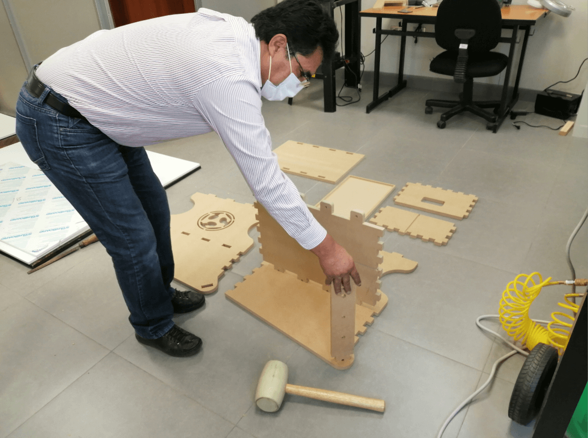
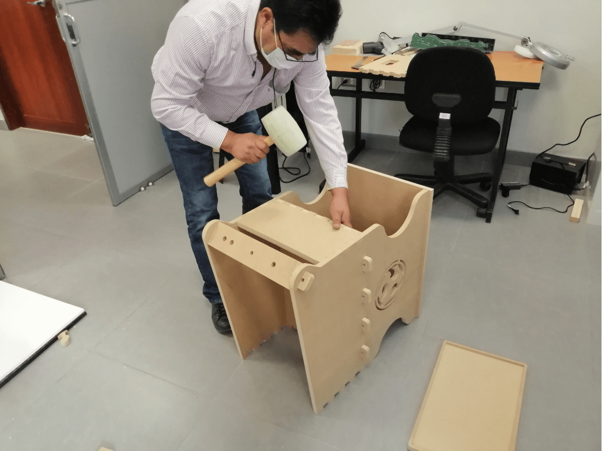
Putting everything together
PCB fabrication
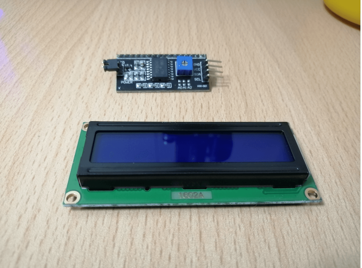
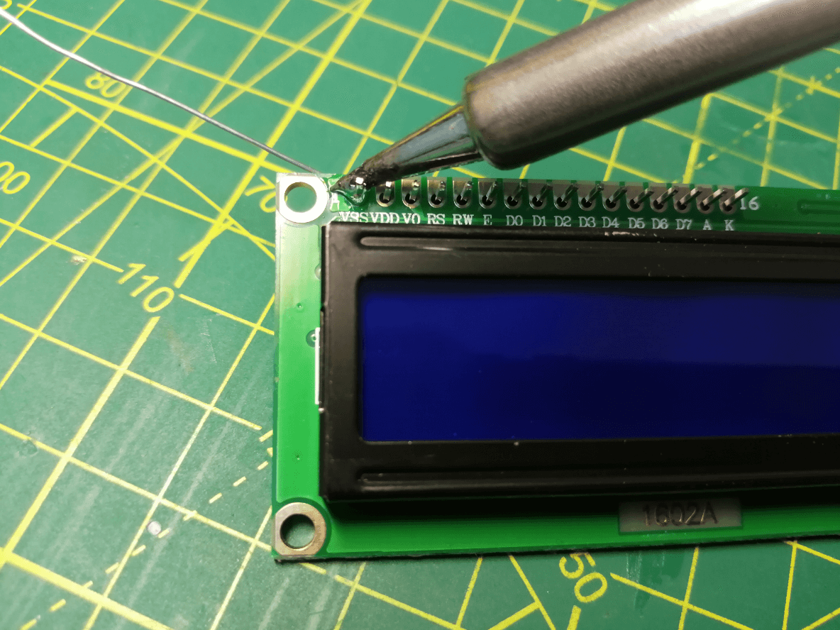
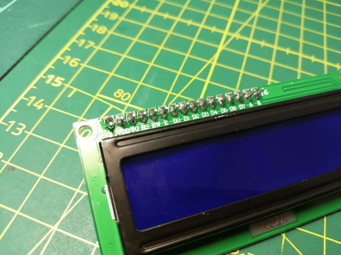
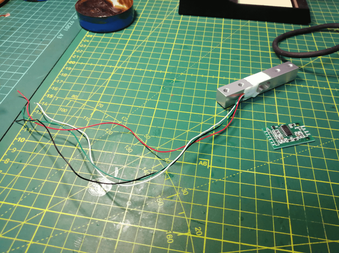
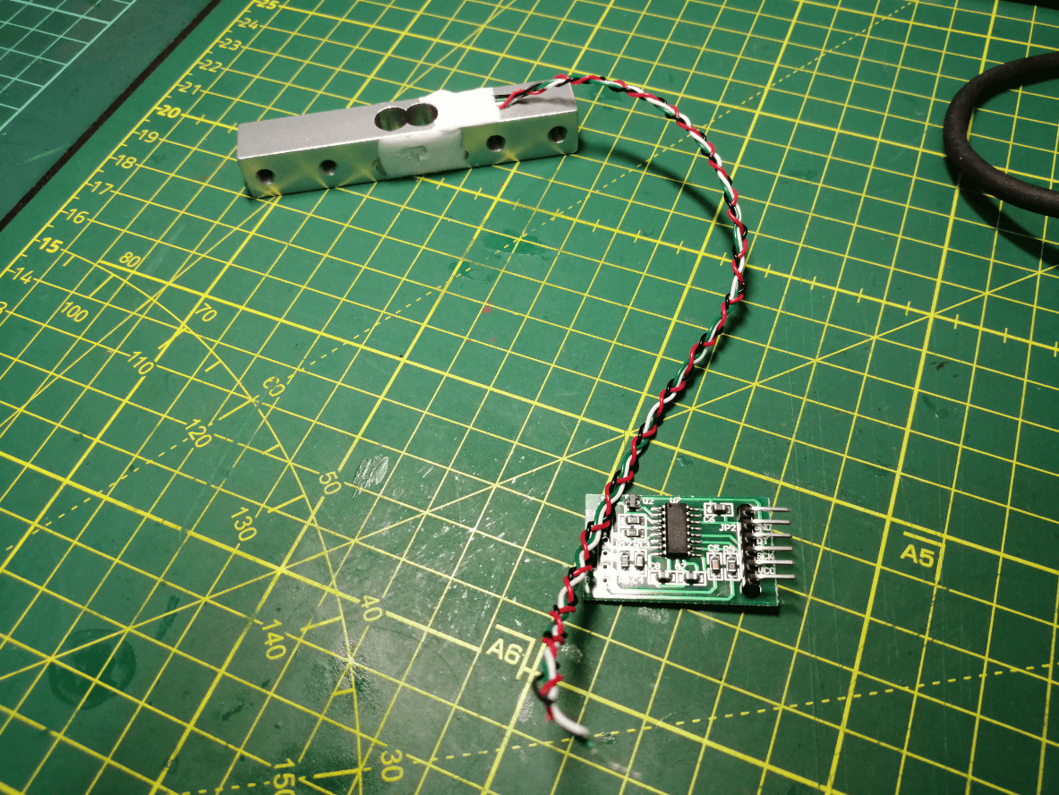
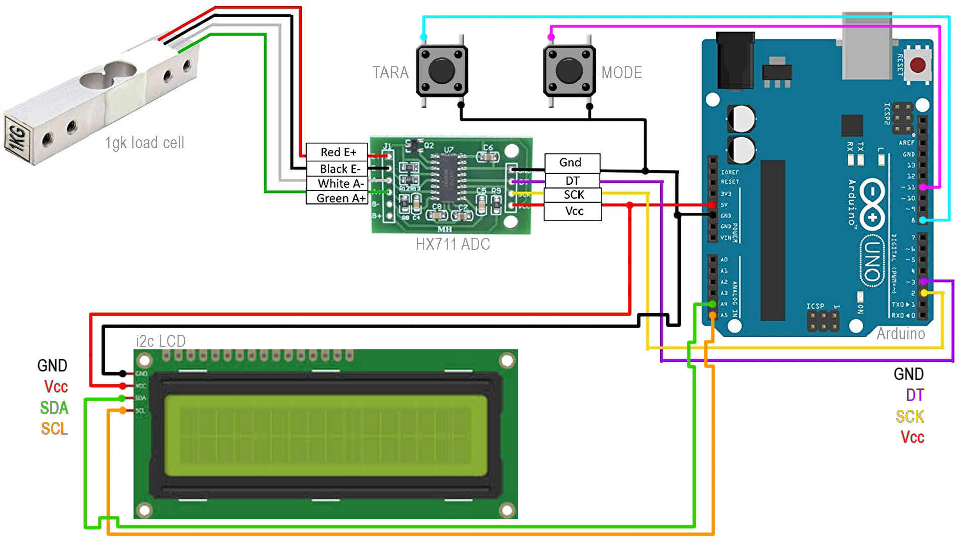
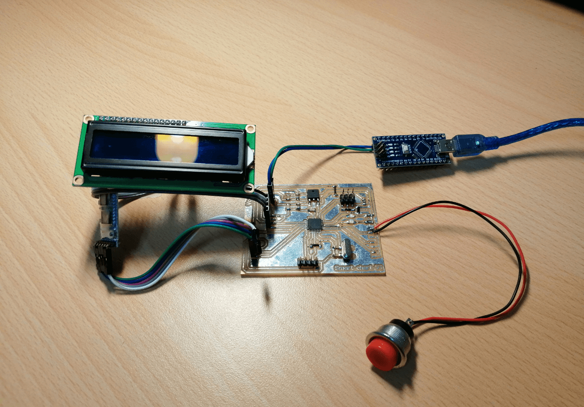
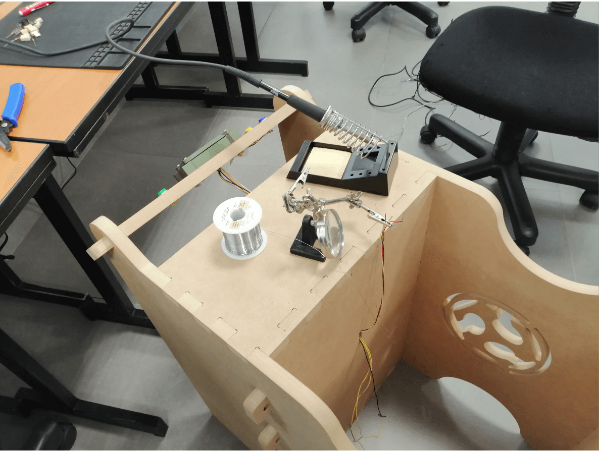
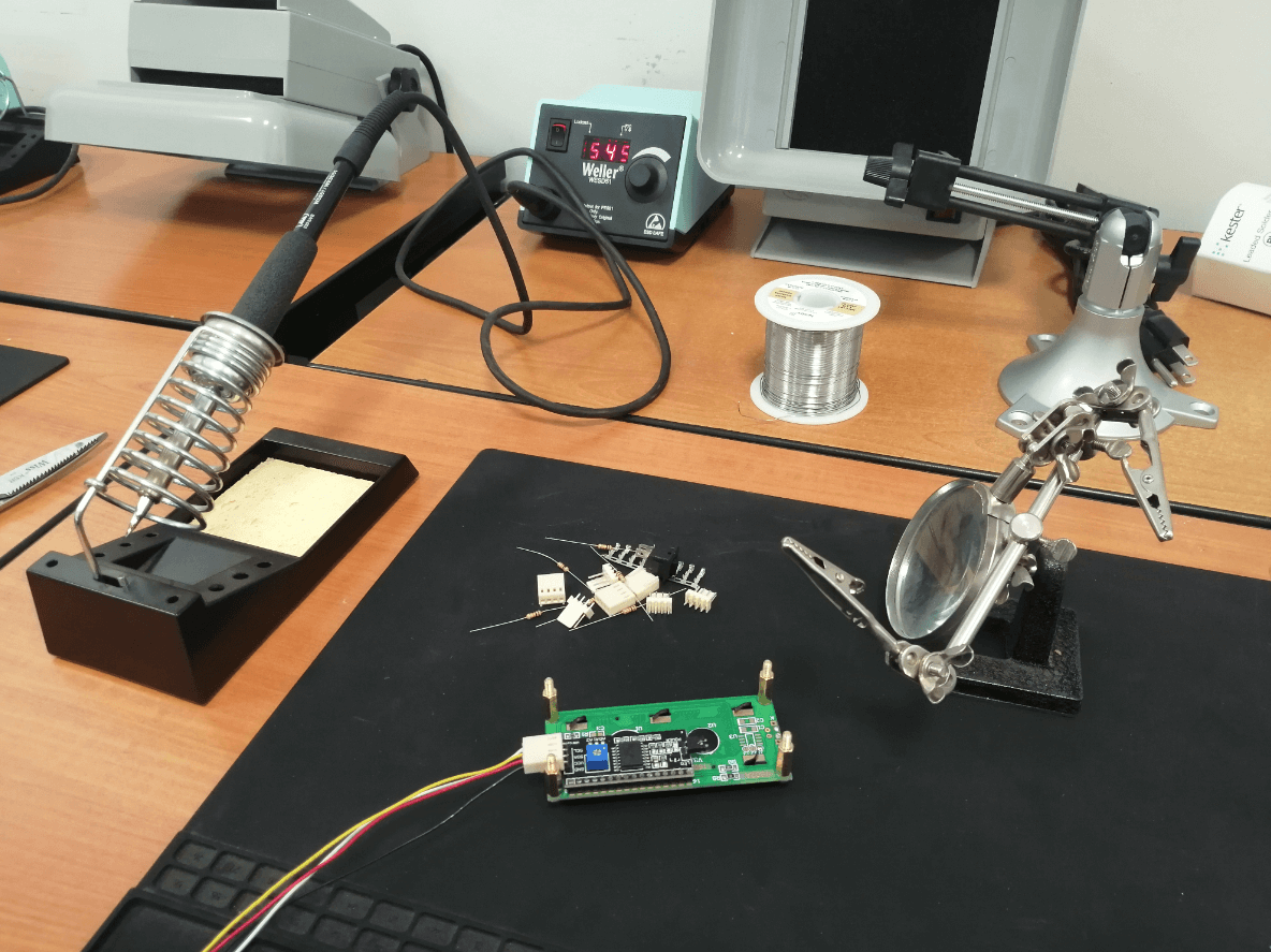
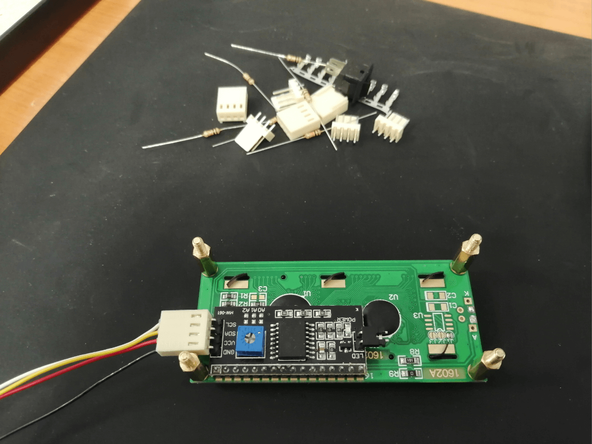
I decided to use a top-down approach, I consider that the most important part (also the most complicated) will be the elaboration of the PCB, so to ensure the correct progress of the final project, I will start by dedicating myself to that part. I decided first to test my idea using an Arduino UNO and connecting the LCD screen and the load cell, we first need to solder our I2C module to the LCD screen and also solder the load cell wires to our 24bit ADC.
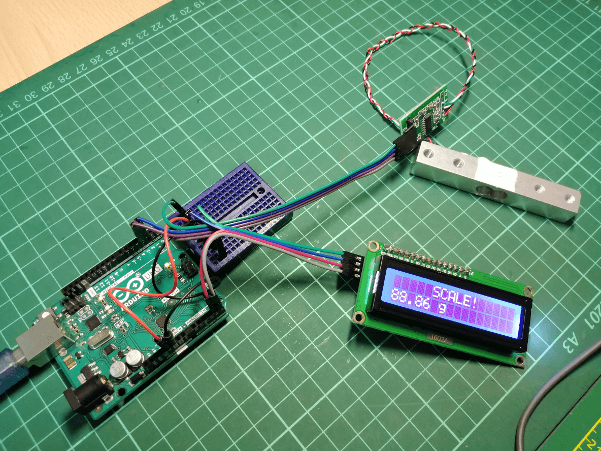
With everything ready for programming, I found an example that was very helpful Electronoobs Strain gauge, I made some modifications to the code and check that everything was working correctly (especially the LCD screen) and perform a simple test without calibrating the load cell, the purpose of this The test was to demonstrate that all the components of my final project worked correctly and also define the pins that I would assign to each one of them.
Now that everything is taking shape, I can proceed to elaborate the PCB, for this I will use EasyEDA to elaborate my one-sided PCB with SMD components and I will use the Atmega328p-au as a microncontroller due to the number of pins it has and the frequency greater than the one that used before (unlike the ATtiny85), first we must locate all the components that we will use in our worksheet and then make the connection of all the parts that we will use.
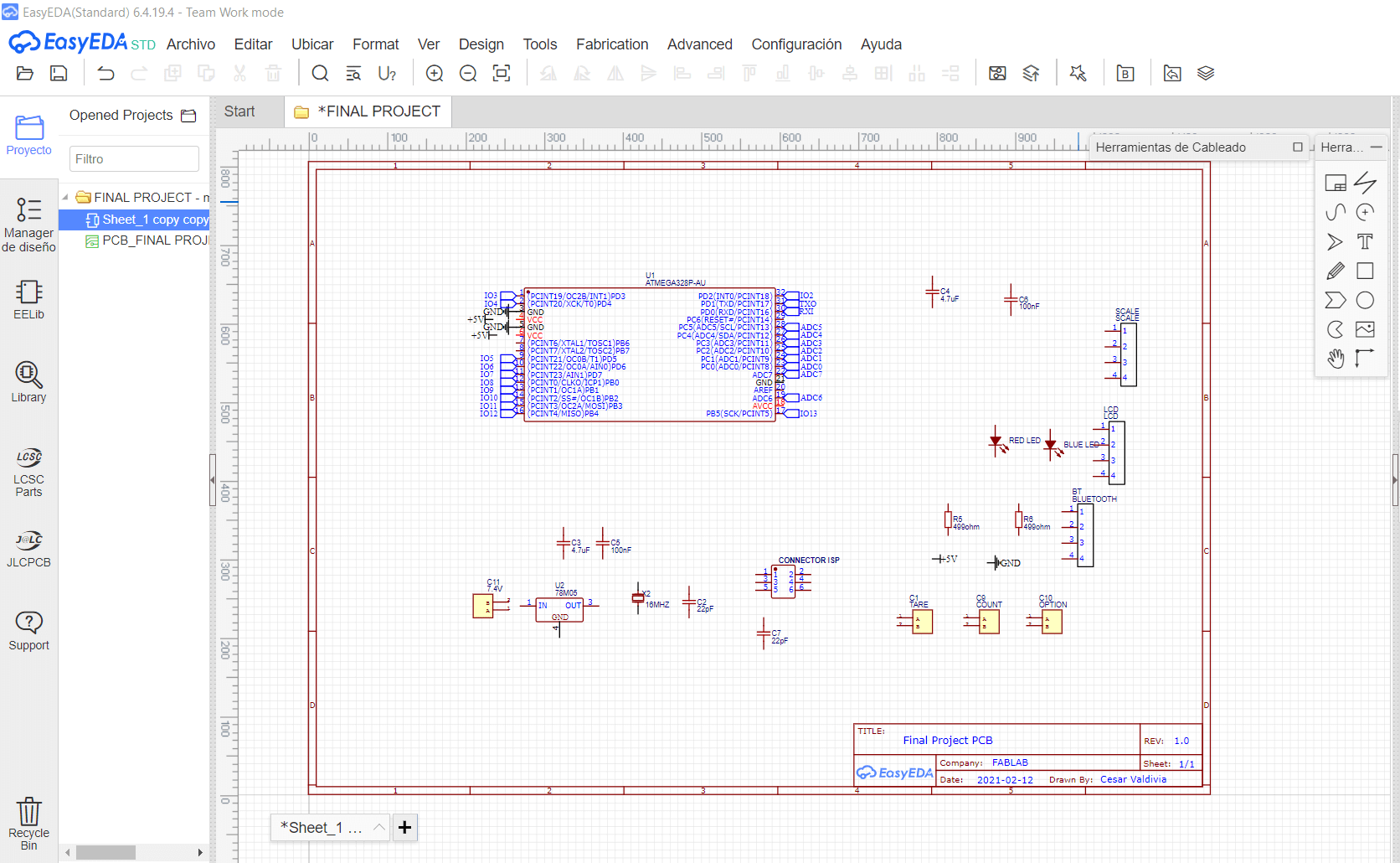
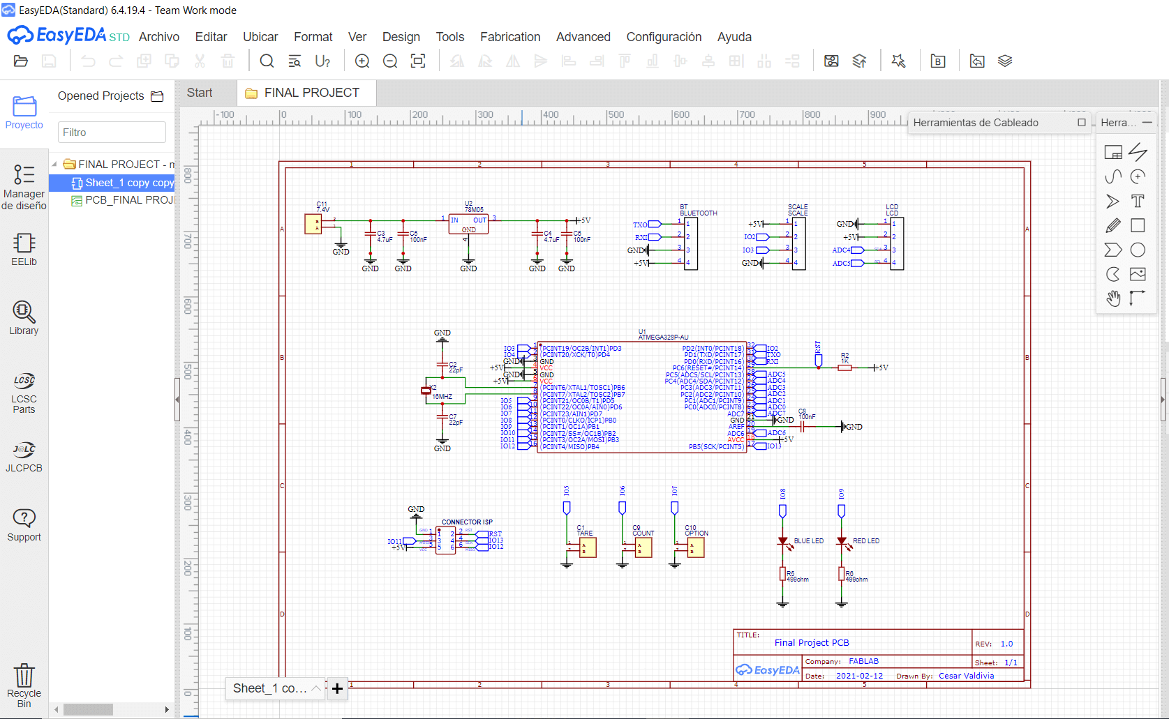
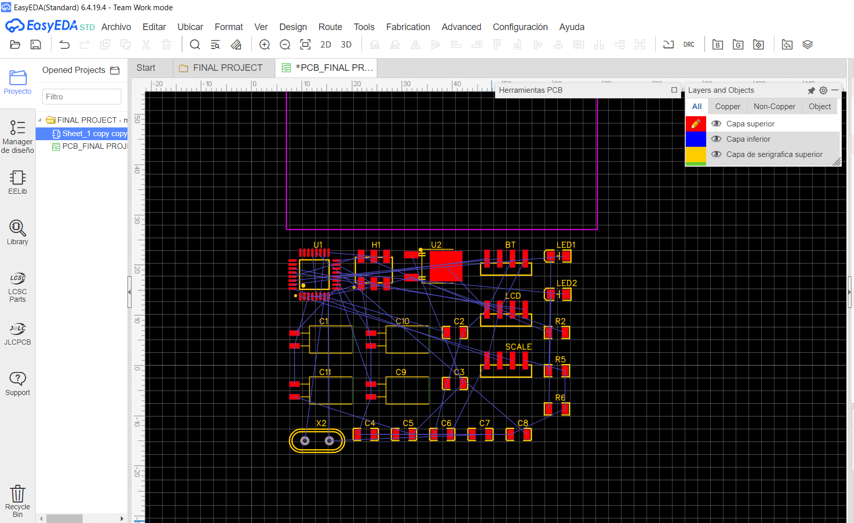
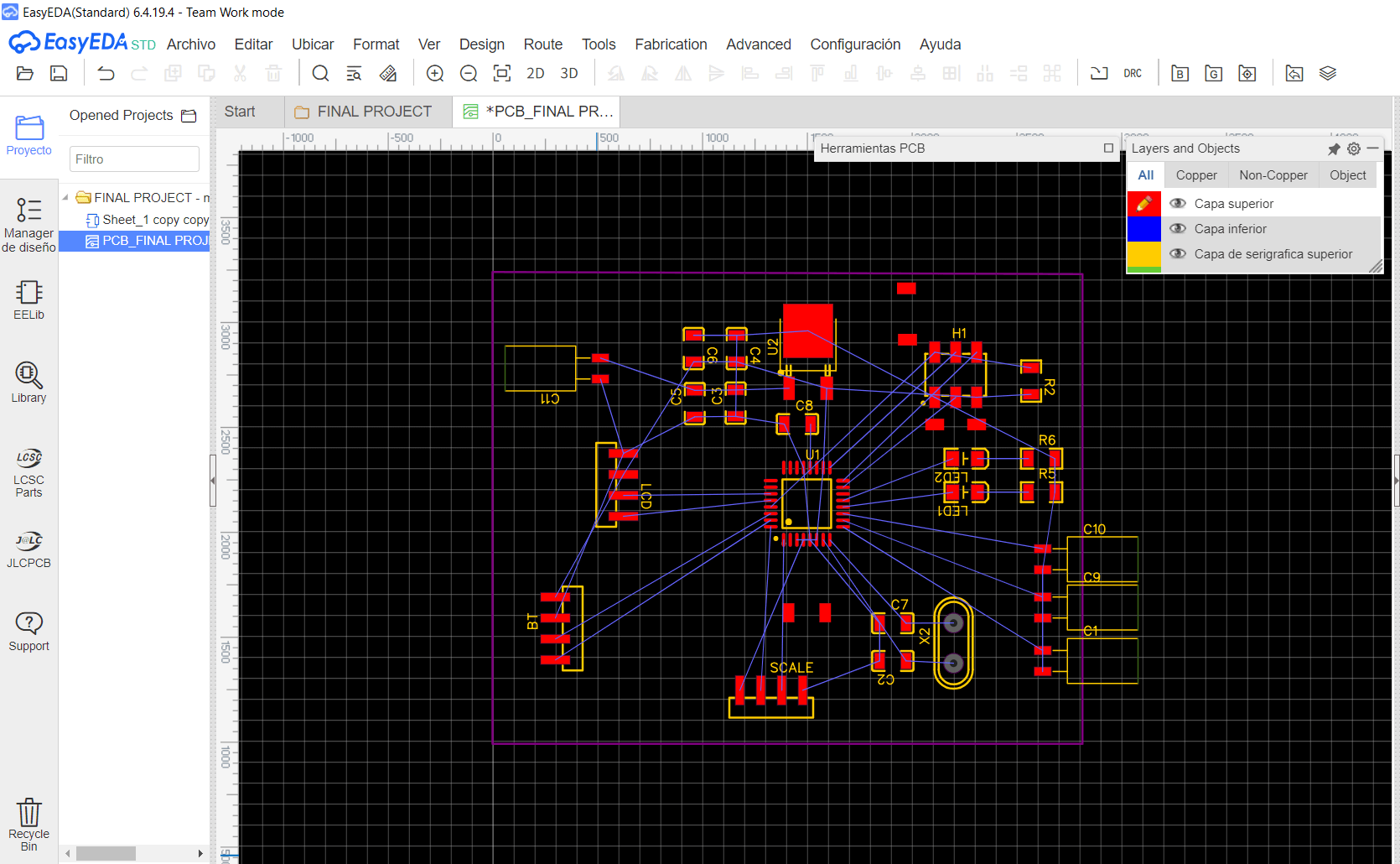
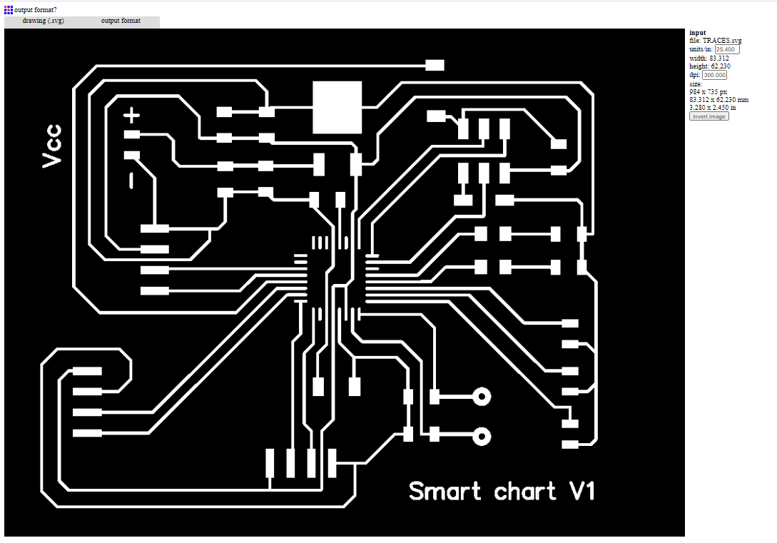
Next we can proceed to elaborate the PCB itself, by default the components will appear located in no specific order, so the first task is to locate them in the purple box known as OUTLINE, with all the components located in the location we consider the best, We can start creating the pads to connect each of the components, we can use the blue lines that indicate the beginning and end of each of the connections, I decided to use a pad thickness of 15mil because I plan to use a endmill of 1/64 or 0.4mm diameter, after all that long process I decided to add a little text to point out some important parts and also to name my board.
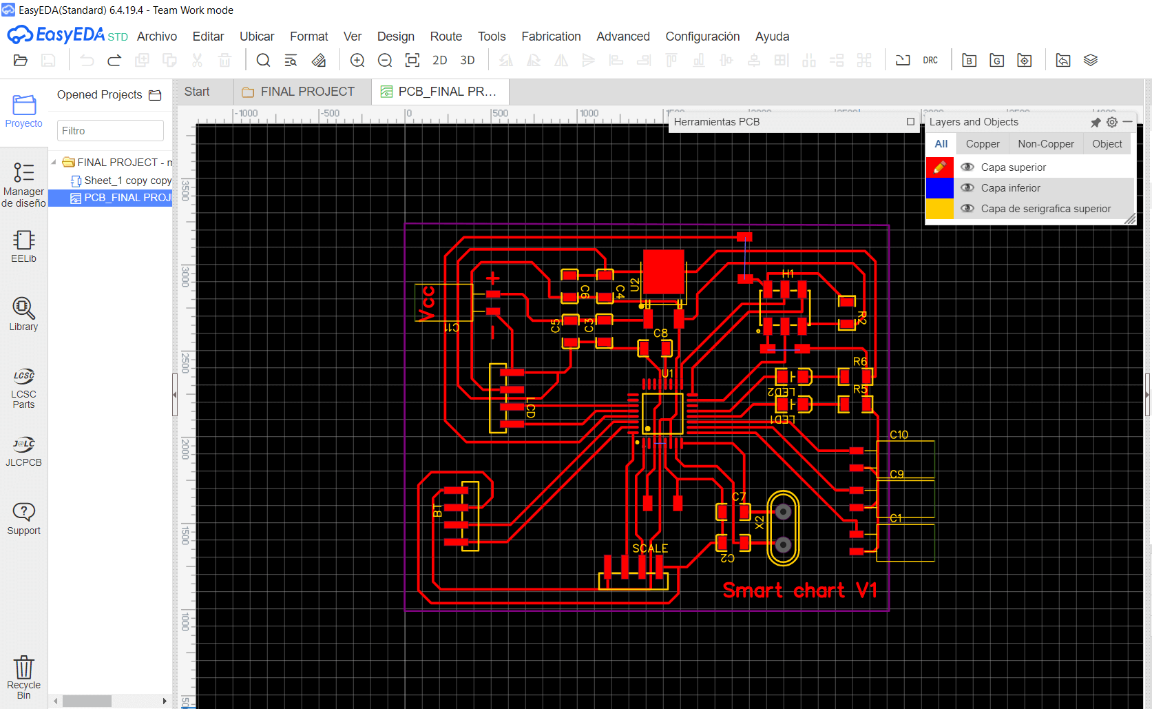
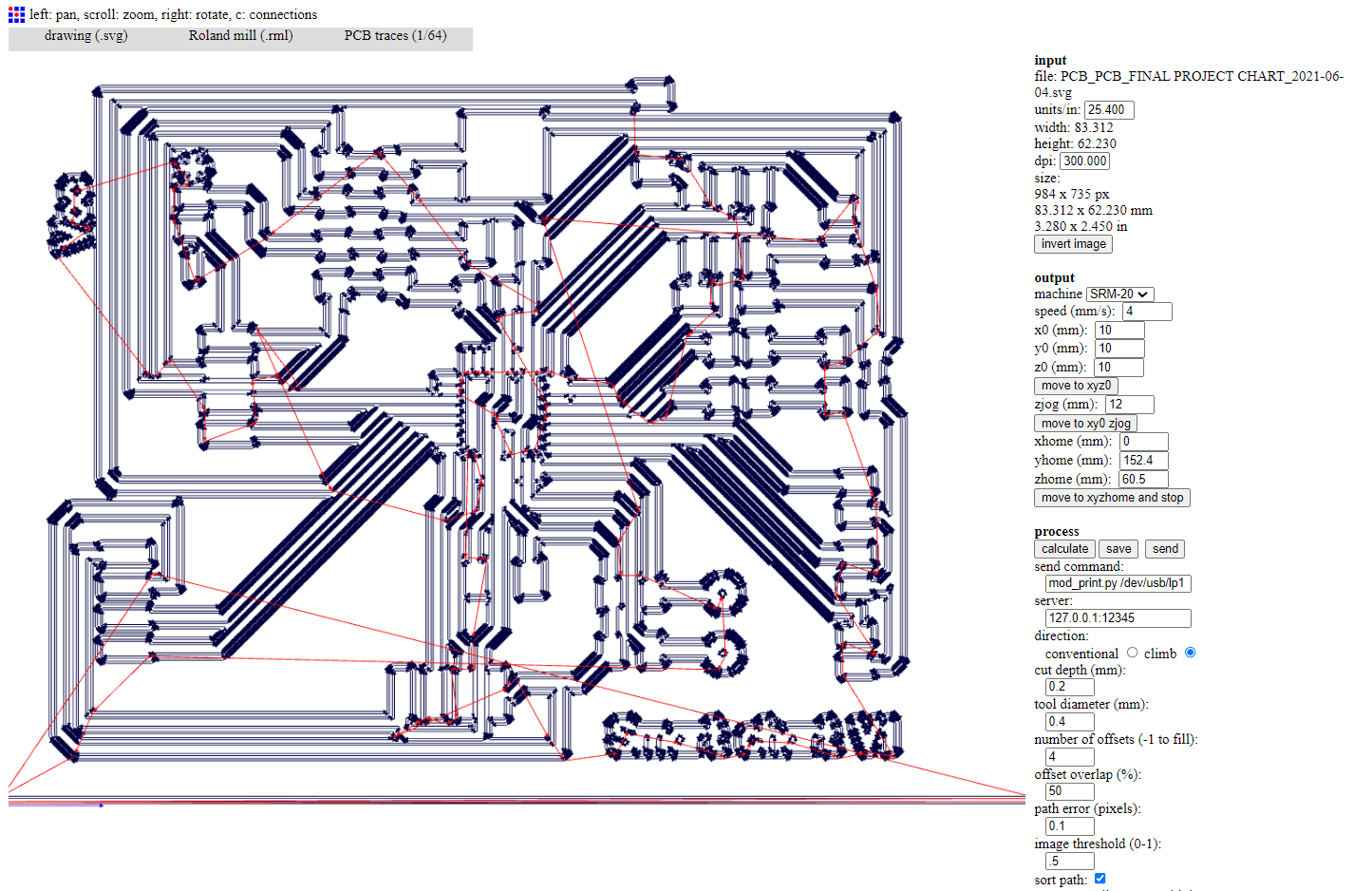
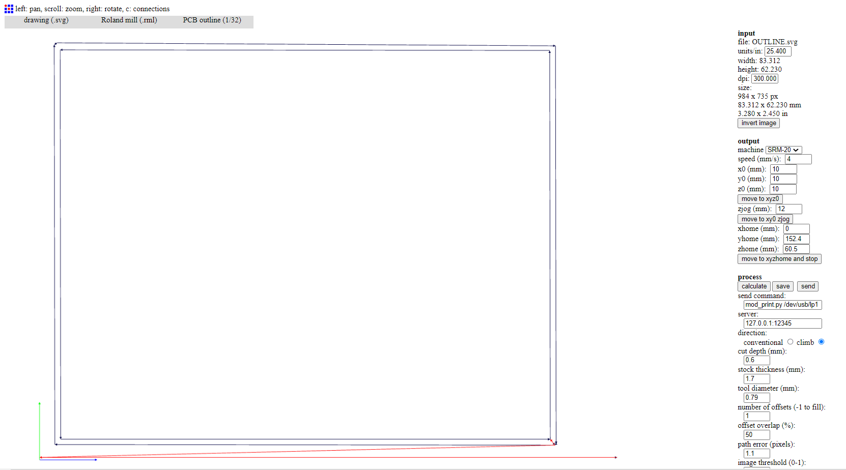
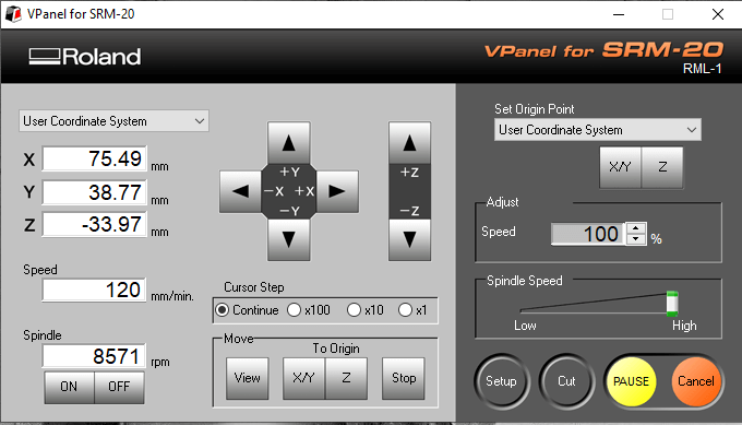
I downloaded 2 files, one for the TRACES.svg and one for the OUTLINE.svg, I must enter both files in fabmodules to generate the toolpaths to be able to mill my board, some important parameters:
- cut depth (mm): 0.2
- tool diameter (mm): 0.4
- number of offsets (-1 to fill): 4
- offset overlap (%): 50
- path error (pixels): 0.1
- image threshold (0-1): .5
- sort path: enabled
- sort merge diameter multiple: 1.5
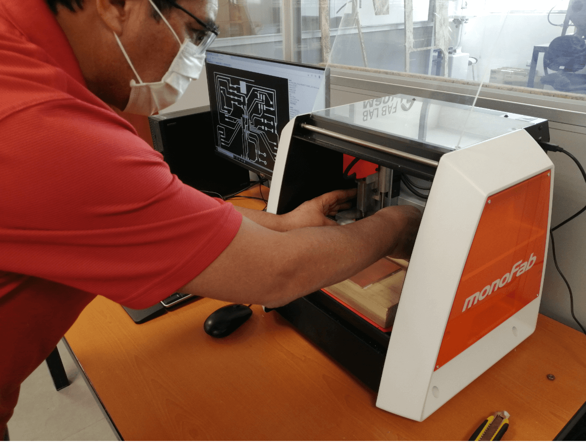
Milling, soldering and testing
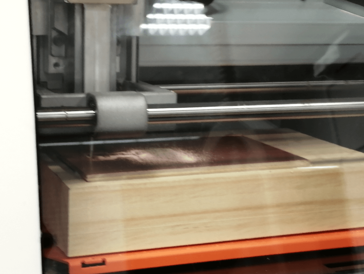
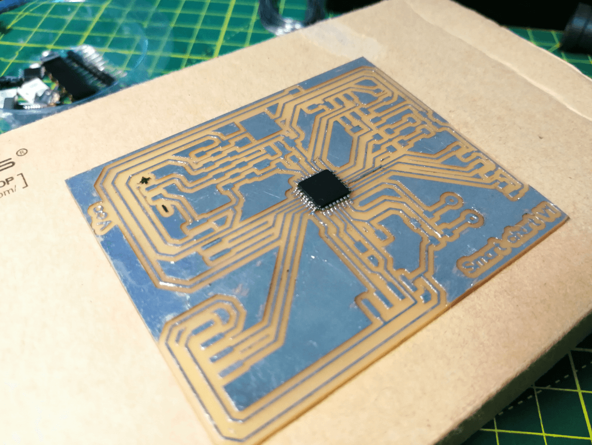
The milling process tested the resolution of our monofab because by using the Atmega328p-au microcontroller some traces were very close, first milling was performed with a 0.001 milling endmill (for super fine finishes), but the result was not the same, expected and added to the fact that our sacrificial bed was not leveled correctly, so it was discarded. Having correctly leveled our sacrificial bed, I decided to modify some tracks to be able to mill with a 1/64 endmill and luckily everything turned out perfect except for the + and - symbols.
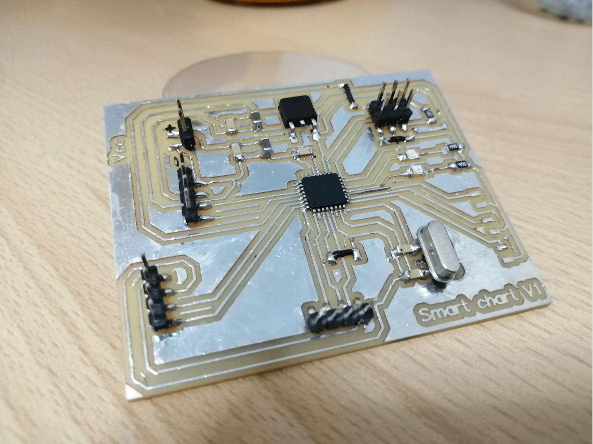
The welding process performed in a specific order, starting with the most important part that is the microcontroller and later diodes and capacitors, finally the highest components were soldered and 2 holes were also drilled to use the 16Mhz crystal oscillator. Some last tests were performed with the multimeter to check for a short circuit, fortunately everything worked correctly, so I connected my sensors and actuators to perform a quick test and check the correct operation of my PCB.


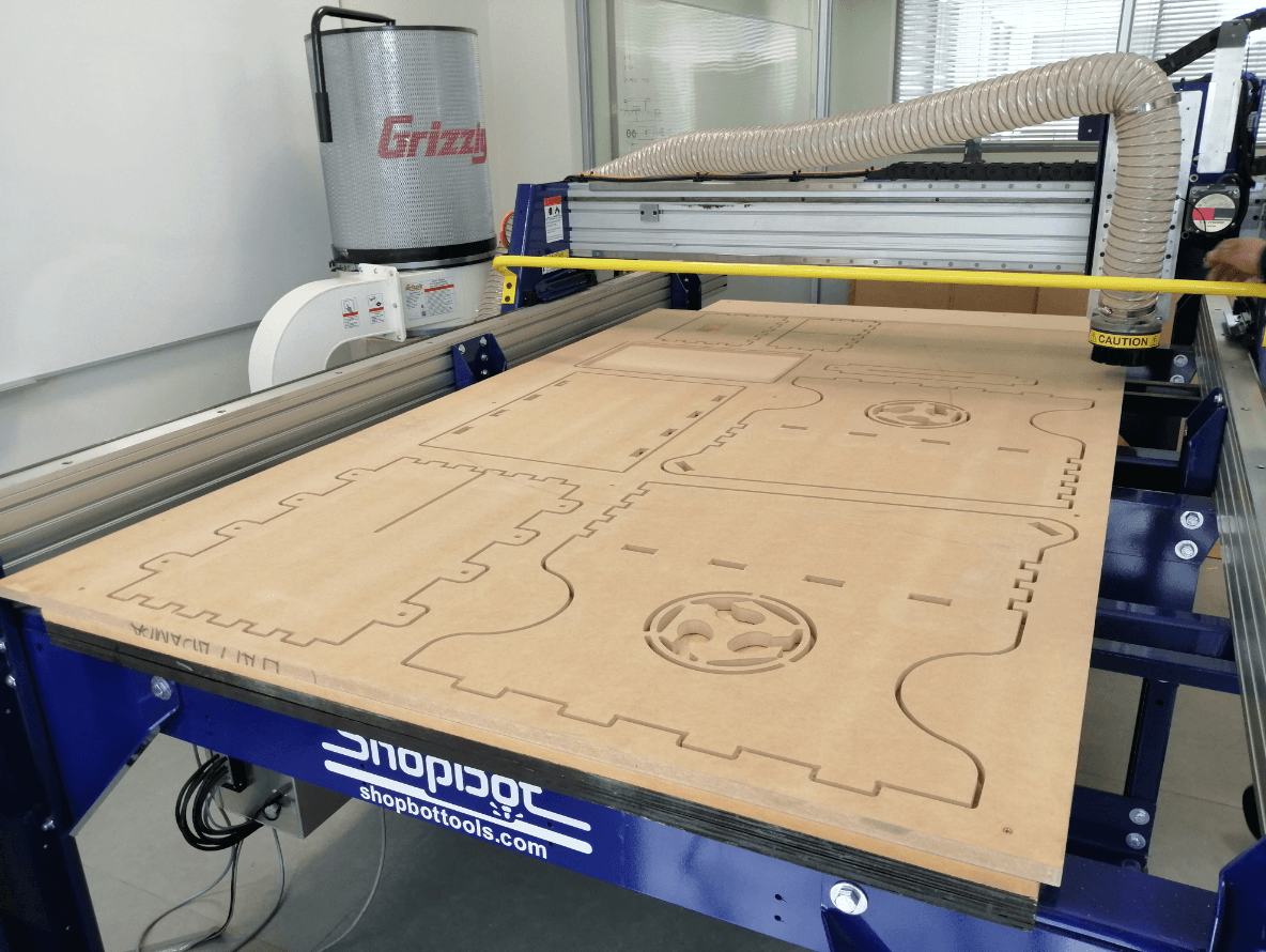
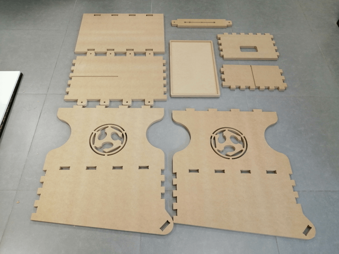
Design and cut of all the MDF parts
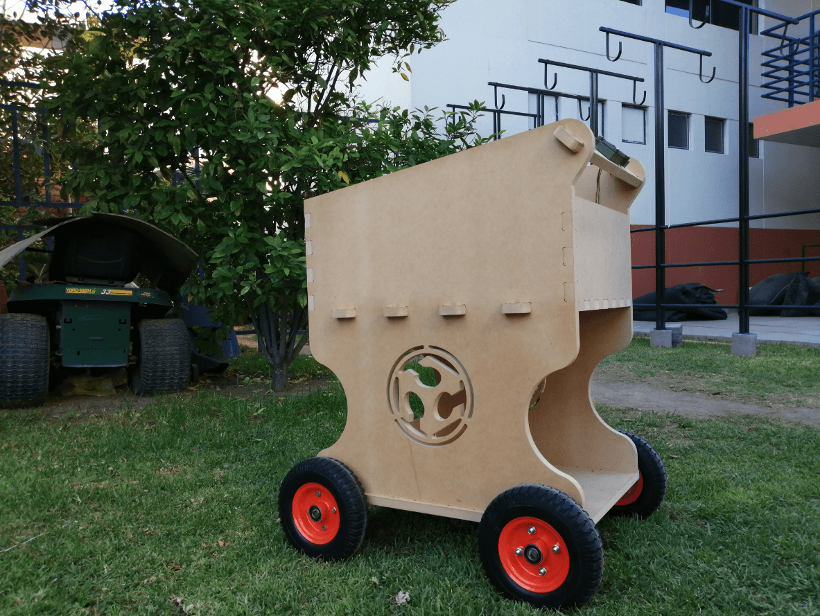
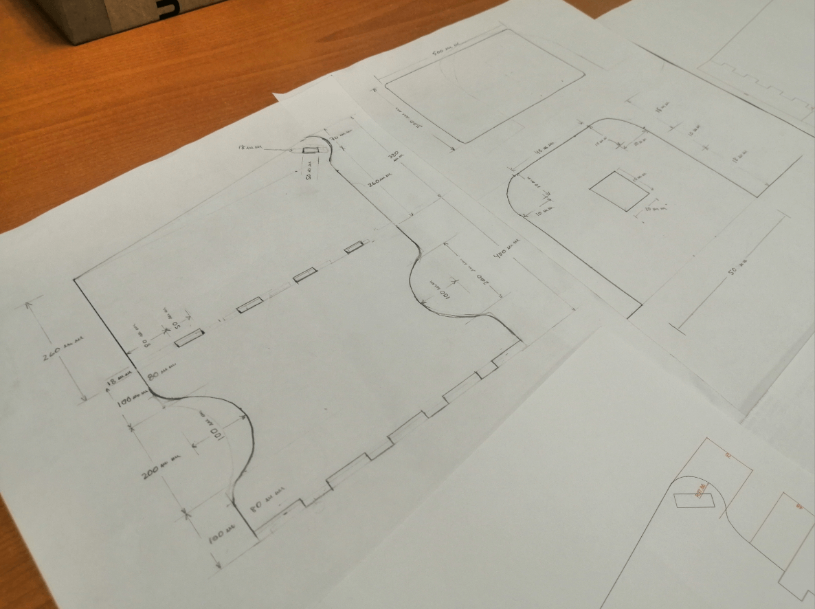
The parts of my cart went through a drastic modification, at first I thought of a design closer to the ground with a longer handle, later continuing with the philosophy of “make rather than buy” I leaned for a design more similar to a shopping cart, I decided to put my technical drawing skills to the test and draw some pieces as a reference for my idea, to later perfect them in Autocad.
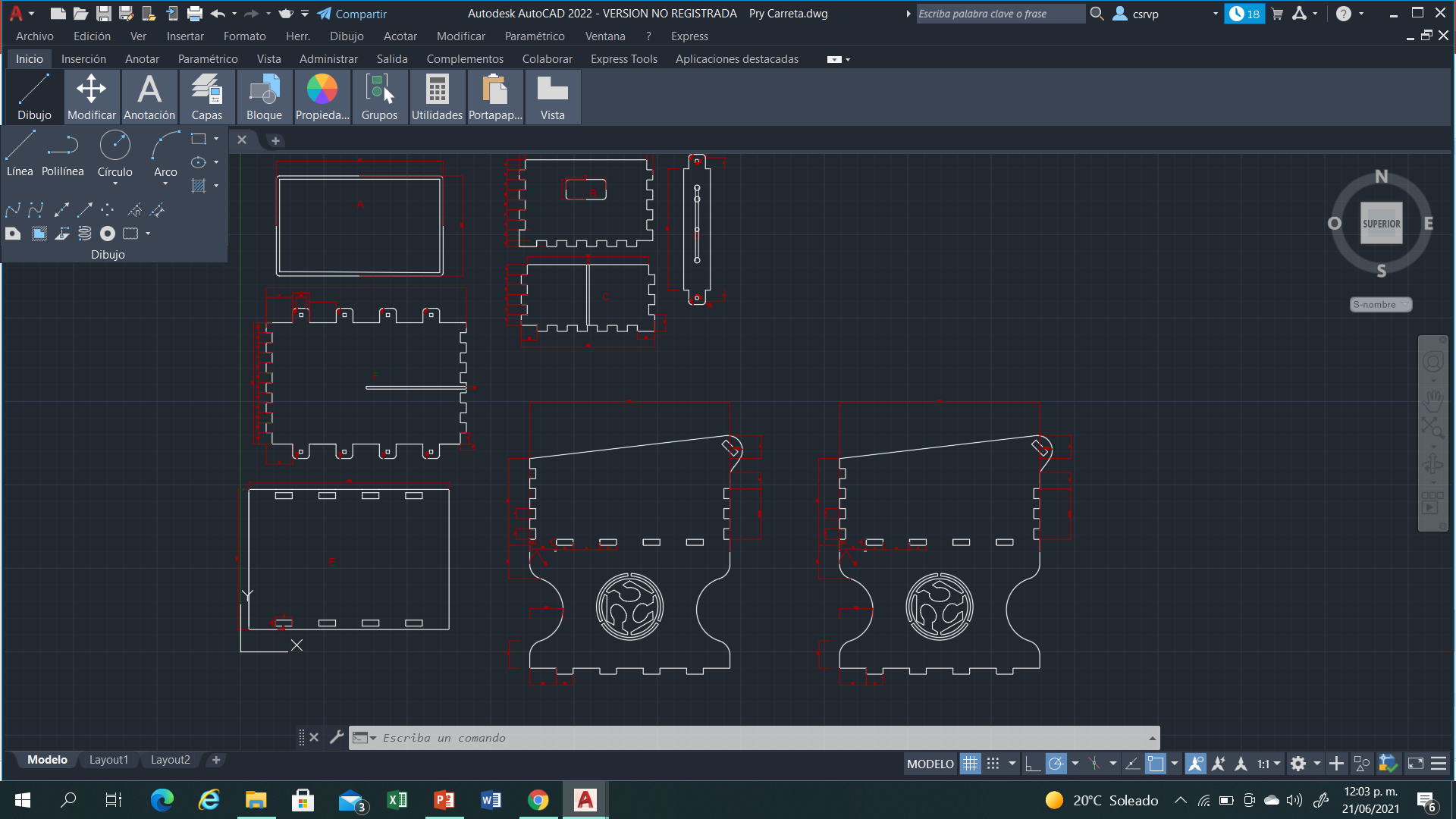
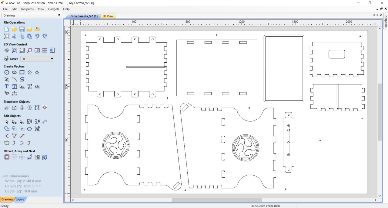
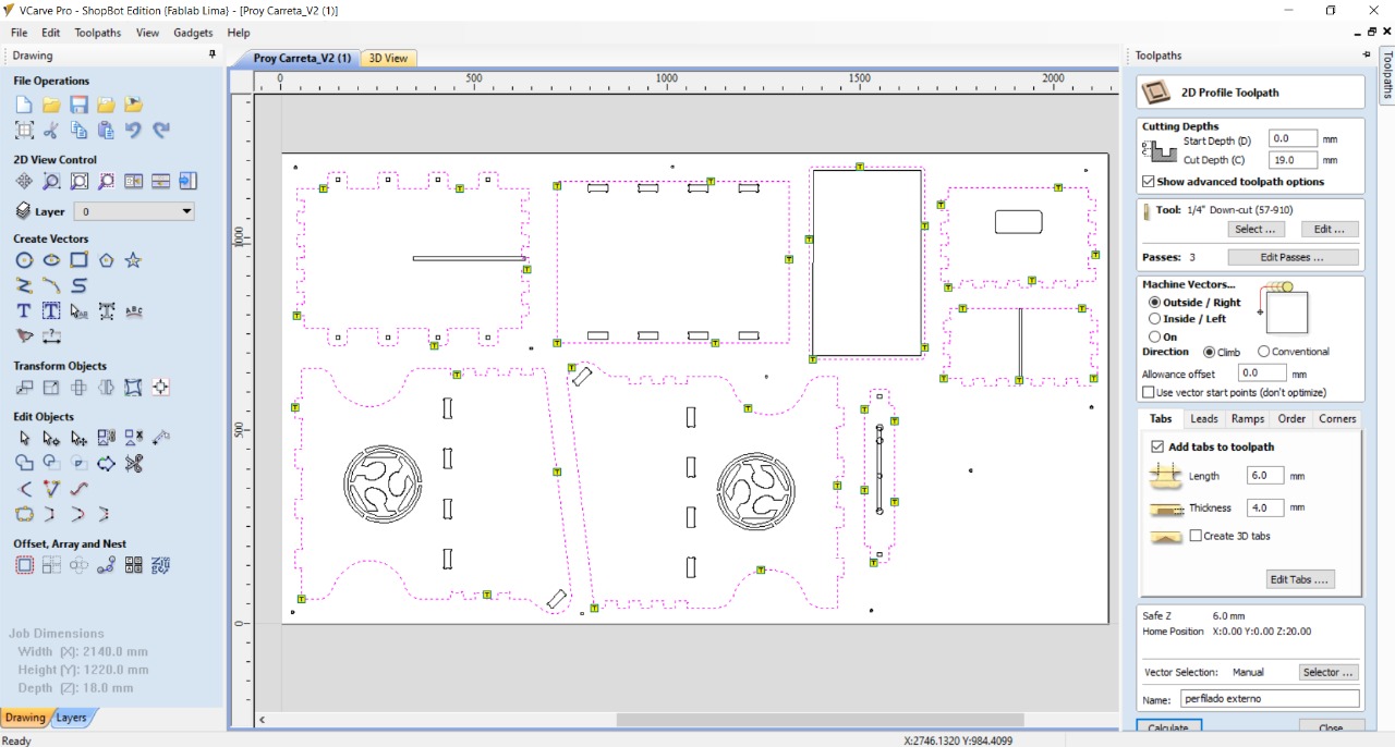
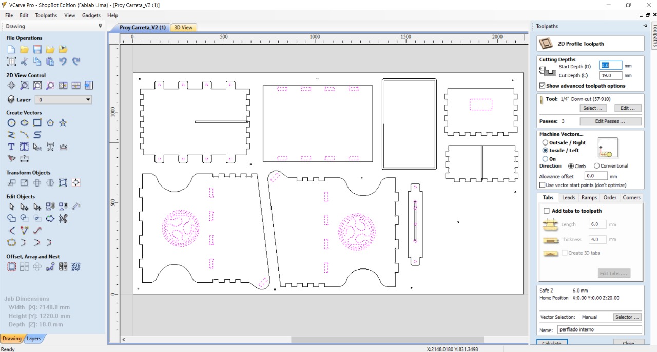
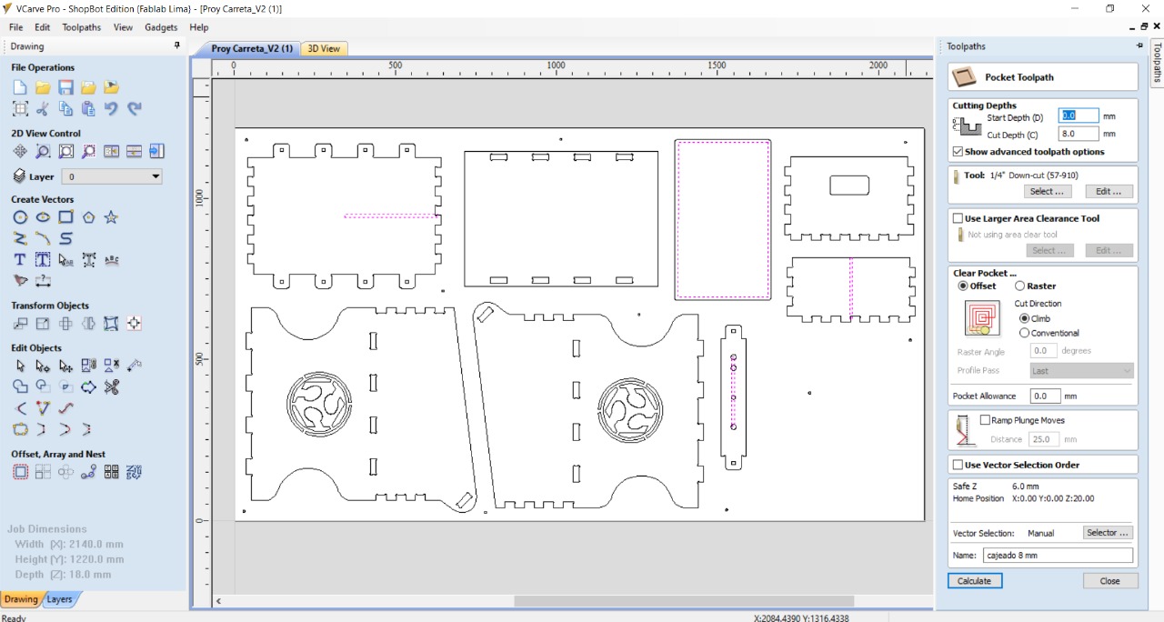
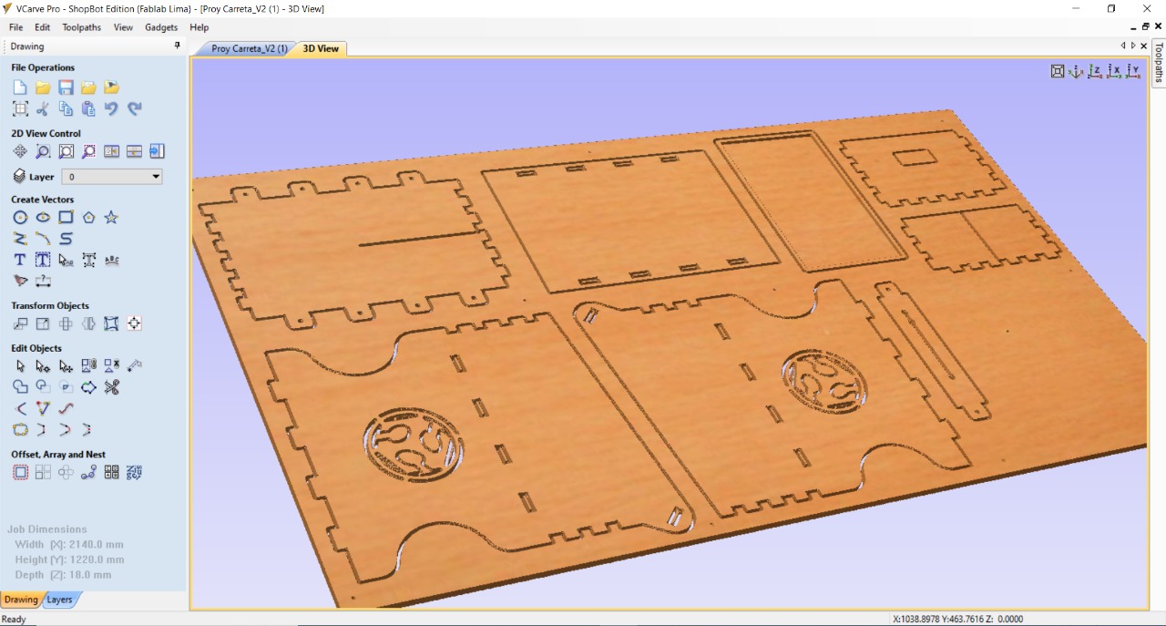
Subsequently, all the pieces were designed in Autocad using different types of joints as can be seen, then it was exported to Vcarve, using 3 main functions External cut for all parts, Internal cut for the fablab logo located on both sides of the cart and also to place the buttons and Pockets that were used to make the tray to hold the load cell and also to be able to transport the cables throughout the cart in an neat way.
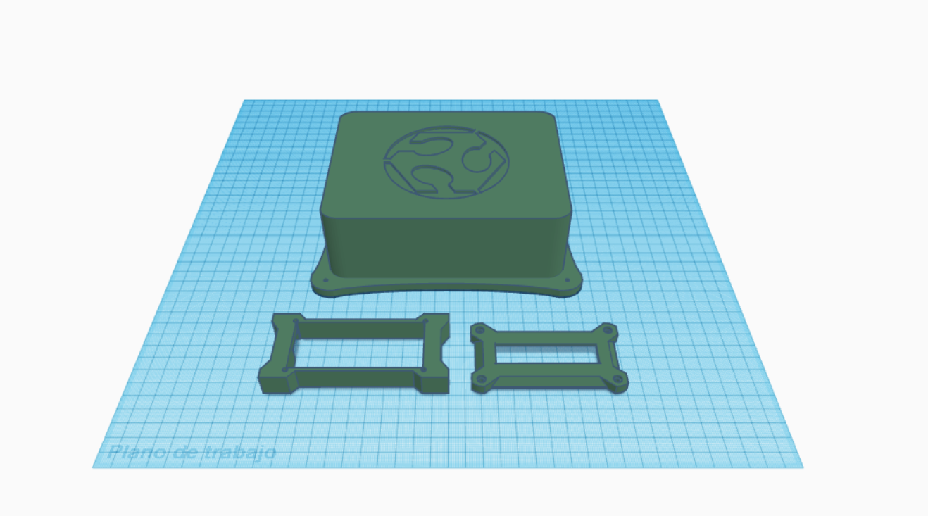
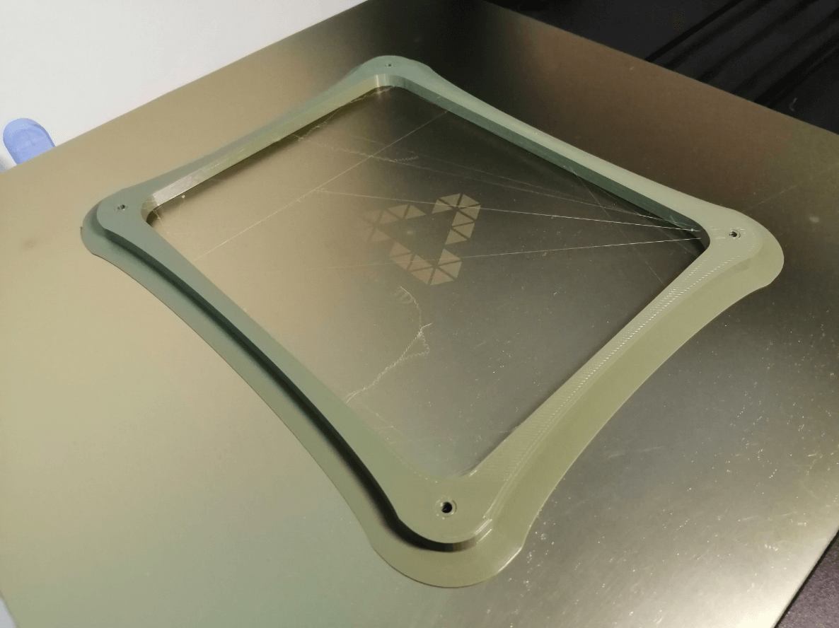
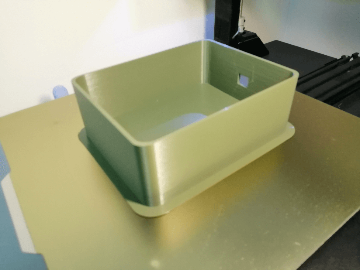
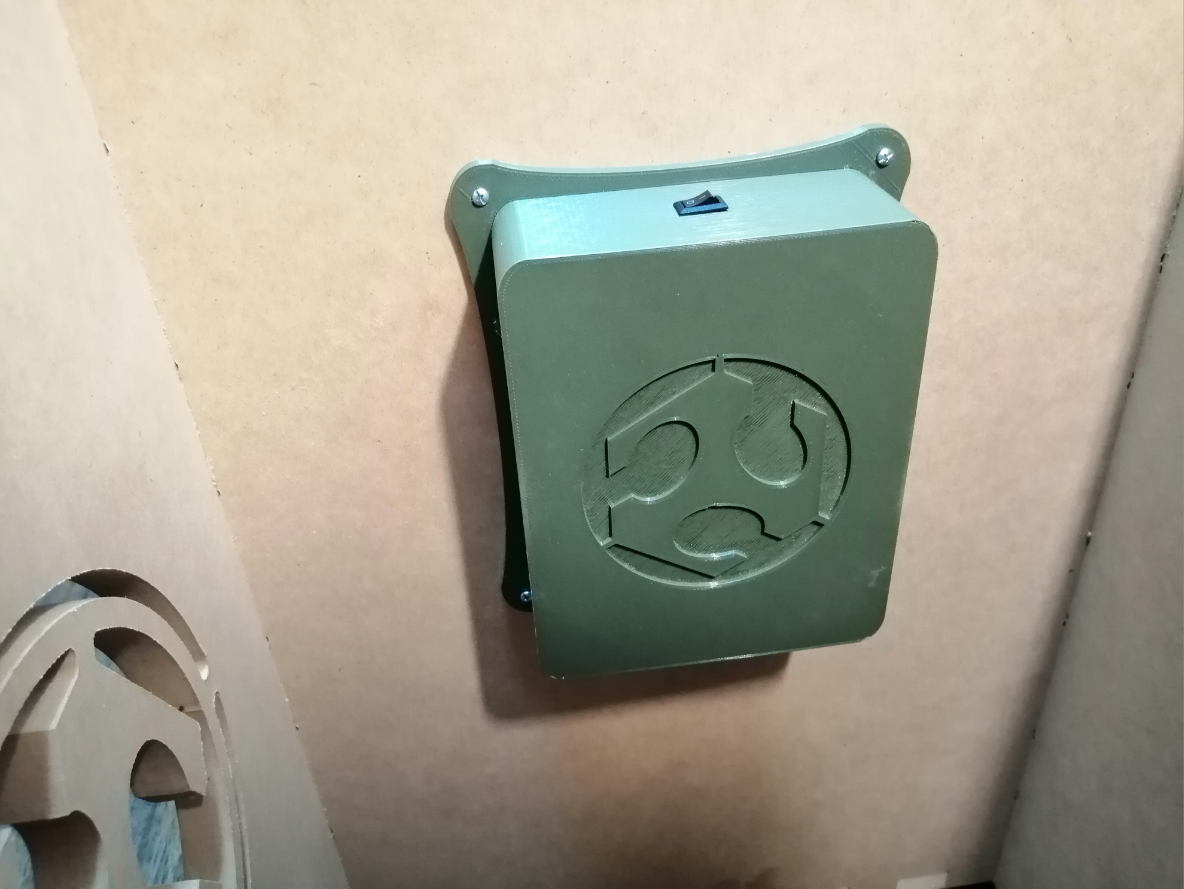
3D Design of the housings
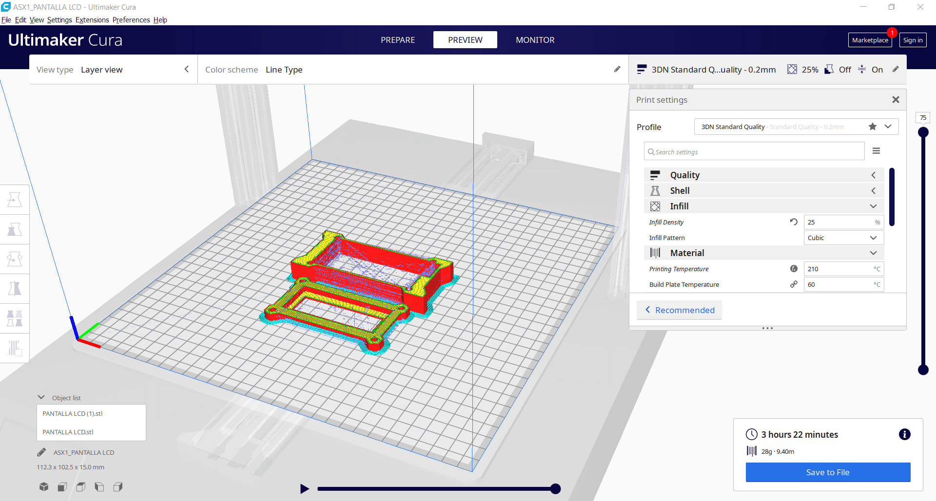
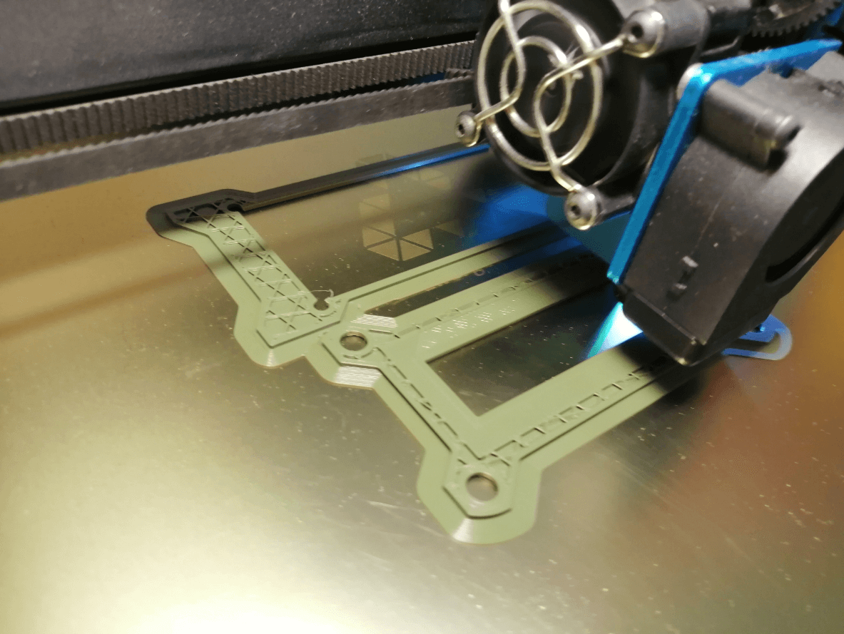
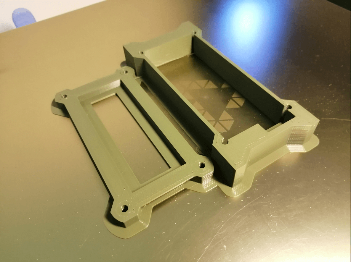
At first I planned to make a 3D printed handle together with a piece of silicone, but due to last minute changes, the shape of my cart underwent some important changes, it is still very important to protect the electronic part (screen and control card), so I decided to design a cover for each one, the designs are simple, nothing fancy, but I feel that they combine perfectly with my entire cart, to avoid the use of supports I divided the parts and later glued them, everything was designed in Tinkercad due to the small complexity that implied generating both pieces.
Wiring everything and adding connectors
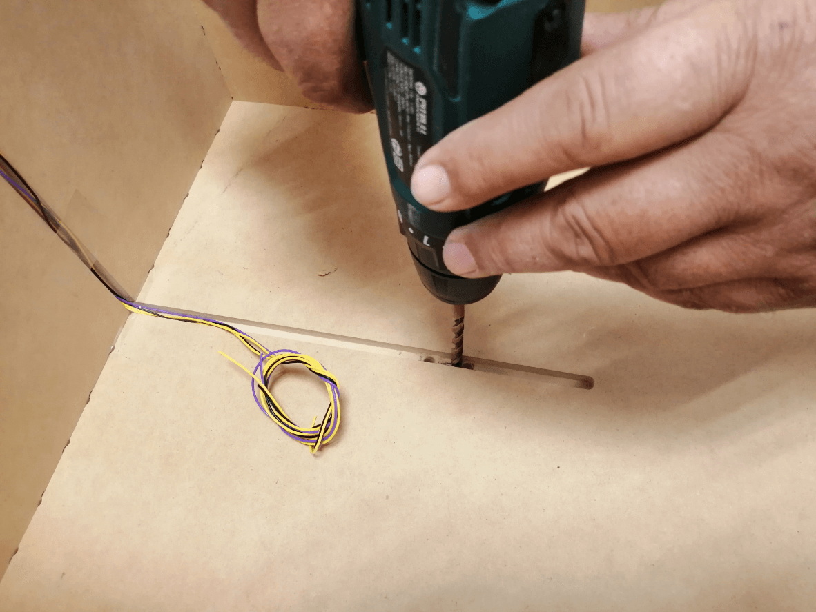
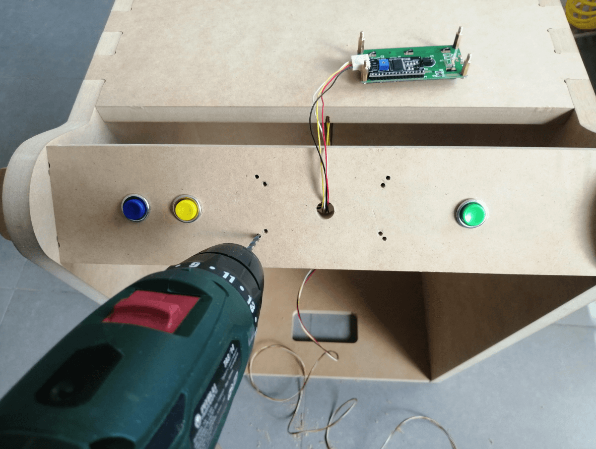
I decided to start by wiring the buttons to the cart by welding directly, as you can see in the images, I assigned pockets to be able to send the cables in the most organized way possible through the cart, without interrupting the operation of the cart, but forget to assign a hole In order to send the cables to the housing, this was solved quickly by using a drill and generating the hole for the wiring.
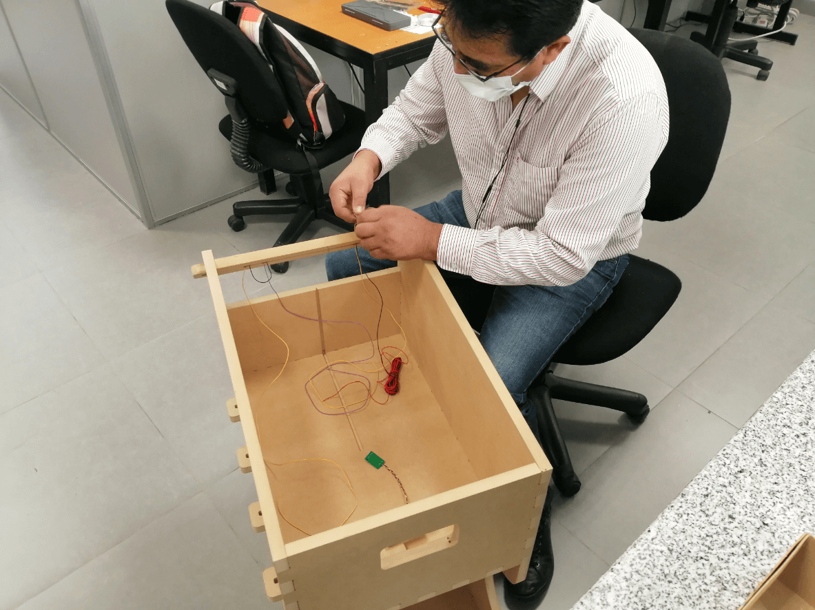
To guarantee the modularity of my project, I decided to use molex to connect all the sensors and actuators, that includes the LCD screen, since when wiring everything it would be very difficult to identify each of the cables, thanks to the molex I saved all that work and I was able to wire everything in a neat way.
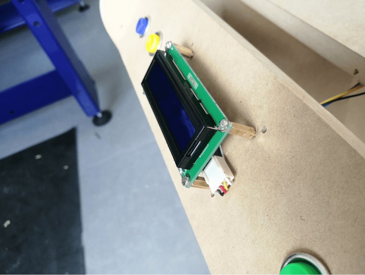
Due to the diameter of the endmill, I could not allocate the holes to place the screen on the handle, so I did this process using a drill with a 3mm diameter bit, in the same way with the holes for the 3D printed case, everything clicked correctly and I was able to continue with the other steps.
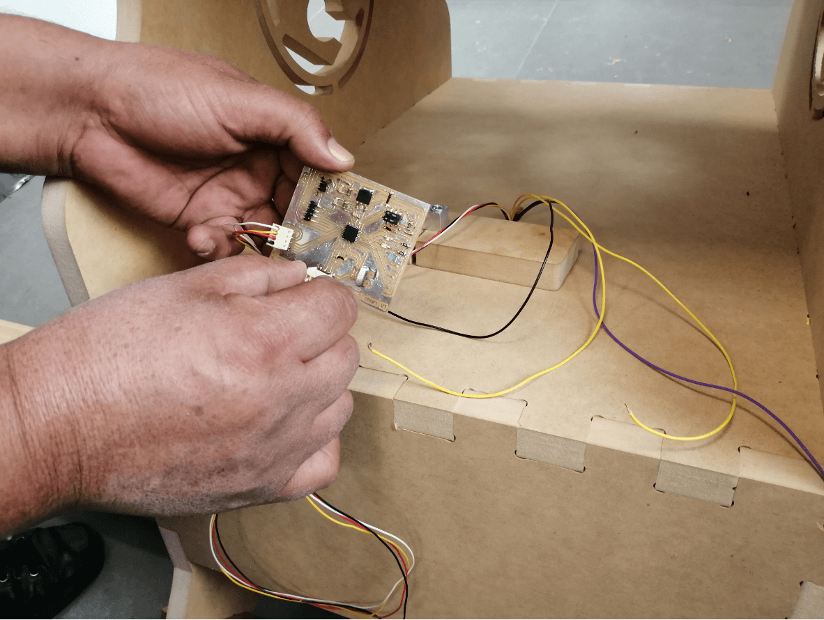
Almost finishing with the wiring process, it only remained to connect all the sensors and actuators to the PCB at the bottom of the cart, a process that was super simple thanks to all the connectors intended for each of the applications.
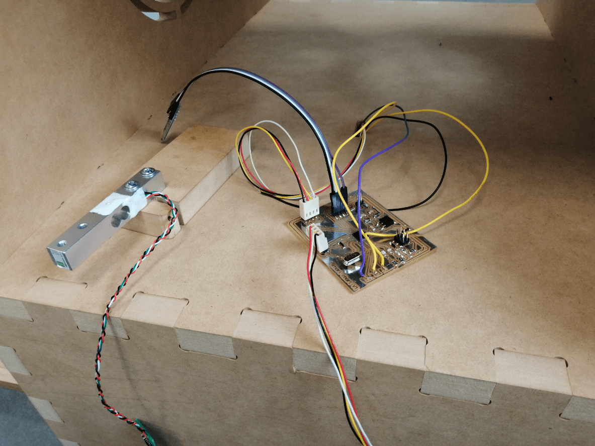
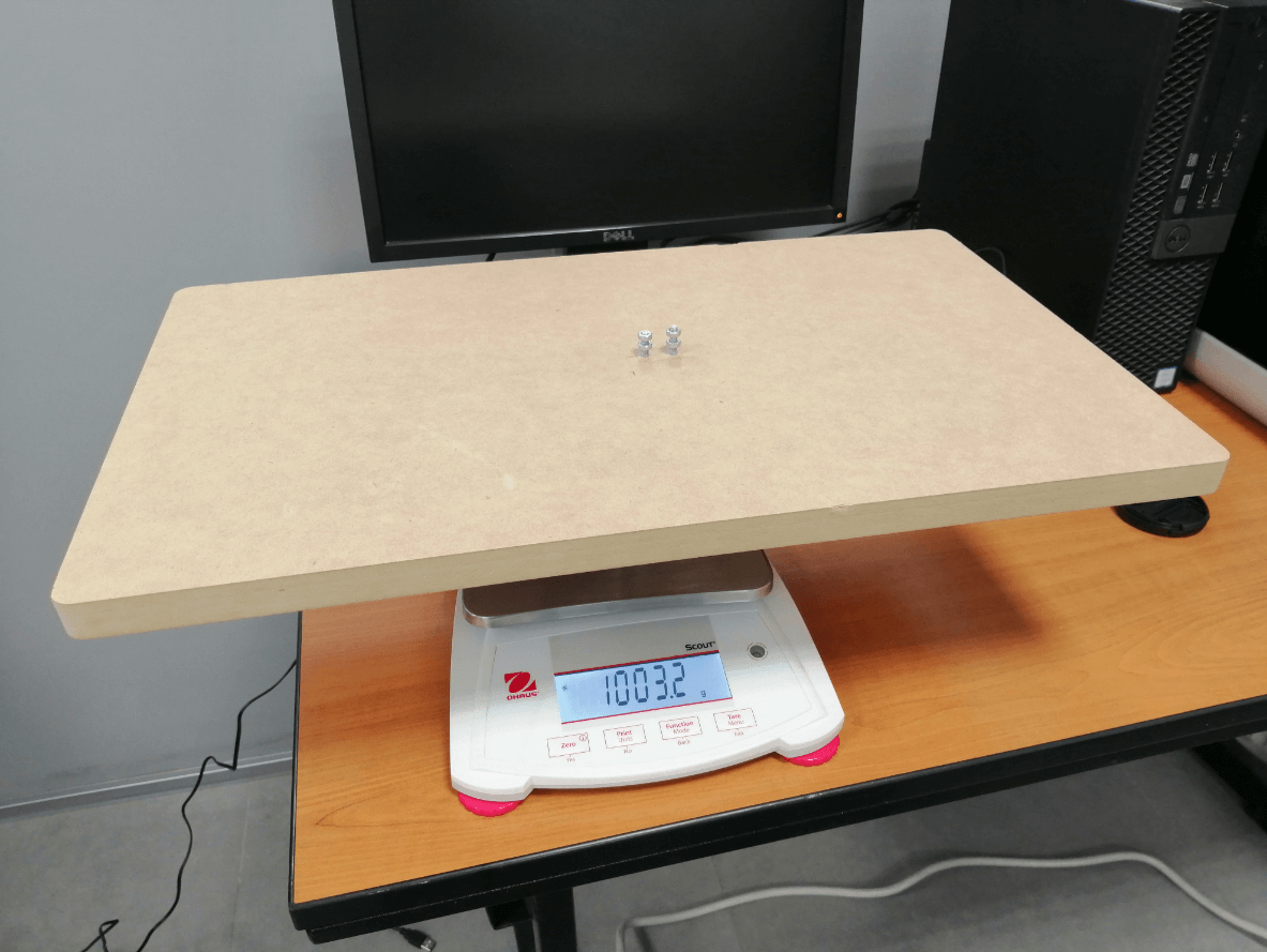
As a last step and to guarantee the correct functioning of the code, the total weight of the tray used to place the products on the scale was measured, later knowing that value will allow us to make some modifications to the code to guarantee the most accurate weighing.
Coding and testing
With everything placed and wired correctly in the cart I can dedicate myself entirely to programming, I will use the arduino IDE interface for the elaboration of my code because my board has the same capabilities as an arduino UNO, to start elaborating the code it is necessary to include libraries to interpret the scale information (Q2HX711.h), use the LCD screen (LiquidCrystal_I2C.h) and also to enable I2C communication (Wire.h).
The operation of the program has 2 parts, the first is a mandatory calibration at the time of starting the cart, this allows to guarantee a more precise measurement, the second part is in charge of interpreting the values obtained from the scale and the buttons and transforms them In information that will be shown on the LCD screen and will also be sent through the serial port (bluetooth) to be able to receive that information on the cell phone.
#include <Q2HX711.h>
#include <Wire.h>
#include <LiquidCrystal_I2C.h>
LiquidCrystal_I2C lcd(0x27, 20, 4); //sometimes the LCD adress is not 0x3f. Change to 0x27 if it dosn't work.
const byte hx711_data_pin = 3; //Data pin from HX711
const byte hx711_clock_pin = 2; //Clock pin from HX711
Q2HX711 hx711(hx711_data_pin, hx711_clock_pin); // prep hx711
int tara_button = 8; //Tara button
int count_button = 12; //Count button
int mode_button = 11; //Mode change button
float y1 = 1003.0; // MDF plate total weight
long x1 = 0L;
long x0 = 0L;
float avg_size = 10.0; // amount of averages for each mass measurement
float tara = 0;
bool tara_pushed = false;
bool count_pushed = false;
bool mode_pushed = false;
int mode = 0;
int count = 0;
float oz_conversion = 0.035274;
void setup() {
Serial.begin(9600); // prepare serial port
PCICR |= (1 << PCIE0); //enable PCMSK0 scan
PCMSK0 |= (1 << PCINT0); //Set pin D8 trigger an interrupt on state change.
PCMSK0 |= (1 << PCINT4); //Set pin D12 trigger an interrupt on state change.
PCMSK0 |= (1 << PCINT3); //Set pin D11 trigger an interrupt on state change.
pinMode(tara_button, INPUT_PULLUP);
pinMode(mode_button, INPUT_PULLUP);
pinMode(count_button, INPUT_PULLUP);
lcd.init(); //Init the LCD
lcd.backlight(); //Activate backlight
delay(1000); // allow load cell and hx711 to settle
// tare procedure
for (int ii = 0; ii < int(avg_size); ii++) {
delay(10);
x0 += hx711.read();
}
x0 /= long(avg_size);
lcd.clear();
lcd.setCursor(0, 0);
lcd.print(" Calibrating ");
lcd.setCursor(0, 1);
lcd.print(" .... ");
int ii = 1;
while (true) {
if (hx711.read() < x0 + 10000)
{
//do nothing...
}
else
{
ii++;
delay(2000);
for (int jj = 0; jj < int(avg_size); jj++) {
x1 += hx711.read();
}
x1 /= long(avg_size);
break;
}
}
lcd.clear();
lcd.setCursor(0, 0);
lcd.print(" All set!!! ");
}
void loop() {
long reading = 0;
for (int jj = 0; jj < int(avg_size); jj++)
{
reading += hx711.read();
}
reading /= long(avg_size);
float ratio_1 = (float) (reading - x0);
float ratio_2 = (float) (x1 - x0);
float ratio = ratio_1 / ratio_2;
float mass = y1 * ratio;
Serial.print(mass - tara);
Serial.print("|");
Serial.print(count);
//Serial.print("|");
delay(300);
if (tara_pushed)
{
tara = mass;
tara_pushed = false;
lcd.setCursor(0, 0);
lcd.print(" TARA ");
lcd.setCursor(0, 1);
lcd.print(" . ");
delay(300);
//Serial.print(".");
lcd.setCursor(0, 1);
lcd.print(" .. ");
delay(300);
//Serial.println(".");
lcd.setCursor(0, 1);
lcd.print(" ... ");
delay(300);
}
if (count_pushed)
{
mode = 2;
count_pushed = false;
delay(300);
}
if (mode_pushed)
{
mode = 1;
mode_pushed = false;
delay(300);
}
if (mode == 0)
{
lcd.clear();
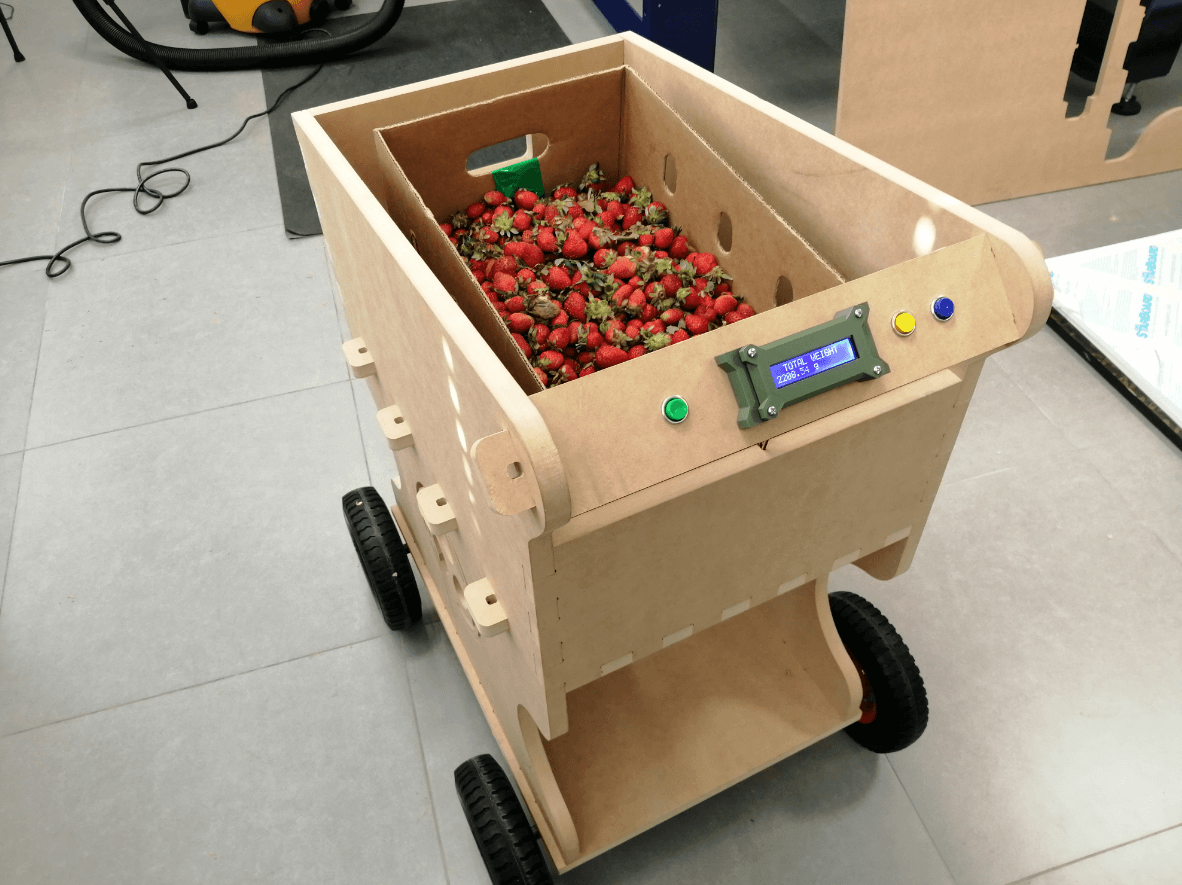
lcd.setCursor(0, 0);
lcd.print(" TOTAL WEIGHT ");
lcd.setCursor(0, 1);
lcd.print(mass - tara);
lcd.print(" g");
}
else if (mode == 1)
{
lcd.clear();
lcd.setCursor(0, 0);
lcd.print(" TALLY COUNTER ");
lcd.setCursor(0, 1);
lcd.print(count);
lcd.print(" crops");
delay(1000);
mode = 0;
}
else if (mode == 2)
{
count = count + 1;
lcd.clear();
lcd.setCursor(0, 0);
lcd.print(" TALLY COUNTER ");
lcd.setCursor(0, 1);
lcd.print(count);
lcd.print(" crops");
mode = 0;
}
}
//interruption to detect buttons
ISR(PCINT0_vect)
{
if (!(PINB & B00000001))
{
tara_pushed = true; //Tara button was pushed
}
if (!(PINB & B00000100))
{
count_pushed = true; //Count button was pushed
}
if (!(PINB & B00001000))
{
mode_pushed = true; //Mode button was pushed
}

Monitoring app
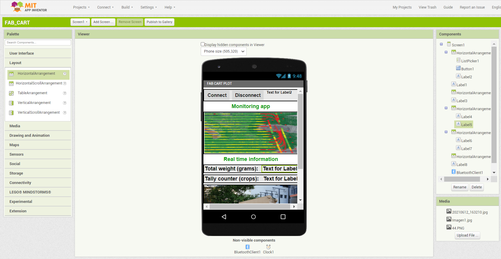
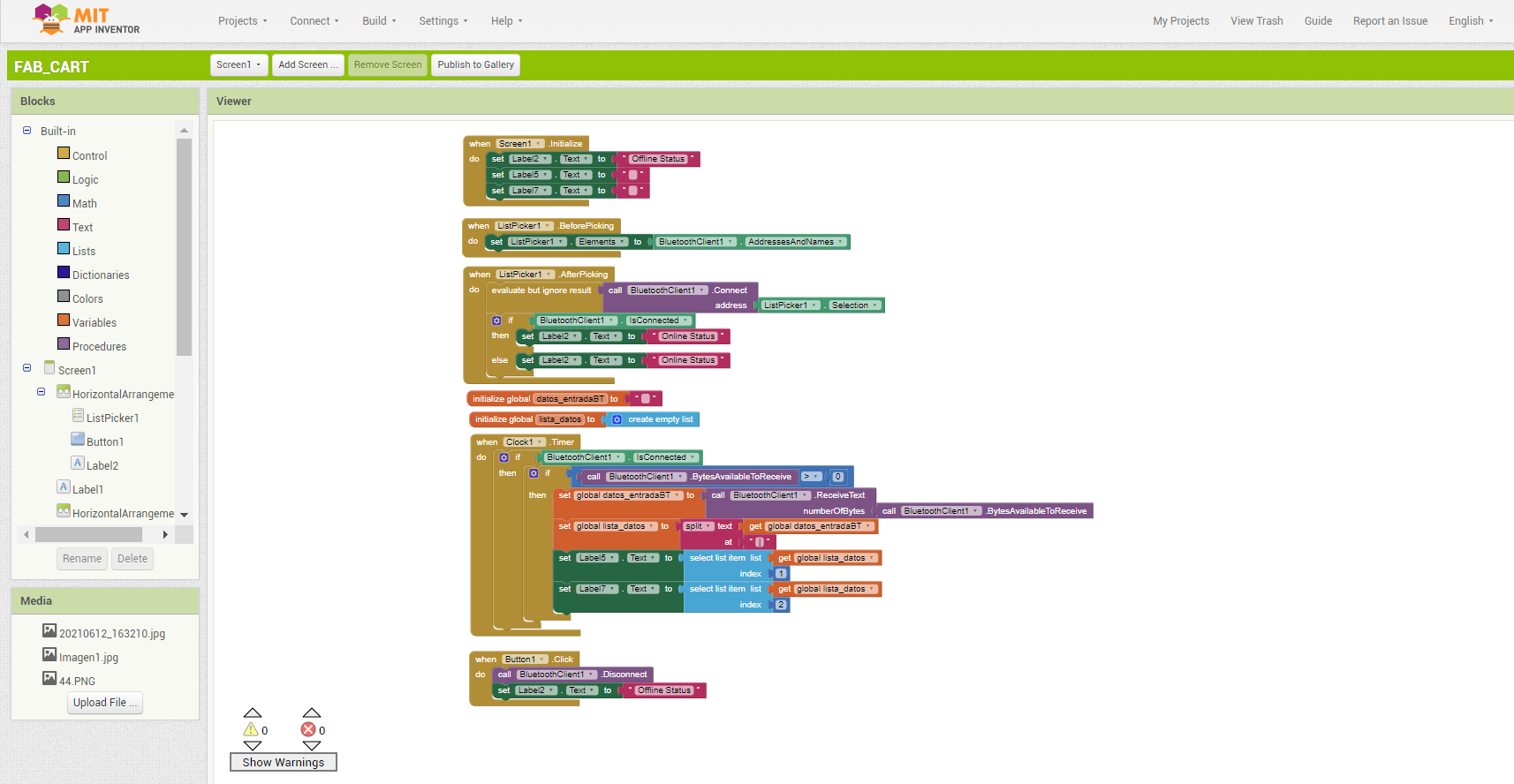
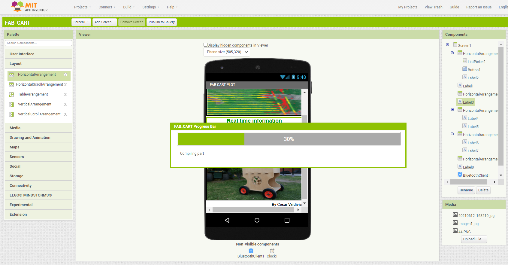
The function of the app is to monitor, at this very early stage and with my limited knowledge of app design, I elaborated a basic app that shows the values in real time, both of the weight and the tally counter, later I would like to load all that information to a server and show a heat map of the areas that have the best production, I decided to simulate that by adding an image in the GUI of a crop and the roads traveled.
Likewise, I focus all my effort on the correct operation of the application and that the refresh time is minimal to be able to appreciate subtle changes in weight quickly, I am sure that many improvements can be made but in the same way I am satisfied with the result.
The following video shows the real-time operation of my application, due to the intensity of sunlight, I had to film in an environment with low light to be able to appreciate the LCD screen and also the application on my cell phone, I used 3 different fruits and once I finished harvesting one, the value of the tally counter would rise by one.

Final result